room air conditioner -...
TRANSCRIPT

LG RoomAir ConditionerSERVICE MANUAL
LG
MODEL: LWHD7000HR, LWHD1200HR
CAUTION
website http://www.lgservice.com
• BEFORE SERVICING THE UNIT, READ THE SAFETY PRECAUTIONS IN THIS MANUAL.
• ONLY FOR AUTHORIZED SERVICE PERSONNEL.
2 Room Air Conditioner
Air Conditioner Service Manual
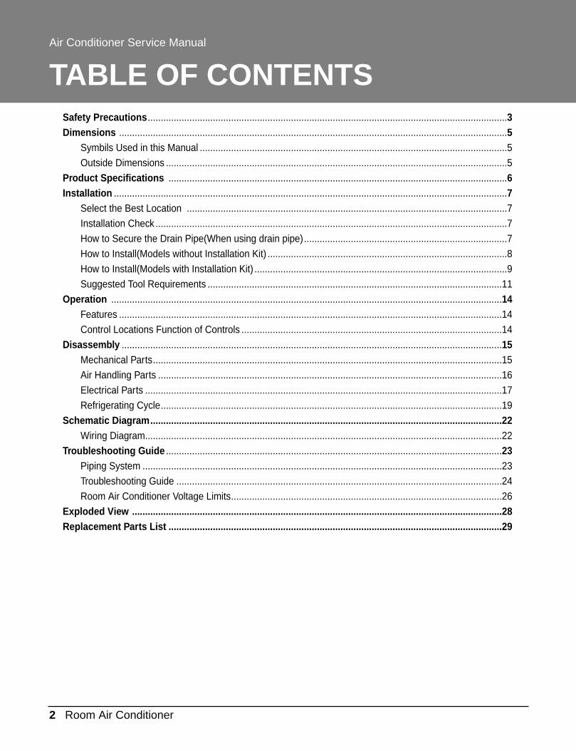
TABLE OF CONTENTSSafety Precautions..........................................................................................................................................3Dimensions .....................................................................................................................................................5
Symbils Used in this Manual ......................................................................................................................5
Outside Dimensions ...................................................................................................................................5
Product Specifications ..................................................................................................................................6Installation .......................................................................................................................................................7
Select the Best Location ...........................................................................................................................7
Installation Check .......................................................................................................................................7
How to Secure the Drain Pipe(When using drain pipe)..............................................................................7
How to Install(Models without Installation Kit) ............................................................................................8
How to Install(Models with Installation Kit) .................................................................................................9
Suggested Tool Requirements .................................................................................................................11
Operation ......................................................................................................................................................14Features ...................................................................................................................................................14
Control Locations Function of Controls ....................................................................................................14
Disassembly ..................................................................................................................................................15Mechanical Parts......................................................................................................................................15
Air Handling Parts ....................................................................................................................................16
Electrical Parts .........................................................................................................................................17
Refrigerating Cycle...................................................................................................................................19
Schematic Diagram.......................................................................................................................................22Wiring Diagram.........................................................................................................................................22
Troubleshooting Guide .................................................................................................................................23Piping System ..........................................................................................................................................23
Troubleshooting Guide .............................................................................................................................24
Room Air Conditioner Voltage Limits........................................................................................................26
Exploded View ..............................................................................................................................................28Replacement Parts List ................................................................................................................................29

Service Manual 3
Safety Precautions
Safety Precautions
To prevent injury to the user or other people and property damage, the following instructions mustbe followed.■ Incorrect operation due to ignoring instruction will cause harm or damage. The seriousness is
classified by the following indications.
■ Meanings of symbols used in this manual are as shown below.
WARNING
CAUTION
This symbol indicates the possibility of death or serious injury.
This symbol indicates the possibility of injury or damage to property only.
WARNING■ Installation
Do not use damaged power cord plugs, or aloose socket.
• There is risk of fire or electric shock.
Always use the power plug and socket withthe ground terminal.
• There is risk of electric shock.
Be sure not to do.
Be sure to follow the instruction.
4 Room Air Conditioner
Safety Precautions
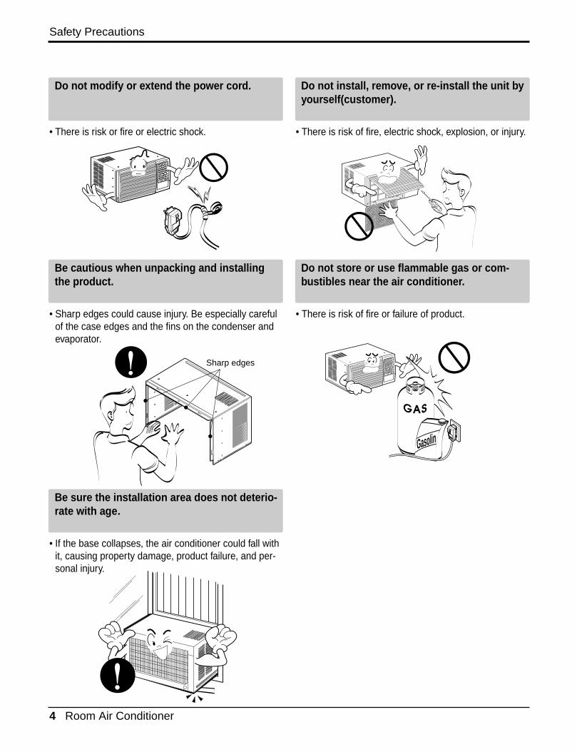
Do not modify or extend the power cord.
• There is risk or fire or electric shock.
Do not install, remove, or re-install the unit byyourself(customer).
• There is risk of fire, electric shock, explosion, or injury.
Be cautious when unpacking and installingthe product.
• Sharp edges could cause injury. Be especially carefulof the case edges and the fins on the condenser andevaporator.
Do not store or use flammable gas or com-bustibles near the air conditioner.
• There is risk of fire or failure of product.
Be sure the installation area does not deterio-rate with age.
• If the base collapses, the air conditioner could fall withit, causing property damage, product failure, and per-sonal injury.
Gasolin
Sharp edges
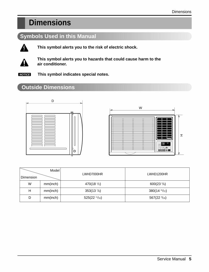
Dimensions
DimensionsH
W
D
TIMER ENERGYSAVER MODE
On/OffOn/Off Fan Cool
Heat
W mm(inch) 470(18 1/2) 600(23 5/8)
H mm(inch) 353(13 7/8) 380(14 31/22)
D mm(inch) 525(22 11/16) 567(22 5/16)
Model
DimensionLWHD7000HR LWHD1200HR
Outside Dimensions
This symbol alerts you to the risk of electric shock.
This symbol alerts you to hazards that could cause harm to theair conditioner.
This symbol indicates special notes.NOTICE
Symbols Used in this Manual
Service Manual 5

6 Room Air Conditioner
Specfications
Product Specifications
POWER SUPPLY
COOLING CAPACITY (Btu/h)
INPUT (W)
RUNNING CURRENT (A)
E.E.R (BTU/W.h)
HEATING CAPACITY (Btu/h)
INPUT (W)
RUNNING CURRENT (A)
INDOOR(°C)
OUTDOOR(°C)
INDOOR(°C)
OUTDOOR(°C)
REFRIGERANT (R-22) CHARGE
EVAPORATOR
CONDENSER
FAN, INDOOR
FAN, OUTDOOR
FAN SPEEDS, FAN/COOLING/HEATING
FAN MOTOR
OPERATION CONTROL
ROOM TEMP. CONTROL
AIR DIRECTION CONTROL
CONSTRUCTION
ELECTRIC HEATER
COMPRESSOR
PROTECTOR FAN MOTOR
ELECTRIC HEATER
POWER CORD
DRAIN SYSTEM
NET WEIGHT (lbs/kg)
OUTSIDE DIMENSION (inch)
(W x H x D) (mm)
1Ø,115V, 60Hz 1Ø, 208/230V, 60Hz
7,000 11,500/12,000
720 1,170/1,220
6.6 5.5/5.8
9.7 9.8
3850 9,200/11,200
1260 2,900/3,500
11.0 14.0/15.3
26.7 (DB)* 19.4 (WB)**
35 (DB)* 23.9 (WB)**
21.1 (DB)* 15.6 (DB)**
8.3 (DB)* 6.1 (DB)**
330(11.6 oz) 545(19.2 oz)
2ROW 16STACKS 2ROW 13STACKS
2ROW 16STACKS 2ROW 17STACKS
BLOWER
PROPELLER TYPE FAN WITH SLINGER-RING
1 / 2 / 2 1 / 2 / 2
4 POLES 6 POLES
TOUCH PANEL
THERMISTOR
VERTICAL LOUVER(RIGHT&LEFT)
HORIZONTAL LOUVER(UP&DOWN)
SLIDE IN-OUT CHASSIS
1.2KW, 115 3.5KW, 230V
OVERLOAD PROTECTOR
INTERNAL THERMAL PROTECTOR
FUSE LINK, BIMETAL THERMOSTAT
6m(3 WIRE WITH GROUNDING)
ATTACHMENT PLUG(CORD-CONNECTED TYPE)
DRAIN PIPE OR SPLASHED BY FAN SLINGER
64/29 97/44
18 X 13 7/8 X 20 11/16 23 5/8 X 14 31/22 X 22 5/16
470 X 353 X 525 600 X 380 X 567
LWHD7000HR LWHD1200HRMODELS
ITEMS
OPERATINGCONDITION
COOLING
HEATING
* DB:Dry Bulb**WB:Wet BulbNOTE: Please refer to Label Quality on the produst since this specification may be changed for improving performance.

Service Manual 7
Installation
Installation
Select the Best Location
Installation Check
How to Secure the Drain Pipe(When using drain pipe)
1.To prevent vibration and noise, make sure the unit isinstalled securely and firmly.
2.Install the unit where the sunlight does not shine directlyon the unit.
3.The outside of the cabinet must extend outward for atleast 12" and there should be no obstacles, such as afence or wall, within 20" from the back of the cabinetbecause it will prevent heat radiation of the condenser.Restriction of outside air will greatly reduce the coolingefficiency of the air conditioner.
CAUTION: All side louvers of the cabinetmust remain exposed to the outside ofthe structure.
4.Install the unit a little slanted so the back is slightly lowerthan the front (about 1/2"). This will help force condensedwater to the outside.
5.Install the unit from the bottom about 30"~60" above thefloor level.
The setting conditions must be checked prior to initial starting.The following items are especially important checking points when the installation is finished.1. Grounding wire (Green or Green and Yellow) is provided in the power cord. The green wire must be grounded.2. Connect to a single-outlet 15A circuit.
(or 20A circuit for Electric Heater Model)3. To avoid vibration or noise, make sure the air conditioner is installed securely.4 Avoid placing furniture or draperies in front of the air inlet and outlet.
In humid weather, excess water may cause the BASE PAN to overflow. To drainthe water, remove the DRAIN CAP and secure the DRAIN PIPE to the rear hole ofthe BASE PAN. Press the drain pipe into the hole by pushing down and away fromthe fins to avoid injury.
Optional1. Install the drain pan over the corner of the cabinet where you removed the
plug with 4 (or 2) screws.2. Connect the drain hose to the outlet located at the bottom of the drain pan.
You can purchase the drain hose or tubing locally to satisfy your particularneeds. (Drain hose is not supplied).
3. Select the most appropriate connection from among the following figures (byconsidering the hole of the unit) to fit drain pan to your own unit.
AWNING
COOLED AIRHEAT
RADIATION
30"~
60"
ABOUT 1/2"Over 20"
FENCE
Drain pipe
Drain cap
Fig. 4Fig. 3
Fig. 2DRAINPAN DRAIN HOSE
Fig. 1
CABINET SCREW
Figure 1

8 Room Air Conditioner
Installation
How to Install(Models without Installation Kit)1. Remove the screws that fasten the cabinet
at both sides and at the back.
2. Slide the unit from the cabinet by grippingthe base pan handle and pulling forwardwhile bracing the cabinet.
3. Remove EPS Material.
4. Slide the unit into the cabinet.
CAUTION: For security pur-pose, reinstall screw at cabi-net's sides.
5. Attach the front grille to the cabinet by inserting the tabs on the grille into the tabson the fornt of the cabinet. Push the grille inuntil it snaps into place.
6. Lift the inlet grille and secure it with a screwthrough the front grille.
Shipping screws
TIMER ENERGYSAVER MODE
On/Off
On/Off
Fan Cool
Heat
TIMER ENERGYSAVER MODE
On/Off
On/Off
Fan Cool
Heat
EPS Material
TIMER ENERGYSAVER MODE
On/Off
On/Off
Fan Cool
Heat
Power cord
Screw
ScrewTIMER ENERGYSAVER MODE
On/Off
On/Off
Fan Cool
Heat
TIMERENERGY
SAVERMODE
On/Off
On/Off
Fan Cool
Heat
Service Manual 9
Installation
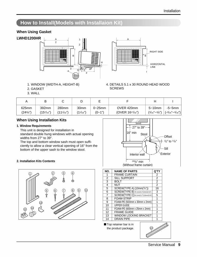
How to Install(Models with Installaion Kit)
When Using Gasket
When Using Installation Kits1. Window Requirements
This unit is designed for installation in standard double hung windows with actual openingwidths from 27" to 39".The top and bottom window sash must open suffi-ciently to allow a clear vertical opening of 16" from thebottom of the upper sash to the window stool.
2. Installation Kits Contents
A
B
D EF
H
2
3I4
2
1 A
RIGHT SIDE
HORIZONTALLINE
B
1. WINDOW (WIDTH-A, HEIGHT-B)2. GASKET3. WALL
4. DETAILS 5.1 x 30 ROUND HEAD WOODSCREWS
A B C D E F H I
625mm 392mm 280mm 30mm 0~25mm OVER 420mm 5~10mm -5~5mm(245/8") (157/16") (111/32") (11/16") (0~1") (OVER 1617/32") (3/16"~3/8") (-3/16"~3/16")
27" to 39"
16" min Stool
Interior wall
235/8" min(Without frame curtain)
Offset1/2" to 11/4"
Sill
Exterior
1 2 3 4
8 9
14
1176
10
5
13
12
■ Top retainer bar is inthe product package.
NO. NAME OF PARTS Q'TY1 FRAME CURTAIN 22 SILL SUPPORT 23 BOLT 24 NUT 25 SCREW(TYPE A) (10mm(2/5")) 166 SCREW(TYPE B) 37 SCREW(TYPE C) 58 FOAM-STRIP 19 FOAM-PE (920mm x 30mm x 2mm) 1
10 UPPER GUIDE 111 FOAM-PE (600mm x 25mm x 2mm) 112 FRAME GUIDE 213 WINDOW LOCKING BRACKET 114 DRAIN PIPE 1
D5.1mm(0.2")/16mm(0.63")
D4.1mm(0.17")/16mm(0.63")
LWHD1200HR
Installation
10 Room Air Conditioner
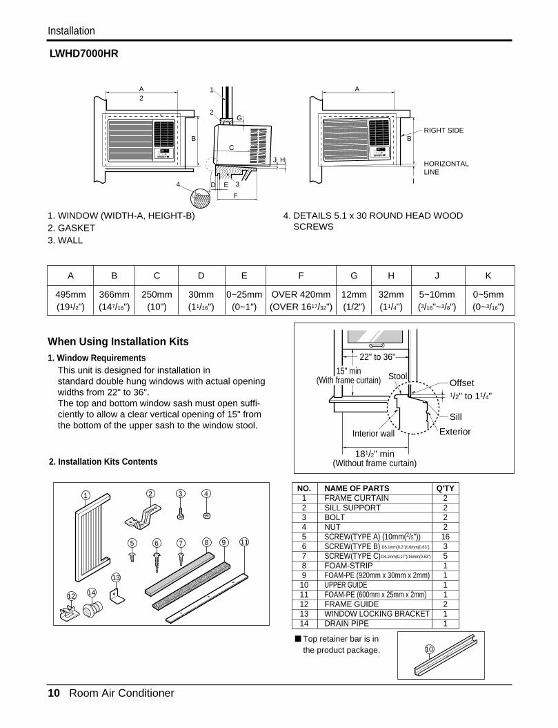
When Using Installation Kits1. Window Requirements
This unit is designed for installation in standard double hung windows with actual openingwidths from 22" to 36".The top and bottom window sash must open suffi-ciently to allow a clear vertical opening of 15" fromthe bottom of the upper sash to the window stool.
LWHD7000HR
A
B
D E
F
C
HJ
2
34
2
1
G
A
RIGHT SIDE
HORIZONTALLINE
B
I
TIMER ENERGYSAVER MODE
On/OffOn/Off Fan Cool
Heat TIMER ENERGYSAVER MODE
On/OffOn/Off Fan Cool
Heat
1. WINDOW (WIDTH-A, HEIGHT-B)2. GASKET3. WALL
4. DETAILS 5.1 x 30 ROUND HEAD WOODSCREWS
A B C D E F G H J K
495mm 366mm 250mm 30mm 0~25mm OVER 420mm 12mm 32mm 5~10mm 0~5mm(191/2") (147/16") (10") (11/16") (0~1") (OVER 1617/32") (1/2") (11/4") (3/16"~3/8") (0~3/16")
2. Installation Kits Contents
22" to 36"
Stool
Interior wall
181/2" min(Without frame curtain)
Offset1/2" to 11/4"
Sill
Exterior
15" min(With frame curtain)
1 2 3 4
8 9
14
1176
10
5
13
12
■ Top retainer bar is inthe product package.
NO. NAME OF PARTS Q'TY1 FRAME CURTAIN 22 SILL SUPPORT 23 BOLT 24 NUT 25 SCREW(TYPE A) (10mm(2/5")) 166 SCREW(TYPE B) 37 SCREW(TYPE C) 58 FOAM-STRIP 19 FOAM-PE (920mm x 30mm x 2mm) 1
10 UPPER GUIDE 111 FOAM-PE (600mm x 25mm x 2mm) 112 FRAME GUIDE 213 WINDOW LOCKING BRACKET 114 DRAIN PIPE 1
D5.1mm(0.2")/16mm(0.63")
D4.1mm(0.17")/16mm(0.63")
Service Manual 11
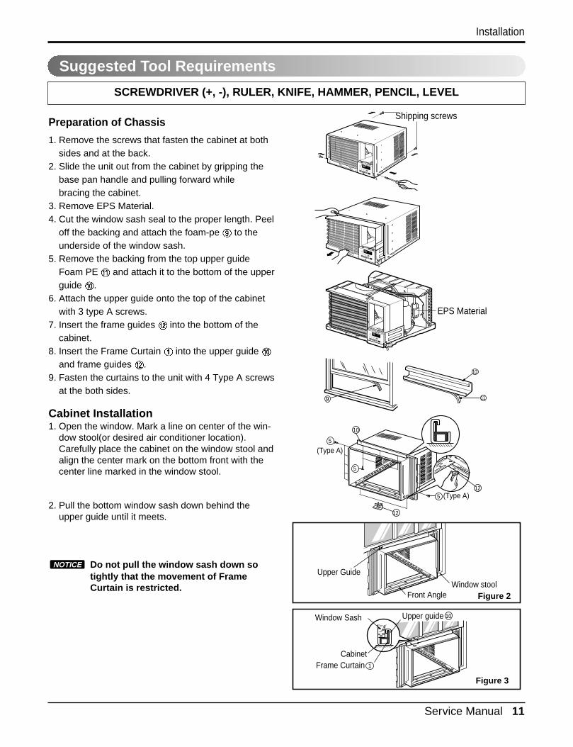
Suggested Tool Requirements
SCREWDRIVER (+, -), RULER, KNIFE, HAMMER, PENCIL, LEVEL
Preparation of Chassis
1. Remove the screws that fasten the cabinet at bothsides and at the back.
2. Slide the unit out from the cabinet by gripping thebase pan handle and pulling forward while bracing the cabinet.
3. Remove EPS Material.4. Cut the window sash seal to the proper length. Peel
off the backing and attach the foam-pe to theunderside of the window sash.
5. Remove the backing from the top upper guideFoam PE and attach it to the bottom of the upperguide .
6. Attach the upper guide onto the top of the cabinetwith 3 type A screws.
7. Insert the frame guides into the bottom of thecabinet.
8. Insert the Frame Curtain into the upper guide and frame guides .
9. Fasten the curtains to the unit with 4 Type A screwsat the both sides.
Cabinet Installation1. Open the window. Mark a line on center of the win-
dow stool(or desired air conditioner location).Carefully place the cabinet on the window stool andalign the center mark on the bottom front with thecenter line marked in the window stool.
2. Pull the bottom window sash down behind theupper guide until it meets.
Do not pull the window sash down sotightly that the movement of FrameCurtain is restricted.
NOTICE
Shipping screws
EPS Material
9
10
11
10
5
5
5
12
12
(Type A)
(Type A)
Upper Guide
Front AngleWindow stool
Upper guideWindow Sash
CabinetFrame Curtain
10
1
TIMER ENERGYSAVER MODE
On/Off
On/Off
Fan Cool
Heat
TIMER ENERGYSAVER MODE
On/Off
On/Off
Fan Cool
Heat
TIMER ENERGYSAVER MODE
On/Off
On/Off
Fan Cool
Heat
Figure 2
Figure 3
Installation
12 Room Air Conditioner
INDOOR OUTDOOR
Sill Support
NutBolt
2
43
INDOOR OUTDOOR
12
6
7
2
5Frame Guide
Abo
ut 1
/2"
Screw(Type A)
Cabinet
6
2
Abo
ut 1
/2"
Screw(Type B) 5Screw(Type A)
Sill support
Sash track
Front Angle
Type C
Screw(Type B)Sill support
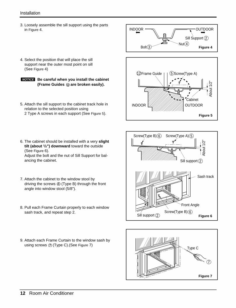
3. Loosely assemble the sill support using the partsin Figure 4.
4. Select the position that will place the sill support near the outer most point on sill(See Figure 4)
Be careful when you install the cabinet(Frame Guides are broken easily).
5. Attach the sill support to the cabinet track hole inrelation to the selected position using 2 Type A screws in each support (See Figure 5).
6. The cabinet should be installed with a very slighttilt (about 1/2") downward toward the outside (See Figure 6).Adjust the bolt and the nut of Sill Support for bal-ancing the cabinet.
7. Attach the cabinet to the window stool by driving the screws (Type B) through the frontangle into window stool (5/8").
8. Pull each Frame Curtain properly to each windowsash track, and repeat step 2.
9. Attach each Frame Curtain to the window sash byusing screws (Type C).(See Figure 7)
NOTICE
Figure 4
Figure 5
Figure 6
Figure 7
Installation

Service Manual 13
Installation
13
8Foam-Strip
Screw(Type A)
Screw(Type A)
Power cordTIMER ENERGYSAVER MODE
On/Off
On/Off
Fan Cool
Heat
TIMERENERGYSAVER
MODE
On/Off
On/Off
Fan Cool
Heat
TIMER ENERGYSAVER MODE
On/OffOn/Off Fan Cool
Heat
10. Slide the unit into the cabinet.(See Fig. 8)
CAUTION: For security purpose, reinstallscrews (Type A) at the cabinet's sides.
11. Cut the Foam-Strip to the proper length and insertbetween the upper and lower window sash.(See Fig. 9)
12. Attach the window Locking Bracket with a type Cscrew. (See Fig. 10)
13. Attach the front grille to the cabinet by inserting thetabs on the grille into the tabs on the front of the cab-inet. Push the grille in until it snaps into place.(See Fig. 11)
14. Lift the inlet grille and secure it with a type A screwthrough the front grille.(See Fig. 12)
Figure 11
Figure 8
Figure 9
Figure 10
Figure 13
Figure 12

14 Room Air Conditioner
• Designed for COOLING and HEATING.• Powerful and whispering cooling.• Slide-in and slide-out chassis for the simple instal-
lation and service.• Side air-intake, side cooled-air discharge.
• Built-in adjustable THERMOSTAT• Washable one-touch filter• Compact size• Reliable and efficient rotary compressor
Operation
Operation
Features
Control Locations Function of Controls
CLOSE VENT OPEN
Power
Temp
Fan Speed
Timer Mode
EnergySaver
1
4
2
7
3
5
Power
Temp
Fan Speed
Timer Mode
EnergySaver
AutoSwing
1
4
2
87
3
5
REMOTE CONTROLLER
16
7
54 8
2 3
TIMER ENERGYSAVER MODE
On/OffOn/Off Fan Cool
Heat
1263
4 7
5
1. POWER BUTTONTo turn the air conditioner ON, push the button. To turn theair conditioner OFF, push the button again.This button takes priority over any other buttons.
2. OPERATION MODE SELECTION BUTTONEverytime you push this button, it will toggle COOL, FANand HEAT.
3. ON/OFF TIMER BUTTONEverytime you push this button, timer is set asfollows.(1Hour ➔ 2Hours ➔ 3Hours ➔ 4Hours ➔ 5Hours➔ 6Hours ➔ 7Hours ➔ 8Hours ➔ 9Hours ➔ 10Hours ➔11Hours ➔ 12Hours ➔ Cancel)
4. FAN SPEED SELECTOREverytime you push this button, it is set as follows. (Hi[ ] ➔ Low[ ] ➔ Hi[ ]....)
5. ROOM TEMPERATURE SETTING BUTTONThis button can automatically control the temperature ofthe room. The temperature can be set within a range of60°F to 86°F by 1°F.
6. ENERGY SAVERThe fan stops when the compressor stops cooling. Approximately every 3 munutes the fan will turn on andcheck the room air to determine if cooling is needed.
7. REMOCON SIGNAL RECEIVER8. AUTO SWING
This button can automatically control the air flow direction.
CAUTION: A slight heat odor maycome from the unit when firstswitching to HEAT after the cooling
season is over. This odor, caused by finedust particles on the heater, will disappearquickly.
LWHD1200HR
LWHD1200HR LWHD7000HR
LWHD7000HR
• VENTILATIONThe ventilation lever must be in the CLOSE position inorder to maintain the best cooling conditions.When a fresh air is necessary in the room, set the ven-tilation lever to the OPEN position.The damper is opened and room air is exhausted.
Service Manual 15
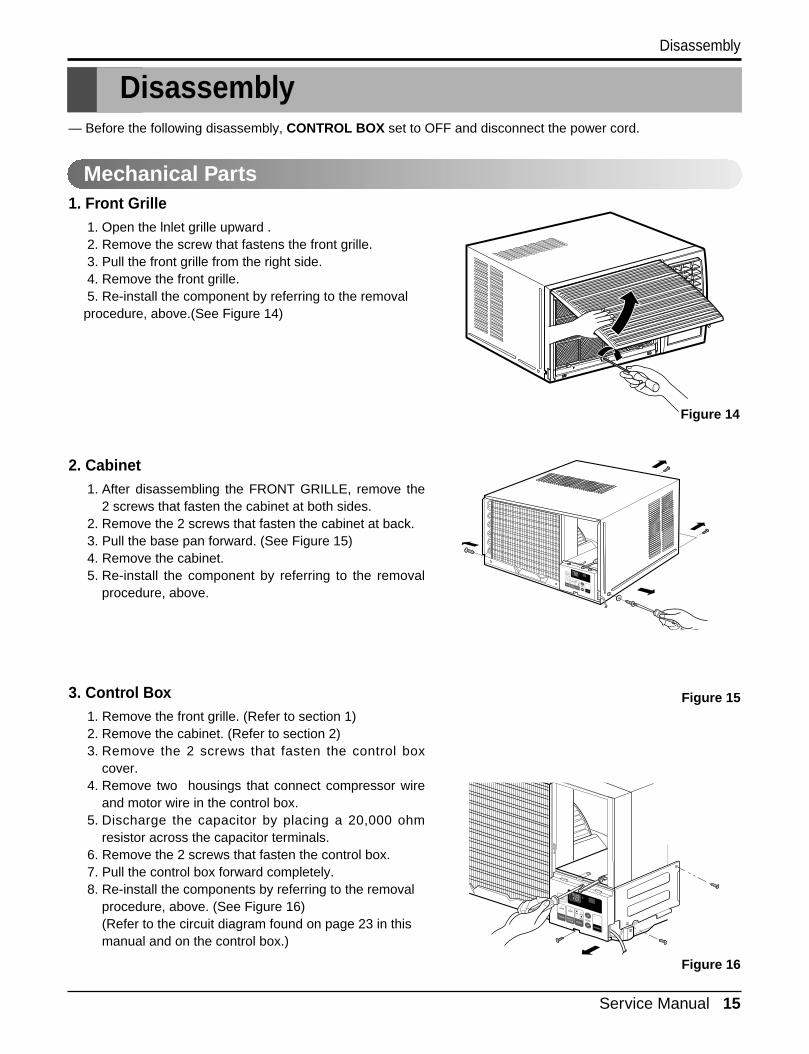
Disassembly
Disassembly
Mechanical Parts
— Before the following disassembly, CONTROL BOX set to OFF and disconnect the power cord.
1. Front Grille1. Open the lnlet grille upward .2. Remove the screw that fastens the front grille.3. Pull the front grille from the right side.4. Remove the front grille.5. Re-install the component by referring to the removalprocedure, above.(See Figure 14)
2. Cabinet1. After disassembling the FRONT GRILLE, remove the
2 screws that fasten the cabinet at both sides.2. Remove the 2 screws that fasten the cabinet at back.3. Pull the base pan forward. (See Figure 15)4. Remove the cabinet.5. Re-install the component by referring to the removal
procedure, above.
3. Control Box1. Remove the front grille. (Refer to section 1)2. Remove the cabinet. (Refer to section 2)3. Remove the 2 screws that fasten the control box
cover.4. Remove two housings that connect compressor wire
and motor wire in the control box.5. Discharge the capacitor by placing a 20,000 ohm
resistor across the capacitor terminals.6. Remove the 2 screws that fasten the control box.7. Pull the control box forward completely.8. Re-install the components by referring to the removal
procedure, above. (See Figure 16)(Refer to the circuit diagram found on page 23 in thismanual and on the control box.)
2
3
4
8
7
65
Off
MedFan
HighCool
TIMER ENERGYSAVER MODE
On/Off
On/Off
Fan Cool
Heat
TIMER ENERGYSAVER MODE
On/Off
On/Off
Fan Cool
Heat
Figure 14
Figure 16
Figure 15
16 Room Air Conditioner
Disassembly
TIMER ENERGYSAVER MODE
On/Off
On/Off
Fan Cool
Heat
Figure 17
Figure 18
Figure 19
Figure 20
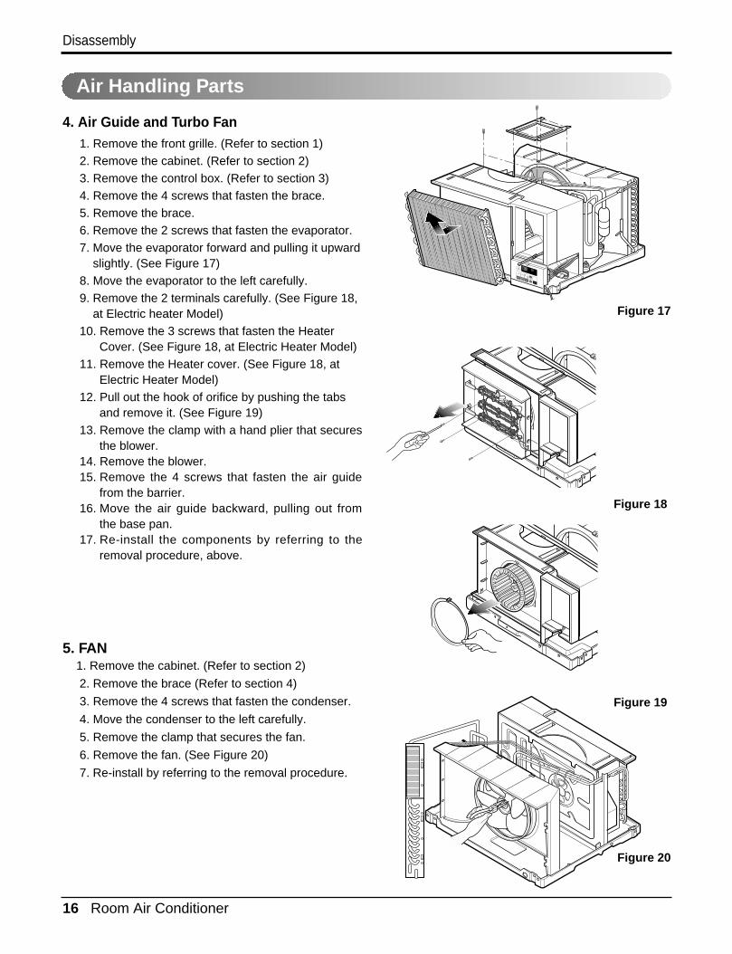
4. Air Guide and Turbo Fan1. Remove the front grille. (Refer to section 1)2. Remove the cabinet. (Refer to section 2)3. Remove the control box. (Refer to section 3)4. Remove the 4 screws that fasten the brace.5. Remove the brace.6. Remove the 2 screws that fasten the evaporator.7. Move the evaporator forward and pulling it upward
slightly. (See Figure 17)8. Move the evaporator to the left carefully. 9. Remove the 2 terminals carefully. (See Figure 18,
at Electric heater Model)10. Remove the 3 screws that fasten the Heater
Cover. (See Figure 18, at Electric Heater Model)11. Remove the Heater cover. (See Figure 18, at
Electric Heater Model)12. Pull out the hook of orifice by pushing the tabs
and remove it. (See Figure 19)13. Remove the clamp with a hand plier that secures
the blower.14. Remove the blower.15. Remove the 4 screws that fasten the air guide
from the barrier.16. Move the air guide backward, pulling out from
the base pan.17. Re-install the components by referring to the
removal procedure, above.
5. FAN1. Remove the cabinet. (Refer to section 2)
2. Remove the brace (Refer to section 4)
3. Remove the 4 screws that fasten the condenser.
4. Move the condenser to the left carefully.
5. Remove the clamp that secures the fan.
6. Remove the fan. (See Figure 20)
7. Re-install by referring to the removal procedure.
Air Handling Parts
Service Manual 17
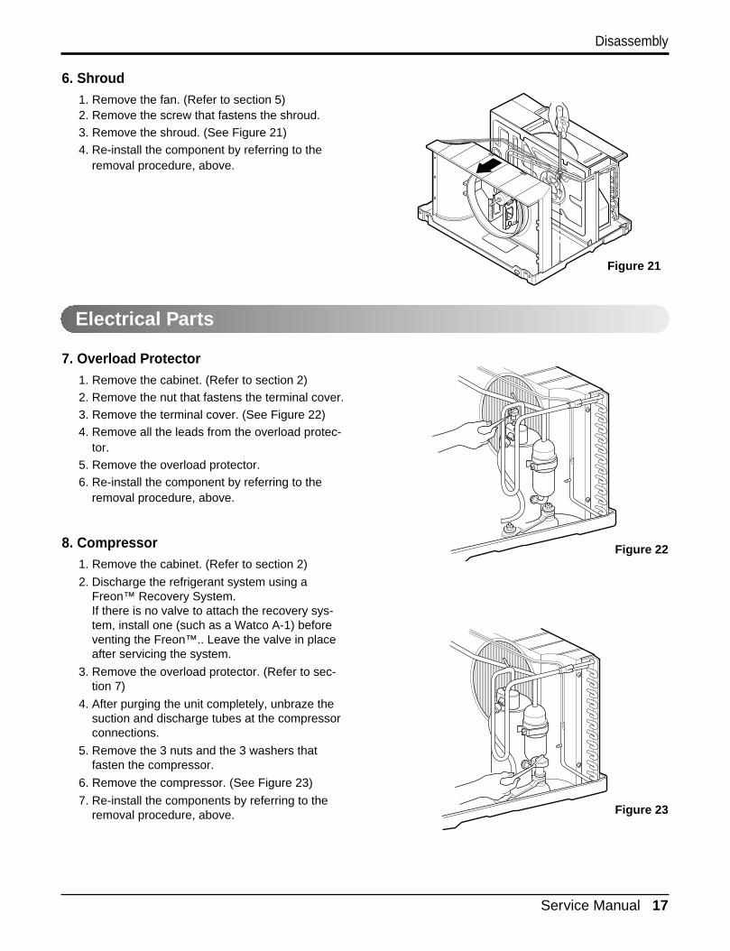
6. Shroud1. Remove the fan. (Refer to section 5)2. Remove the screw that fastens the shroud.3. Remove the shroud. (See Figure 21)4. Re-install the component by referring to the
removal procedure, above.
7. Overload Protector1. Remove the cabinet. (Refer to section 2)2. Remove the nut that fastens the terminal cover.3. Remove the terminal cover. (See Figure 22)4. Remove all the leads from the overload protec-
tor.5. Remove the overload protector.6. Re-install the component by referring to the
removal procedure, above.
8. Compressor1. Remove the cabinet. (Refer to section 2)
2. Discharge the refrigerant system using aFreon™ Recovery System.If there is no valve to attach the recovery sys-tem, install one (such as a Watco A-1) beforeventing the Freon™.. Leave the valve in placeafter servicing the system.
3. Remove the overload protector. (Refer to sec-tion 7)
4. After purging the unit completely, unbraze thesuction and discharge tubes at the compressorconnections.
5. Remove the 3 nuts and the 3 washers that fasten the compressor.
6. Remove the compressor. (See Figure 23)
7. Re-install the components by referring to theremoval procedure, above.
Disassembly
Electrical Parts
Figure 21
Figure 22
Figure 23

18 Room Air Conditioner
Disassembly
9. Capacitor1. Remove the control box. (Refer to section 3)2. Remove the knobs and the screw that fasten
control panel from control box.3. Remove the screw that located in the front.4. Open the bottom side of control box.5. Remove the screw and the clamp that fastens
the capacitor.6. Disconnect all the leads of capacitor terminals.7. Re-install the components by referring to the
removal procedure, above. (See Figure 24)
10. Power Cord1. Remove the control box. (Refer to section 3)2. Open the control box. (Refer to section 9)3. Disconnect the grounding screw from the control
box.4. Disconnect the 2 receptacles.5. Remove a screw which fastens the clip cord.
(See Figure 25)6. Remove the power cord. 7. Re-install the component by referring to the
above removal procedure, above.(Use only one ground-marked hole for groundconnection.)
8. If the supply cord of this appliance is damaged, itmust be replaced by the special cord. (The special cord means the cord that has the samespecification marked on the supply cord attachedat the unit.)
11. Thermistor1. Remove the control box. (Refer to section 3)2. Open the control box. (Refer to section 6)3. Disconnet the thermistor terminals from mainP.W.B assembly.4. Remove the thermistor.5. Re-install the components by refereing to the
above removal procedure. (See Figure 26)
12. SYNCHRONOUS MOTOR1. Remove the control box. (Refer to section 3)
2. Unfold the control box. (Refer to section 10)
3. Remove the crankshaft.
4. Disconnect all the leads of the synchronousmotor.
5. Remove the 2 screws which fasten the synchronous motor. (See Fig. 27)
6. Re-install the components by referring to theremoval procedure, above.
Figure 24
Figure 25
Figure 26
Figure 27
Service Manual 19
Disassembly
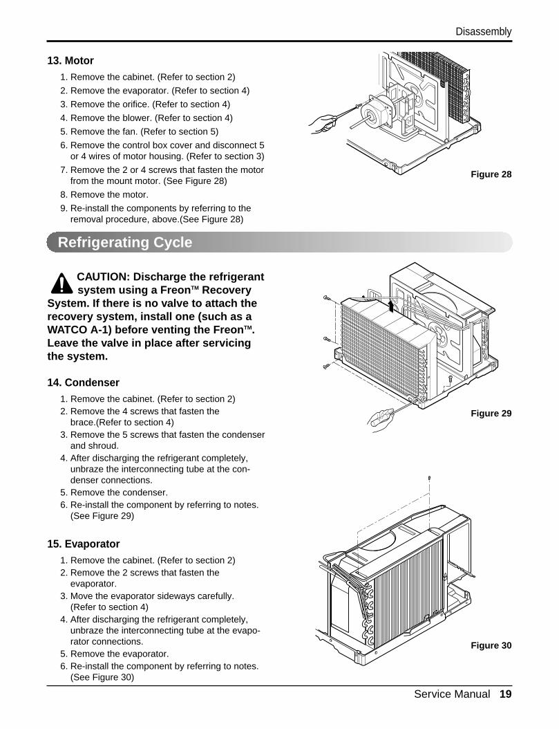
13. Motor1. Remove the cabinet. (Refer to section 2)
2. Remove the evaporator. (Refer to section 4)
3. Remove the orifice. (Refer to section 4)
4. Remove the blower. (Refer to section 4)
5. Remove the fan. (Refer to section 5)
6. Remove the control box cover and disconnect 5or 4 wires of motor housing. (Refer to section 3)
7. Remove the 2 or 4 screws that fasten the motorfrom the mount motor. (See Figure 28)
8. Remove the motor.
9. Re-install the components by referring to theremoval procedure, above.(See Figure 28)
CAUTION: Discharge the refrigerantsystem using a FreonTM Recovery
System. If there is no valve to attach therecovery system, install one (such as aWATCO A-1) before venting the FreonTM.Leave the valve in place after servicingthe system.
14. Condenser1. Remove the cabinet. (Refer to section 2)2. Remove the 4 screws that fasten the
brace.(Refer to section 4)3. Remove the 5 screws that fasten the condenser
and shroud.4. After discharging the refrigerant completely,
unbraze the interconnecting tube at the con-denser connections.
5. Remove the condenser.6. Re-install the component by referring to notes.
(See Figure 29)
15. Evaporator1. Remove the cabinet. (Refer to section 2)2. Remove the 2 screws that fasten the
evaporator.3. Move the evaporator sideways carefully.
(Refer to section 4)4. After discharging the refrigerant completely,
unbraze the interconnecting tube at the evapo-rator connections.
5. Remove the evaporator.6. Re-install the component by referring to notes.
(See Figure 30)
Figure 28
Figure 29
Figure 30
Refrigerating Cycle

20 Room Air Conditioner
Disassembly
— Replacement of the refrigeration cycle.1. When replacing the refrigeration cycle, be sure to
Discharge the refrigerant system using a FreonTM
recovery System.If there is no valve to attach the recovery system,install one (such as a WATCO A-1) before ventingthe FreonTM. Leave the valve in place after servicing the system.
2. After discharging the unit completely, remove thedesired component, and unbraze the pinch-offtubes.
3. Solder service valves into the pinch-off tube ports,leaving the valves open.
4. Solder the pinch-off tubes with Service valves.5. Evacuate as follows.
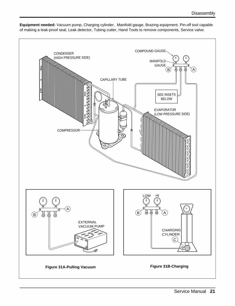
1) Connect the vacuum pump, as illustrated figure31A.
2) Start the vacuum pump, slowly open manifold valves A and B with two full turns counterclock-wise and leave the valves open.The vacuum pump is now pulling through valvesA and B up to valve C by means of the manifoldand entire system.
CAUTION: If high vacuum equip-ment is used, just crack valves A
and B for a few minutes, then open slowlywith the two full turns counterclockwise.This will keep oil from foaming and beingdrawn into the vacuum pump.
3) Operate the vacuum pump vaccum for 20 to 30minutes, until 600 microns of vaccum isobtained. Close valves A and B, and observevacuum gauge for a few minutes. A rise inpressure would indicate a possible leak ormoisture remaining in the system. With valvesA and B closed, stop the vacuum pump.
4) Remove the hose from the vacuum pump andplace it on the charging cylinder. See figure31B. Open valve C.Discharge the line at the manifold connection.
5) The system is now ready for final charging.
6. Recharge as follows :1) Refrigeration cycle systems are charged from
the High-side. If the total charge cannot be put in the High-side, the balance will be put in the suction line through the access valve which you installed as the system was opened.
2) Connect the charging cylinder as shown in fig-ure 31B.With valve C open, discharge the hose at themanifold connection.
3) Open valve A and allow the proper charge to enter the system. Valve B is still closed.
4) If more charge is required, the high-side will not take it. Close valve A.
5) With the unit running, open valve B and add the balance of the charge.a. Do not add the liquid refrigerant to the Low-
side.b. Watch the Low-side gauge; allow pressure to
rise to 30 lbs.c. Turn off valve B and allow pressure to drop.d. Repeat steps b. and c. until the balance of the
charge is in the system.6) When satisfied the unit is operating correctly,
use the pinch-off tool with the unit still running and clamp on to the pinch-off tube. Using a tube cutter, cut the pinch-off tube about 2 inchesfrom the pinch-off tool. Use sil-fos braze andbraze pinch-off tube closed. Turn off the unit,allow it to set for a while, and then test the leak-age of the pinch-off connection.
16. Capillary Tube1. Remove the cabinet. (Refer to section 2)2. After discharging the refrigerant completely,
unbraze the interconnecting tube at the capil-lary tube.(See caution above)
3. Remove the capillary tube.4. Re-install the component by referring to notes.
NOTICE
Service Manual 21
Disassembly
Equipment needed: Vacuum pump, Charging cylinder, Manifold gauge, Brazing equipment. Pin-off tool capableof making a leak-proof seal, Leak detector, Tubing cutter, Hand Tools to remove components, Service valve.
A
COMPOUND GAUGE
EVAPORATOR(LOW PRESSURE SIDE)
COMPRESSOR
CAPILLARY TUBE
CONDENSER(HIGH PRESSURE SIDE)
SEE INSETSBELOW
MANIFOLDGAUGE
B
Figure 31A-Pulling Vacuum Figure 31B-Charging
A
B
EXTERNALVACUUM PUMP
A
CHARGINGCYLINDER
LOW HI
B
C
22 Room Air Conditioner
Schematic Diagram
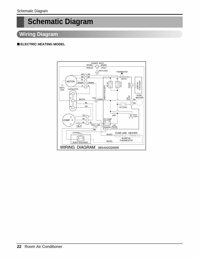
Schematic Diagram
Wiring Diagram
■ ELECTRIC HEATING MODEL
Service Manual 23
Troubleshooting Guide
Troubleshooting Guide
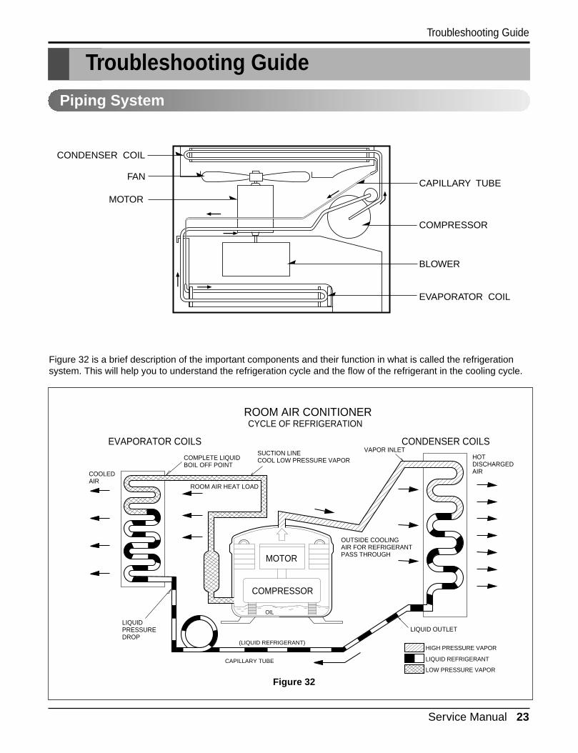
Piping System
Figure 32 is a brief description of the important components and their function in what is called the refrigerationsystem. This will help you to understand the refrigeration cycle and the flow of the refrigerant in the cooling cycle.
MOTOR
COMPRESSOR
OIL
(LIQUID REFRIGERANT)
CAPILLARY TUBE
OUTSIDE COOLINGAIR FOR REFRIGERANTPASS THROUGH
SUCTION LINECOOL LOW PRESSURE VAPOR
COOLEDAIR
COMPLETE LIQUIDBOIL OFF POINT
LIQUIDPRESSUREDROP
ROOM AIR HEAT LOAD
VAPOR INLETHOTDISCHARGEDAIR
LIQUID OUTLET
HIGH PRESSURE VAPOR
LIQUID REFRIGERANT
LOW PRESSURE VAPOR
ROOM AIR CONITIONER
EVAPORATOR COILS CONDENSER COILS
CYCLE OF REFRIGERATION
CAPILLARY TUBE
COMPRESSOR
BLOWER
EVAPORATOR COIL
CONDENSER COIL
FAN
MOTOR
Figure 32
24 Room Air Conditioner
Troubleshooting Guide
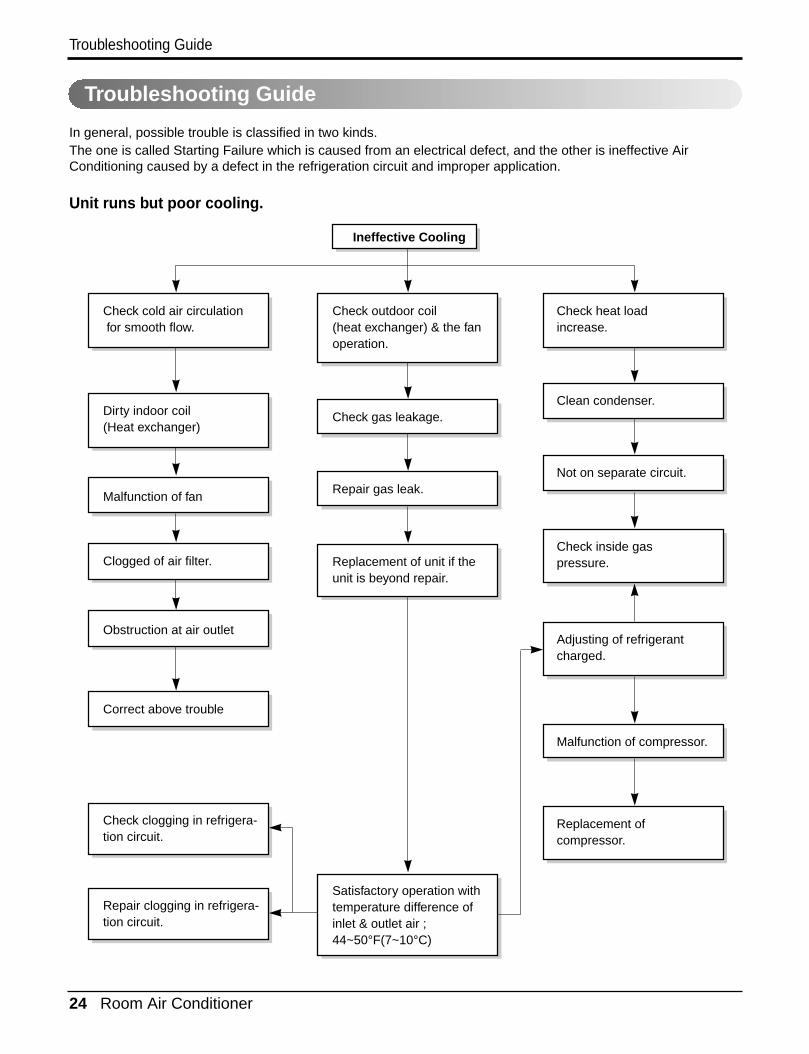
Troubleshooting Guide
In general, possible trouble is classified in two kinds.The one is called Starting Failure which is caused from an electrical defect, and the other is ineffective AirConditioning caused by a defect in the refrigeration circuit and improper application.
Unit runs but poor cooling.
Ineffective Cooling
Check outdoor coil(heat exchanger) & the fanoperation.
Check gas leakage.
Repair gas leak.
Replacement of unit if theunit is beyond repair.
Satisfactory operation withtemperature difference ofinlet & outlet air ; 44~50°F(7~10°C)
Check heat load increase.
Clean condenser.
Not on separate circuit.
Check inside gaspressure.
Adjusting of refrigerantcharged.
Malfunction of compressor.
Replacement ofcompressor.
Check cold air circulation for smooth flow.
Dirty indoor coil(Heat exchanger)
Correct above trouble
Check clogging in refrigera-tion circuit.
Repair clogging in refrigera-tion circuit.
Obstruction at air outlet
Clogged of air filter.
Malfunction of fan
Service Manual 25
Troubleshooting Guide
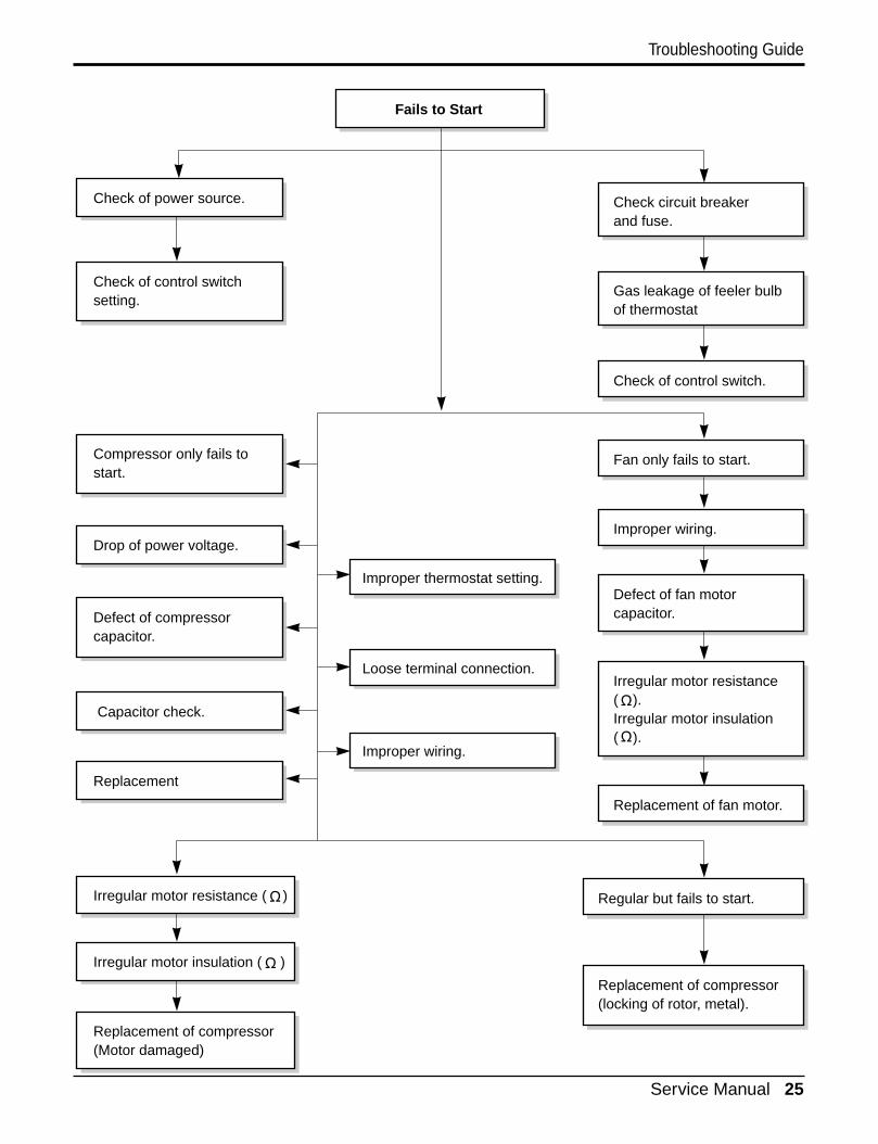
Fails to Start
Check circuit breakerand fuse.
Gas leakage of feeler bulbof thermostat
Check of control switch.
Fan only fails to start.
Improper wiring.
Defect of fan motorcapacitor.
Irregular motor resistance( ).Irregular motor insulation( ).
Replacement of fan motor.
Regular but fails to start.
Replacement of compressor(locking of rotor, metal).
Improper thermostat setting.
Loose terminal connection.
Improper wiring.
Irregular motor resistance ( )
Irregular motor insulation ( )
Replacement of compressor(Motor damaged)
Drop of power voltage.
Capacitor check.
Replacement
Compressor only fails tostart.
Defect of compressorcapacitor.
Check of power source.
Check of control switchsetting.
26 Room Air Conditioner
Troubleshooting Guide
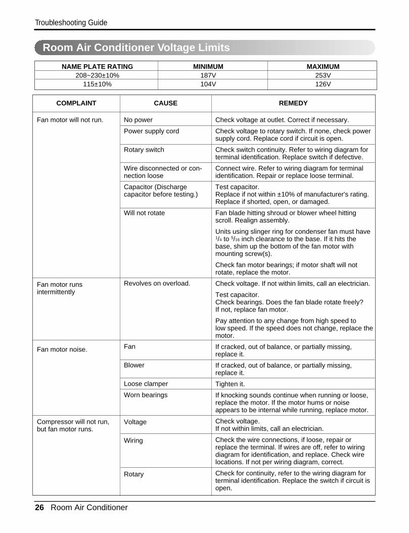
COMPLAINT CAUSE REMEDY
Check voltage at outlet. Correct if necessary.
Check voltage to rotary switch. If none, check powersupply cord. Replace cord if circuit is open.
Check switch continuity. Refer to wiring diagram forterminal identification. Replace switch if defective.
Connect wire. Refer to wiring diagram for terminalidentification. Repair or replace loose terminal.
Test capacitor.Replace if not within ±10% of manufacturer's rating.Replace if shorted, open, or damaged.
Fan blade hitting shroud or blower wheel hittingscroll. Realign assembly.
Units using slinger ring for condenser fan must have1/4 to 5/16 inch clearance to the base. If it hits thebase, shim up the bottom of the fan motor withmounting screw(s).
Check fan motor bearings; if motor shaft will notrotate, replace the motor.
Check voltage. If not within limits, call an electrician.
Test capacitor.Check bearings. Does the fan blade rotate freely?If not, replace fan motor.
Pay attention to any change from high speed tolow speed. If the speed does not change, replace themotor.
If cracked, out of balance, or partially missing,replace it.
If cracked, out of balance, or partially missing,replace it.
Tighten it.
If knocking sounds continue when running or loose,replace the motor. If the motor hums or noiseappears to be internal while running, replace motor.
Check voltage. If not within limits, call an electrician.
Check the wire connections, if loose, repair orreplace the terminal. If wires are off, refer to wiringdiagram for identification, and replace. Check wirelocations. If not per wiring diagram, correct.
Check for continuity, refer to the wiring diagram forterminal identification. Replace the switch if circuit isopen.
No power
Power supply cord
Rotary switch
Wire disconnected or con-nection loose
Capacitor (Dischargecapacitor before testing.)
Will not rotate
Revolves on overload.
Fan
Blower
Loose clamper
Worn bearings
Voltage
Wiring
Rotary
Fan motor will not run.
Fan motor runs intermittently
Fan motor noise.
Compressor will not run,but fan motor runs.
NAME PLATE RATING MINIMUM MAXIMUM208~230±10% 187V 253V
115±10% 104V 126V
Room Air Conditioner Voltage Limits
Service Manual 27
Troubleshooting Guide
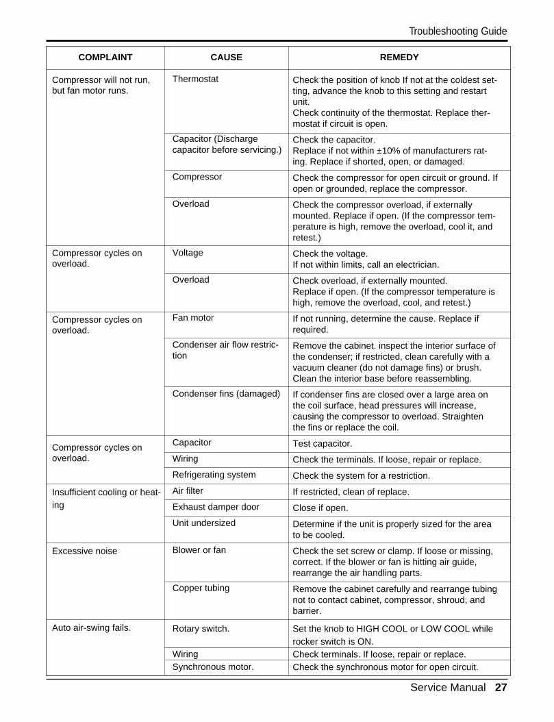
COMPLAINT CAUSE REMEDY
Check the position of knob If not at the coldest set-ting, advance the knob to this setting and restartunit.Check continuity of the thermostat. Replace ther-mostat if circuit is open.
Check the capacitor.Replace if not within ±10% of manufacturers rat-ing. Replace if shorted, open, or damaged.
Check the compressor for open circuit or ground. Ifopen or grounded, replace the compressor.
Check the compressor overload, if externallymounted. Replace if open. (If the compressor tem-perature is high, remove the overload, cool it, andretest.)
Check the voltage.If not within limits, call an electrician.
Check overload, if externally mounted.Replace if open. (If the compressor temperature ishigh, remove the overload, cool, and retest.)
If not running, determine the cause. Replace ifrequired.
Remove the cabinet. inspect the interior surface ofthe condenser; if restricted, clean carefully with avacuum cleaner (do not damage fins) or brush.Clean the interior base before reassembling.
If condenser fins are closed over a large area onthe coil surface, head pressures will increase,causing the compressor to overload. Straightenthe fins or replace the coil.
Test capacitor.
Check the terminals. If loose, repair or replace.
Check the system for a restriction.
If restricted, clean of replace.
Close if open.
Determine if the unit is properly sized for the areato be cooled.
Check the set screw or clamp. If loose or missing,correct. If the blower or fan is hitting air guide,rearrange the air handling parts.
Remove the cabinet carefully and rearrange tubingnot to contact cabinet, compressor, shroud, andbarrier.
Set the knob to HIGH COOL or LOW COOL whilerocker switch is ON.Check terminals. If loose, repair or replace.Check the synchronous motor for open circuit.
Thermostat
Capacitor (Dischargecapacitor before servicing.)
Compressor
Overload
Voltage
Overload
Fan motor
Condenser air flow restric-tion
Condenser fins (damaged)
Capacitor
Wiring
Refrigerating system
Air filter
Exhaust damper door
Unit undersized
Blower or fan
Copper tubing
Rotary switch.
WiringSynchronous motor.
Compressor will not run,but fan motor runs.
Compressor cycles onoverload.
Compressor cycles onoverload.
Compressor cycles onoverload.
Insufficient cooling or heat-ing
Excessive noise
Auto air-swing fails.

28 Room Air Conditioner
Exploded View
Exploded View
147582
359012
135303
W52106-1W52106-2
559010
264110
249950
263230
267110
238310
237200 268714
W0CZZ
135500268712
753010
352111552101
753000
TIMER ENERGYSAVER MODE
On/Off
On/Off
FanCoolHeat
552206
Service Manual 29
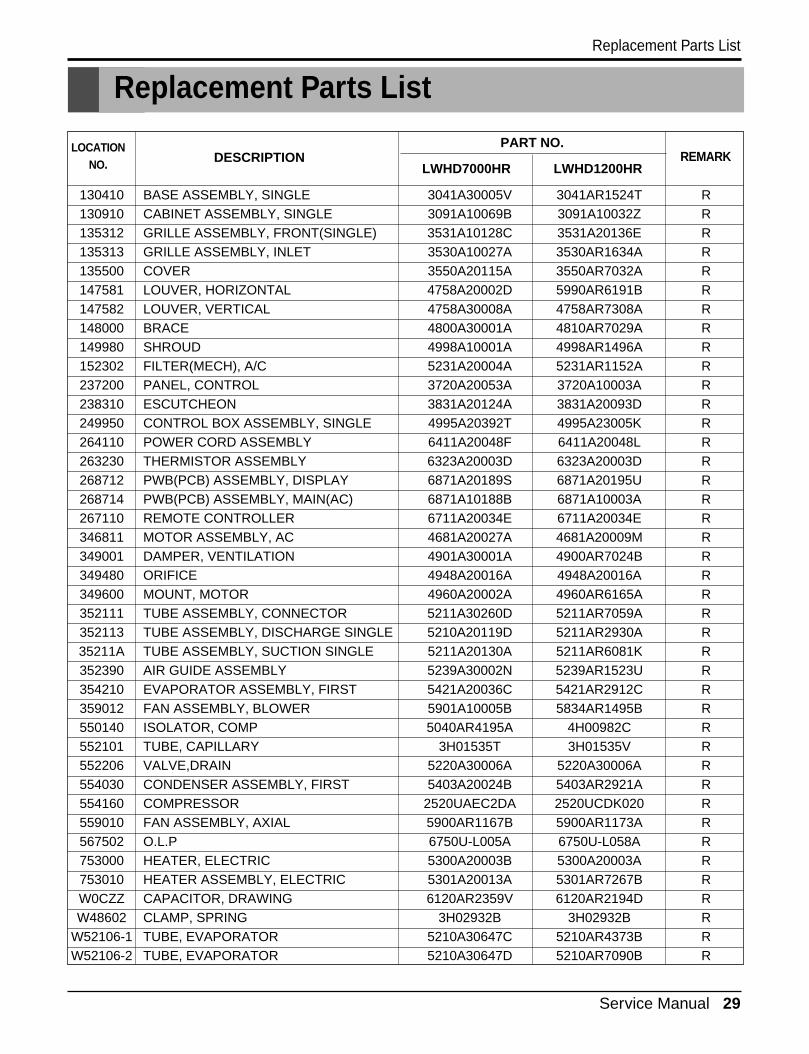
Replacement Parts ListReplacement Parts List
130410 BASE ASSEMBLY, SINGLE 3041A30005V 3041AR1524T R130910 CABINET ASSEMBLY, SINGLE 3091A10069B 3091A10032Z R135312 GRILLE ASSEMBLY, FRONT(SINGLE) 3531A10128C 3531A20136E R135313 GRILLE ASSEMBLY, INLET 3530A10027A 3530AR1634A R135500 COVER 3550A20115A 3550AR7032A R147581 LOUVER, HORIZONTAL 4758A20002D 5990AR6191B R147582 LOUVER, VERTICAL 4758A30008A 4758AR7308A R148000 BRACE 4800A30001A 4810AR7029A R149980 SHROUD 4998A10001A 4998AR1496A R152302 FILTER(MECH), A/C 5231A20004A 5231AR1152A R237200 PANEL, CONTROL 3720A20053A 3720A10003A R238310 ESCUTCHEON 3831A20124A 3831A20093D R249950 CONTROL BOX ASSEMBLY, SINGLE 4995A20392T 4995A23005K R264110 POWER CORD ASSEMBLY 6411A20048F 6411A20048L R263230 THERMISTOR ASSEMBLY 6323A20003D 6323A20003D R268712 PWB(PCB) ASSEMBLY, DISPLAY 6871A20189S 6871A20195U R268714 PWB(PCB) ASSEMBLY, MAIN(AC) 6871A10188B 6871A10003A R267110 REMOTE CONTROLLER 6711A20034E 6711A20034E R346811 MOTOR ASSEMBLY, AC 4681A20027A 4681A20009M R349001 DAMPER, VENTILATION 4901A30001A 4900AR7024B R349480 ORIFICE 4948A20016A 4948A20016A R349600 MOUNT, MOTOR 4960A20002A 4960AR6165A R352111 TUBE ASSEMBLY, CONNECTOR 5211A30260D 5211AR7059A R352113 TUBE ASSEMBLY, DISCHARGE SINGLE 5210A20119D 5211AR2930A R35211A TUBE ASSEMBLY, SUCTION SINGLE 5211A20130A 5211AR6081K R352390 AIR GUIDE ASSEMBLY 5239A30002N 5239AR1523U R354210 EVAPORATOR ASSEMBLY, FIRST 5421A20036C 5421AR2912C R359012 FAN ASSEMBLY, BLOWER 5901A10005B 5834AR1495B R550140 ISOLATOR, COMP 5040AR4195A 4H00982C R552101 TUBE, CAPILLARY 3H01535T 3H01535V R552206 VALVE,DRAIN 5220A30006A 5220A30006A R554030 CONDENSER ASSEMBLY, FIRST 5403A20024B 5403AR2921A R554160 COMPRESSOR 2520UAEC2DA 2520UCDK020 R559010 FAN ASSEMBLY, AXIAL 5900AR1167B 5900AR1173A R567502 O.L.P 6750U-L005A 6750U-L058A R753000 HEATER, ELECTRIC 5300A20003B 5300A20003A R753010 HEATER ASSEMBLY, ELECTRIC 5301A20013A 5301AR7267B RW0CZZ CAPACITOR, DRAWING 6120AR2359V 6120AR2194D RW48602 CLAMP, SPRING 3H02932B 3H02932B R
W52106-1 TUBE, EVAPORATOR 5210A30647C 5210AR4373B RW52106-2 TUBE, EVAPORATOR 5210A30647D 5210AR7090B R
DESCRIPTIONPART NO.
REMARKLWHD7000HR LWHD1200HR
LOCATIONNO.

P/No.: 3828A20841AMay, 2006
Printed in Korea