rooftop equipment supports - rci, inc.rci-online.org/wp-content/uploads/2009-10-schaack.pdfsome...
TRANSCRIPT
Rooftops have commonly been used as a haven for the installation of various pieces of equipment with the mentality, “We have nowhere else to put them,” or “Let’s just
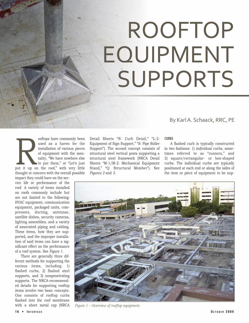
put it up on the roof,” with very little thought or concern with the overall possible impact they could have on the service life or performance of the roof. A variety of items installed on roofs commonly include but are not limited to the following: HVAC equipment, communication equipment, packaged units, compressors, ducting, antennae, satellite dishes, security cameras, lighting assemblies, and a variety of associated piping and cabling. These items, how they are supported, and the improper installation of said items can have a significant effect on the performance of a roof system. See Figure 1.
There are generally three different methods for supporting the various items, including: 1) flashed curbs, 2) flashed steel supports, and 3) nonpenetrating supports. The NRCA-recommended details for supporting rooftop items involve two basic concepts. One consists of rooftop curbs flashed into the roof membrane with a sheet metal cap (NRCA
Detail Sheets “N: Curb Detail,” “L-2: Equipment of Sign Support,” “S: Pipe Roller Support”). The second concept consists of structural steel vertical posts supporting a structural steel framework (NRCA Detail Sheets “M-1/M-2: Mechanical Equipment Stand,” “Q: Structural Member”). See Figures 2 and 3.
CURBS A flashed curb is typically constructed
in two fashions: 1) individual curbs, sometimes referred to as “runners,” and 2) square/rectangular- or box-shaped curbs. The individual curbs are typically positioned at each end or along the sides of the item or piece of equipment to be sup-
Figure 1 – Overview of rooftop equipment.
1 6 • I N T E R F A C E O C T O B E R 2 0 0 9

Figure 2 – NRCA Detail M-2.
ported (Figure 4). An additional individual curb can also be positioned at mid-span of the item, depending on its actual size or weight. For rooftop piping, the individual curbs are typically positioned approximately 5 to 10 ft on-center. The pipes are either placed directly on top of the curbs or on some type of steel support structure such as a roller or saddle that is anchored to the top of the curb.
When installed by a roofing contractor, the curbs can be constructed in the field using 2x dimensional lumber or shop-fabricated sheet metal. Pre man ufactured curbs constructed from sheet metal (commonly 16 gauge) are also readily available from various suppliers. These types of curbs are commonly made from galvanized sheet
Figure 3 – NRCA Detail Q.
Figure 4 – Equipment installed on curbs/runners.
O C T O B E R 2 0 0 9 I N T E R F A C E • 1 7
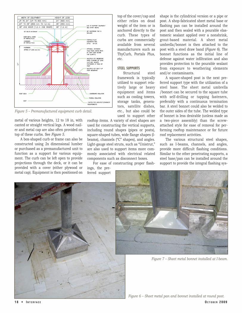
Figure 5 – Premanufactured equipment curb detail.
top of the cover/cap and either relies on dead weight of the item or is anchored directly to the curb. These types of curbs are commercially available from several manufacturers such as ThyCurb, Portals Plus, etc.
STEEL SUPPORTS Structural steel
framework is typically utilized to support relatively large or heavy equipment and items such as cooling towers, storage tanks, generators, satellite dishes, etc., but also could be used to support other
rooftop items. A variety of steel shapes are used for constructing the vertical supports, including round shapes (pipes or posts), square-shaped tubes, wide flange shapes (Ibeams), channels (“C” shapes), and angles. Light-gauge steel struts, such as “Unistrut,” are also used to support items more commonly associated with electrical related components such as disconnect boxes.
For ease of constructing proper flashings, the preferred support
metal of various heights, 12 to 18 in, with canted or straight vertical legs. A wood nailer and metal cap are also often provided on top of these curbs. See Figure 5.
A box-shaped curb or frame can also be constructed using 2x dimensional lumber or purchased as a premanufactured unit to function as a support for various equipment. The curb can be left open to provide projections through the deck, or it can be provided with a cover (either plywood or metal cap). Equipment is then positioned on
shape is the cylindrical version or a pipe or post. A shop-fabricated sheet metal base or flashing pan can be installed around the post and then sealed with a pourable elastomeric sealant applied over a nonshrink, grout-based material. A sheet metal umbrella/bonnet is then attached to the post with a steel draw band (Figure 6). The bonnet functions as the initial line of defense against water infiltration and also provides protection to the pourable sealant from exposure to weathering elements and/or contaminants.
A square-shaped post is the next preferred support type with the utilization of a steel base. The sheet metal umbrella /bonnet can be secured to the square tube with self-drilling or tapping fasteners, preferably with a continuous termination bar. A steel bonnet could also be welded to the outer sides of the tube. The welded type of bonnet is less desirable (unless made as a two-piece assembly) than the screw-attached style for ease of removal for performing rooftop maintenance or for future roof replacement activities.
The various structural steel shapes, such as I-beams, channels, and angles, provide more difficult flashing conditions. Similar to the other penetrating supports, a steel base/pan can be installed around the support to provide the integral flashing sys
1 8 • I N T E R F A C E O C T O B E R 2 0 0 9
Figure 7 – Sheet metal bonnet installed at I-beam.
Figure 6 – Sheet metal pan and bonnet installed at round post.

Figure 8 – Pre-manufactured penetration seal (“doughnut”) installed at steel support.
tem into the roof membrane, and a steel bonnet can be welded to the support (Figure 7). Several manufacturers, such as Portals Plus, SBS Industries, etc., offer specialty products that are produced to provide pre-manufactured flashing assemblies around these difficult shapes. The two-piece sheet metal flashing assembly is recommended regardless of the shape of the penetrating support.
Other products have been developed and promoted to provide options for constructing flashings around various penetrating supports. One of these products consists of premolded, rubber/polymercomposite, two-piece interlocking curbs or “doughnuts.” The doughnut is placed in sealant directly on top of the roof membrane surface and encircles the penetrating element. An elastomeric filler or pourable sealer is then installed within the doughnut in a fashion similar to that of a pitch pan (Figure 8). Since the sealer within the
assembly remains exposed, achieving a proper bond of the sealant to the penetrating element is critical for long-term, watertight performance. Manufacturers of this type of system include Chem-Link’s “Chem-Curb” and Millenium’s “Lockin Pocket.”
Another available flashing system consists of a liquid-applied coating, together with a reinforcing fabric. This system involves applying the coating system (liquid coating and embedded fabric) to the penetrating element and onto the roof membrane surface around the penetration to form a monolithic seal (Figure 9). Commonly
Figure 9 – Liquid flashing membrane installed at steel support.
O C T O B E R 2 0 0 9 I N T E R F A C E • 1 9

Figure 10 – Equipment installed on top of 4x4 wood sleeper.
available systems include “TeraPro” by Siplast, “Kemperol” by Kemper, and “Alsan” by Soprema. It may be possible that the coating flashing systems and the penetration pockets can be included in the coverage of the roof system warranty that would be provided by the roofing material manufacturer.
NONPENETRATING SUPPORTS Another option for supporting various
rooftop items is assemblies that do not penetrate the roof membrane, commonly referred to as nonpenetrating supports.
These supports range from basic wood blocking to engineered, pre-manufactured, steel strut assemblies. These nonpenetrating elements are placed on top of the roof surface with some type of protection/separation pad typically placed between the bottom of the support and the actual surface of the roof membrane/covering. Four-by-four di mensional treated or redwood lumber blocking is typically used and cut to a specific length to suit the application. Two-by-four dimensional treated lumber, stacked or individually, can also
be utilized. When utilized as a pipe support, the pipes are placed directly on top of the blocking and then sometimes secured in place with a sheet metal strap (i.e. conduit clamp or shop-fabricated metal straps). Wood blocking is commonly used to support rooftop piping such as electrical conduits, condensate drain pipes, gas pipes, and equipment. Wood blocking is also used to support other rooftop equipment, such as condensers, packaged units, etc. (Figure 10). Some obvious issues associated with wood blocking include deterioration and warping of the wood. Additionally, wood blocking will typically not allow for adequate movement and/or load distribution, which can result in damage to the roof, even with the installation of protection pads (Figure 11).
A wide variety of pre-manufactured, nonpenetrating assemblies is also available, ranging in style and materials. Some common
available products include ABS plastic saddles, sheet metal discs, and steel strut assemblies. These supports can be provided
Figure 12 – Typical pre-manufactured pipe
support detail.
Figure 11 – Damage to roof from movement of piping and support.
2 0 • I N T E R F A C E O C T O B E R 2 0 0 9

with either a bar or roller component to support the respective piping (Figure 12).
For larger types of pipes, such as insulated hot-water pipes, assemblies can be constructed in a standlike fashion with clevis, rollers, or saddle hangers suspended with threaded rods. The stands are commonly constructed with C-shaped steel struts (UniStrut) assembled with horizontal cross members and vertical support posts that are adjoined with brackets, angles, and/or gusset plates and installed with some type of prefabricated base to support the equipment and distribute the loads on the roof.
Assemblies are also available to support the various types of equipment that are often encountered on rooftops (Figure 13). Walkways, stair assemblies, crossovers, and assorted types of stands are available or can be customized to suit the application. These assemblies can be viewed as similar to erector sets for the roofing industry. A unique feature of the strut assemblies is the ability to customize each individual support to suit the existing size, number, direction, and/or configuration of the piping/equipment and rooftop conditions. These assemblies can also be engineered in
Figure 13 – Mechanical equipment installed on pre-manufactured support.
order to provide suitable support for the SUMMARY respective item while minimizing the impact The decision to use curbs, penetrating on the roof (Figure 14). steel supports, or nonpenetrating supports
depends on several variables, including but
O C T O B E R 2 0 0 9 I N T E R F A C E • 2 1

involved.
Figure 14 – Satellite dish installed on premanufactured support.
not limited to the following: budget constraints, anticipated load capacity, owner and project requirements (wind/seismic loading), designer or installer preferences, and site constraints or limitations.
Some common issues regarding penetrating supports include:
1) Creation of additional penetrations in the roof membrane results in additional potential leak sources.
2) These types of supports are less flexible in regard to modifications or changes associated with adding, eliminating, or revising the piping and/or equipment.
3) This type of assembly can provide structurally sound supports for the piping/equipment that can adequately handle the necessary dead loads or seismic loads and/or move-ment/vibrations.
3) These supports can be readily rearranged and/or modified to adapt to changes in the piping and equipment.
4) The more “sophisticated” assemblies can be engineered to meet the necessary loading requirements or load distribution and can be installed directly by the manufacturer’s personnel.
Over the past 10 years, the roofing industry has experienced a proliferation of a wide variety of products, assemblies, materials, and/or systems to offer solutions for supporting equipment and/or flashings of such supports. Whichever system or option is selected for supporting rooftop items and their related flashings should be properly designed, installed, and maintained in order to provide optimum solutions with
Common issues related to the nonpene the least impact to the roof covering. Just trating supports are: as with roofing materials, improper installa
1) Some of these assemblies (i.e., wood tion can result in physical damage to the blocking) typically cannot allow for roof covering, resulting in moisture infiltraproper movement of piping, conse tion. quently resulting in possible damage to the underlying membrane. REFERENCE
2) These supports may not provide NRCA Roofing & Waterproofing Manualproper capacity for the element
Karl A. Schaack, RRC, PE
Karl A. Schaack, RRC, PE, is president of Price Consulting, Inc., a roofing and waterproofing consulting firm in Houston, Texas. Mr. Schaack has a bachelor’s degree in civil engineering from Clemson University. He is a registered professional engineer in Texas, South Carolina, and North Carolina. Karl is a member of RCI, the Roofing Contractors Association of Texas, and the Gulf Coast Chapter of RCI. Karl is a former director of RCI’s original Region IV and was the 2007 recipient of RCI’s prestigious Richard M. Horowitz Award for outstanding contribution to Interface journal.
2 2 • I N T E R F A C E O C T O B E R 2 0 0 9