rolls-royce silver shadow, long wheelbase, corniche and...
TRANSCRIPT
Service Bulletins 1976-1978
-Rolls-Royce Silver Shadow,
Long Wheelbase, Corniche and Camargue.
Bentley T Series and C:orniche Rolls-Royce Silver Shadow II
and Silver Wraith II Bentley T2
T.S.D. Publication 4171
...
Printed and Published by Rolls-Royea Motor Cars Limited
Crewe Cheshire CW1 3PL England
This publication Is a reprint of the original. Whilst the information is given in good faith Rolls-Royce
Motor Cars Limited gives no warranty or representation concerning the information and such information must not be taken as forming part of or establishing any contractual or other
commitment by Rolls-Royce Motor Cars Limited
c Rolls-Royce Motors Limited 1976
Reprinted by Rolls-Royce Motor Cars Limited 1988

Service Bulletins
Contents 1 l .s J C
cf A General Information
B Special Processes
C Air Conditioning
D Lubrication and Maintenance
E Engine
F Propeller Shaft and Universal Joint•
G Hydraulic Systems co ~
H Sub-frames and Suspension -i ~ J Final Orlve :1 ! K Fuel System and Carburette~s B i L Engine Cooling System
I M Electrical System
i N Power Assisted Steering
® p Torque Tightening Figures
Q Exhaust System
A Wheels and Tyres
s Body
T Transmission
u Emission Control Systems
PVI Phantom VI

Service Bulletin
Bulletin number Index
Circulation list
Category All Franchise Holders
r I
Service Bulletin Index for T.S.D. 4171
Applicable To:
Date
II II 11
·31 12 78 Page
11 11 I
ID)OLLS· ft\\OYCE MOTORS
Car Division
TSO 4171
1 of 3
I I
Rolls•Royce Silver Shadow, Rolls•Royce Long Wheelbase. Bentley T Series, Rolls-Royce and Bentley Corniche. Roi ls·Royce Camargoe, Roi ls-Royce Phantom VI. Roi ls·Royce Silver Shadow II: Roi ls-Royce Silver Wraith r I and Bentley T2.
The following I ist contains all relevant Service Bulletins issued from 1st January 1976 up to and including 31st December 1978.
A. General lnfonnation SY/A23 $Y/A27 SY/A28
B. Specia I Processes
C. Air Conditioning SY/CS SY/C10
General precautions including towing Workshop tools 1976 Regulations specification changes
No bulletins issued
Automatic air conditioning expansion valves Automatic air conditioning system temperature selector potentiometer resistance values
0. Lubrication and Maintenance SY /022 Propeller shaft universal joint lubrication and maintenance
E. Engine SY/E29 SY/E31 SY/E33 SY/E34 SY/E35
Engine modification to meet Japanese fuel regulations Crankshaft front main bearing Engine oil filters Air pump • Exhaust emission control Non•availabil ity of 100 (RON) octane fuel
F. Propeller Shaft and Universal Joints
G. Hydraulic Systems SY/G63 SY/G64
H. Sub-frames and Suspension
No bulletins issued
Flexible brake hoses General precautions
No bulletins issued
31 12 78 2 of 3
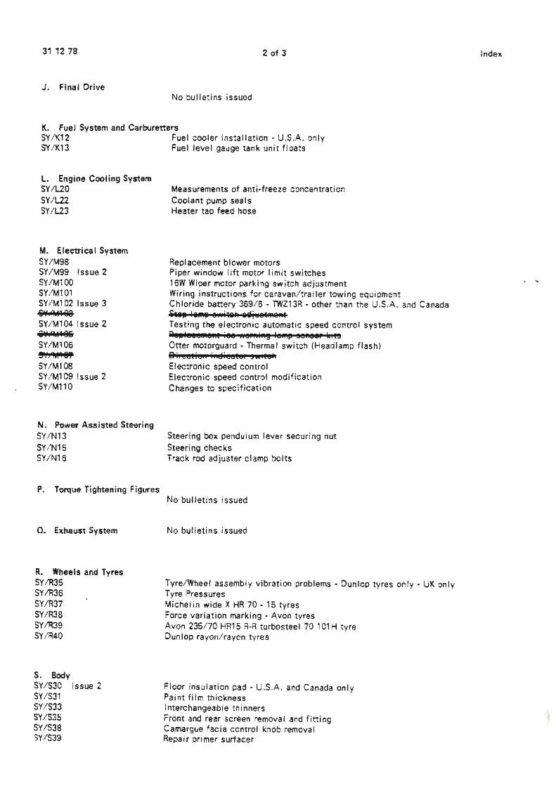
J. Final Drive No bulletins issued
K. Fuel System and Carbtlretters SY/K12 Fuel cooler installation - U.S.A. only SY/K13 Fuel level gauge tank unit floats
L. Engine Cooling System SY/l20 SY/L22 SY/L23
M. Electrical System SY/M98 SY /M99 Issue 2 SY/M100 SY /M101 SY/M102 Issue 3 S¥:<1iH9e SY/M104 Issue 2 SV,''41186 SY/M106 !JV,'fo118Y SY/M108 SY /M1 09 Issue 2 SY/M110
N. Power Assisted Steering SY/N13 SY/N15 SY/N16
P. Torque Tightening Figures
Q. Exhaust System
R. Wheels and Tyres SY/R35 SY/R36 SY/R37 SY/R38 SY/R39 SY/R40
S. Body SY /S30 Issue 2 SY /S31 SY/S33 SY/S3~ SY/S38 5Y/S39
Measurements of anti-freeze concentration Coolant pump seals Heater tap feed hose
Replacement blower motors Piper window lift motor limit switches 16W Wiper motor parking switch adjustment Wiring instructions for caravan/trailer towing equ i oment Chloride battery 369/6 - TWZ13R • other than the U.S.A. and Canada i11,i l&MIJ ewitall 11aj11el"'e"t Testing the electronic automatic speed control system Re15lescn.e::t ice .. ernin~ le"'" eenee, l,its Otter motorguard • Thermal switch (Headlamp flash) 8i:cctie:: i::eiieete: snitel. Electronic speed control Electronic speed control modification Changes to specification
Steering box pendulum lever securing nut Steering checks Track rod adjuster clamp bolts
No bulletins issued
No bulletins issued
Tyre/Wheel assembly vibration problems • Dunlop tyres only • UK only Tyre Pressures Michel in wide X HR 70 • 15 tyres Force variation marking • Avon tyres Avon 235/70 HR15 R-R turbosteel 70 101 H tyre Dunlop rayon/raven tyres
Floor insulation pad - U.S.A. and Canada only Paint fi Im thickness Interchangeable thinners Front and rear screen removal and fitting Camargue facia control knob removal Repair primer surfacer
Index
' "'
31 12 78
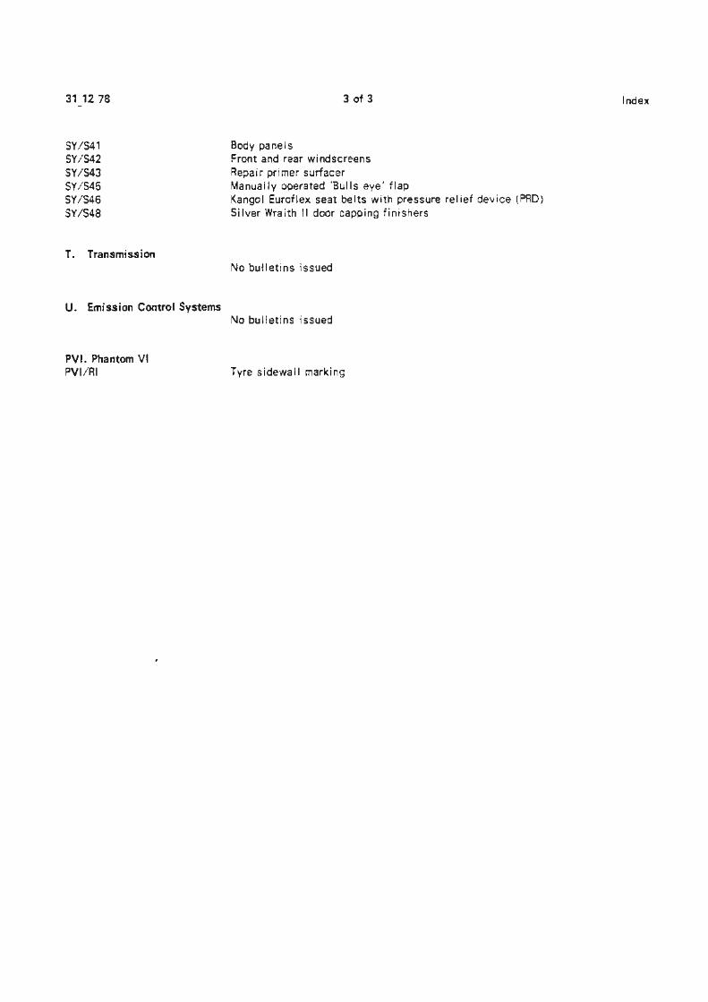
SY/S41 SYiS42 SY/S43 SY/S45 SY/S46 SY/S48
T. Transmission
U. Emission Control Systems
PVI. Phantom VI PVI/RI
3 of 3
Body panels Front and rear windscreens Repair primer surfacer Manually operated 'Bulls eye· flap Kangol Euroflex seat belts with pressure relief device (PAD) Silver Wraith 1 I door capping fi ni she rs
No bulletins issued
No bulletins issued
Tyre sidewall marking
Index
I Service Bulletins
Chapter A
~ General Information
Service Bulletin
I [i))oLLS-11'\0YCE MOTORS
Car Division
TSD4171
Bulletin number SY/A23 · l 3 76 Da te Page 1 of 2
Clrci.:lation list ! ! ! J II II I 11 II II I I I I Catego~
TO ALL DISTRIBUTORS AND RETAILERS
GENERAL PRECAUTIONS INCLUDING TOWING
APPLICABLE TO:
All Rolls-Royce Camargue, Corniche and Silver Shadow cars and all Bentley 'T' series ana·corniche cars.
"' .... "' -,:, :!>ESCRIPTION: :J Jhis Service Bulletin is issued to inform you of the general precautions to adopt in towing and servicing the above-mentioned &rehicles. >,
ri. .i,
!10WING: @) 1 The maximum towing weight must not exceed 1 778 kilogranunes
(35 cwt) •
NOTE The energy absorbing bumpers fitted to cars built for use in North America should not be fitted with any form of towing attachment or used as a load bearing member whilst towing.
2 In order to maintain optimum pressure in both power braking systems of the towed vehicle, it is necessary to run the engine. However, as running the engine at idling speeds for prolonged periods is not recommended it is essential that where cars are towed for a prolonged period a solid tow bar or a suspended towing apparatus is used.
3 The above-mentioned cars can be towed at speeds up to 72 kph (45 mph) for distances of up to 80 kilometers (50 miles).
For faster speeds or longer distances the propeller shaft must be disconnected or the rear wheels raised from the ground.
4 When towing, always ensure that the transmission is in Neutral.
0 ~
1 3 76 2 of 2 SY/A23
5 If any damage to the transmission components is suspected or if the transmission fluid level is low, the propeller shaft must be disconnected or the rear wheels raised from the ground.
SERVICE OPERATIONS
6
7
7a
7b
ECk/MB
Should a service operation necessitate depressurisation of the hydraulic system of an all-power brakes car, sufficient pressure to operate the brakes will be available immediately the engine is cranked.
When any of the previously mentioned vehicles are undergoing a service operation the following procedures should be observed.
Cars Fitted with Four Speed Automatic Gearboxes
When carrying out service work on these cars the 'R' position should be selected on the gear slector lever. Always ensure that the 'R' position has been selected at the gearbox actuator by listening for the audible click. The handbrake should be firmly applied and the gearbox isolator removed.
Cars Fitted with Torque Converter Tra~smission
On these cars the •p• position should be selected on the gear selector lever. Always ensure that the 'P' position has been selected at the gearbox actuator by listening for the audible click, the handbrake (foot operated parking brake if fitted) should be firmly applied and the gearbox isolator removed.
Service Bulletin
Bulletin number SY/A27 Date 17 6 76 PagE::
I I Circulation list 11 II 11 II I 11 11 I Category ·C
ALL DISTRIBUTORS AND RETAILERS
WORKSHOP TOOLS
APPLICABLE TO:
All Rolls-Royce and Bentley motor cars.
INTRODUCTION:
It is apparent that the correct workshop tools are not being used by franchise holders. As a result, damage is being caused to components including service exchange parts. In some instances the damage has been so severe that it has been impossible to rework the components.
DESCRIPTION:
Carrying out any operation on Rolls-Royce and Bentley motor cars is made easier when the correct workshop tools are utilised.
In future, any parts returned under warranty or service exchange which are found to have been damaged as a result of incorrect or careless workshop practice will be made chargeable to the franchise holder.
Hly/MH
I JR{OLLS·
I Mo?~~ Car Division
TSD 4171
l of 1
11 I
~
Service· Bulletin
ID)OLLS· ft\\OYCE MOTORS
car Division
1SD 4171
Bulletin number SY/A28 14 fDa1E6 Page 1 of 11
Circclation list I l 11 II I II II II I II Category c
TO ALL DISTRIBUTORS AND RETAILERS
1976 REGULATIONS SPECIFICATION CHANGES
APPLICABLE TO:
All Rolls-Royce Silver Shadow, Corniche and Camargue cars, and all Bentley T Series and Corniche cars from the following car serial numbers:
Four door saloon - USA and Canada - SRE 25565 and onwards
i Long Wheelbase ~
All other countries - SRX 25625 onwards - USA and Canada - LRE 25596 and onwards
All other countries - LRX 25741 and onwards To be announced £
@) Camargue Corniche Saloon
and Convertible - All countries DRE 25958 and onwards
INTRODUCTION:
This Service Bulletin contains the specification changes arising from the introduction of the 1976 Regulations together with any new service procedures.
DESCRIPTION:
The 1976 Regulation changes contain the following:
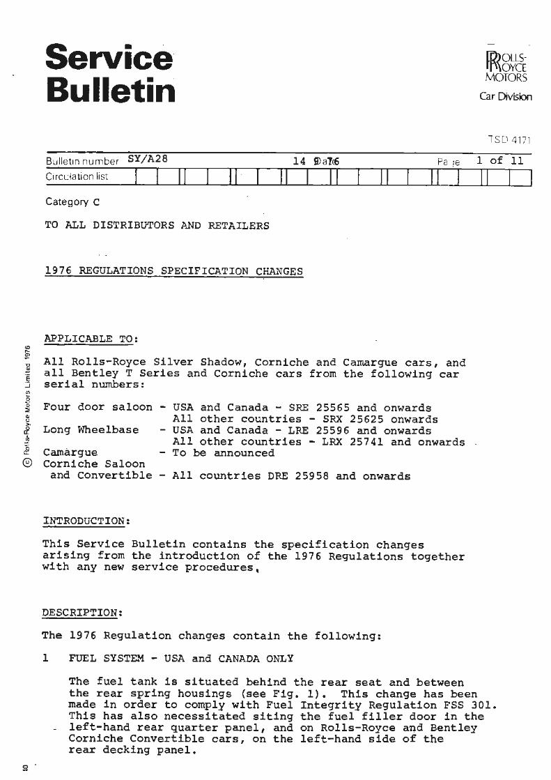
1 FUEL SYSTEM - USA and CANADA ONLY
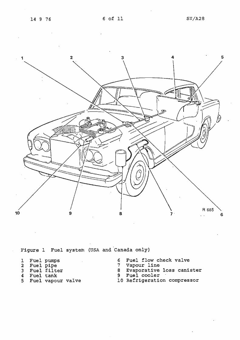
The fuel tank is situated behind the rear seat and between the rear spring housings (see Fig. 1). This change has been made in order to comply with Fuel Integrity Regulation FSS 301. This has also necessitated siting the fuel filler door in the
- left-hand rear quarter panel, and on Rolls-Royce and Bentley Corniche Convertible cars, on the left-hand side of the rear decking panel.
14 9 76 2 of 11 SY/A28
The fuel tank fitted to Rolls-Royce and Bentley Corniche Convertible cars has a larger base area and is shorter in height to allow for the hood stowage.
Both types of fuel tank are retained by metal straps. The fuel capacity of both types of fuel tank is 18.5 Imperial Gallons (22.5 us Gallons).
The fuel filler cap incorporates a combined pressure and vacuum relief valve.
The interior trim of the left-hand rear quarter panel and parcel shelf is changed to accommodate the filler neck (this change does not apply to Rolls-Royce and Bentley Corniche Convertible cars}.
The pipe and hose runs at the rear of the car for evaporative loss and fuel tank venting have changed due to the . repositioning of the fuel tank. Also, a vapour (antirollover) valve is fitted into the evaporative loss line adjacent to the.fuel tank {see Fig. 1).
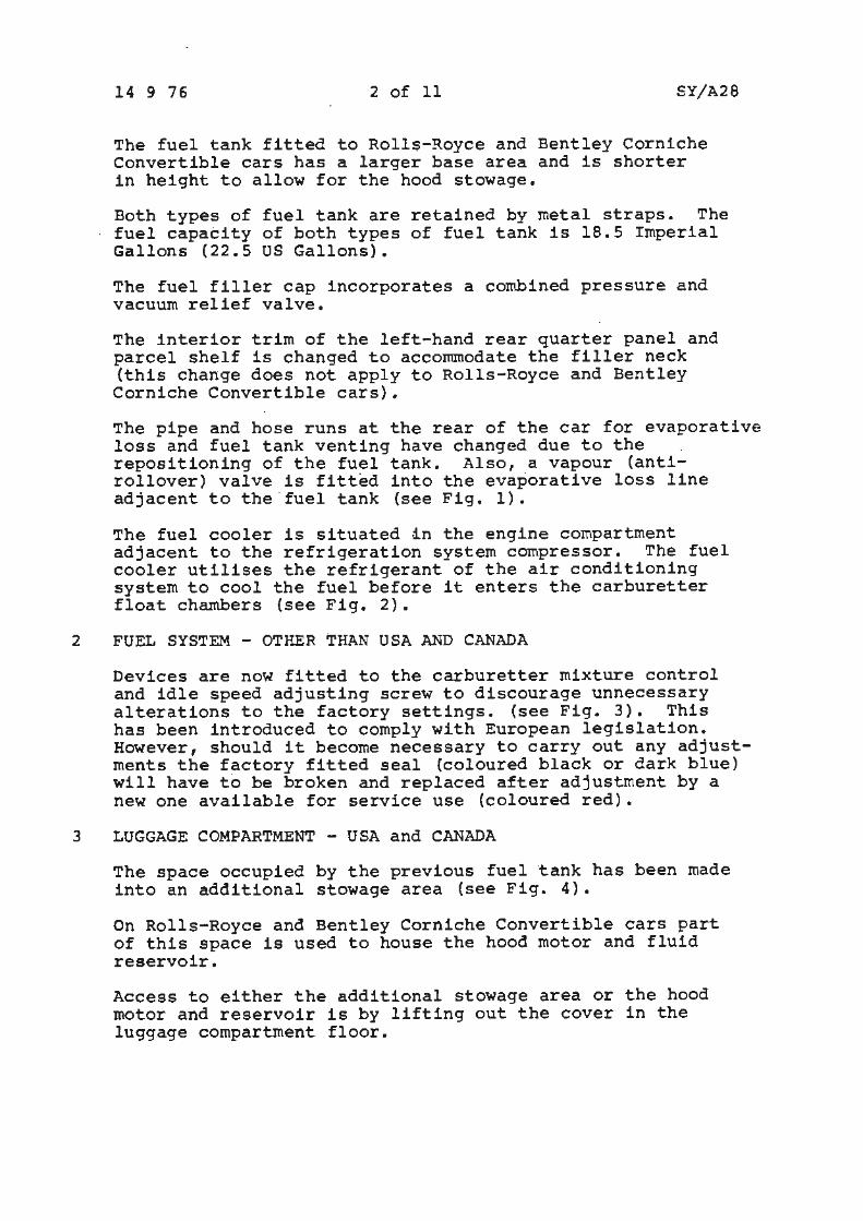
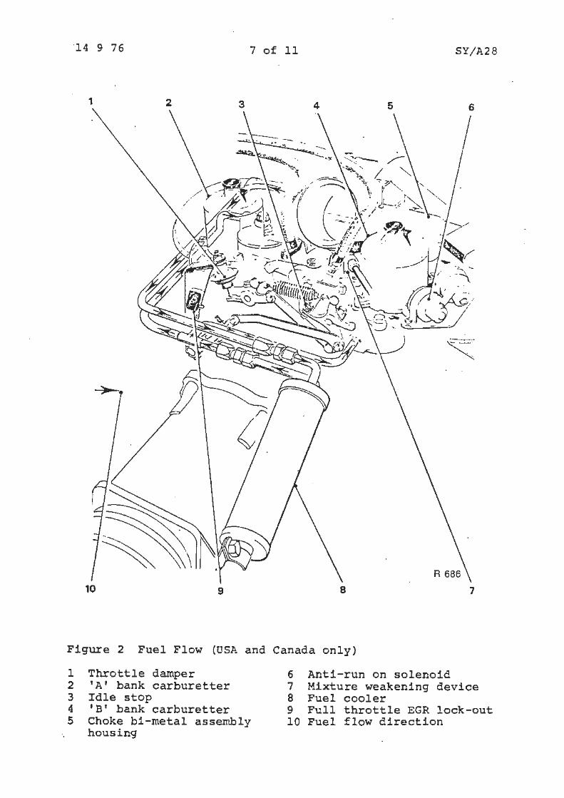
The fuel cooler is situated in the engine compartment adjacent to the refrigeration system compressor. The fuel cooler utilises the refrigerant of the air conditioning system to cool the fuel before it enters the carburetter float chambers (see Fig. 2).
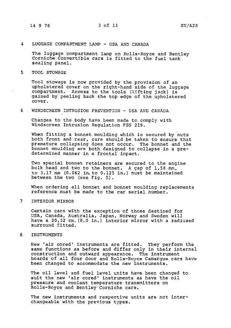
2 FUEL SYSTEM - OTHER THAN USA AND CANADA
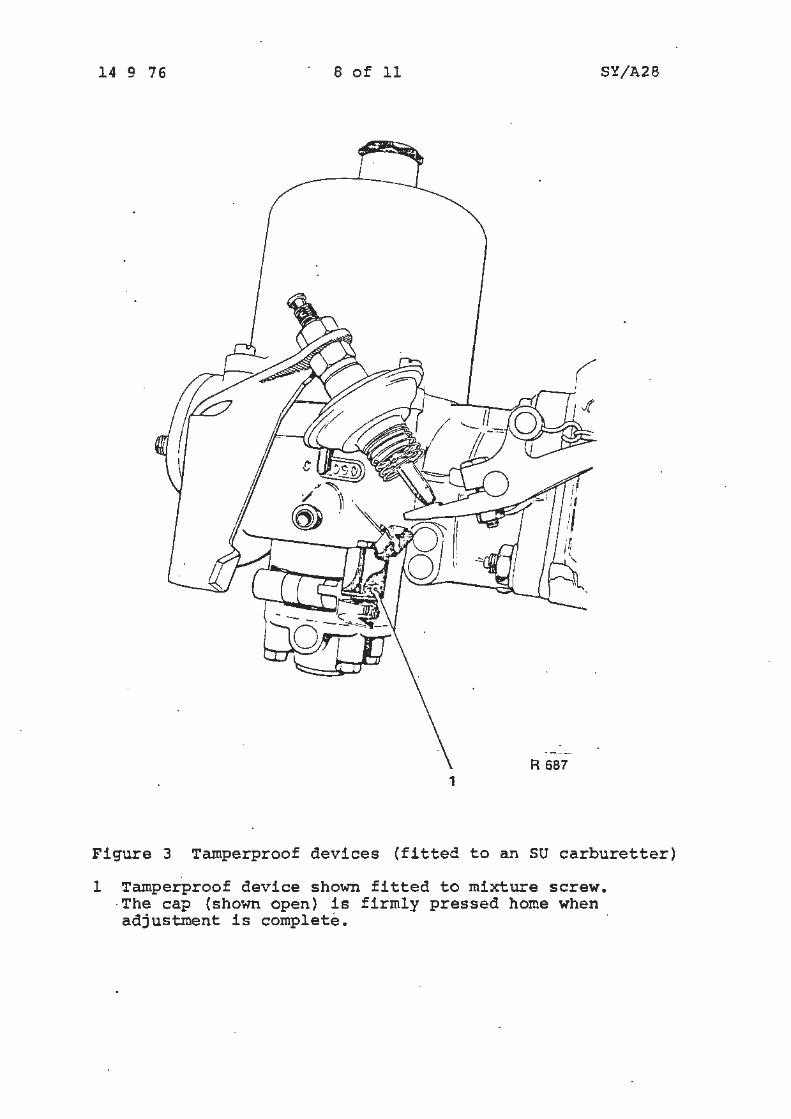
Devices are now fitted to the carburetter mixture control and idle speed adjusting screw to discourage unnecessary alterations to the factory settings. (see Fig. 3). This has been introduced to comply with European legislation. However, should it become necessary to carry out any adjustments the factory fitted seal (coloured black or dark blue) will have to be broken and replaced after adjustment by a new one available for service use (coloured red).
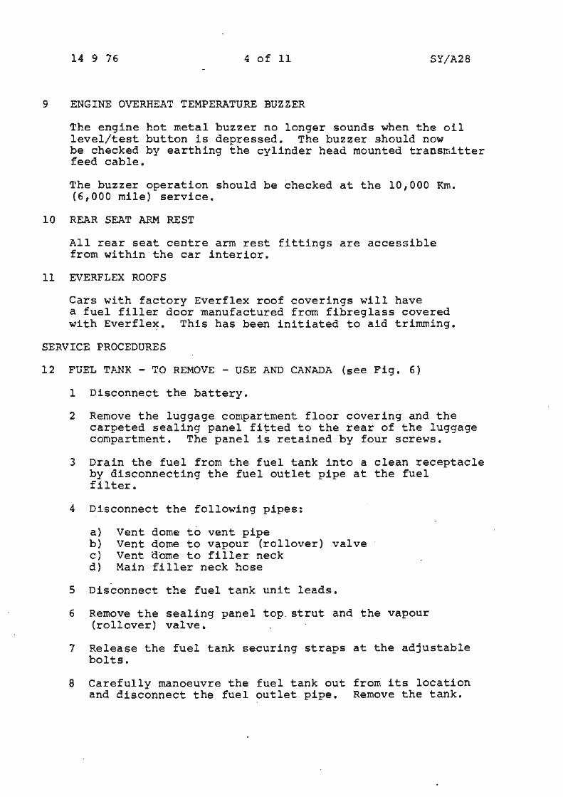
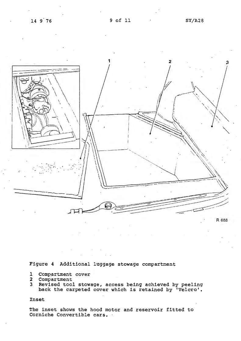
3 LUGGAGE COMPARTMENT - USA and CANADA
The space occupied by the previous fuel ·tank has been made into an additional stowage area (see Fig. 4).
On Rolls-Royce and Bentley Corniche Convertible cars part of this space is used to house the hood motor and fluid reservoir.
Access to either the additional stowage area or the hood motor and reservoir is by lifting out the cover in the luggage compartment floor.
14 9 76 3 of 11 SY/A28
4 LUGGAGE COMPARTMENT LAMP - USA AND CANADA
The luggage compartment lamp on Rolls-Royce and Bentley Corniche Convertible cars is fitted to the fuel tank sealing panel.
5 TOOL STOWAGE
Tool stowage is now provided by the provision of an upholstered cover on the right-hand side of the luggage compartment. Access to the tools (lifting jack) is gained by peeling back -the top edge of .the upholstered cover.
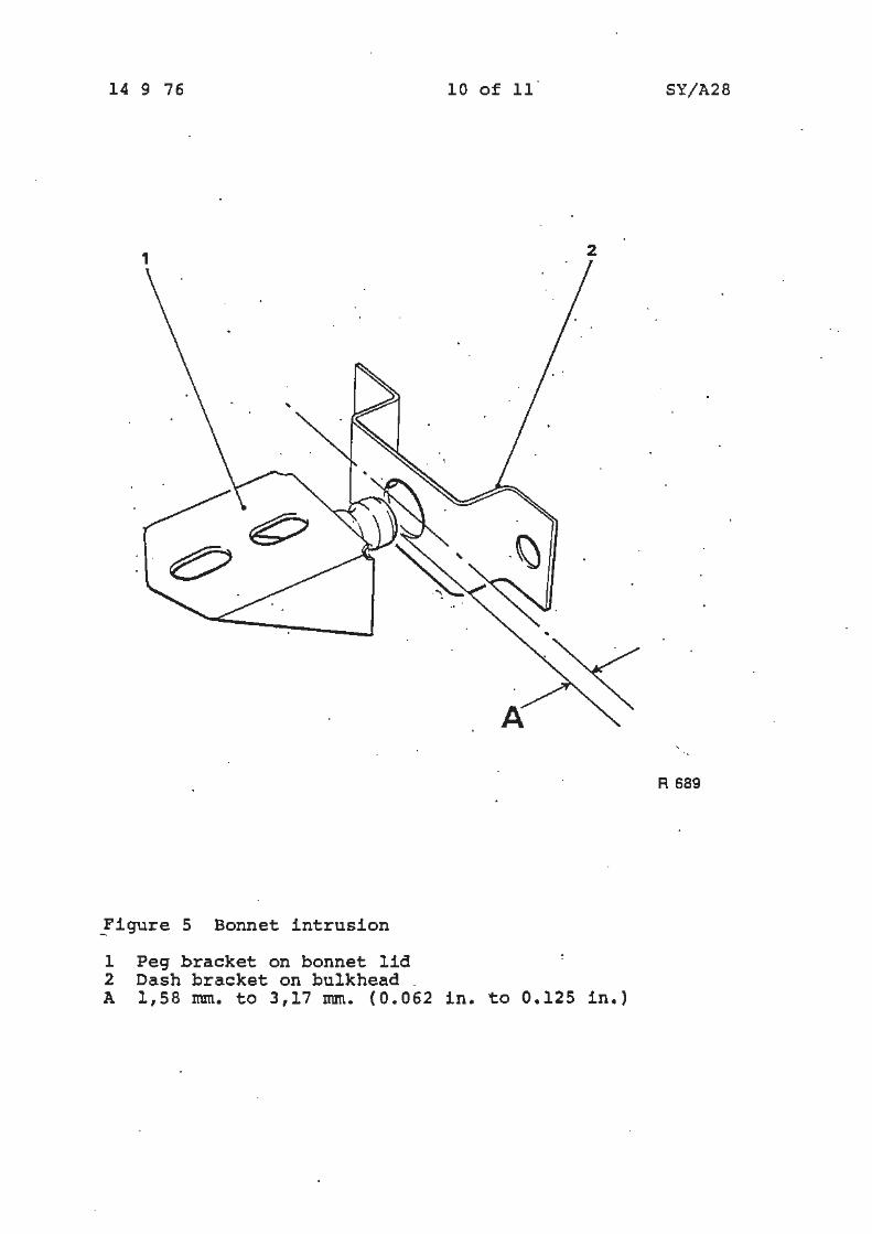
6 WINDSCREEN INTRUSION PREVENTION - USA AND CANADA
Changes to the body have been made to comply with Windscreen Intrusion Regulation FSS 219.
When fitting a bonnet moulding which is secured by nuts both front and rear, care should be taken to ensure that premature collapsing does not occur. The bonnet and the bonnet moulding are both designed to collapse in a predetermined manner in a frontal impact.
Two special bonnet retainers are secured to the engine bulk head and two to the bonnet. A gap of 1,58 mm. to 3.17 mm (0.062 in.to 0.125 in.) must be maintained between the two (see Fig. 5).
When ordering all bonnet and bonnet moulding replacements reference must be made to the car serial number.
7 INTERIOR MIRROR
Certain cars with the exception of those destined for USA, Canada, Australia, Japan, Norway and Sweden will have a 20,32 cm. (8.0 in.) interior mirror with a radiused surround fitted.
8 INSTRUMENTS
New 'air cored' instruments are fitted. They perform the same functions as before and differ only in their internal construction and outward appearance. The instrument boards of all four door and Rolls-Royce Camargue cars have been changed to accommodate the new instruments.
The oil level and fuel level units have been changed to suit the new 'air cored• instruments as have the oil pressure and coolant temperature transmitters on Rolls-Royce and Bentley Corniche cars.
The new instruments and respective units are not interchangeable with the previous types.
14 9 76 4 of 11 SY/A28
9 ENGINE OVERHEAT TEMPERATURE BUZZER
The engine hot metal buzzer no longer sounds when the oil level/test button is depressed. The buzzer should now be checked by earthing the cylinder head mounted transmitter feed cable.
The buzzer operation should be checked at the 10,000 Km. (6,000 mile) service.
10 REAR SEAT ARM REST
All rear seat centre arm rest fittings are accessible from within the car interior.
11 EVERFLEX ROOFS
Cars with factory Everflex roof coverings will have a fuel filler door manufactured from fibreglass covered with Everfle~. This has been initiated to aid trimming.
SERVICE PROCEDURES
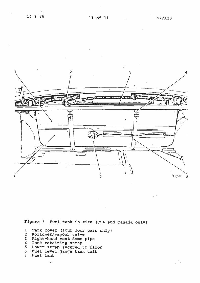
12 FUEL TANK - TO REMOVE - USE AND CANADA (see Fig. 6)
1 Disconnect the battery.
2 Remove the luggage compartment floor covering and the carpeted sealing panel fitted to the rear of the luggage compartment. The panel is retained by four screws.
3 Drain the fuel from the fuel tank into a clean receptacle .by disconnecting the fuel outlet pipe at the fuel filter.
4 Disconnect the following pipes:
a) Vent dome to vent pipe b) Vent dome to vapour (rollover) valve c) Vent dome to filler neck d) Main filler neck hose
5 Disconnect the fuel tank unit leads.
6 Remove the sealing panel top. strut and the vapour {rollover) valve.
7 Release the fuel tank securing straps at the adjustable bolts.
8 Carefully manoeuvre the fuel tank out from its location and disconnect the fuel outlet pipe. Remove the tank.
14 9 76 5 of 11 SY/A28
13 FUEL TANK - TO FIT - USA AND CANADA
To fit the fuel tank reverse the procedure given for its removal.
14 INSTRUMENTS
Fuel gauge - To test (in situ}
1 Disconnect the tank unit feed cable at the tank unit and with the ignition 'on' quickly and momentarily place the · feed cable to a suitable earth and observe that th~ instrument reads 'full'. If it does not, the instrument should be renewed.
Fuel gauge tank unit - To remove
l Proceed with Operations 1, 2 and 3 as described in Feel tank - To remove.
2 Remove the tank unit securing screws.
3 Withdraw the tank unit.
Fuel gauge tank unit - To fit
Fit the tank unit by reversing the removal procedure noting the following:
1 Renew the gasket.
2 Check for fuel leaks.
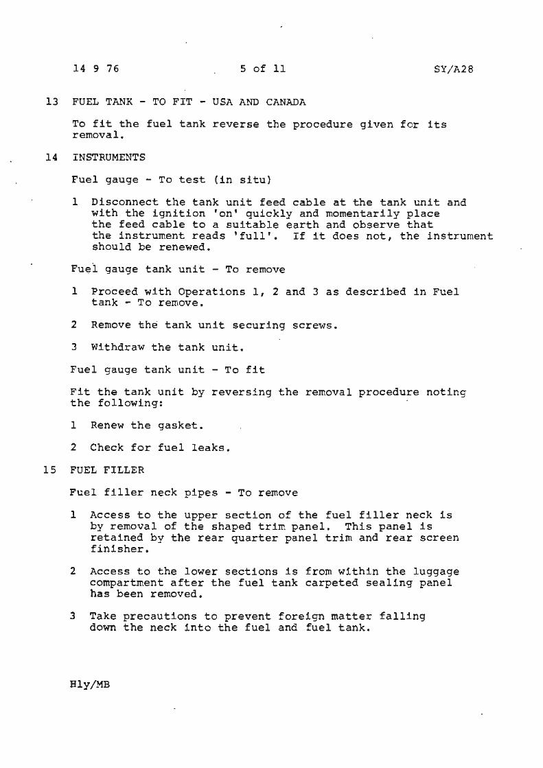
15 FUEL FILLER
Fuel filler neck pipes - To remove
1 Access to the upper section of the fuel filler neck is by removal of the shaped trim panel. This panel is retained by the rear quarter panel trim and rear screen finisher.
2 Access to the lower sections is from within the luggage compartment after the fuel tank carpeted sealing panel has been removed.
3 Take precautions to prevent foreign matter falling down the neck into the fuel and fuel tank.
Hly/MB
14 ·9 76 6 of 11 SY/A28
. 1 2 3 4 5
10
Figur~ 1 Fuel system (USA and Canada only)
l Fuel pumps 6 Fuel flow check valve 2 Fuel pipe 7 Vapour line 3 Fuel filter 8 Evaporative loss canister 4 Fuel t·ank 9 Fuel cooler 5 Fuel vapour valve 10 Refrigeration compressor
·14 9 76 7 of 11 SY/A28
1 2 3 4
10 . 9 8 1
Figure 2 Fuel Flow (USA and Canada only}
1 Throttle damper 2 'A' bank carburetter 3 Idle stop 4 'B' bank carburetter 5 Choke bi-metal assembly
housing
6 Anti-run on solenoid 7 Mixture weakening device 8 Fuel cooler 9 Full throttle EGR lock-out 10 Fuel flow direction
14 9 76 8 of 11 SY/A28
1 .
Figure 3 Tamperproof devices (fitted to an SU carburetter)
1 Tamperproof device shown fitted to mixture screw. -The cap (shown open) is firmly pressed home when adjustment is complete.
14 9 . 76 9 of 11 SY/A28
1 2
I'
\ \\le'::. :,4----(/
\ \ ··~----a; • •
. ·. . . ~- ; • . . ~
Figure 4 Additional luggage stowage compartment
1 Comp_artment cover 2 Compartment 3 Revised tool stowage, access being achieved by peeling
back the carpeted cover which is retained by 'Velcro'.
Inset
The inset shows the hood motor and reservoir fitted to Corniche Convertible cars. ·
R 688
14 9 76
_Figure 5 Bonnet intrusion
l Peg bracket on bonnet lid 2 Dash bracket on bulkhead.
10 of 11
2
..
A ·~
A 1,58 mm. to 3,17 mm. (0.062 in. to 0.125 in.)
. SY/A28
' '•,:
R 689
1
7
14 9 76 11 of 11
2 3
6
Figure 6 Fuel tank in situ (USA and Canada only)
l Tank cover (four door cars only) 2 Rollover/vapour valve 3 Right-hand vent dome pipe 4 Tank retaining strap 5 Lower strap secured to floor 6 Fuel level gauge tank unit 7 Fuel tank
SY/A28
4
A 690 5
0) .... . O> -
Fil ~
Service Bulletins
Chapter B
~ Special Proces.ses
I Service Bulletins
Chapter C
~ Air Conditioning

! e :J ~
Service Bulletin
Bulletin number
Circ~tion list
Category B
ALL DISTRIBUTORS AND RETAILERS
AUTOMATIC AIR CONDITIONING EXPANSION VALVES
APPLICABLE TO:
All Rolls-Royce Camargue cars and all Rolls-Royce and Bentley Corniche cars (fitted with automatic air conditioning system) listed on pages 6 to 8 of this Service Bulletin.
~ INTRODUCTION: ::t ~· i To increase the performance of the automatic air conditioning i system in conditions of high ambient temperatures a new expansion I valve has been fitted to all Camargue and Corniche cars from @) the following car serial numbers.
Rolls-Royce Camargue cars - 24129
Rolls-Royce and Bentley Corniche cars - 24625
The new valve (Part No. UD 21851) is physically identical to the old valve {Part No. UD 15423) but is readily identifiable by a white painted identification spot on the valve body (see Fig. 1).
NOTE l A few isolated cars prior to the above car serial numbers may have the new valve fitted.
NOTE 2 Valve UD 15423 is still used on cars not fitted with automatic air conditioning.
Valve UD 21851 must not be fitted t o any cars which do not have automatic air conditioning.
JR{g~E MOTORS
Car Division
TSD 4171
In order that those cars listed in the rear of this Service Bulletin may be up-dated to the current specification an ad.justment to the expansion valve is required.
0 s
12 10 76 2 of 8 SY/C8
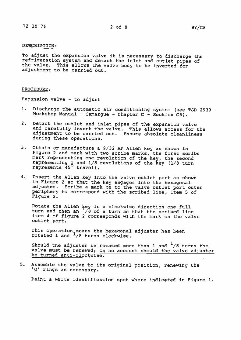
DESCRIPTION:
To adjust the expansion valve it is necessary to discharge the refrigeration system and detach the inlet and outlet pipes of the valve. This allows the valve body to be inverted for adjustment to be carried out.
PROCEDURE:
Expansion valve - to adjust
1. Discharge the automatic air conditioning system (see TSD 2939 -Workshop Manual - Camargue - Chapter C - Section CS).
2. Detach the outlet and inlet pipes of the expansion valve and carefully invert the valve. This allows access for the adjustment to be carried out. Ensure absolute cleanliness during these operations.
3. Obtain or manufacture a 9/32 AF Allen key as shown in Figure 2 and mark with two scribe marks, the first scribe mark representing one revolution of the key, the second representing 6 and 1/8 revolutions of the key {1/8 turn represents 45 travel).
4. Insert the Allen key into the valve outlet port as shown in Figure 2 so that the key engages into the hexagonal adjuster. Scribe a mark on to the valve outlet port outer periphery to correspond with the scribed line, Item 5 of Figure 2.
Rotate the Allen turn and then an item 4 of figure outlet port.
fey in a clockwise direction one full /8 of a turn so that the scribed line
2 corresponds with the mark on the valve
This operation means the hexagonal adjuster has been rotated 1 and 1/8 turns clockwise.
Should the adjuster be rotated more than land 1;a turns the valve must be renewed~ on no account should the valve adjuster be turned anti-clockwise.
5. Assemble the valve to its original position, renewing the 'O' rings as necessary.
Paint a white identification spot where indicated in Figure l.

12 10 76 3 of 8
6. Evacuate, sweep and charge the system as described in TSO 2939 - Workshop Manual - Camargue - Chapter C -Section CS.
TIME ALLOWED
SY/CB
Time allowed for completing all operations including testing -4.25 hours, chargeable to Warranty.
12 10 76 4 of 8
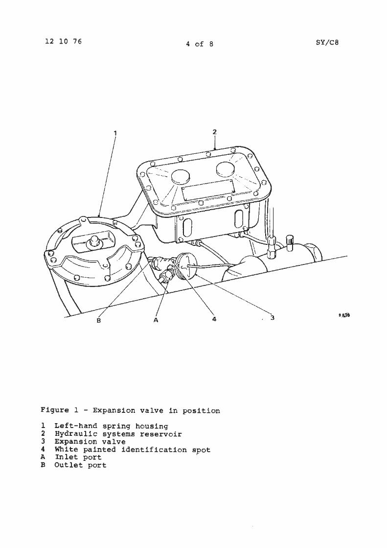
Figure l - Expansion valve in position
l Left-hand spring housing 2 Hydraulic systems reservoir 3 Expansion valve 4 White painted identification spot A Inlet port B Outlet port
SY/C8
12 10 76 5 of 8
1 2 3 4
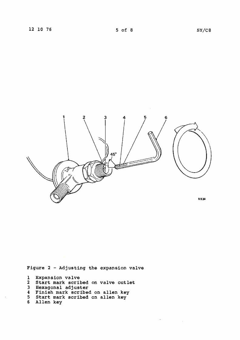
Figure 2 - Adjusting the expansion valve
l Expansion valve 2 Start mark scribed on valve outlet 3 Hexagonal adjuster 4 Finish mark scribed on allen key 5 Start mark scribed on allen key 6 Allen key
SY/CS
5 6
12 10 76 6 of 8 SY/C8
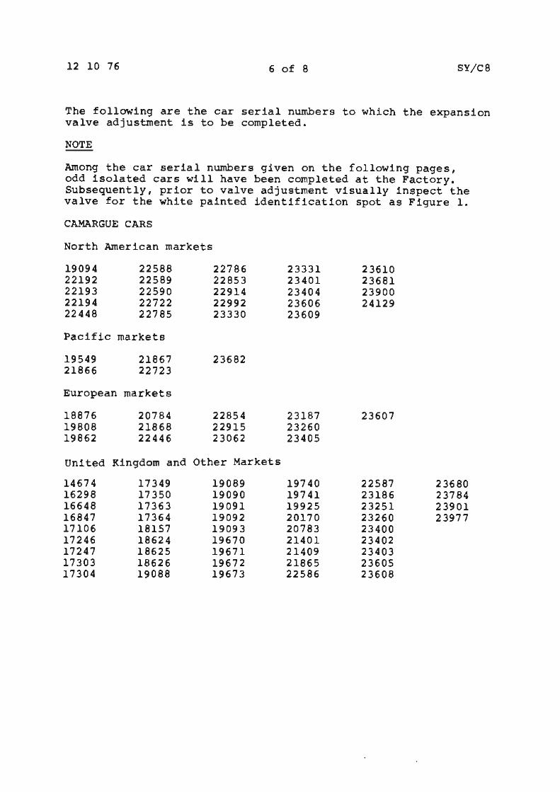
The following are the car serial numbers to which the expansion valve adjustment is to be completed.
NOTE
Among the car serial numbers given on the following pages, odd isolated cars will have been completed at the Factory. Subsequently, prior to valve adjustment visually inspect the valve for the white painted ~dentification spot as Figure 1.
CAMARGUE CARS
North American markets
19094 22588 22786 23331 23610 22192 22589 22853 23401 23681 22193 22590 22914 23404 23900 22194 22722 22992 23606 24129 22448 22785 23330 23609
Pacific markets
19549 21867 23682 21866 22723
European markets
18876 20784 22854 23187 23607 19808 21868 22915 23260 19862 22446 23062 23405
Unit~d Kingdom and Other Markets
14674 17349 19089 19740 22587 23680 16298 17350 19090 19741 23186 ·231a4 16648 17363 19091 19925 23251 23901 16847 17364 19092 20170 23260 23977 17106 18157 19093 20783 23400 17246 18624 19670 21401 23402 17247 18625 19671 21409 23403 17303 18626 19672 21865 23605 17304 19088 19673 22586 23608
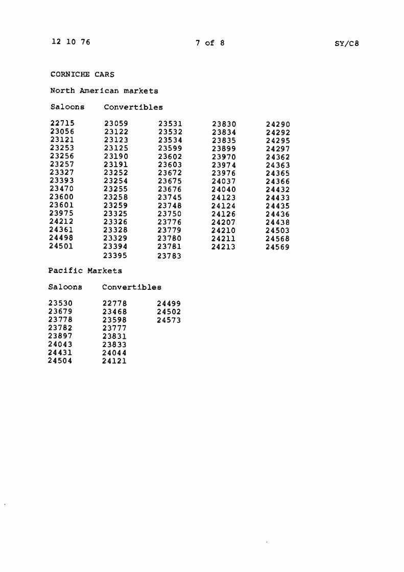
12 10 76 7 of 8 SY/CS
CORNICHE CARS
North American markets
Saloons Convertibles
22715 23059 23531 23830 24290 23056 23122 23532 23834 24292 23121 23123 23534 23835 24295 23253 23125 23599 23899 24297 23256 23190 23602 23970 24362 23257 23191 23603 23974 24363 23327 23252 23672 23976 24365 23393 23254 23675 24037 24366 23470 23255 23676 24040 24432 23600 23258 23745 24123 24433 23601 23259 23748 24124 24435 23975 23325 23750 24126 24436 24212 23326 23776 24207 24438 24361 23328 23779 24210 24503 24498 23329 23780 24211 24568 24501 23394 23781 24213 24569
23395 23783
Pacific Markets
Saloons Convertibles
23530 22778 24499 23679 23468 24502 23778 23598 24573 23782 23777 23897 23831 24043 23833 24431 24044 24504 24121
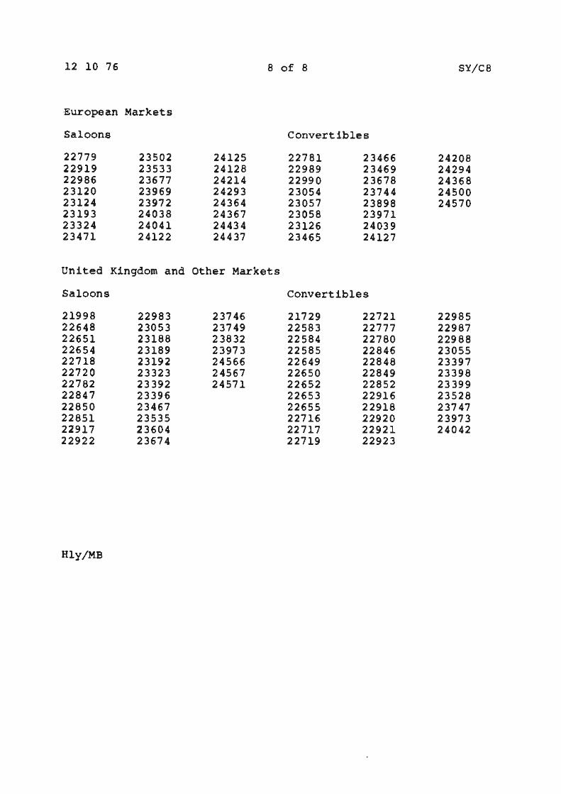
12 10 76 8 of 8 SY/CS
European Markets
Saloons Convertibles
22779 23502 24125 22781 23466 24208 22919 23533 24128 22989 23469 24294 22986 23677 24214 22990 23678 24368 23120 23969 24293 23054 23744 24500 23124 23972 24364 23057 23898 24570 23193 24038 24367 23058 23971 23324 24041 24434 23126 24039 23471 24122 24437 23465 24127
United Kingdom and Other Markets
Saloons Convertibles
21998 22983 23746 21729 22721 22985 22648 23053 23749 22583 22777 22987 22651 23188 23832 22584 22780 22988 22654 23189 23973 22585 22846 23055 22718 23192 24566 22649 22848 23397 22720 23323 24567 22650 22849 23398 22782 23392 24571 22652 22852 23399 22847 23396 22653 22916 23528 22850 23467 22655 22918 23747 22851 23535 22716 22920 23973 22917 23604 22717 22921 24042 22922 23674 22719 22923
Hly/MB
IR{g~E I
MOfORS Service Bulletin Car Division
TSO 4171
Bulletin number SY/clo Date 3 3 77 Pa ge 1 of 1 CircUiation list 11 II 11 I 11 11 Category C
ALL DISTRIBUTORS AND RETAILERS
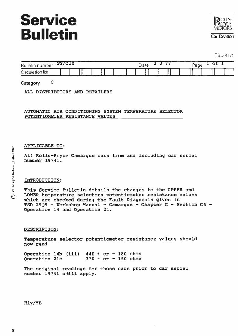
AUTOMATIC AIR CONDITIONING SYSTEM TEMPERATURE SELECTOR POTENTIOME'TER RESISTANCE VALUES
APPLICABLE TO:
11 · I II
All Rolls-Royce Camargue cars from and including car serial number 19741.
INTRODUCTION:
This Service Bulletin details the changes to the UPPER and LOWER temperature selectors potentiometer resistance values which are cheeked during the Fault Diagnosis given in TSD 2939 - Workshop Manual - Camargue - Chapter C - Section C6 -Operation 14 and Operation 21.
DESCRIPTION:
Temperature selector potentiometer resistance values should now read
Operation 14b (iii) 440 + or - 180 ohms Operation 21c 370 + or - 150 ohms
The original readings for those cars prior to car serial number 19741 still apply.
Hly/MB
I Service Bulletins
Chapter D
'491 Lubrication and Maintenance
I l e :J
j
Service Bulletin
Bulletin numbeJ .SY/D22
Circulation list I I 11
Category C
Date
Ir
ALL DISTRIB~~ORS k~D RETAILERS
29 3 77 Page
II 11 II 11 I
PROPELLER SH.AFT l"NIVERSAL JOIN'l' LUBRICATION AND l'I..AINTE:NAt,;CE
APPLICABLE 'I'O:
All Rolls-Royce Silver Shadow, Ccrniche and Carr:argue r.-.otor cars, and all Bentley T series and Corniche motor cars.
DESCF.IPTIO~:
l ! All cars now leaving the factory are fitted with a propeller ! shaft whic..11. :i.as a grease nipple on each of the Hardy Spicer @) universal end joints.
The joints should be lubricated every 40 000 K~. (24,000 niles) using Retinax 'A' grease.
Should it be necessa!:Y to replace a propeller shaft in service e~sure that the Hardy Spi~er universal joint has a grease nipple fitted.
ID>OLLS· I lfT\OYCE MOTORS j
Car Division
1 of l
I I
I Service Bulletins
Chapter E
~ Engine
Service Bulletin
Bulletin number E29
Circulation list I Category c
11
Date 4 2 76
II I II I II
TO ALL DISTRIBUTORS AND RETAILERS ~N JAPAN ONLY
II
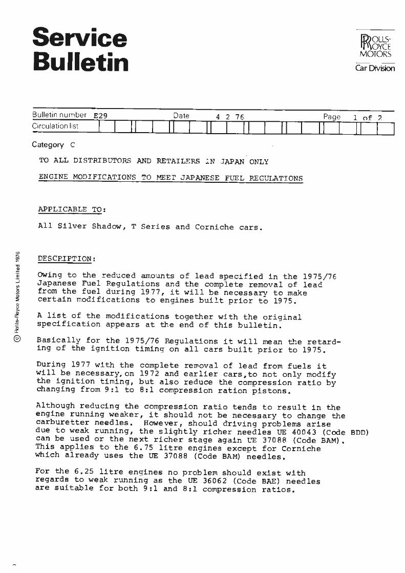
ENGINE MODIFICATIONS TO MEEr JAPANESE FUEL REGULATIONS
APPLICABLE TO:
All Silver Shadow, T Series and Corniche cars.
DESCRIPTION:
Page
II I
OWing to the reduced amounts of lead specified in the 1975/76 Japanese Fuel Regulations and the complete removal of lead from the fuel during 1977, it will be necessary to make certain modifications to engines built prior to 1975.
A list of the modifications together with the original specification appears at the end of this bulletin.
Basically for the 1975/76 P~gulations it will mean the retarding of the ignition timing on all cars built prior to 1975.
During 1977 with the complete rewoval of lead from fuels it will be necessary,on 1972 and earlier cars,to not only modify the ignition timing, but also reduce the compression ratio by changing from 9:1 to 8:1 compression ration pistons.
[r))oLLS- I
ft\\OYCE MOTORS I
Car Division
1 of?.
11 I
Although reducing the compression ratio tends to result in the engine running weaker, it should not be necessary to change the carburetter needles. However, should driving problems arise due to weak running, the slightly richer needles UE 40043 (Code BDD) can be used or the next richer stage again ~"E 37088 {Code BAM). This applies to the 6.75 litre engines except for Corniche which already uses the UE 37088 (Code BAM) needles.
For the 6.25 litre engines no problem should exist with regards to weak running as the UE 36062 {Code BAE) needles are suitable for both 9:1 and 8:1 compression ratios.
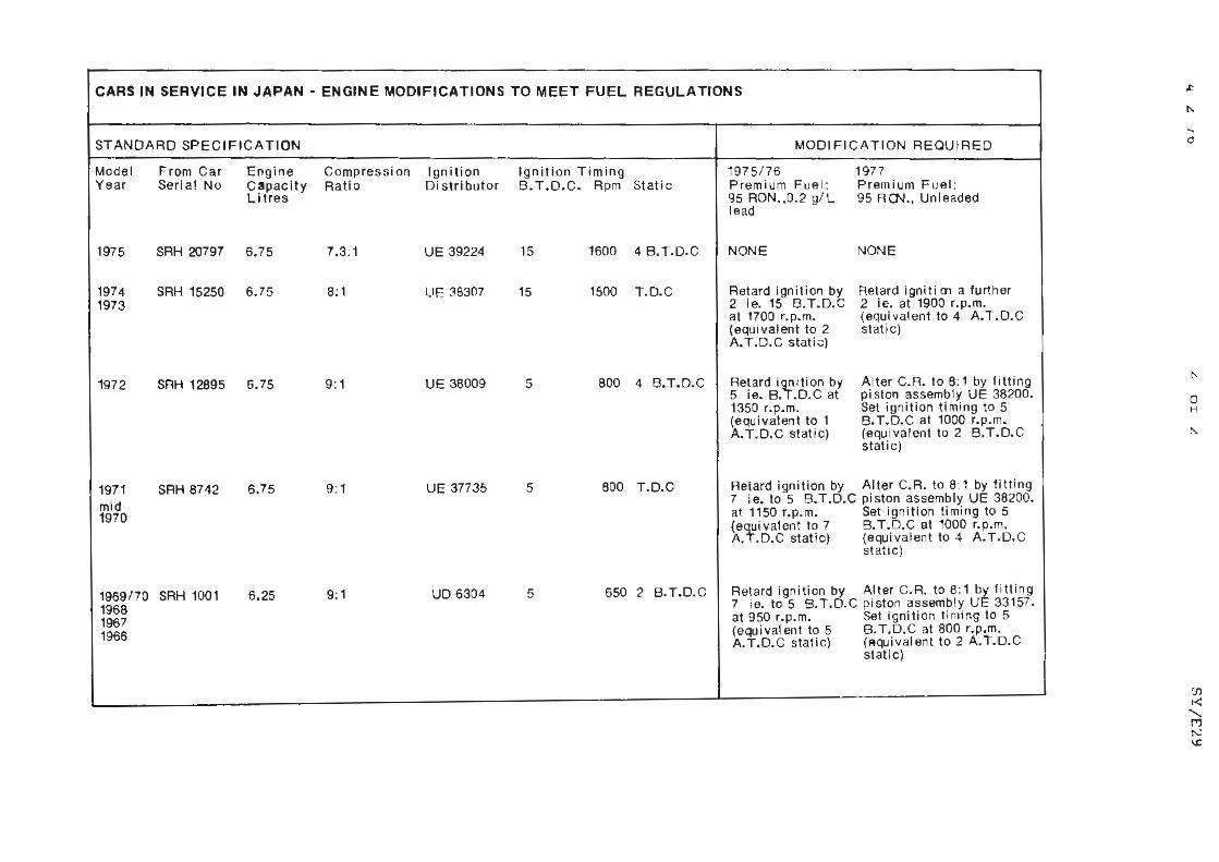
CARS IN SERVICE IN JAPAN - ENGINE MODIFICATIONS TO MEET FUEL REGULATIONS
STANDARD SPECIFICATION MODIFICATION REQUI RED
Model From Car Engine Compression Ignition Ignition Timing 1975/76 1977 Year Serial No Capacity Ratio Distributor B.T.O.C. Rpm Static Premium Fuel: Premium Fuel:
Litres 95 RON. ,0. 2 g/ L 95 RO..J., Unleaded lead
1975 SRH 20797 6.75 7.3: 1 UE 39224 15 1600 4 B.T. O.C NONE NONE
1974 SRH 15250 6.75 8: 1 Uf: 38307 15 1500 T.D.C Retard ignition by Retard igniti 01 a further 1973 2 ie. 15 B.T.D.C 2 ie. at 1900 r.p.m.
at 1700 r.p.m. (equivalent to 4 A.T.D.C (equivalent to 2 static) A.T .D.C stati ;:;)
1972 SRH 12895 6.75 9: 1 UE 38009 5 800 4 8.T.O.C Retard i~ition by Al ter C.R. to 8: 1 by fitting 5 ie. 8 •• D.C at piston assembly UE 38200. 1350 r.p.m. Set ignition timing to 5 (equivalent to 1 B. T.O.C at 1000 r.p.m. A. T.O.C static) (equivalent to 2 8 .T.D.C
static)
1971 SRH 8742 6.75 9:1 UE 37735 5 800 T.O.C Reiard ignition by Alter C.R. to 8: 1 by fittin g
mid 7 ie. to 5 B.T.O.C piston assembly UE 38200.
1970 a~ 1150 r.p.m. Set ignition timing to 5 (efivalent to 7 B. T.D.C at 1000 r.p.m. A . • D.C static) (equival en t to 4 A. T.D.C
static)
1969/70 SRH 1001 6.25 9: 1 uo 6304 5 650 2 B.T.D.C Retard ignition by Alter C.R. to 8:1 by fitting
1968 7 ie. to 5 8.T.D.C pi ston assembly UE 33157.
1967 at 950 r.p. m. Set ignition timing to 5
1966 (equivalent to 5 8. T.D.C at 800 r.p.m. A. T.D.C static) (Aquival en t to 2 A. T.D.C
static)
0
0 H
<&J ,.._ ~ ',:)
~ E :,j fl)
0 0 ~ IP 0 >,
cf J.,
& ©
Service Bulletin
Bulletin number SY/E31 Da te 17 6 76 Pa ge
C1rcu/.at1on 11st II 11 II 11 11 II I Category c
ALL DISTRIBUTORS AND RETAILERS
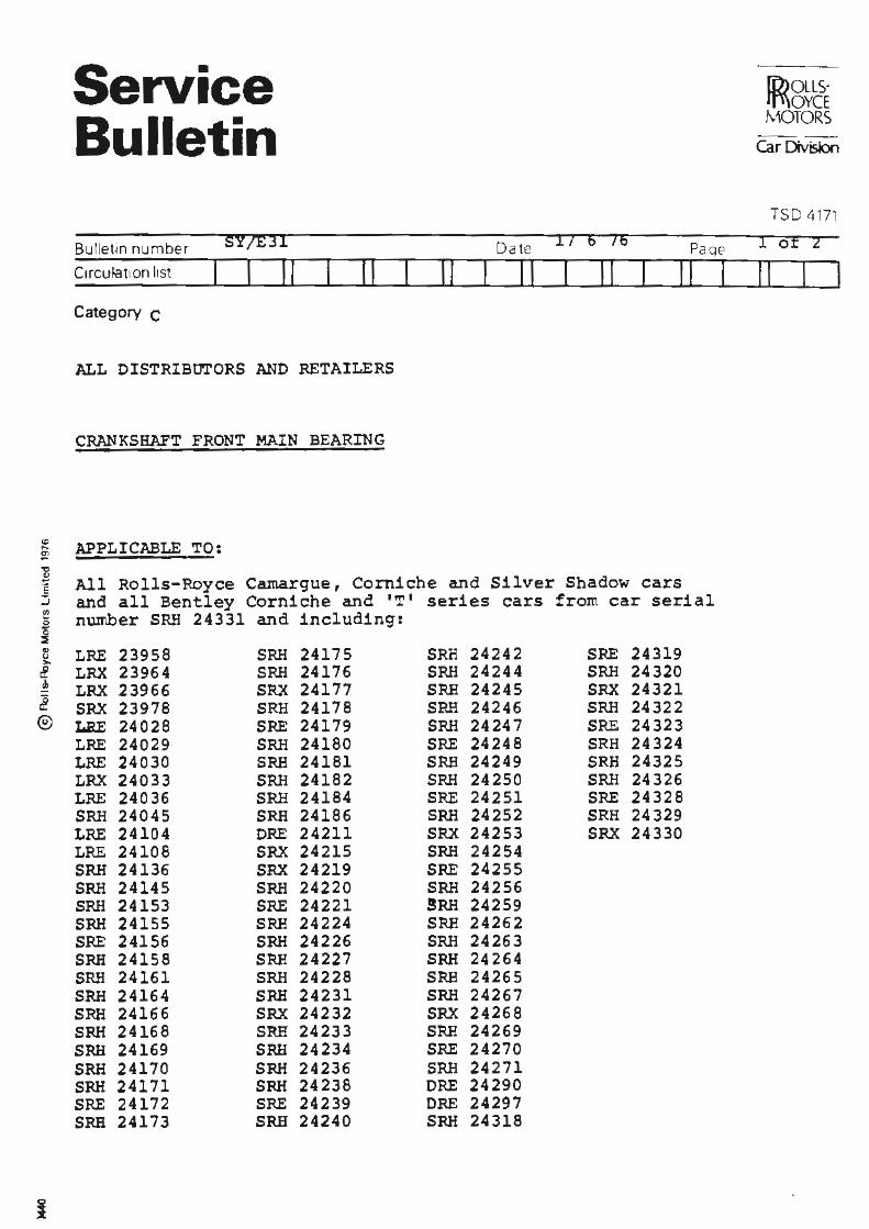
CRANKSHAFT FRONT MAIN BEARING
APPLICABLE TO:
All Rolls-Royce Camargue, Corniche and Silver Shadow cars and all Bentley Corniche and 'T' series cars from car serial number SRH 24331 and including:
LRE 23958 SRH 24175 SRH 24242 SRE 24319 LRX 23964 SRH 24176 SRH 24244 SRH 24320 LRX 23966 SRX 24177 SRH 24245 SRX 24321 SRX 23978 SRH 24178 SP.H 24246 SRH 24322 I.BE 24028 SRE 24179 SRH 24247 SRE 24323 LRE 24029 SRH 24180 SRE 24248 SRH 24324 LRE 24030 SRH 24181 SRH 24249 SRH 24325 LRX 24033 SRH 24182 SRH 24250 SRH 24326 LRE 24036 SRH 24184 SRE 24251 SRE 24328 SRH 24045 SRH 24186 SRH 24252 SRH 24329 LRE 24104 DRE 24211 SRX 24253 SRX 24330 LRE 24108 SRX 24215 SRH 24254 SRH 24136 SRX 24219 SRE 24255 SRH 24145 SRH 24220 SRH 24256 SRH 24153 SRE 24221 !RH 24259 SRH 24155 SRH 24224 SRH 24262 SRE 24156 SRH 24226 SRH 24263 SRH 24158 SRH 24227 SRH 24264 SRH 24161 SRH 24228 SRH 24265 SRH 24164 SRH 24231 SRH 24267 SRH 24166 SRX 24232 SRX 24268 SRH 24168 SRH 24233 SRH 24269 SRH 24169 SRH 24234 SRE 24270 SRH 24170 SRH 24236 SRH 24271 SRH 24171 SRH 24238 DRE 24290 SRE 24172 SRE 24239 DRE 24297 SRH 24173 SRH 24240 SRH 24318
lD>OLLS· ' rf\\OYCE MOTORS
Car Division
TSD 4171
1 of 2
11
17 6 76 2 of 2 SY/E31
INTRODUCTION:
A new front main bearing is fitted to the above cars. The bearing has a greater load bearing area but the bearing material itself remains unchanged.
The increased area has been achieved by using a bearing without a centre groove. The overall dimensions of the bearing remain unchanged.
DESCRIPTION:
In order to avoid oil starvation it is essential that the new bearing shells are fitted only to the above cars and only to the front main bearing journals. To reduce the possibility of these shells being fitted to other journals, the locating tang has been slightly offset on the front main bearing shells, the front main bearing housing and the main bearing cap.
Due to these dimensional changes it will not be possible to retrospectively fit these bearings to earlier cars and reference should be made when ordering parts to Spares Information Sheet Nu:rnber 4 A 72.
Hly/DC
0 ..
Service Bulletin
Bulletin number SY/E33 Date 4 2 76 Page
Circu lation list I 11 11 I 11 11 11 11 I Category C
TO ALL DISTRIBUTORS AN.o -Ri:TAILERS
ENGINE OIL FILTERS
APPLICABLE TO:
All Silver Shadow, T Series, Corniche and Carnargue cars.
DESCRIPTION:
It is known that engine oil filter elements which do not conform with Rolls-Royce Motors recommendations are avai lable and have been fitted.
Tests recently completed confirm that the restriction to oil flow through these oil filters is sufficiently high to risk lubrication breakdown under certain conditions.
It is essential that the only filter element used is the British Filters element which is available from Rolls-Royce Motors under part number RH 2543.
The use of any other filter element may invalidate the engine warranty.
[i))QLLS· lf\\OYCE MOTORS
Car Division
1 of 1
11 I
Service Bulletin
Bulletin number
Circulation list
Category c
ALL DISTRIBUTORS .AND RETAILERS
AIR PUMP - EXHAUST EMISSION CONTROL
APPLICABLE TO:
All Rolls-Royce Camargue, Corniche and Silver Shadow cars and all Bentley Corniche and 'T' series cars from car serial nwnber SRA 14521 and including:
8 LRA 14095 l CRA 14278 ~ LRA 14332 ~ LRA 14333 8 LRA 14384
LRA 14443 LRA 14444 LRA 14445 LRA 14446 SRA 14453 SRA 14456 SRA 14464 SRA 14467 SRA 14475 SRA 14478 SRA 14487 SRA 14490 SRA 14510 SRA 14513
Q
LRA 14386 LRA 14388 LRA 14389 LRA 14391 SRA 14409 SRA 14415 SRA 14420 SRA 14424 SRA 14430
INTRODUCTION:
The three vane type air pump has been replaced by a two vane type. The new pump has different mountings and hose connections. The two vane pump will be supplied for all replacement purposes.
ID>ousrt\\ovcE MOTORS
Car Division
TSD 4171
17 6 76 2 of 2 SY/E34
DESCRn>TI'ON:
When replacing a three vane pump with a two vane pump the following procedure should be followed.
Remove the existing air pump.
Also remove,hose - air pump to 4-way connection mounting bracket, bridge and adjusting strut to air pump. Pump intake silencer, hoses and brackets. Bobbin - induction manifold to coolant pump. Elbow - bypass coolant pump.
Retain bolts and washers - all other parts to be discarded.
Remove fan and alternator drive belt as described in Workshop Manual Chapter Lin order to remove the air pump drive belt. Discard the air pump drive belt.
All new parts required to carry out the change frorn a three vane to a two vane air pump, except the drive belt (Part No VE 36363}, are supplied in Kit No RH 2565. No intake silencer is needed with the new pump.
Assemble using new parts as follor,,..rs:
Fit the bobbin and elbow into the manifold and coolant pump.
Fit the mounting bracket, mounting bridge and adjusting strut loosely onto the engine.
Fit the pulley onto the air pump using the 2 set screws supplied.
Fit the air pump onto the mounting units (using 2 washers and bolt supplied for the adjusting strut).
Fit the new drive belt, tighten the mounting units and tension belt as described in Chapter L of the Workshop Manual.
Fit the hose from the air pump to the 4-way connector.
Refit the alternator drive belt and fan and adjust the belt to the correct tension as described in Chapter L of the Workshop Manual.
Q
Service Bulletin
Bulletin number
Circulation list
Category C
NON-AV.\ILABILITY OF 100 (Rcrn OCr.!'A!'iE FU.SL
APPLICA?LB TO:
Al l Rolls-Royce a~ d Bentley Cars .
IN';:'RODUC'IIO:~
ID)OLLS· rf-\\OYCE .'v~OTORS
Car Division
TSD t.171
1 00 (RON) Octane Fuel (know~ in the Unite 6 Kingdo~ as Five Star r~cl ) is beccr'.;ing ir.c reasir.gly c:i ff icult to obtc.i !l. 97 (RO::;) Ocl:ar~o Fue J. is avail able in most territories and cur~ e nt ~~g ines with 8 :1 c ompression ratios have been ~esigned t n c op0 with these lrn1er octane fue ls. This bullet i n has been is ;:;ue d to d-2sc~ :i.be the proced-.i~ c. ',:~,_ j_c !.~ shoul~ be adopted to enabl2 e a rl i2r ensincs to run sat is f ~c tcri l y ~~ these l ower octane fuels.
DESC::.:ZlP'l'IQ!;
9: 1 compression r atio e ngines wi l l norrr,c.l ly r t~n ~a-::. :~ sfacto rily C !'..
97 to 99 Oc tane Fuel an~ the ignition timing on th2 above cars should there fore b e set to the stand~=e setting.
There is the possibility, depEn d~nt ~pon operati ng ~onditi ons a~~ the general condition 0£ the eng ine, that detonation may cccur. Detonation i s ?. condi tio :'."l s:,,,,hich manifests itself as a "ti;1.kl ir_-3" noise from the engine un~er c onditions of heavy load at meduin en; l.ne speeds. In the event o f a corr-.pl a.int of c"?etonc1t :.. c n, the f ollc-"111~.;procecure should b e adopted .
PROCEDURE
1. Set the ignition timing to the standard setting. 2. Determine whether or not detonation i s evident, by acceler c~ting
the car up a steep incline in top gear with9ut eligaging kickaown. Detonation will usua lly occur at e ngine speeds between 2,000 and 3, 00 0 rpm.

15 12 78 2 of 2 SY/E35
3.
4. s. 6.
If detonation is present, retard the ignition 7°. Check ~o ensure that this has eliminated the detonation. Retarding the ignition may result in a deterioration of performance. Carry out Operations 4 and 5 ;o obtain the best performance. Advance the ignition timing 2 and repeat Operation
02.
Continue to advance the ignition in increments of 2 repeating Operation 2 until det8nation occurs. Retard the ignition 2.
Hly/DC
Service Bulletins
Chapter F
Propeller Shaft
and Universal Joints
Service Bulletins
Chapter G . Hydraulic Systems
Service Bulletin
Categoryc " II
TO ALL DISTRIBUTORS AND RETAILERS
FLEXIBLE BRAKE HOSES
APPLICABLE TO:
Pa ge
II II I
All Rolls-Royce Silver Shadow, Corniche and Camargue cars and all Bentley T series and Corniche cars from the following car serial nwnbers.
:e
I (i.))ous. 1
lf'\OYCE 1 MOTORS
c.ar Division
TS04171
1 of 1
II I
%ilver Shadow saloon ,:, ~
iong Wheelbase ff,
5
SRE 22788, 22794, 22805, 22811 and onwards
LRE 22772, 22773, 22774, 22776, 22832, 22833, 22835, 22845, 22900, 22903 and
~ t ce=orniche i! S:amargue ©
DESCRIPTION:
onwards
CRE 23056 and onwards, DRE 23059 and onwards
JRE 22192 and onwards
Your attention is drawn to Spares Information Sheet 4.K.12 Issue 2 describing new flexible brake hoses and their respective part numbers.
The new hoses are identifiable by two longitudinal moulded off-white stripes in the surface herringbone finish together with a marker band with the manufacturers 'insignia'. Also the date of manufacture is let into the hose surface (eg 12/25/75).
The new hoses are fitted as original equipment to the above cars to comply with the appropriate FMVSS regulations. In the unlikely event of any of these hoses having to be renewed prior to the car being handed over to the first owner, then the replacement must be of the same type as the one removed.
The stock displaced(previous type)hoses may be used for replacements on all cars until such time as they are used up.
ECk/MB
i '1:1 ~ e
Service Bulletin
Bulletin number SY/G64 Circdation list I I II Category C
II
ALL DISTRIBUTORS AND RETAILERS
GENERAL PRECAUTIONS
APPLICABLE TO:
" Date
II 20 8 76
II Page
II I
All Rolls-Royce Silver Shadow, Corniche and Carnargue cars and all Bentley 'T' series and Corniche cars.
I lD>OLLS- I 11'\0YCE 1
I MOTORS I Car Division
TSD 4171
1 of~
II
~ INTRODUCTION: £ ! All cars from the following car serial nwrJ,ers are fitted with J- all power brakes. J,
£ ©
4 Door Saloon SRD 22118 (including SRH 21515 and SRD 21693).
Long Wheelbase LRD 22073.
Corniche Convertible DRH 22583 (Right-hand drive). DRX 22781 (Left-hand drive).
Corniche Saloon CRH 22648 (Right-hand drive). CRX 22919 (Left-hand drive).
Camargue JRR 21866.
The pressure for the braking system is provided by the two hydraulic accumulators, which are charged by the engine operated hydraulic pumps.
Braking can only be obtained for a limited number of brake pedal applications if the engine is not running. Continued operation of the pedal will eventually exhaust the accumulator pressures.
~nen manoeuvring a motor car fitted with all power brakes the engine should always be running. If for any reason this is not possible then certain precautions rnust be observed.
It is advisable to follow the same precautions when manoeuvring all cars.
20 8 76 2 of 2 SY/G6~
DESCRIPTION:
l TOWING
When towing or recovering a Rolls-Royce Silver Shadow, Corniche, Camargue, or Bentley T Series or Corniche, even for short distances, a solid tow bar must be used or the car must be low loaded. Towing can only be used for distances up to 80 kilometres (50 miles) and maximum towing speeds of 72 k.p.h. For greater distances the propeller shaft must be disconnected or the vehicle must be transported.
2 DRIVING
Never coasta motor car in 'Neutral' whether the engine is running or not.
Never free-wheel downhill with the engine not running.
When starting the engine of a motor car parked on an incline ensure that the handbrake is firmly applied and leave the gearlever in the 'Park' position. Start the engine before operating either of these two controls. On earlier cars fitted with the four speed trans~ission ensure that the handbrake is firmly applied before moving the gearlever to 'N' to start the engine.
3 MP.N OEUVRIN G
Hly
1 The motor ear must always be winched off a transporter.
2 Do not push the vehicle down any steep inclines unless the engine is running.
3 If a vehicle is being manoeuvred without the engine running, the footbrake will not stop the motor car, if the hydraulic systems are exhausted,

I Service Bulletins
Chapter H
~ Sub .. frames and Suspension
I Service Bulletins
Chapter.J
~ Final Drive
Service Bulletins
Chapter K Fuel System
and Carburetters

Service Bulletin
Bullet.in number
Circu~tion 11st
Category c
11 II
ALL DISTRIBUTORS AND RETAILERS IN THE USA ONLY
FUEL COOLER INSTALLATION
APPLICABLE TO:
Date
II II 23 7 76 Page
I 11 II I
ID>OLLSIf\\OYCE MOTORS
Car Division
TSO 4171
1 of 14
11 I
'O ~ E ::;
All Rolls-Royce Corniche and Silver Shadow cars and all Bentley Corniche and 'T' series cars built to the 1975 and 1976 emission control regulations ie. carR bearing the suffix 'D' or 'E' in
~ .9 ~ ~
the car serial number.
[ INTRODUCTION: ~ £ It has been found that fuel evaporation may occur in high ® ambient temperatures, at high altitudes or in conditions of
slow city driving. Also, this condition may occur when requiring large throttle openings with relatively low vehicle speeds eg. long steep inclines.
These conditions can result in poor engine performance similar to that caused by fuel starvation.
Once vapourisation has occurred it is necessary to allow the car to cool for some considerable time before normal running can again be achieved.
The fitting of a fuel cooler in conjunction with other alterations to the fuel system wi.11 overcome fuel vapourisation.
DESCRIPTION:
The fuel cooler utilises the refrigeration gas as a cooling agent and is incorporated in a new refrigeration return pipe. This pipe replaces the original.
The fuel cooler is mounted on the left-hand side of the refrigeration compressor.
23 7 7( 2 of 14 S~{/Kl2
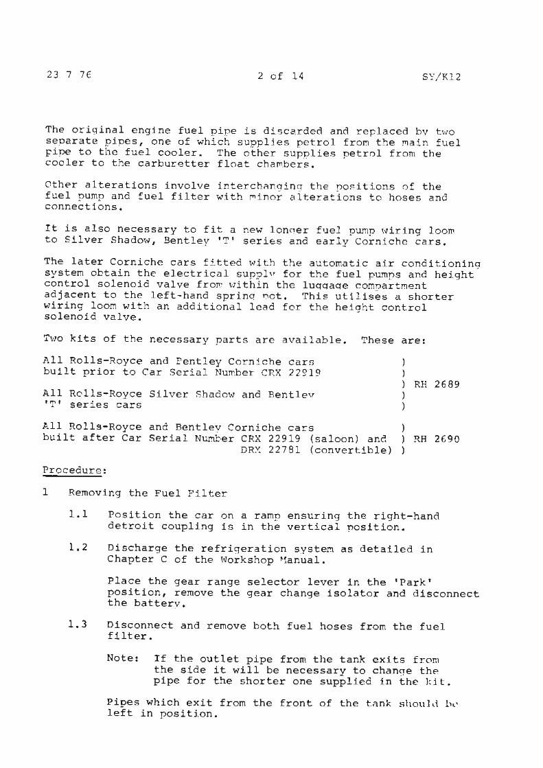
The original engine fuel pipe is discarded and replaced by two seoarate pioes, one of which supplies petrol fro~ the Main fuel FiPe to the fuel cooler. The other supplies petrol from the cooler to the carburetter float cha~bers.
Other alterations involve interch~nging the po~itions of the fuel pump and fuel filter with ~inor alterations to hoses and connections.
It is also necessary to fit a new lonqer fuel pump wiring loom to Silver Shadow, Bentley 'T' series and early Corniche cars.
The later Corniche cars fitted with the automatic air conditioning system obtain the electrical suppl" for the fuel pumps and height control solenoid valve fro~ within the luqqaqe comnartment adjacent to the left-hand sprinq Dot. This utilises a shorter wiring loom with an additional lead for the height control solenoid valve.
Two kits of the necessary parts are available. These are:
All Rolls-Royce and Pentley Corniche car:. built prior to Car Serial Number CRX 22?19
. ) ) ) RH 2689
All Rolls-Royce Silver Shadow and Rentlev 'T' series cars
) )
All Rolls-Royce and Bentley Corniche cars ) built after Car Serial Number CRX 22919 (saloon) anc! ) RH 2690
DRX 22781 (convertible) )
Procedure:
1 Removing the Fuel Filter
1.1 Position the car on a ramp ensuring the right-hand detroit coupling is in the vertical position.
1.2 Discharge the refrigeration system as detailed in Chapter C of the Workshop ~1anual.
Place the gear range selector lever in the 'Park' position, remove the gear change isolator and disconnect the battery.
1.3 Disconnect and remove both fuel hoses from the fuel filter.
Note: If the outlet pipe from the tank exits from the side it will be necessary to chan~e the pipe for the shorter one supplied in the kit.
Pipes which exit from the front of the tonk should bl' left in position.
23 7 76 3 of 14 SY/I<12
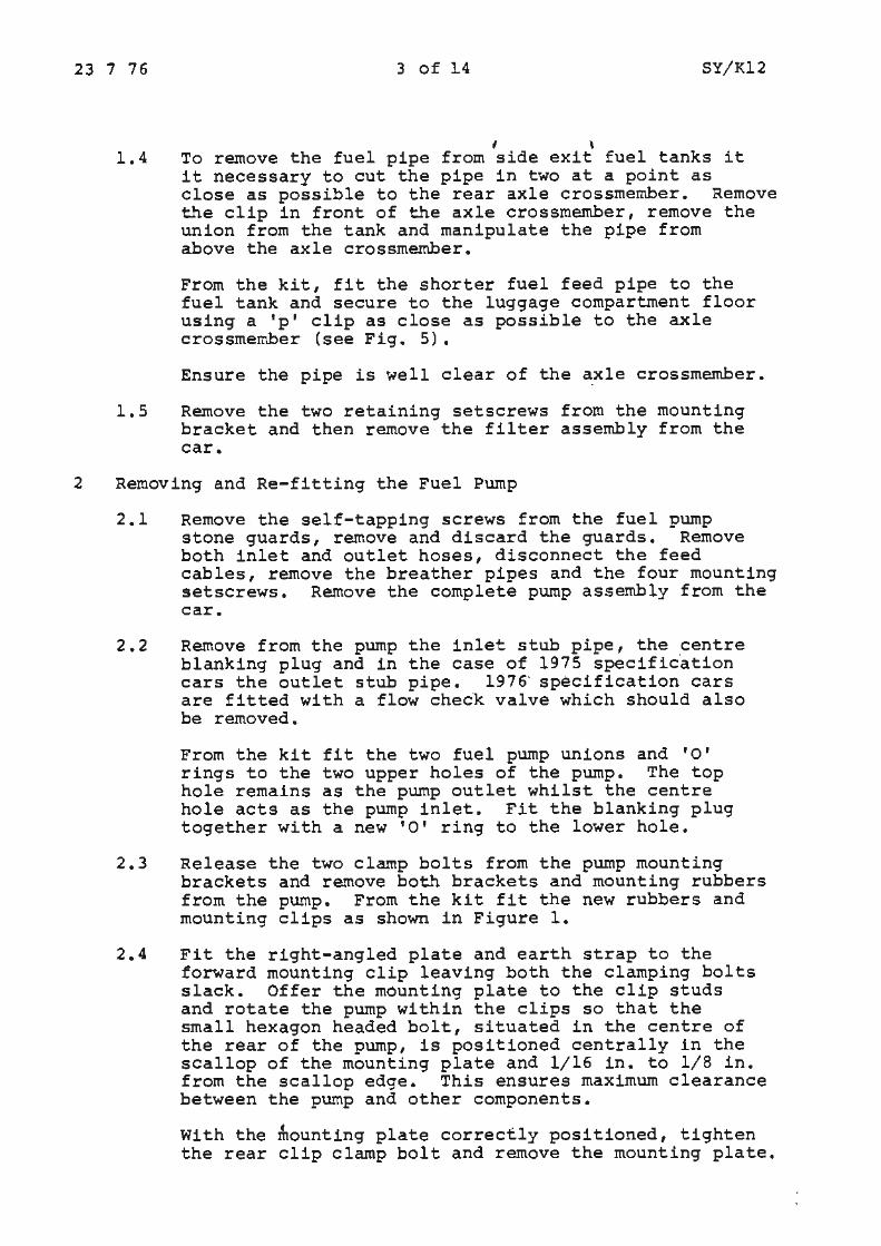
I \ 1.4 To remove the fuel pipe from side exit fuel tanks it
it necessary to cut the pipe in two at a point as close as possible to the rear axle crossmember. Remove the clip in front of the axle crossmember, remove the union from the tank and manipulate the pipe from above the axle crossmember.
From the kit, fit the shorter fuel feed pipe to the fuel tank and secure to the luggage compartment floor using a 'p' clip as close as possible to the axle crossmember (see Fig. 5).
Ensure the pipe is well clear of the ~xle crossmember.
1.5 Remove the two retaining setscrews from the mounting bracket and then remove the filter assembly from the car.
2 Removing and Re-fitting the Fuel Pump
2.1 Remove the self-tapping screws from the fuel pump stone guards, remove and discard the guards. Remove both inlet and outlet hoses, disconnect the feed cables, remove the breather pipes and the four mounting setscrews. Remove the complete pump assembly from the car.
2 . 2 Remove from the pump the inlet stub pipe, the centre blanking plug and in the case of 1975 specif ic'ation cars the outlet stub pipe. 1976· specification cars are fitted with a flow check valve which should also be removed.
From the kit fit the two fuel pump unions and 'O' rings to the two upper holes of the pump. The top hole remains as the pump outlet whilst the centre hole acts as the pump inlet. Fit the blanking plug together with a new 'O' ring to the lower hole.
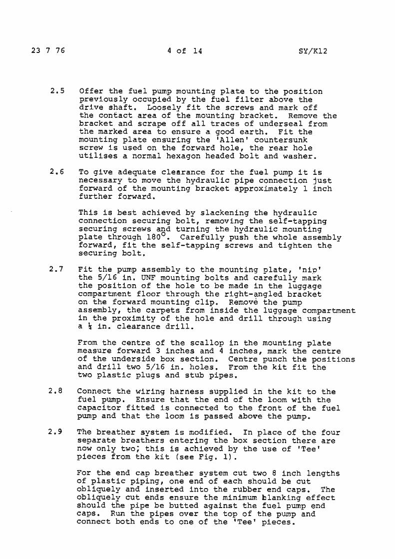
2.3 Release the two clamp bolts from the pump mounting brackets and remove both brackets and mounting rubbers from the pump. From the kit fit the new rubbers and mounting clips as shown in Figure 1.
2.4 Fit the right-angled plate and earth strap to the forward mounting clip leaving both the clamping bolts slack. Offer the mounting plate to the clip studs and rotate the pump within the clips so that the small hexagon headed bolt, situated in the centre of the rear of the pump, is positioned centrally in the scallop of the mounting plate and 1/16 in. to 1/8 in. from the scallop edge. This ensures maximum clearance between the pump and other components.
With the mounting plate correctly positioned, tighten the rear clip clamp bolt and remove the mounting plate.
23 7 76 4 of 14 SY/Kl2
2.5 Offer the fuel pump mounting plate to the position previously occupied by the fuel filter above the drive shaft. Loosely fit the screws and mark off the contact area of the mounting bracket. Remove the bracket and scrape off all traces of undersea! from the marked area to ensure a good earth. Fit the mounting plate ensuring the 'Allen' countersunk screw is used on the forward hole, the rear hole utilises a normal hexagon headed bolt and washer.
2.6 To give adequate clearance for the fuel pump it is necessary to move the hydraulic pipe connection just forward of the mounting bracket approximately 1 inch further forward.
This is best achieved by slackening the hydraulic connection securing bolt, removing the self-tapping securing screws and turning the hydraulic mounting plate through 180°. Carefully push the whole assembly forward, fit the self-tapping screws and tighten the securing bolt.
2.7 Fit the pump assembly to the mounting plate, 'nip' the 5/16 in. UNF mounting bolts and carefully mark the position of the hole to be made in the luggage compartment floor through the right-angled bracket on the forward mounting clip. Remove the pump assembly, the carpets from inside the luggage compartment in the proximity of the hole and drill through using a\ in. clearance drill.
From the centre of the scallop in the mounting plate measure forward 3 inches and 4 inches, mark the centre of the underside box section. Centre punch the positions and drill two 5/16 in. holes. From the kit fit the two plastic plugs and stub pipes.
2.8 Connect the wiring harness supplied in the kit to the fuel pump. Ensure that the end of the loom with the capacitor fitted is connected to the front of the fuel pump and that the loom is passed above the pump.
2.9 The breather system is modified. In place of the four separate breathers entering the box section there are now only two; this is achieved by the use of 'Tee• pieces from the kit (see Fig. 1).
For the end cap breather system cut two 8 inch lengths of plastic piping, one end of each should be cut obliquely and inserted into the rubber end caps. The obliquely cut ends ensure the minimum blanking effect should the pipe be butted against the fuel pump end caps. Run the pipes over the top of the pump and connect both ends to one of the 'Tee• pieces.
23 7 76 5 of 14 SY/Kl2
Cut a further length of approximately 10 inches and connect to the third leg of the 'Tee' piece. This length should run down the rear of the pump.
Connect two 4 inch lengths to the two centre breathers and connect to the remaining 'Tee' plece. A further length of 10 inches should be connected to the third leg of the 'Tee' piece and run down the rear of the pump.
2.10 Remount the fuel pump assembly and secure the rightangled bracket through the hole in the luggage compartment floor.
Mount the capacitor on the forward mounting clip stud, check the relative position of the hexagon headed bolt at the rear of the pump to the scallop in the mounting plate. Tighten the forward clamp bolt and the two mounting nuts.
Fit the inlet and outlet stub pipes from the kit to the fuel pump noting the inlet stub pipe is the longer of the two and has a more acute bend. Position the pipes to give the maximum clearance from the crossmember and tighten the union nuts.
Connect the fuel outlet from the tank by means of the 5 inch hose supplied in the kit.
Connect the pump outlet to the main supply line using the original hose.
Trim the breather pipes to a length as short as possible without the pipes 'kinking': connect them to the short plastic stub pipes previously fitted to the underside of the box section.
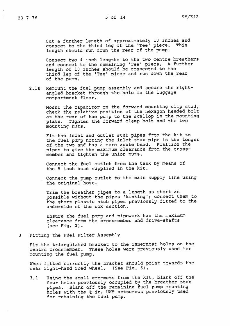
Ensure the fuel pump and pipework has the maximum clearance from the crossmember and drive-shafts (see Fig. 2).
3 Fitting the Fuel Filter Assembly
Fit the triangulated bracket to the innermost holes on the centre crossmember. These holes were previously used for mounting the fuel pump.
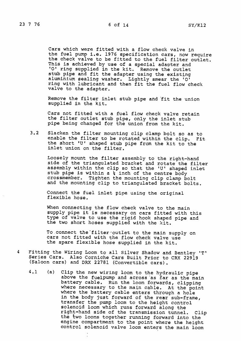
When fitted correctly the bracket should point towards the rear right-hand road wheel. (See Fig. 3).
3.1 Using the small grommets from the kit, blank off the four holes previously occupied by the breather stub pipes. Blank off the remaining fuel pump mounting holes with the\ in. UNF setscrews previously used for retaining the fuel pump.
23 7 76 6 of 14 SY/Kl2
Cars which were fitted with a flow check valve in the fuel pump i.e. 1976 specification cars, now require the check valve to be fitted to the fuel filter outlet. This is achieved by use of a special ada~ter and •o• ring supplied in the kit. Remove the outlet stub pipe and fit the adapter using the existing aluminium sealing washer. Lightly smear the 'O' ring with lubricant and then fit the fuel flow check valve to the adapter.
Remove the filter inlet stub pipe and 'fit the union supplied in the kit.
Cars not fitted with a fuel flow check valve retain the filter outlet stub pipe, only the inlet stub pipe being changed for the union from the kit.
3.2 Slacken the filter mounting clip clamp bolt so as to enable the filter to be rotated within the clip. Fit the short 'U' shaped stub pipe from the kit to the inlet union on the filter.
Loosely mount the filter assembly to the right-hand side of the triangulated bracket and rotate the filter assembly within the clip so that the 'U' shaped inlet stub pipe is within a\ inch of the centre body crossmember. Tighten the mounting clip clamp bolt and the mounting clip to triangulated bracket bolts.
Connect the fuel inlet pipe using the original flexible hose.
When connecting the flow check valve to the main supply pipe it is necessary on cars fitted with this type of valve to use the rigid hook shaped pipe and the two short hoses supplied with the kit.
To.connect the-filter·outlet to the main supply on cars not fitted with the flow check valve use the spare flexible hose supplied in the kit.
4 Fitting the Wiring Loom to all Silver Shadow and Bentley 'T' Series Cars. Also Corniche Cars Built Prior to CRX 22919 (Saloon cars) and DRX 22781 (Convertible cars).
4.1 (a} Clip the new wiring loom to the hydraulic pipe above the fuelpump and across 'as far as the main battery cable. Run the loom forwards, clipping where necessary to the main cable. At the point where the battery cable enters through a hole in the body just forward of the rear sub-frame, transfer the pump loom to the height control solenoid loom which runs forward along the right-hand side of the transmission tunnel. Clip the t:wo looms together running forward into the engine compartment to the point where the height control solenoid valve loom enters the main loom
23 7 76 7 of 14 SY/Kl2
adjacent to the right-hand toe board socket. Disconnect the white/slate lead from the top row of the toe board socket and re-connect the new feed wire.
Cut short the disconnected white/slate lead at the point where it enters the main loom, also cut short the original disconnected petrol pump loom where it enters the height control solenoid loom adjacent to the transmission tunnel and tape over where the disjointed leads previously entered the loom.
4.1 (b) Fitting the wiring loom to Corniche cars built from CRX 22919 (Saloon cars) and DRX 22781 (Convertible cars) •
The fuel pump wiring loom on the later Corniche cars differs from earlier cars with respect to the source of the supply. Unlike the earlier cars the supply now comes from within the luggage compartment, adjacent to the left-hand spring pot. It will be necessary to remove the two trim panels adjacent to the rear lefthand spring pot to gain access to the wiring connections.
Remove the original loom from the car after first disconnecting the green/black wire from the height control solenoid valve, also the green/black and the white wire adjacent to the left-hand spring pot inside the lugg~ge compartment.
From the pump run the new loom slightly forward of the pump to just rearwards of the hydraulic pipes which partially run across the width of the car. Secure the loom to the floor using the clips supplied in the kit. Run the loom across the car approximately 1 inch rearwards of the hydraulic pipes to the ·point at which the original loom was fitted; ensure the loom is adequately clipped. Run the green/black lead forwards to the height control solenoid valve, utilising the original clip holes to retain the loom and re-connect the height control solenoid valve.
I
Run the white fuel pump lead and solenoid lead rearwards, clipping the leads in the positions previously used for the original loom.
Feed the wire through the grommet in the luggage compartment floor, adjacent to the main battery feed cable. Connect the two leads to the fuel pump.and solenoid valve supply connections.
Fit the spring pot trim covers and replace the carpet.

23 7 76 8 of 14 SY/Kl2
5 Fitting the Fuel Cooler Assembly
5.1 Remove the carburetter air intake hose, ensure that the refrigeration system is fully discharged, disconnect the refrigeration return hose at the compressor and also at the rear of the left-hand spring pot. Remove and retain the two clips which retain the pipe to either side of the left-hand spring pot and remove the pipe from the car.
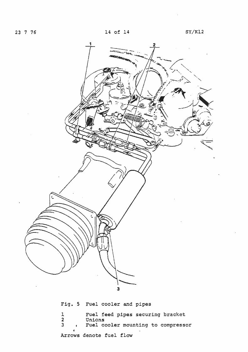
5.2 Remove the alternator mounting bracket bolt from the front of the compressor and then fit the cooler assembly mounting bracket to the front of the compressor.
5.3 Having ensured the refrigeration pipe 'O' rings are in good condition, fit the cooler/pipe assembly. The pipe assembly is clamped at the forward end of the cooler to the previously fitted mounting bracket using the two clips from the kit.
Using the original clips, clamp the pipe to the original position either side of the left-hand spring pot. Ensure that both connections are tight.
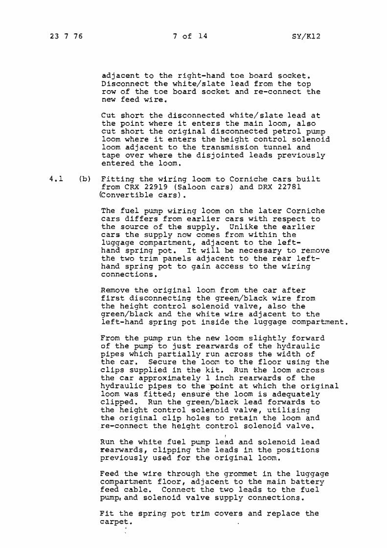
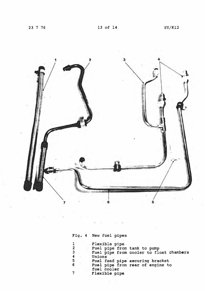
5.4 Disconnect the petrol supply pipe at the rear of the engine and at the carburetter float chambers then remove the pipe. From the kit, fit the petrol supply pipe from the rear of the engine to the fuel cooler a~sembly and the petrol supply pipe from the cooler to the carburetter float ·chambers (see Fig. 4). The connections to the fuel cooler utilises the two unions supplied in the kit.
Fit the small right-angled bracket {item~ s_of Fig. 4} to the~ in. UNF tapped hole which will be found to lie directly between the two pipes on 1 A' bank cylinder head. Using two •p• clips clamp the two petrol feed pipes to the right-angled bracket and tighten all connections.
s.s Reconnect the battery and switch on the ignition, ensure the fuel pumps are operating and check for any signs of petrol leaks.
Note: In the case of cars being fitted with a fuel flow check valve, changes to the electrical circuit ensure that the fuel pumps will not operate until engine oil pressure is present or the engine is cranking,
23 7 76 9 of l4 SY/Kl2
it is therefore necessary on these cars to disconnect the oil pressure switch during this test.
5.6 Fit the carburetter air intake hose, reconnect the oil pressure switch (on those cars affected) and start the engine, once again check for and rectify any signs of leakage.
5.7 Re-charge the refrigeration system as detailed in Chapter C of the Workshop Manual.
6 TIME ALLOWED
The time allowed for completing this operation is 14 hours.
Hly/DC
23 7 76 10 of 14 SY/Kl2
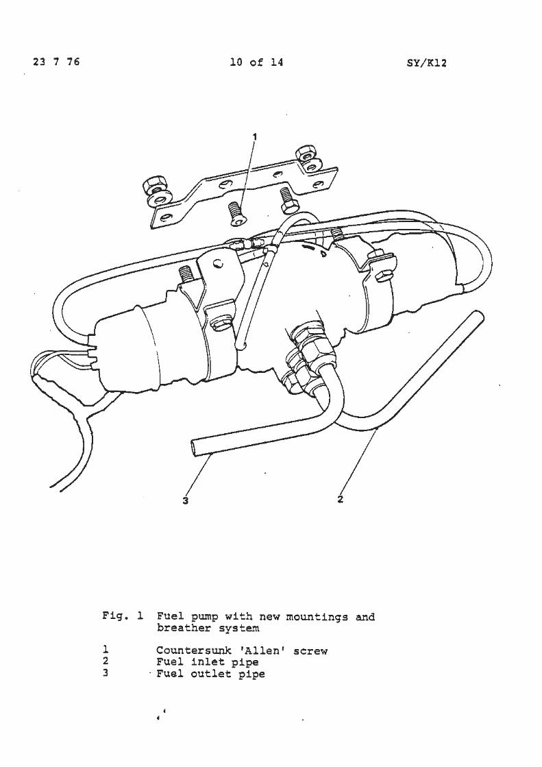
1
Fig. 1 Fuel pump with new mountings and breather system
1 Countersunk 'Allen' screw 2 Fuel inlet pipe 3 · Fuel outlet pipe
23 7 76
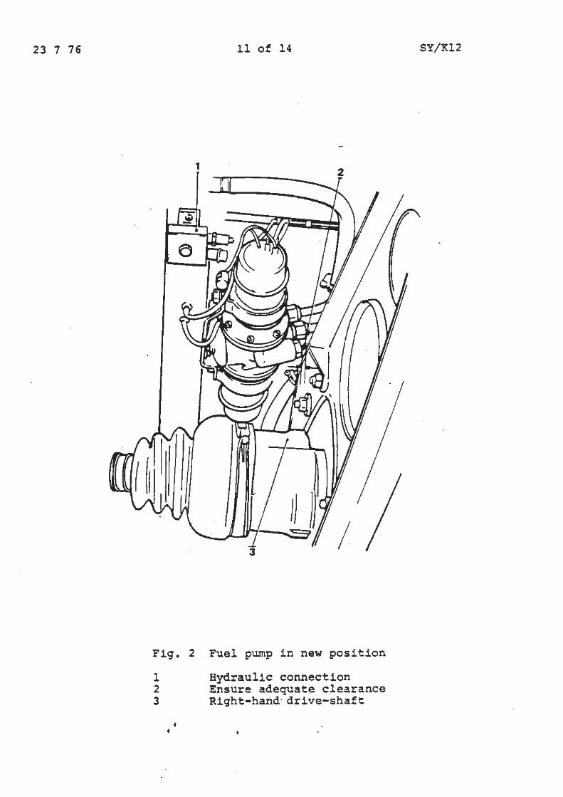
Fig. 2
l 2 3
1
11 of 14
2
Fuel pump in new position
Hydraulic connection Ensure adequate clearance Right-hand· drive-shaft
SY/Kl2
23 1 16
12 of 14
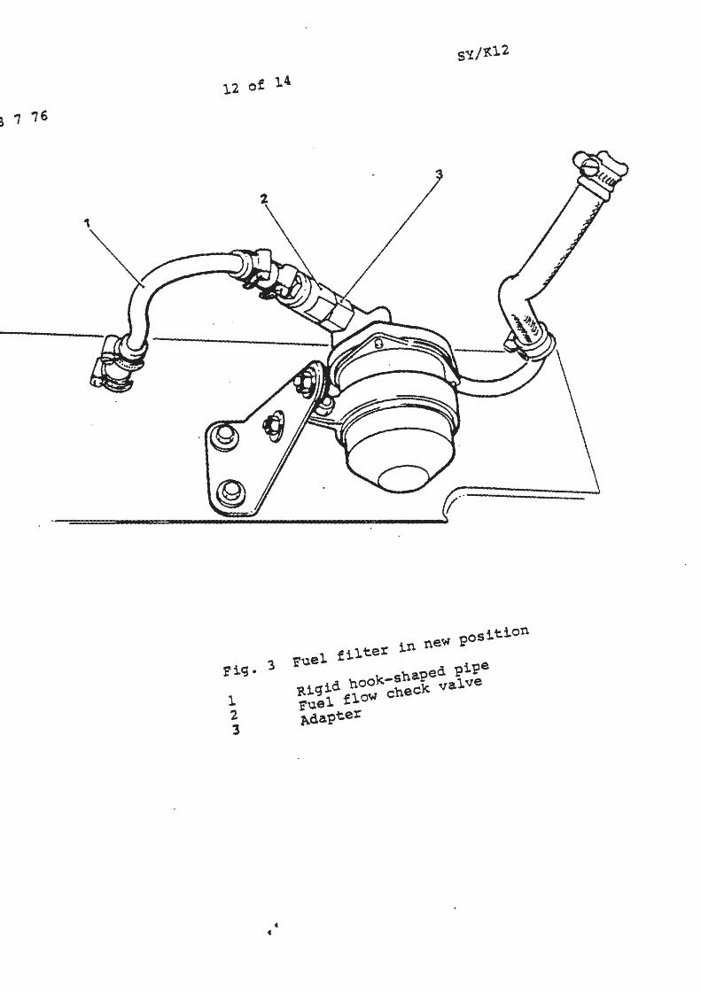
?ig. 3 ?uel filter in ne~ Fosition
l ~1gid hooK-shaFed FiFe 2 ?uel flo~ checK ~al~e
3 Adapter
• •
23 7 76
1
7
13 of 14 SY/I<12
2 3 4
-~
.,_
-· .... - ... ..,......- ._......... .I -
6 5
Fig. 4 New fuel pipes
1 Flexible pipe 2 Fuel pipe from tank to pump 3 Fuel pipe from cooler to float chambers 4 Unions S Fuel feed pipe securing bracket 6 Fuel pipe from rear of engine to
fuel cooler 7 Flexible pipe
23 7 76 14 of 14 SY/Kl2
3
Fig. 5 Fuel cooler and pipes
1 Fuel feed pipes securing bracket 2 Unions 3 • Fuel cooler mounting to compressor
f
Arrows denote fuel flow
Service Bulletin
Bullet.in number SY/Kl3
Circl.Aation list I 11 Category C
11
~LL D!STRIBUTORS ~..ND FETAILERS
FUEL LEVEL GAUGE TANK UNIT FLOATS
APPLICABLE TO:
Date 8 3 77 Pa ge~
11 II II 11 I
All Rolls-Royce Silver Shadow, Camargue and Corniche cars, and all Bentley T series and Corniche cars.
INTRODUCTION:
Replacement floats are now available for service use and obviate the necessity to change the entire tank unit.
DESCRIPTION:
fR{8~~E MOTORS
Car Division
TSD 4171
1 of 1
II
When a punctured plastic float is diagnosed it can now be :::-eplaced with a metal float part nurr~er L'E 40493.
This corrective action will prevent the unnecessary replacement of complete tank units.
A displaced punctured plastic float should be returned to the factory in the normal mar.ner for warranty consideration.
TIME ALLOWED:
1 Underfloor fuel tank - to replace tank unit float including removing and refitting the tank unit and all other associated work necessary -0.5 hours.
2 Behind rear seat tank - 1.0 hour.
I Service .Bulletins
Chapter L
~ Engine Cooling System
0 ;
Service Bulletin
Bulletin number SY /L20 Date 4 2 7f,
~8~ MOTORS
CMDMskln
Page 1 of 3
Circulation list I ! 11 I 11 11 II 11 I 11
Categoryc
TO ALL DISTRIBCTORS AND RETAILEH::i
MEASUREMENTS OF ANTI-FREEZE CONCENTRATION
.'\PP LI CABLE TO:
All Silver Shadow, T Series, Corniche and Camargue cars.
DESCRIPTION:
In the majority of cases hydrometers, used for checking anti-freeze concentration in the cooling system, are inaccurate due to their incapability of measuring more than a 40l concentration.
The acceptable service range of concentration is 45% to 55%.
A ~ore suitable instrument for measuring a 50% solution is a refra~troMeter called the 1 AO Duo-check' which is temperature co~pensated and also combines as a battery electrolyte tester.
T~ere are two models available which read in either Fahrenheit {Moc.el t-!o 7181) or Centigrade (Model No 7182).
These refractrometers are available from:
Britist l..rnerican Optical Co Ltd Instrument Group ~2!'l Yeovil Road S J.O\.i.gh Bucks
Tel: Slough 31351 Telex: 847234
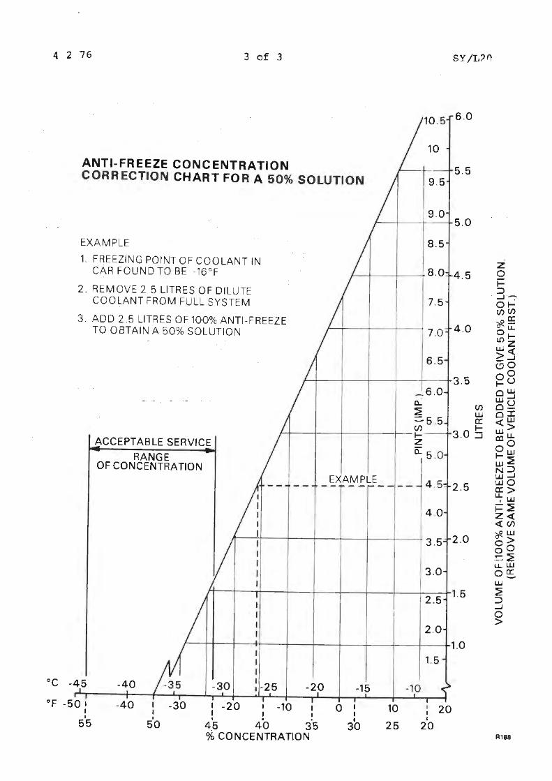
The graph at the end of this Service Bulletin will enable conve~sion of degrees of frost protection to a percentage ccncentration and also the necessary amount of coolant to be drained from the vehicles full cooling system to be replaced with 100% anti-freeze, should the system be less than the acceptable service limits.
4 2 76 2 of 3 SY/L20
Using 100% anti-freeze for topping up, in the amount incicated on the graph, will re-establish a 50% solution.
It should be noted that after adding a quantity of 100% antifreeze and prior to re-checking the solution concentration, the engine should he run at a fast idle f9r approximately 5 minutes to enable the 100% anti-freeze to be completely mixed with the existing solution. Failure to observe this o~eration will result in an incorrect reading.
It should be noted that all cars after those listed in Service Bulletin SY/Ll9 should only be topped up using Prestone r!T-184 anti-freeze. Prestone UT-184 is supplied in 1 gallon containers marked "Prestone" with no reference to UT-184, for the present this will continue until the introduction of metric containers when the designation UT-184 will be oisplayed on the side of the container.
Prestone UT-184 and anti-freeze solutions to BS 3150 can be interchanged providing the cooling system is thorouahly flushed.
4 2 76 3 of 3 SY/L::>0
ANTI-FREEZE CONCENTRATION CORRECTION CHART FOR A 50% SOLUTION
EXAMPLE
1. FREEZING POINT OF COOLANT IN CAR FOUND TO BE -16°F
2. REMOVE 2 .5 LITRES OF DILUTE COOLANT FROM FULL SYSTEM
3. ADD 2 .5 LITRES OF 100% ANTI-FREEZE TO OBTAIN A 50% SOLUTION
10.5 6.0
10
5.5 9.5
9.0 5.0
8.5
. 8.0 4.5
7.5
I 7.0 4.0
6.5
_ 6.0 0... ~
ACCEPTABLE SERVICE
RANGE
::::. 5 . 5 (/)
1---+-~-+-- +---t- 1-
(/) w ex:: 1-
3.0 ::i z 0:: 5 .0
OF CONCENTRATION
_EXAMPr---- 4 .5 2.5
4 .0
l't----:..+----+---t-~+------1---r---rl 3.5 2.0
130 2.5 1.S
2.0
1.0 I I 1.5 I oc -45 -40 -30 I , -25 -20 -15 -10
°F -50 1 -40 -30 I -20 I -10 0 10 I 20 I I I I I I I • . . • 25 20 55 50 45 40 35 30
% CONCENTRATION R188
Service Bulletin
Bulletin number SY/L 22
C1rculat1on list I I 11
Category C
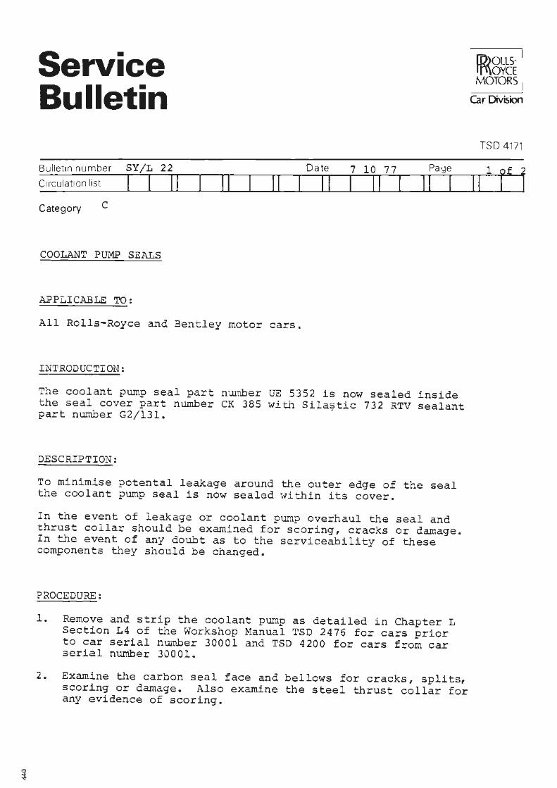
COOLANT PUMP SEALS
APPLICABLE TO:
II 11
All Rolls-Royce and Bentley motor cars.
INTRODUCTION:
Date 7 10 77 Page
II I II I II I
The coolant pump seal part number UE 5352 is now sealed inside the seal cover part nwnber CK 385 with Sila~tic 732 RTV sealant part number G2/l31.
DESCRIPTION:
To minimise potental leakage around the outer edge of the seal the coolant pump seal is now sealed within its cover.
In the event of leakage or coolant pump overhaul the seal and thrust collar should be examined for scoring, cracks or damage. In the event of any doubt as to the serviceability of these components they should be changed.
PROCEDURE:
1. Remove and strip the coolant pump as detailed in Chapter L Section L4 of tile Workshop Manual TSO 2476 for cars prior to car serial nw-nber 30001 and TSD 4200 for cars from car serial number 30001.
2. Examine the carbon seal face and bellows for cracks, splits, scoring or damage. Also examine the steel thrust collar for any evidence of scoring.
ID>OLLSrf\\oYCE MOTORS
Car Division
TSO 4171
II
7 10 77 2 of 2 SY/L 22
3. Lightly degrease the outer edge of the seal and the inner edge of t.~e saal cover.
Note - Ensure that the seal is not saturated in degreaser as this could have a detrimental effect on the rubber and the bonding of the carbon seal to the rubber bellows.
4. Apply a thin coat of 11Silastic 11 to the inner edge of the seal cover, allow approximately 10 minutes before pressing the seal into the seal cover.
5 . Reassemble the coolant pu.~p as described in Section L4 of the relevant Workshop Manual.
Hly/DC
0
Service Bulletin
Bulletin number SY/L23 C1rculat1on list I II Category C
II
ALL DISTRIBUTORS ANO RETAILERS
HEATER TAP FEED HOSE
Date 17 11 77
II 11 I II I
APPLICABLE TO: All Rolls-Royce and Bentley motor cars from car serial number SRF 30001
INTRODUCTION:
Page
11 I
It is recommended that the heater tap feed hose is changed at 40,000 km. (24,000 mile) intervals. It is important to ensure that the flow through the heater hose connecting the engine to the heater tap is completely unrestricted.
JR{g~E MOTORS
Car Division
TSO 4171
1 of 1
11 I
Restriction can be caused by a sharp radius or bend in the hose, contact with other adjacent pipework, or poor alignment.
DESCRIPTION:
During seasonal servicing which franchise holders should now be reconunending, ensure that the heater hose is at least 12.7 mm, {0.500 inches) clear of any other adjacent pipework. If necessary carefully re-align the hose to ensure these clearances are correctly maintained and the hose is free from any sharp bend or radius.
Hly/DC
! C
i
Service Bulletins
Chapter M Electrical System
;::. "' 7
0
Service Bulletin
I ID>OLLS· I rt'\OYCE MOTORS
Car Division
Date 4 2 76 Pa ge l of 2
11 I
Category C
TO DISTRIBUTORS AND RETAILERS
REPLACEMENT BLOWER MOTORS
APPLICABLE TO:
11 11 11 11 I 11
All Rolls-Royce Silver Shadow and Coachbuilt cars and all Bentley T Series and Coachbuilt cars produced prior to car serial number SRX 6000.
DESCRIPTION:
The above cars are fitted with two wire wound field blower motors, part number UD 8909. Replacement motors of this type are no longer available and permanent magnet field motors will be supplied for all replacement purposes.
However, due to certain internal differences between the two types of motor, it is not possible to fit one of each type on the same car. It will therefore be necessary to replace both blower motors, and as the motor shafts are not the same size, it "'ill be necessary to change the rotors.
To ensure correct operation it will also be necessary to fit a special relay to the right hand blower motor.
All necessary components to replace an early type of motor are contained in kit number RH 2650.
PROCEDURE:
1. Replace both motors and rotors. Retain the motor which has not failed for future use.
2. Connect the cables to the left hand motor such that the motor will operate in a clockwise direction.
3. Fit the relay provideo in a convenient location adjacent to the right hand motor.
4. Of the two. cables originally connected to the motor, connect one cable to terminals 7 and A of the relay. Connect the second cable to terminal 9 of the relay.
5. Csing a suitable length of cable connect terroinal B of the o relay to a suitable earth point. 3
Ill ,-m .... "O ~
E ..3 t 0 0 ~ QI u > 0 a: "' 0 a: g
4 2 76 ?. of ?.
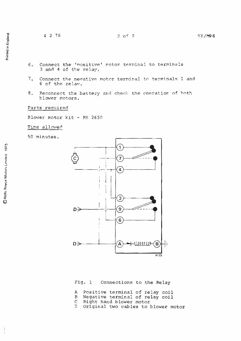
6. Connect the 'nosi ti ve ' rotor te rminal to tennina l s 3 an~ 4 of t he re l ay.
7 . Connect the neaativ~ Mo t0r terminal tn ter~inal s 1 and 6 of the relav.
8 . P.econnect t he battery and ched: the 0pera tior. of. h0th blower motors .
Parts required
Blower motor kit - PH 2650
Time allowec!
50 minutes.
0:;;,1'----
,,.
~1 23
Fig. 1 Connections to the Relay
A Positive terminal of re l ay coil B Negative terminal of re lay coil C Right hand blower moto r D Original two cables to blower motor
SY /M9 8

Service Bulletin
' ID>ousff'\ovcE I MOTORS i
CarDMsion
TSO 4171
Bulletinnumber SY/M99 (Issue 2) Date l 7 77 Pa ge 1 of 3
1 i ~ ., IS
Circu+at1on list I I 11 11 11 I I II II I 11 I Category C
TO ALL DISTRIBUTORS AND RETAILERS
PIPER WINDOW LIFT !-lOTOR LL?.1IT SWITCHES
APPLICABLE TO:
All Rolls-Royce 2 door and Corniche cars, and all Bentley T Series 2 door and Corniche cars prior to car serial numbers CRH 22648, CRX 22919, DRH 22583, DRX 22781 but including CRH 21998 and CRX 21729.
j DESCRIPTION: f > * ~*The existing switch PWlll20 i.s to be replaced by switch UG 4049 j whi ch is included in kit RH 2691 together with the necessary @ washers.
..
The following procedure should be carried cut with the window lift motor assembly removed from the car as described in Chapters - Body, of the Workshop Manual TSD.~476.
PROCE=1:JRE:
Figure l shows the new CG 4049 switches fitted to the window lift asser..bly. However, va r iances of the wincow lift motor asse~bly are available i .e. opening rear quarter light, but the sa~e general pr inciples can be applied to all cases in the positioning of the switch.
1 Using Figure 1 a~ a guide, mark the centre line of the existing switch(FW 11120} plunger on to the lower sprocket •
2 Remove the faulty switch.
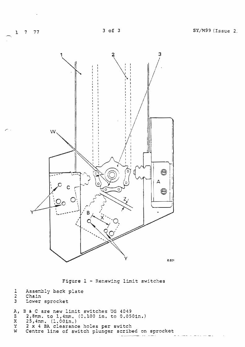
3 Usinq Figure las a guide, mount the switch allowing 2,8mm. to l,4rr.m. (O.lOOin. to O.OS Oin.) clearance between the stainless steel switch plunger and the chain. No part of the switch should overhang the base plate.
. 1 7 77 2 of 3 SY/M99 ( Issue 2}
4 Clamp the switch to the assembly base plate and drill two 4BA clearance holes 25,4mm. (l.OOin) between centres.
5 Fit the switch using setscrew UA 11485 (2 off), washers X8811 (4 off) and nuts UA 11403 (2 off).
Use washers X4404 as spacers between the switch and base plate to ensure correct switch plunger to chain aligr..ment. Lubricate the switch plunger with an approved grease.
6 The wiring remains unchanged. Cables to switches Band c {see Fig. 1) are attached to terminals 1 and 2 marked on each switch.
PA..~':'S R.E QUlRED:
Switch Kit RH 2691
T n!E ALLOWED :
Remove and renew cr.e switch - 0.3 hour.
*Re-issued to a.11end an incorrect part n-..lr:tber quoted for original switch.
, .
1 7 77
,
--- . __ ......
C -·· '
y I ' ' - - ,. ... J , ____ _
.. ' '''•\ "\ ;I
.. .J • •••••• :
3 of 3
2
\
I I I I I
I I
y
3
~ A
~
Figure l - Renew~ng limit switches
l Asse~~ly back plate 2 Chain 3 Lower sprocket
}., B & C are new limit s·..,itches UG 40·49 Z 2,B~m. to 1,4mm. (0.100 in. to O.OSOin.) X 25,4mm. (l.OOin.) Y 2 x 4 BA clearance holes per switch
uo,
w Centre line of switch plunger scribed on sprocket
SY/M99 (Issue 2:
Service Bulletin
Bulletm number
Category C
16W WIPER MOTOR PARKING SWITCH ADJUSTMENT
APPLICABLE TO:
.~All Silver Shadow, T series and Corniche motor cars fitted with ~ an intermi tten wipe device. § ] ...J ., ~ DESCRIPTION: ~ 4'
JFor same time the wiper motbr type 16W has been reduced for ·Jspares purposes to three sub-assemblies, as described in £Service Bulletin SY/M49. The 16W motor can be recognised 9by the round motor casing as opposed to the flat sided casing
of the previous motor.
For general fault diagnosis of this wiper motor, consult Service Bulletin SY/MBB.
The parking switch of this motor is provided with an adjustment to allow for slight dimensional differences in motor and drive gear assemblies. When replacing a drive gear assembly it may be necessary to re-adjust the parking switch to suit the new assembly. Failure to do this may result in one of the following faults:
1 With the wiper switch in the INTERMITTENT position and the blades parked on the screen, moving the switch to the OFF position does not cause the blades to move to the off screen position.
2 When moving the wiper switch from OFF to INTERMI'rl'ENT, there is an 8 to 10 second delay before the wiper motor operates.
If a new gear assembly has been fitted and the wiper motor exhibits one of the above faults the relevant following procedure should be adopted.
TSD4171
16 2 76 2 of S SY/MlOO
NOTE Always ensure that the metal top plate is in position and the parking switch securing screws are tight before operating the motor.
PROCEDURE FOR FAULT 1
l Unscrew the rack tube nut and release the clait,p from the wiper motor.
2 Rotate the motor until the parking switch is accessible (see Figure l). Tighten the rack tube nut. This will allow the motor to be operated and also permit adjustment of the switch.
3 Switch on the ignition and slacken the parking switch secl.U'ing screws and move the parking switch fully inwards towards the gearwheel. Select INTERMITTENT wipe, and once the blades have moved, select OFF. The motor will not reverse and park.
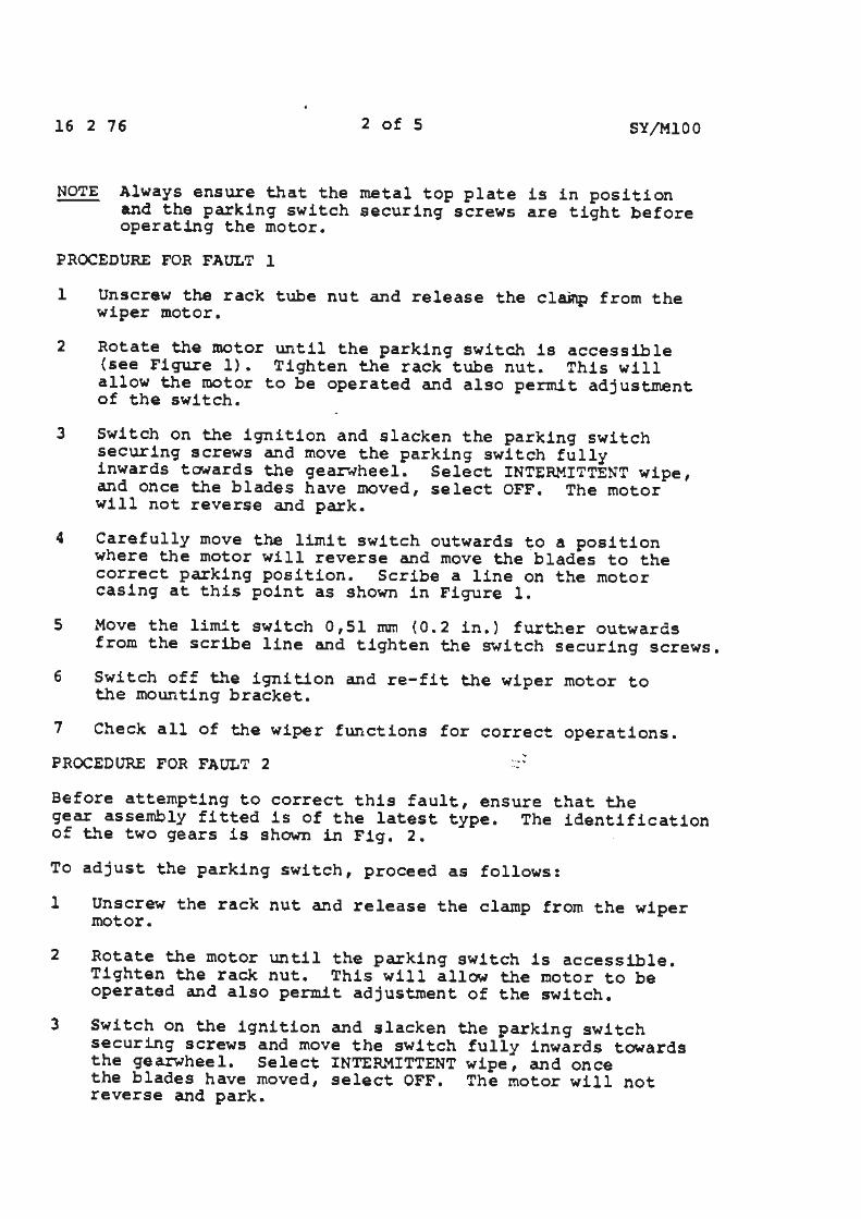
4 Carefully move the limit switch outwards to a position where the motor will reverse and move the blades to the correct parking position. Scribe a line on the motor casing at this point as shown in Figure l.
5 Move the limit switch 0,51 mm (0.2 in.) further outwards from the scribe line and tighten the switch securing screws.
6 Switch off the ignition and re-fit the wiper motor to the mounting bracket.
7 Check all of the wiper functions for correct operations.
PROCEDURE FOR FAULT 2 -....... ..•
Before attempting to correct this fault, ensure that the gear assembly fitted is of the latest type. The identification of the two gears is shown in Fig. 2.
To adjust the parking switch, proceed as follows:
l Unscrew the raek nut and release the clamp from the wiper motor.
2 Rotate the motor until the parking switch is accessible. Tighten the rack nut. This will allow the motor to be operated and also permit adjustment of the switch.
3 Switch on the ignition and slacken the parking switch securing screws and move the switch fully inwards towards the gearwheel. Select INTERMITTENT wipe, and once the blades have moved, select OFF. The motor will not reverse and park.
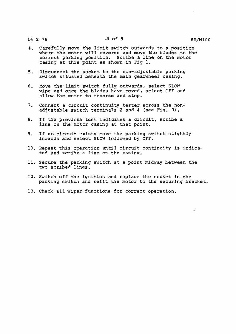
16 2 76 .3 of 5 SY/MlOO
4. Carefully move the limit switch outwards to a position where the motor will reverse and move the blades to the correct parking position. Scribe a line on the motor casing at this point as shown in Fig 1.
s. Disconnect the socket to the non-adjustable parking switch situated beneath the main gearwheel casing.
6. Move t.he · lirnit switch fully outwards, select SLOW wipe and once the blades have moved, select OFF and allow the motor to reverse and stop.
7. Connect a circuit continuity tester across the nonadjustable switch terminals 2 and 4 (see Fig. 3).
B. If the previous test indicates a circuit, scribe a line on the motor casing at that point.
I
9. If no circuit exists move the parking switch slightly inwards and select SLOW followed by OFF.
10. Repeat this operation until circuit continuity is indicated and scribe a line on the casing.
11. Secure the parking switch at a point midway between the two scribed lines.
12. Switch off the ignition and replace the socket in the parking switch and refit the motor to the securing bracket.
13. Check all wiper functions for correct operation.
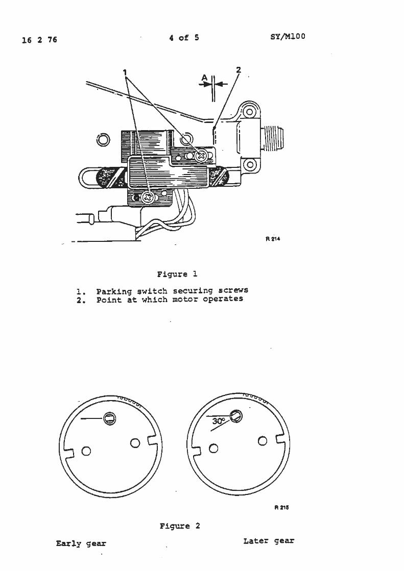
16 2 76 4 of S
2
Figure l
l. Parking switch securing screws 2. Point at which motor operates
-~ 0
0
Figure 2
SY/MlOO
A 215
Early gear Later gear
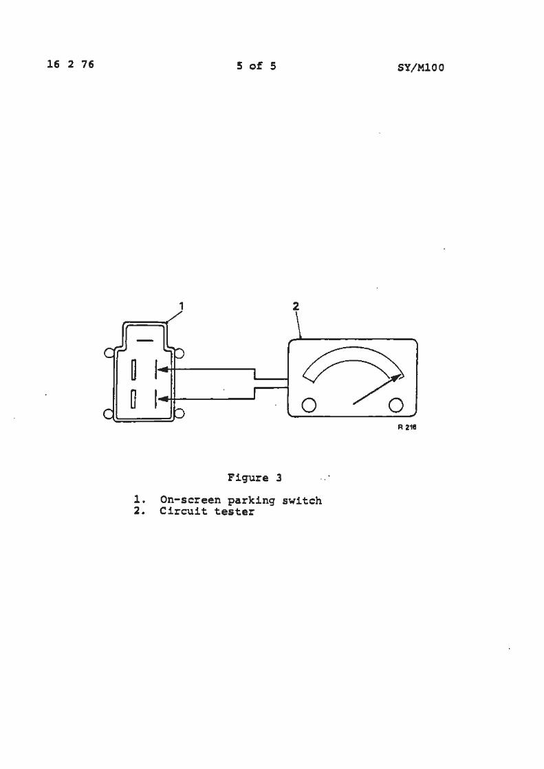
16 2 76 S of 5 SY/MlOO
1 2
0 R 218
Figure 3
1. On-screen parking switch 2. Circuit tester
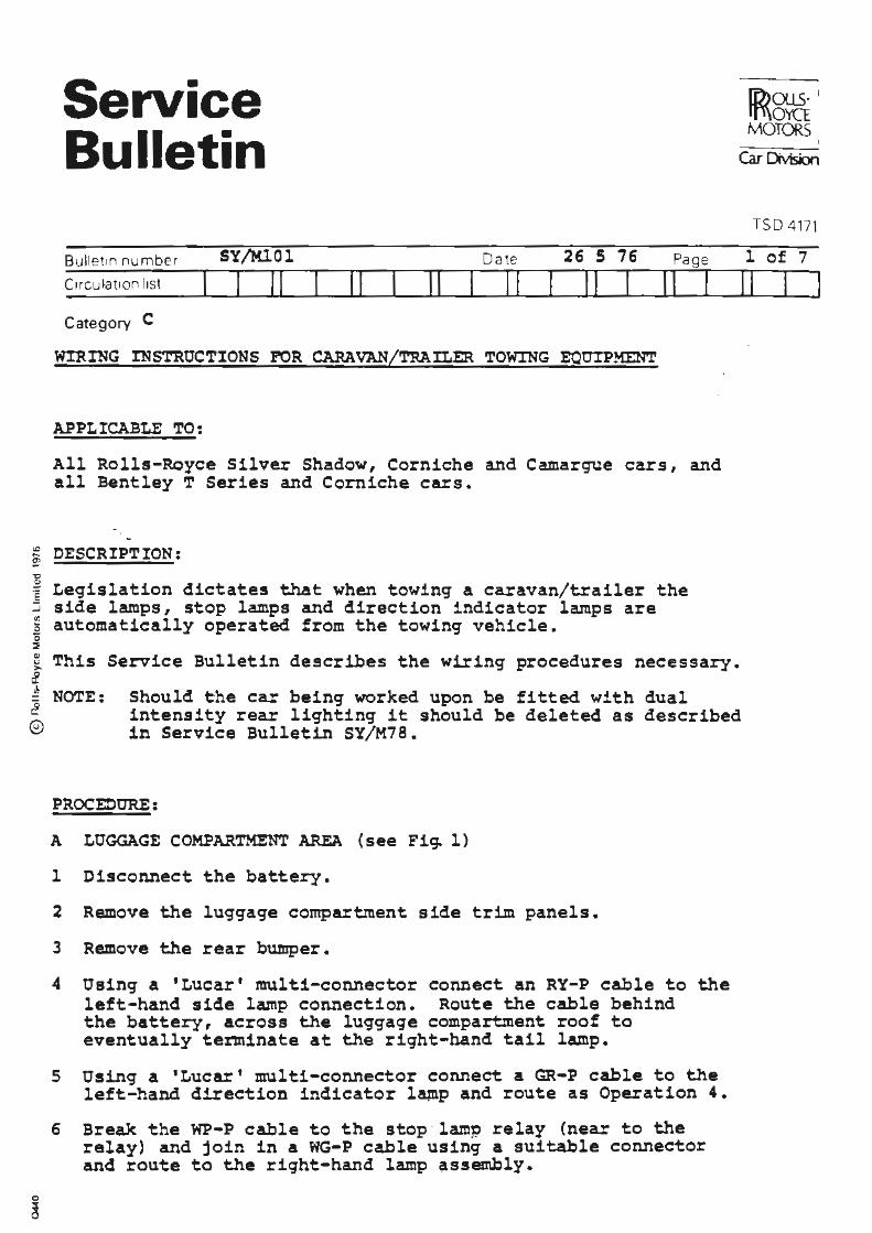
Service Bulletin
Bulletin number SY/M.101
C1rcufat1on hst I II Category C
Date 26 S 76
II II 11 II I
WIRING INSTRUCttONS FOR CARAVAN/TRAILER TOWING EQUIPMENT
APPLICABLE TO:
Page
II I
All Rolls-Royce Silver Shadow, Corniche and Camargue cars, and all Bentley T Series and Corniche cars.
:e DESCRIPTION: !!? .., ] Legislation dictates that when towing a caravan/trailer the ~ side lamps, stop lamps and direction indicator lamps are 5 automatically operated from the towing vehicle . ~
(E))Ol.15 I
I rf\\OYCT I MOTORS I
Car Dtvision
TSD 4171
l of 7
II
[ This Service Bulletin describes the wiring procedures necessary. ,£
i NOTE: Should the car being worked upon be fitted with dual intensity rear lighting it should be deleted as described in Service Bulletin SY/M78. ©
PROCEOURE:
A LUGGAGE COMPARTMENT AREA { see Fig. 1)
l Disconnect the battery.
2 Remove the luggage compartment side trim panels.
3 Remove the rear bumper.
4 Using a 'Lucar' multi-connector connect an RY-P cable to the left-hand side lamp connection. Route the cable behind the battery, across the luggage compartment roof to eventually terminate at the right-hand tail lamp.
5 Using a 'Luca.r' multi-connector connect a GR-P cable to the left-hand direction indicator la+np and route as Operation 4.
6 Break the WP-P cable to the stop · lamp relay (near to the relay) and join in a WG-P cable using a suitable connector and route to the right-hand lamp ~sseml,ly.
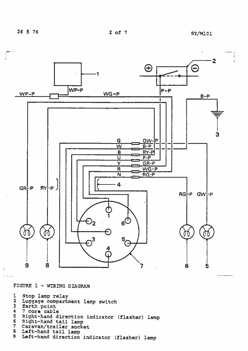
I I J
26 5 76
--~
--1
WP-P WP-P
GR-P
9 8
FIGURE l - WIRING DIAGRAM
1 Stop lamp relay
2 of 7
WG-P
Y GR-P R WG·P N RG-P
7
2 Luggage co~artment la.mp switch 3 Earth point 4 7 core cable 5 Right-hand direction indicator (flasher) lamp 6 Right-hand tail lamp 7 Caravan/trailer socket 8 Left-hand tail lamp 9 Left-hand direction indicator (flasher) lamp
P-P
SY/MlOl
=1 I .
---2 I
e
B-P
---I 3
RG-P GW ·P
6 5
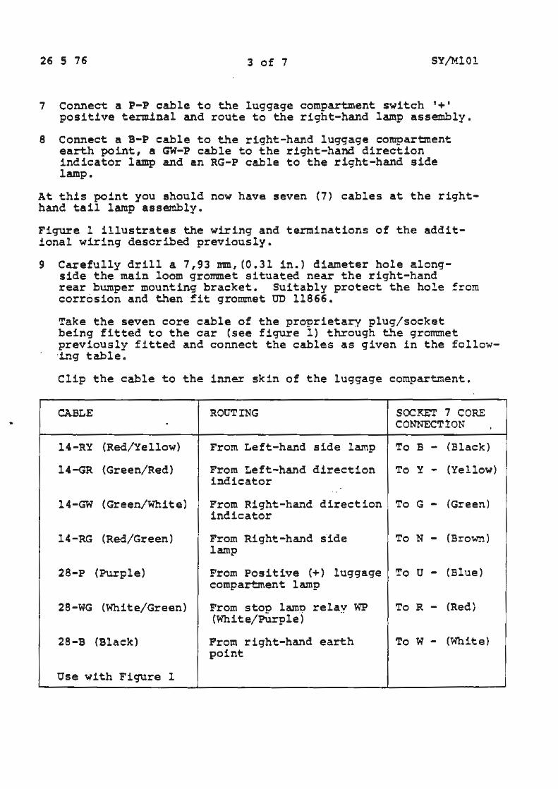
•
26 5 76 3 of 7 SY/MlOl
7 Connect a P-P cable to the luggage compartment switch'+' positive terminal and route to the right-hand lamp assembly.
8 connect a B-P cable to the right-hand luggage compartment earth point, a GW-P cable to the right-hand direction indicator lamp and an RG-P cable to the right-hand side lamp.
At this point you should now have seven (7) cables at the righthand tail lamp assembly.
Figure 1 illustrates the wiring and terminations of the additional wiring described previously.
9 Carefully drill a 7,93 mm, (0.31 in.) diameter hole alongside the main loom grommet situa~ed near the right-hand rear bumper mounting bracket. Suitably protect the hol e !rom corrosion and then fit grommet UD 11866.
Take the seven core cable of the proprietary plug/ socket being fitted to the car (see figure 1) th.rough the grotmnet previously fitted and connect the cables as given in the follow·ing table.
Clip the cable to the inner skin of the luggage compartment.
CABLE ROUTING SOCKET 7 CORE . CONNECT!ON
l .4-RY (Red/ Yellow) From Left-hand side l amp To B - (Black)
14-GR (Green/Red) From Left-hand direction To y - (Yel l ow) indicator . ..
14-GW (Green/White) From Right-hand direction To G - (Green) indicator
14-RG (Red/Green) From Right-hand s·ide To N - (Brown) lamp
28-P (Purple) From Positive (+) luggage To u - (Blue) compartment lamp
28-WG (White/Green) From stoo lame relav (White/Purple) ··
WP To R - (Red )
28-B (Black) Prom right-hand earth To W - (White) point
Use wi th Figure l
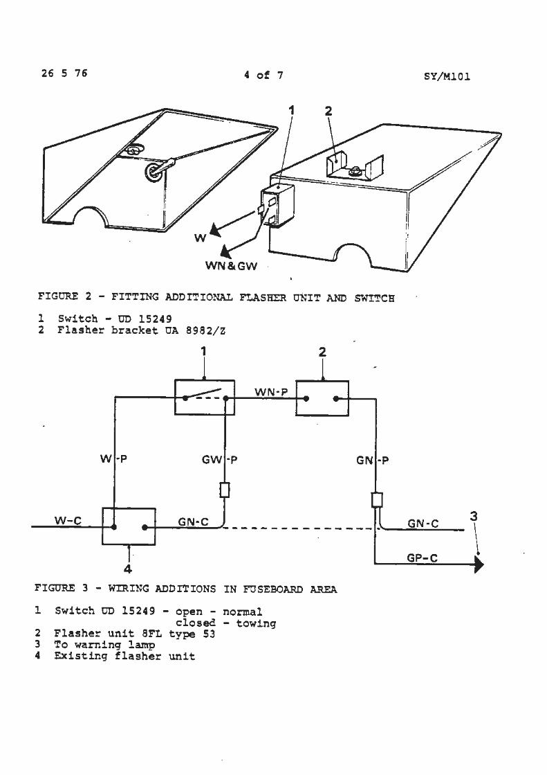
26 5 76 4 of 7 SY/MlOl
WN&GW ·
FIGURE 2 - FITTING ADDITIONAL FLASHER UNIT AND SWITCH
l Switch - OD 15249 2 Flasher bracket OA 8982/Z
1 2
WN·P
W ·P GW·P GN ·P
w-c GN·C GN·C ~~-------------~------- ----·----------4
FIGURE 3 - WIRING ADDITIONS IN FOSEBOARD A.REA
l Switch OD 15249 - open - normal closed - towing
2 Flasher unit 8FL type 53 3 To warning la.mp 4 Existing flasher unit
GP-C
3
\
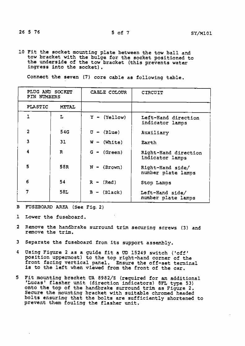
26 S 76 5 of 7 SY/MlOl
10 Fit the socket mounting plate between the tow ball and tow bracket with the bulge for the socket positioned to the underside of the tow bracket (this prevents water ingress into the socket).
Connect the seven (7) core cable as following table.
PLUG ANt) SOCKET CABLE COLOUR PIN NOMBERS
PLASTIC METAL
l L y - (Yellow)
2 54G 0 - (Blue)
3 31 w - (White)
4 R G - (Green)
s 58R N - {Brown)
6 54 R - (Red)
7 SSL B - {Black)
B FOSEBOARD AREA (See Fig. 2)
1 Lower the fuse.board.
CIR.COIT
Left-Band direction indicator lamps
Auxiliary
Earth
Right-Hand direction indicator lamps
Right-Hand side/ number plate lamps
Stop Lamps
Left-Band side/ number plate lamps
2 Remove the handbrake surround trim securing screws (3) and remove the trim.
3 Separate the fuse.board from its support assembly.
4 Using Figure 2 as a guide fit a O'O 15249 switch ('off' position uppermost) to the top right-hand eorner of the front facing vertical panel. Ensure the off-set ter:::ninal is to the left when viewed from the front of the car.
S Fit mounting bracket UA 8982/Z (required for an additional •Lucas' flasher unit (direction indicators} 8FL type 53} onto the top of the handbrake surround trim as Figure 2. Secure the mounting bracket with suitable chromed headed bolts ensuring that the bolts are sufficiently shortened to prevent them fouling the flasher unit.
26 5 76 6 of 7 SY/MlOl
C FUSEBOARD CHANGES (See Pig. 3)
1 Osing Figure 3 as a guide break the GN-C cable and solder female Luea.r connectors to the bared ends.
2 Take a GW-P cable fitted with female 'Lucar' connections from. the flasher unit end of the GN-C cable. Route this cable to terminate above the handbrake.
3 With a suitable connection connect the remaining end of the GN-C cable to a GN-P cable and route this to terminate above the hand.brake.
4 Connect a W-P ea.ble to a W-C cable at the flasher unit terminal and take the remaining end to terminate above the hand.brake.
At this point you should now have three (3) cable ends above t..~e hand.brake.
5 Disconnect the GP-C wire from the flasher unit plug and, using a suitable connection, connect it to the GN-P cable from the additional flasher unit.
Connect the switch and additional flasher unit as follows:
6 Fit the 8FL type 53 (green) flasher unit into its bracket fitted to the handbrake surround tril'tl.
7 Connect a short WN-P cable between one terminal of the flasher unit and the centre terminal of the switch (use a double 'Lucar• connector}.
8 Connect the three cables com~leted at Operation 4 as follows: .
a) GW-P cable to the double 'Lucar' (see Operation 7) at switch.
b) GN-P cable to the remaining flasher unit connection.
e) W-P cable to the switch top connection.
0 TESTING
Connect the battery and, using a 12 Volt 21 Watt. lead lamp, earth the lamp into terminal number 3 of the socket. Check all connections/functions described in the wiring chart, noting that when the direction indicators (flashers) operate the rate of 'flash is between 60 and 120 per minute with the change-over switch operative.
With the test lamp removed and the change-over switch in the 'off' position, check that all the lamps function.
Oiseonneet the battery.
26 5 76 7 of 7
E FINISHING
1 Fit the luggage compartment side panels.
2 Fit the rear bumper.
3 Fit the handbrake surround trim and fuseboard.
4 Connect the battery.
SY/MlOl
The foregoing information has been written based on a right-hand drive four door saloon. The siting of various components may have to be varied for other models, but the wiring in the main remains the same. F.or instance on the Cama.rgue the flasher unit for the direction indicators is not situated on the fuseboard but on a bracket adjacent to the steering column. Also, left-hand drive models have a parking brake fitted instead of the handbrake mentioned in the instructions. It is essential however on coachbuilt cars, that the relevant wiring diagrams are consulted, as the cable colours differ on these cars from those on the four door saloon.
F TntE ALLOWED
Fitting complete kit - 7.0 hours
Service Bulletin
l lv>OLLS· I ' lf\\OYCE ! MOTORS ! I
CarDMsion
Bulletin number
Circ~t1on 11st
Category C
~..LL DISTRIBUTORS AND RETAILERS OT=ER TH~ USA J..ND CANADA
CHLORIDE BATTERY 369/6-~'i'Zl3R
<.o ?-.?PLICA.BLE ';.'0: ; i :~ ..J
"' 0 0 ::i'
All Rolls-~oyce Silver Shadow, Corniche and Carr.argue ~otor cars, and all Bentley T Series and Ccrniche motor cars •
j !~!TPCDCCTim!:
"' £ The Dageni te Demon battery has been s upersec.ed by the Chloride @) 369/6-TWZ13R battery on all motor cars from car serial nu.r:ber
25662. Ecwever it should be noted that certain earlier motor cars r.:ay be fitted with Chloride batteries.
CESCR!PTIO:I:
The new Chlo=ide battery is similar in appearance to the Lucas Pa: c.er.:.e.i<er battery. It has a sirr.ilar polypropylene type case, but it has a black top and six white vent plugs, as opposed to a red top and filler trough cover.
The case of the new Chloride battery is snaller in c.ir.,ensicn t..11.an that of the now SU?erseded Dagenite Cemon battery, and ~ay be ~sed :or all replacenent purposes, providing the prccecu~es given er. Fase 3 are carried cut. However, it is recorr.mended that when using a Chloride battery for replacenent 9urposes, the label is re~oved fron the battery box cover, as the information on this label relates onll'· to the Dageni te C·er,cn battery.
* P.e-is s ue<i to delete reference to label now no lonc;er available.
TSO 4171
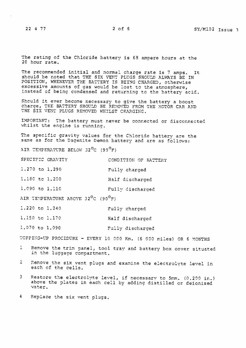
22 4 77 2 of 6 SY/MlO 2 Issue '3
The rating of the Chloride battery is 68 ampere hours at the 20 hour rate.
The reco~.rnended initial and normal charge rate is 7 amps. It should be noted that THE SIX VENT PLUGS SHOULD ALWAYS BE IN POSITION, WHENEVER THE BATTERY IS BEI~G CHA.RGED, otherwise excessive amounts of gas would be lost to the atmosphere, instead of being condensed and returning to the ~attery acid.
Shculd it ever become necessary to give the battery a boost charge, THE BATTERY SHOULD BE REMOVED FROM THE ~10TOR CAR AND THE SIX VENT PLUGS REMOVED WHILST CF-2\RGING.
IMPORTANT: The battery must never be connected or disconnected whilst the engine is running.
The specific gravity values for the Chloride battery are the same as for the Dagenite Demon battery anc are as :ollows:
~ IR ':'E:{P ERA TC'RE BELOW 3 2 °c ( 9 0 OF)
SPECI:IC GRAVITY
l.2i0 to 1.290
l.180 tc 1.200
1.090 to 1.110
CONDITION OF BJ..'::"!'ERY
Pully charged
Half discharged
Full~ discharged
AIR TE~1PERA'!'URE ABOVE 32°c (90°F')
l. 220 to l. 240
1.150 to 1.170
1.070 to 1.090
Fully charged
Half discharged
Fully cischarged
?CPPUIG-UP PROCEDURE - EVERY 10 000 Km. (6 000 miles) OR 6 ~ONTHS
1 Remove the trim !=)anel, tool tray and battery box cover situated in the luggage compartr.e~t.
2 ~emove the six vent plugs and exa~ine the electrolyte level in each of the cells.
3 Restore t:1e electrol~te level, if necessary to 5mm. (0.200 in.) above the ?lates in each cell by adding distilled or deionised ,.,a ter.
4 Replace the six vent plugs.
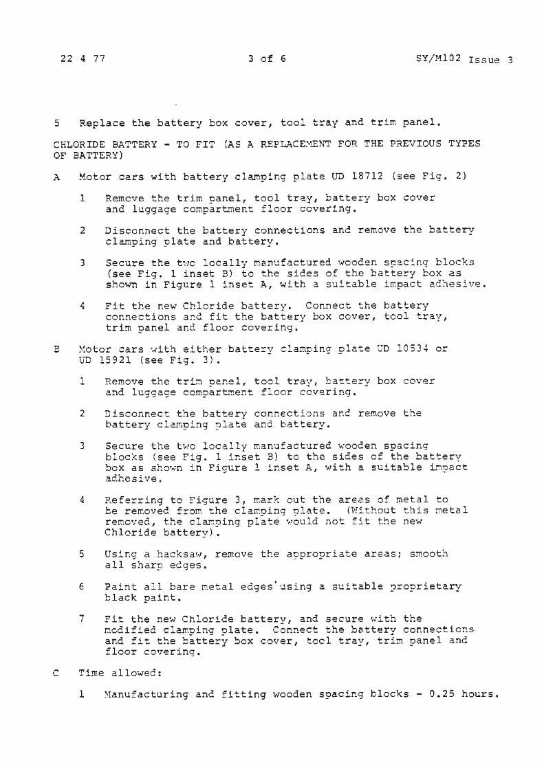
22 4 77 3 of 6 SY/Ml02 Issue 3
5 Replace the battery box cover, tool tray and trim panel.
CHLORIDE BATTERY - TO FIT (AS A REPLACE~1ENT FOR THE PREVIOUS TYPES OF BATTERY)
A Motor cars with battery clamping plate UD 18712 {see Fig. 2)
l Remcve the trim ~anel, tool tray, battery box cover and luggage compartment floor covering.
2 Disconnect the battery connections and remove the battery clamping plate and battery.
3 Secure the t~·rc locally rnanuf actured wooden s~ac::.ng blocks (see Fig. l inset B) to the sides of the battery box as shown in Figure 1 inset A, with a suitable impact adhesive.
4 Fit the new Chloride battery. Connect the battery connections and fit the battery box cover, tool tray, trim panel and floor covering.
B ~fotor cars ·..;ith either battery clamping olate UD 10534 or uD 15921 {see Fig. 3}.
1 Remove the tri~ ~anel, tool tray, battery box cover and luggage compartreent floor covering.
2 Disconnect the battery connections anc remove the battery clarnping ?late and battery.
3 Secure the two locally manufactured wooden spacing blocks (see Fig. 1 inset B) to the sides of the battery box as shown in Ficure l inset A, with a suitable iMcact adhesive. "' -
4 Referring to ;igure 3, mark out the areas of metal to be rereoved from the clamping plate. (Without this metal remc•:ed, the clar::r,>ing pla4=e would not fit the new Chloride battery).
S Using a hacksaw, remove the appropriate areas; smooth all sharp edges.
6 Paint all bare metal edges·using a suitable proprietary black paint.
7 Fit the new Chloride battery, and secure with the ncdified cla~ping plate. Connect the battery connections and fit the battery ~ox cover, tool tray, trim panel and floor covering.
C Time allowed:
1 ~anufacturing and fitting wooden spacing blocks - 0.25 hours.

22 4 77 4 of 6 SY/!1102 Issue 3
2 ~1odif ications to clam.ping plate - 0.5 hours.
Iily/SW
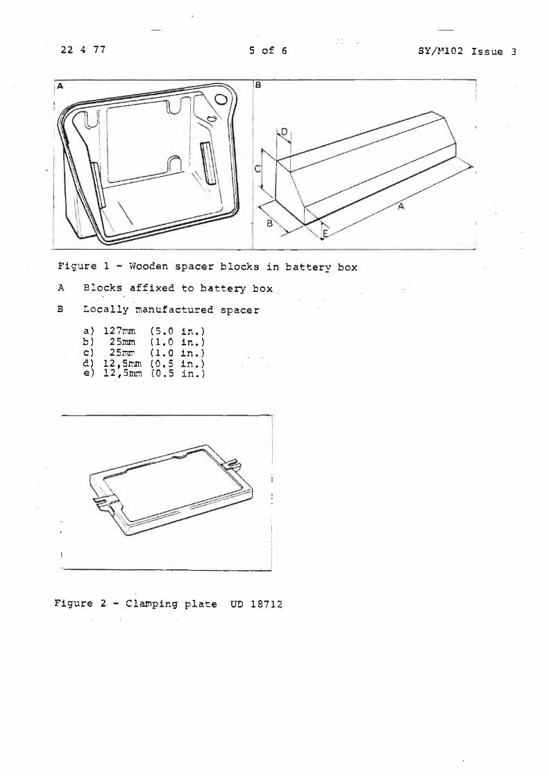
I
I . !
I J
22 4 77 5 of 6
Figure 1 - Wooden spacer blocks in battery box
A Blocks affixed to battery box
B Locally manufactured spacer
a) l27mrr. (5.0 in.) b) 25mm ( 1. 0 in.) c) 25?'!",1'!'1 { l. 0 in.) d) 12, Srr.m (0. 5 in.) e) 12,5mm ( 0. 5 in.)
Figure 2 - Clamping plate UD 18712
SY/Ml02 Issue 3
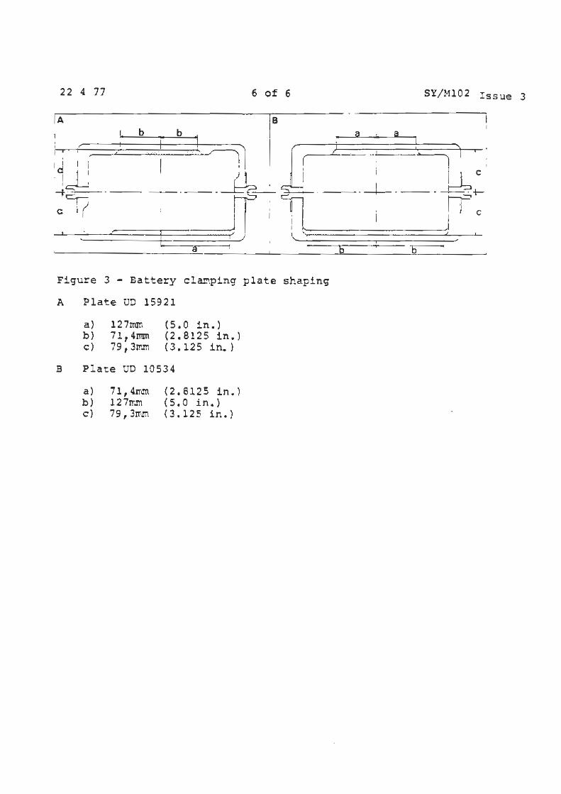
22 4 77
·-t~--'---c I (
I I I \ r
6
b b
..... ..
·-r·- -1 I
a
of 6 SY/ Hl02 I ss ue 3
18 __ 1..,____
( I C
I I
-~ ·---~+-. I '
I I I C
l \ f J I I
- I I ;I
....--~--- ---.-5----;;
Figure 3 - Battery clar.ping plate shaping
A Plate UD 15921
a ) b) c)
127mm 71 1 4mm 79, 3I!'Jt\
( s. 0 in.) (2.8125 in.) (3.125 in.}
B P l ate UD 10 534
a) 71, 4rnm (2. 8125 in.) b) 127~.m (s.o in. ) c) 79,3rrm (3.125 in.)
0 ;
Service Bulletin
I ID>OLLS- l Jf\\OYCE I
I MOTORS I Car Division
TSO 4171
Bl,1:e1:r. nurrber SY/Ml04 (Issue 2} Date 2 11 77 Page l of 6 Crc112.!;on 11st II II I II II II II I I I I I Category C
ALL DISTRIBt"I'ORS AJ.~D RETAILERS
TESTI)TG THE ELECT~ONIC AUTO:t-'f.ATIC SPEED CONTP.OL SYSTE!1
J...PPLICABLE TO:
All Rolls-~oyce Silver Shadow II, Corniche and ca~argue Cars, and all Bentley T2 and Corniche Cars.
I~TROCC'CTION:
T~e following is a test and fault diagnosis sequence to use on the electronic speed control system to dete~ine problems.
In the near future a test box will be available to carry out all checks.
Cl:".SCRI?':'.:'ION:
In the event of a speee control syste~ failure, fuse nurrher 9 should be checked. This fuse supplies power to the speed control system and also to the direction incicators, brake lights, height control solenoid and reversing lights. If the fuse is blown and it continues to blow, then the above circuits must be checked to establish the cause before proceeding further with the speedorr.eter.
P..ssuming that the replacement fuse does not blow, then t!1e soeed-control sys~err. may be road tested for cor rect operation. If it is still inoperative or i £ the fus e was intact initially, then the speedo~eter gene r ator may also be checked.
When the speedoreeter instrument is operating satisfactorilv, it is unlikely that there is a fault in the generator sufficient to cause a complete failure of the speed control. However, any incorrect operation of the speecometer should be rectified and a further road test given before proceeding with the speed control fault diagnosis.
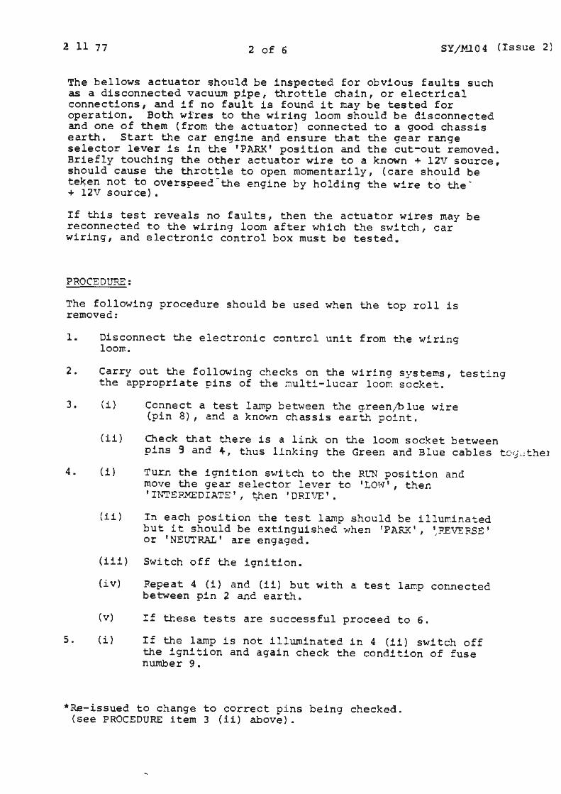
2 11 77 2 of 6 SY/~.J.04 (Issue 2)
The bellows actuator should be inspected for obvious faults such as a disconnected vacuum pipe, throttle chain, or electrical connections, and if no fault is found it may be tested for operation. Both wires to the wiring loom should be disconnected and one of them (from the actuator) connected to a good chassis earth. Start the car engine and ensure that the gear range selector lever is in the 'PAR:K' position and the cut-out removed. Briefly touching the other actuator wire to a known+ 12V source, should cause the throttle to open momentarily, (care should be te~en not to overspeed-the engine by holding the wire to the' + 12V source} •
If this test reveals no faults, then the actuator wires may be reconnected to the wiring loom after which the switch, car wiring, and electronic control box must be tested.
PROCEDURE:
The following procedure should be used when the top roll is removed:
l. Disconnect the electronic control unit from the wiring loom.
2. Carry out the following checks on the wiring syste~s, testing the appropriate pins of the ~ulti-lucar loom socket.
3 .
4.
5.
{i) Connect a test lamp between the g.reen;blue wire (pin 8), and a known chassis earth point.
{ii) Check that there is a link on the loom socket between
(i}
pins 9 and+, thus linking the Green and Blue cables tog~the1
Turn the ignition switch to the RCN position and move the gear selector lever to 'LOW', then I INTEP..MEDIATE t ' 1;hen 'DRIVE' •
(ii) In each position the test lamp should be illuminated but it should be extinguished when 'PAru<: 1 , ',F.EVEF.SE 1
or 'NEUTRAL' are engaged.
(iii) Switch off the ignition.
{iv) P.epeat 4 {1) and (ii) but with a test lamp connected between pin 2 and earth.
(v) !f tr.ese tests are successful proceed to 6.
(i) If the lamp is not illwninated in 4 (11) switch off the ignition and again check the condition of fuse number 9.
*Re-issued to change to correct pins being checked. (see PROCEDURE item 3 (ii) above).
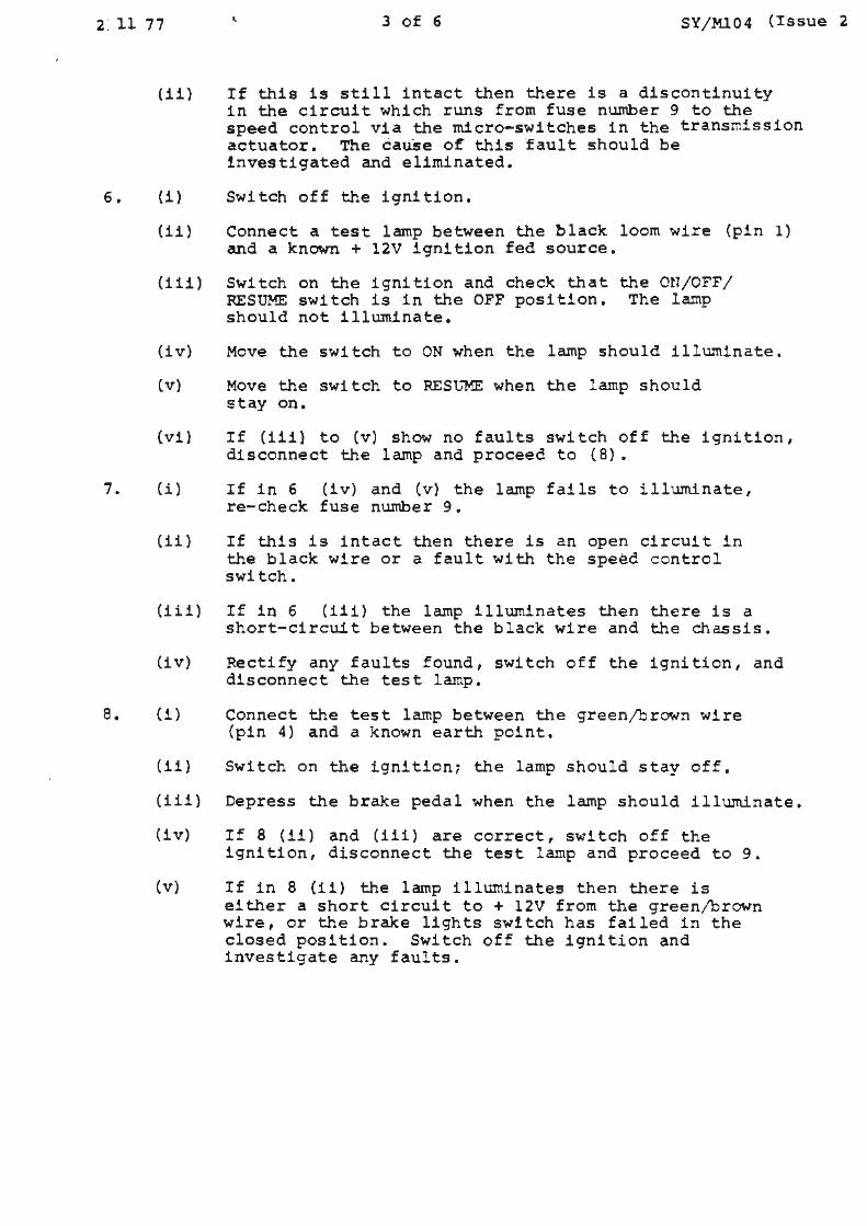
2: ll 77 3 of 6 SY/Ml04 (Issue 2
6.
7.
a.
(11) If this is still intact then there is a discontinuity
(i)
in the circuit which runs from fuse number 9 to the speed control via the micro-switches in the transmission actuator. The cause of this fault should be investigated and eliminated.
Switch off the ignition.
(ii) Connect a test lamp between the black loom wire (pin 1) and a known+ 12V ignition fed source.
{iii) Switch on the ignition and check that the ON/OFF/ RESUME switch is in the OFF position. The lamp should not illuminate.
(iv) Move the switch to ON when the lamp should illuminate.
(v) Move the switch to RESu'"ME when the lamp should stay on.
{vi} If (iii} to (v) show no faults switch off the ignition, disconnect the lamp and proceed to (8).
(i) If in 6 (iv) and (v) the lamp fails to illuminate, re-check fuse number 9.
(ii) If this is intact then there is an open circuit in the black wire or a fault with the speed control switch.
(iii) If in 6 (iii) the lamp illuminates then there is a short-circuit between the black wire and the chassis.
(iv) Rectify any faults found, switch off the ignition, and disconnect the test lamp.
(1) Connect the test lamp between the green/brown wire (pin 4) and a known earth point.
(11) Switch on the ignition; the lamp should stay off,
(iii) Depress the brake pedal when the lamp should illuminate.
(iv) If 8 (11) and (iii) are correct, switch off the ignition, disconnect the test lamp and proceed to 9.
(v) If in 8 (ii) the lamp illwninates then there is either a short circuit to+ 12V from the green/brown wire, or the brake lights switch has failed in the closed position. Switch off the ignition and investigate any faults.
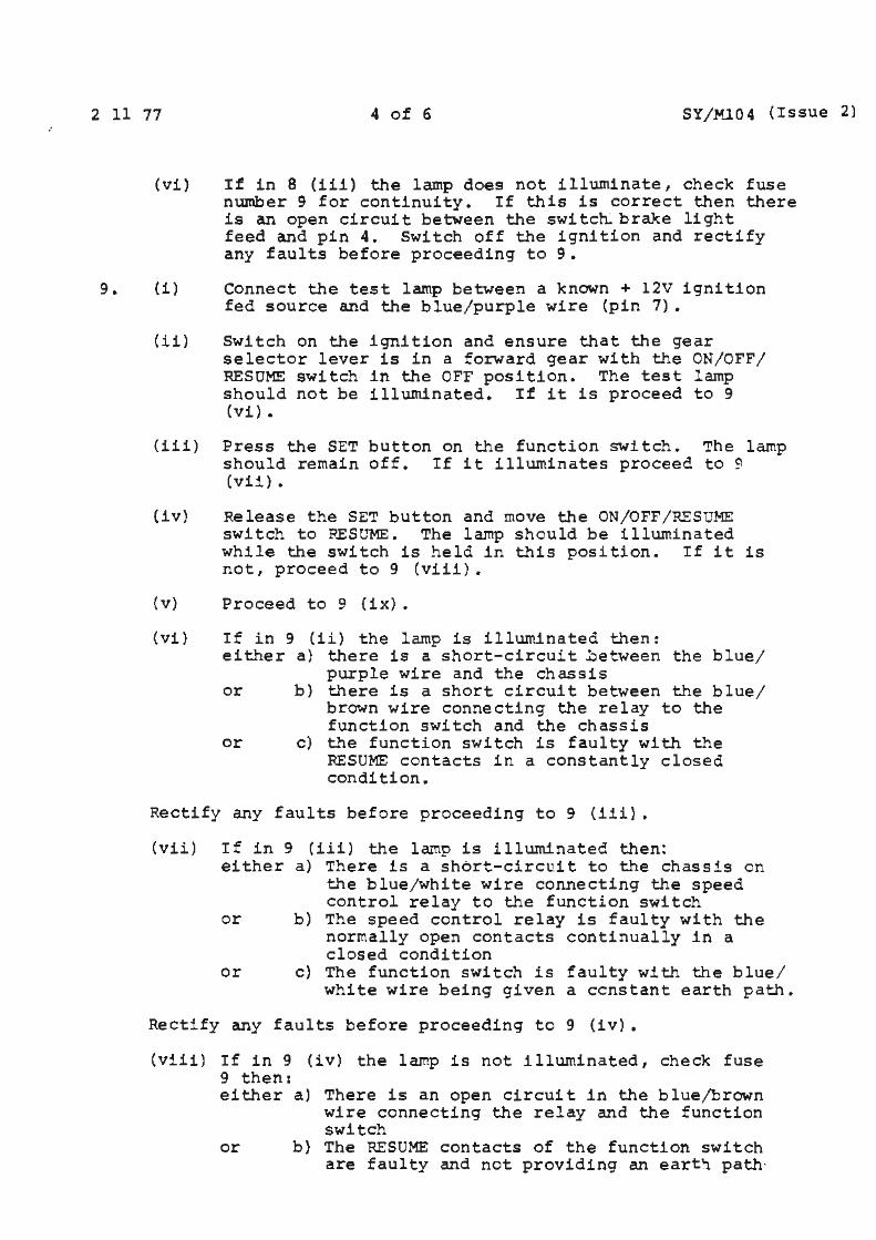
2 11 77 4 of 6 SY/Ml04 (Issue 2)
9.
(vi) If in 8 (111) the lamp does not illuminate, check fuse nUJnber 9 for continuity. If this is correct then there is an open circuit between the switch. brake light
(1)
feed and pin 4. Switch off the ignition and rectify any faults before proceeding to 9.
Connect the test lamp between a known+ 12V ignition fed source and the blue/purple wire (pin 7).
(ii) Switch on the ignition and ensure that the gear selector lever is in a forward gear with the ON/OFF/ RESUME switch in the OFF position. The test lamp should not be illuminated. If it is proceed to 9 (vi) .
(iii) Press the SET button on the function switch. The lamp should remain off. If it illuminates proceec to 9 (vii) •
(iv) Release the SET button and move the ON/OFF/RESUME swi tch to PESUME. The larnp should be illuminated whi l e the switch is held in this pos i tion. If it is not, proceed to 9 (viii).
(v) Proceed to 9 (ix).
(vi) If in 9 (ii) the lamp is illuminated then: either a) there is a short-circuit ~etween the blue/
purple wire and the chassis or b} there is a short circuit between the b l ue/
brown wire connecting the relay to the function switch and the chassis
or c) the function switch is faulty with the RESUME contacts in a constantly closed condition.
Rectify any faults before proceeding to 9 (iii).
(vii) If in 9 (iii) the lamp is illuminated then: either a) There is a short-circuit to the chassis on
the blue/white wire connecting the speed control relay to the function switch
or b) The speed control relay is faulty with the normally open contacts continually in a closed condition
or c) The function switch is faulty with the blue/ white wire being given a constant earth path.
Rectify any faults before proceeding to 9 (iv).
(viii ) If in 9 (iv) the lamp is not illuminated, check fuse 9 then: either a) There is an open circuit in the blue/brown
wire connecting the relay and the function switch
or b) The RESUME contacts of the function switch are faulty and not providing an eart~ path·
2 11 77 5 of 6 SY/Ml04 (Issue 2
Rectify any faults before proceeding to 9 (ix).
{ix) Return the ON/OFF/RESUME switch to the ON position. The lamp should be extinguished. If it remains illuminated then there is a short circuit in the function switch between the ON and RESUME contacts. Rectify
10. (i)
any faults, switch off the ignition, disconnect the test lamp, and proceed to 10.
Connect a test lamp between a +12V ignition fed source and the blue/yellow loom wire {pin 9). Move the ON/OFF/RESUME switch to the OFF position.
(ii} Switch on the ignition. The lamp should not illuminate. If the lamp does illuminate, proceed to 10 (v}.
(iii} Press the SET button on the function switch. This should illuminate the lamp while the switch is held in. If the lamp is not illuminated proceed to 10 (vi).
(iv) Switch off the ignition and disconnect the test lamp. Proceed to 10 (iii}.
(v) If in 10 (ii} the lamp illuminates, then there is a short circuit between the blue/yellow wire and the chassis. Rectify and proceed to 10 (iii}.
(vi) If the lamp is not illuminated in 10 {iii) then:
either a) The normally closed contacts of the speed control relay are faulty (open-circuit}
or b) There is an open-circuit in the blue/yellow wire connecting the control box to the relay.
(vii} Rectify, switch off the ignition, disccnnect the test lamp, and proceed to 11.
11. (i} Disconnect the actu~tor frcm the wiring loom and join together the two loom wires.
{ii) At the electronic box loom socket, connect a test larep between the blue/green wire (pin 6) and a known chassis earth point.
(iii} Check that the gear selector lever is in 'PARK'.
(iv) Switch on the ignition when the lamp should remain off.
{v) Move the gear selector lever to 'DRIVE' when the lamp should illuminate.
{vi} If the lamp does not illuminate then there is an opencircuit in one of the leads connecting the electronic unit to the actuator. This should be investigated and rectified.
(vii} Switch off the ignition and re-connect the actuator to the wiring loom. Disconnect the test lamp.
2 11 77
12. (1)
6 of 6 SY/ Ml04 (Issue 2)
Using an electrical test instrument such as an 1 Avorneter' check the continuity of the red/ green
wire which connects the electronic speedometer to the sceed-control- electronic box (pin 3). (NB It is important that MEGGER and similar generator type instruments are not used for this test). An opencircuit in this wire should be rectified.
13. The above tests have verified the correct operation of the wiring system. If no fault has been found then the electronic control box should be checked by the substitution of a proven unit.
Time allowed - 1.5 hours .
Service Bulletin
Bu!let1n number SY/Ml06
Circulation hst I I 11
Category C
II
TO ALL DISTRIBUTORS AND RETAILERS
Date l 11 77
" II I II
OTTER MOTORGUARO - THERMAL SWITCH (HEADLAMP FLASH)
APPLICABLE TO:
All Rolls-Royce Silver Shadow and Corniche cars, and all Bentley 'T' Series and Corniche cars prior to car serial nu.>nbers SRX 9001 and DRX 9040 .
DESCRIPTrON:
Page
11 I
The 'otter motorguard' thermal cut-out switch (UD 11675) is no longer available.
Therm.al switch RH 9161 is a suitable replacement and is supplied in two kits.
RH 2715 Switch Kit Right-hand drive Cars RH 2716 Switch Kit Left-hand drive Cars
Kits consist of
RH 9161 Switch 1 off RH 9158 Plate 1 off RH 9159/60 Cable 2 off
PROCEDURE OF ASSEMBLY
Refer to Figure 1 - Right-hand drive cars
1. Place the mounting plate (RH 9158) against the left-hand side o f the hinged mounting bracket (UB 15383) as shown in Figure 1 and mark two hqles. Drill the 3.4mm (0.134 in) holes in the mounti!).g bracket.
ID>OLLSrf").\OYCT MOTORS
Car Division
TSD 4171
1 of 3
11 I
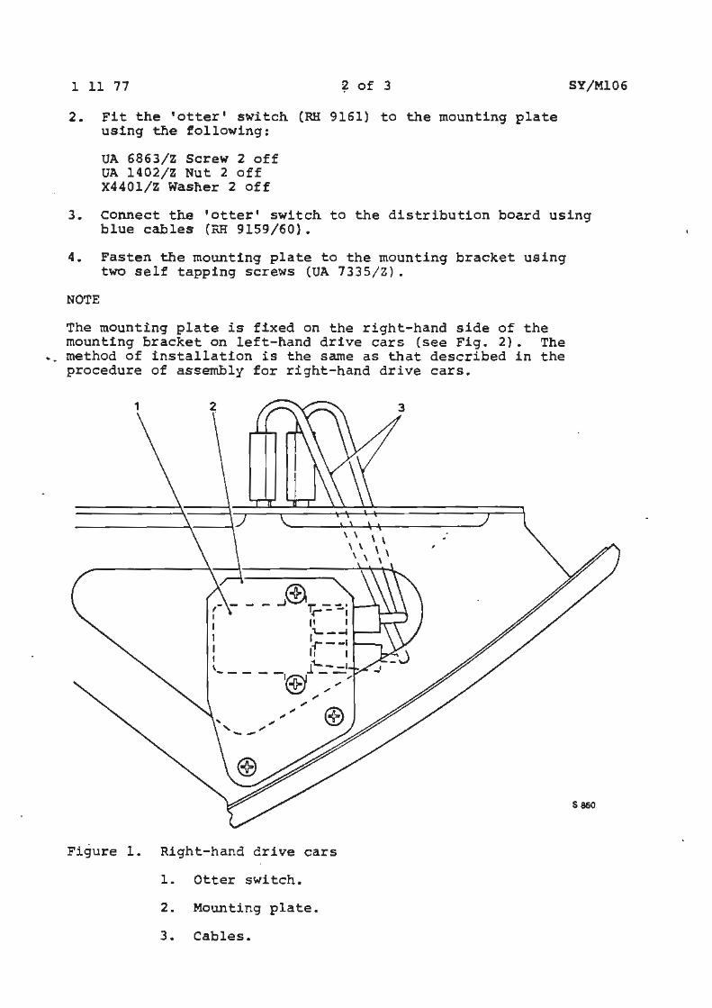
1 11 77 ~ of 3
2. Fit the 'otter' switch (RH 9161) to the mounting plate using the following :
UA 6863/Z screw 2 off UA 1402/Z Nut 2 off X4401/Z Washer 2 off
SY/Ml06
3. connect the 'otter' switch to the distribution board using blue cables (RH 9159/60}.
4. Fasten the mounting plate to the mounting bracket using two self tapping screws (UA 7335/ Z) .
NOTE
The mounting plate is fixed on the right-hand side of the mounting bracket on left-hand drive cars (see Fig. 2}. The method of installation is the same as that described in the procedure of assembly for right-hand drive cars.
- - ..J®~ -- , •r--, 11 I j'- -_. -r--1
I 11 I t \ l~ - -l -- - - -,® ~ :-,.
-- ,,, ....
....
Figure 1. Right-hand drive cars
1. Otter switch.
2. Mounting plate.
3. Cables.
S 860
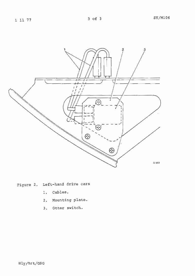
1 11 77 3 of 3 SY/Ml06
Figure 2. Left-hand drive cars
1. Ca.bl es.
2. Mounting plate.
3. Otter switch.
Hly /Brt/GSG
• erv1ce Bulletin
ID)OLLSrf\\OYCE 1\~0TORS
Car Division
.TS D 1.l i7~
3,.,i'E'·'.1r. nur>~ber SY/Ml08 Date 6 l 78 Pa Je 1 of 1
c~·~·,_.:c1ton11st 1 1 11 11 II 11 I 11 II 11 I I
a Category A
ALL FRANCHISE HOLDERS
ELECTRONIC SPEED CONTROL
APPLICABLE TO:
All Rolls-Royce and Bentley motor cars from car serial number 30001.
INTRODUCTION:
It has been determined that a malfunction can occur in the electronic speed control system circuitry resulting in a failure to disengage when the brake pedal is applied.
An engineering solution will be available shortly, but as a temporary measure the chain connecting thespeed control bellows to the throttle linkage must be removed.
A further Service Bulletin will be issued when the permanent engineering solution to correct themalfunction becomes available.
PROCEDURE:
1. Remove the chain connecting the servo bellows to the engine throttles. The chain should be retained by the franchise holder until further notice from the Factory.
2. Complete one of the pink cards supplied (a sample is attached) with the date the work is carried out, the serial number of the car and your own name and address. These cards must be returned as quickly as possible to the Rolls-Royce Motors Warranty Controller, as they provide the basis of the recording system for completion of the campaign. Claims for the cost of completing this work will only be reimbursed on completion and submission of a warranty claim in the normal way.
TIME ALLOWED
To carry out SY/Ml08 - 0.25 hours.
• ~:;erv1ce • e n
SY/Ml09 Issue 2
I I 11 11 11
:.- _; ory B
ALL FRANCHISE HOLDERS
ELECTRONIC SPEED CONTROL MODIFICATION
APPLICABLE TO:
Date 22 5 78 Pag'?
11 11 11
rt))OLLSrf\\OYCE ,,l~OTORS
Car Division
T$C)li71
1 of 24
11
All Rolls-Royce Silver Shadow II, Silver Wraith II, Corniche and Camargue motor cars and all Bentley T2 and Corniche motor cars from car serial number 30001 to 34685 inclusive.
INTRODUCTION:
This Service Bulletin instructs the fitting procedure for a modification to overcome the possibility of a malfunction within the speed control system as outlined in category 1 A 1
Service Bulletin SY/Ml08.
The bulletin describes five different procedures which are required to cover different types of motor cars.
Each group of motor cars is listed at the beginning of each procedure to ease identification of the correct procedure for any motor car.
*Reason for re-issue: To add procedures and car serial numbers not previously included.
22 5 78
DESCRIPTION:
2 of 24 SY/Ml09 Issue 2
Two inhibit circuits have been introduced which operate independently from the main electronic speed control circuit integral inhibit systems.
One is a circuit which de-activates the speed control bellows for as long as the brake pedal is applied; this circuit complements the main speed control brake inhibit and 'resume' circuit.
A second circuit has been introduced which will enable the speed control to operate only when the motor car is in top gear; this is achieved by a switch, within the gearbox, sensing top gear hydraulic pressure.
On receipt of this bulletin the Franchise Holder should inform owners whose cars have had the speed control chain disconnected, as per Service Bulletin SY/Ml08, of the availability of this modification.
Owners should be advised that automatic selection of second gear will render the speed control inoperative, eg a road speed below approximately 40 m.p.h. (60 K.p.h.) on a steep gradient.
PROCEDURE FOR LEFT-HAND DRIVE CARS BUILT TO COMPLY WITH USA, CANADIAN AND JAPANESE REGULATIONS FROM CAR SERIAL NUMBER 30001 UP TO AND INCLUDING:
SBG 33833 LRG 32864 DRG 32556 JRG 32036
Silver Shadow II and Bentley T2 Silver Wraith II Corniche Camargue
Refer to Figures 1 and 2
1 Fit UD 9270 relay provided to the speed control bellows mounting bracket, utilising the 2BA setscrews, washers and nuts provided as shown in Figure 3.
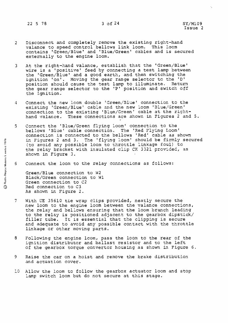
X) ... ~ ,:, .: -.., :n s 3 :::; :, ;.> > 0
X Ji ; C:
©
22 5 78 3 of 24 SY/Ml09 Issue 2
2 Disconnect and completely remove the existing right-hand valance to speed control bellows link loom. This loom contains 'Green/Blue' and 'Blue/Green 1 cables and is secured externally to the engine loom.
3 At the right-hand valance, establish that the 'Green/Blue' wire is a 'positive' feed by connecting a test lamp between the 'Green/Blue' and a good earth, and then switching the ignition 'on'. Moving the gear range selector to the 'D' position should cause the test lamp to illuminate. Return the gear range selector to the 'P' position and switch off the ignition.
4 Connect the new learn double 'Green/Blue' connection to the existing 'Green/Blue' cable and the new loom 'Blue/Green' connection to the existing 'Blue/Green' cable at the righthand valance. These connections are shown in Figures 2 and 5.
5
6
7
Connect the 'Blue/Green flying loom' connection to the bellows 'Blue' cable connection. The 'Red Flying Loom• connection is connected to the bellows 'Red' cable as shown in Figures 2 and 3. The 'flying loom' should be firmly secured (to avoid any possible loom to throttle linkage foul) to the relay bracket with insulated clip CK 3321 provided, as shown in Figure 3.
Connect the loom to the relay connections as follows:
Green/Blue connection to W2 Black/Green connection to Wl Green connection to C2 Red connection to C3 As shown in Figure 2.
With UE 35610 tie wrap clips provided, neatly secure the new lcom to the engine loom between the valance connections, the relay and bellows ensuring that the loom branch leading to the relay is positioned adjacent to the gearbox dipstick/ filler tube. It is essential that the clipping is secure and adequate to avoid any possible contact with the throttle linkage or other moving parts.
8 Following the engine lcom, pass the loom to the rear of the ignition distributor and ballast resistor and to the left of the gear~ox torque converter housing as shown in Figure 6 .
9 Raise the car on a hoist and remove the brake distribution and actuation cover.
10 Allow the loom to follow the gearbox actuator loom and stop lamp switch loom but do not secure at this stage.
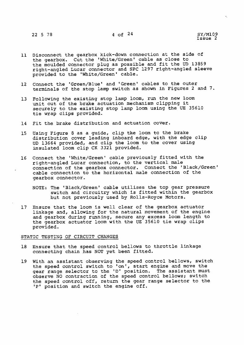
22 S 78 4 of 24 SY/Ml09 Issue 2
11 Disconnect the gearbox kick-down connection at the side of the gearbox. Cut the 'White/Green• cable as close to the moulded connector plug as possible and fit the UD 13859 right-angled Lucar connector and SPC 1297 right-angled sleeve provided to the 'White/Green• cable.
12 connect the 'Green/Blue' and 'Green' cables to the outer terminals of the stop lamp switch as shown in Figures 2 and 7.
13 Following the existing stop lamp loom, run the new loom unit out of the brake actuation mechanism clipping it securely to the existing stop lamp loom using the UE 35610 tie wrap clips provided.
14 Fit the brake distribution and actuation cover.
15 Using Figure 8 as a guide, clip tae loom to the brake distribution cover leading inboard edge, with the edge clip UD 13664 provided, and clip the loom to the cover using insulated loom clip CK 3321 provided.
16 Connect the 'White/Green' cable previously fitted with the right-angled Lucar connection, to the vertical male connection of the gearbox connector. Connect the 'Black/Green' cable connection to the horizontal male connection of the gearbox connector.
NOTE: The 'Black/Green• cable utilises the top gear pressure switch and circuitry which is fitted within the gearbox but not previously used by Rolls-Royce Motors.
17 Ensure that the loom is well clear of the gearbox actuator linkage and, allowing for the natural movement of the engine and gearbox during running, secure any excess loom length to the gearbox actuator loom with the UE 35610 tie wrap clips provided.
STATIC TESTING OF CIRCUIT CHANGES
18 Ensure that the speed control bellows to throttle linkage connecting chain _has NOT yet been fitted.
19 With an assistant observing the speed control bellows, switch the speed control switch to 'onr, start engine and move the gear range selector to the 1 0• position. The assistant must observe NO contraction of the speed control bellows; switch the speed control off, return the gear range selector to the 'P' position and switch the engine off.
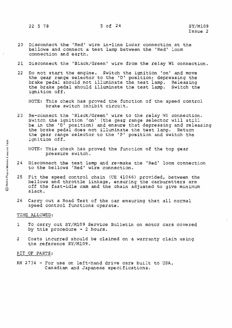
,,
22 5 78 5 of 24 SY/Ml09 Issue 2
20 Disconnect the 1 Red 1 wire in-line Lucar connection at the bellows and connect a test lamp between the ' Red' loom connection and earth.
21 Disconnect the 'Black/ Green' wire from the relay Wl connection.
22 Do not start the engine. Switch the ignition 'on' and move the gear range selector to the 'D' position; depressing the brake pedal should not illuminate the test lamp. Releasing the brake pedal should illuminate the test lamp. Switch the ignition off.
NOTE: This check has proved the function of the speed control brake switch inhibit circu i t.
23 Re-ccnnect the 'Black/Green' wire to the relay Wl connection. Switch the ignition 'on 1 (the gea~ range selector will still be in the 'D' position) and ensure that depressing and releasing the brake pedal does not illuminate the test lamp. Return the gear range·selector to the 'P' position and switch the ignition off.
NOTE: This check has proved the function of the top gear pressure switch.
; 24 Di sconnect the test lamp and re-make the 'Red' loom connection i to the bellows 'Red' wire connection.
©
25 Fit the speed control chain (UE 41066) provided, between the bellows and throttle linkage, ensuring the carburetters are off the fast-idle cam and the chain adjusted to give minimum slack.
26 Carry out a Road Test o f the car ensuring that all normal speed control functions operate.
TIHE ALLOWED:
1 To carry out SY/Ml09 Service Bulletin on motor cars covered by this procedure - 2 hours.
2 Costs incurred should be claimed on a warranty claim using the reference SY/Ml09.
KIT OF PARTS:
RE 2734 - For use on left-hand drive cars built to USA, Canadian and Japanese specifications.
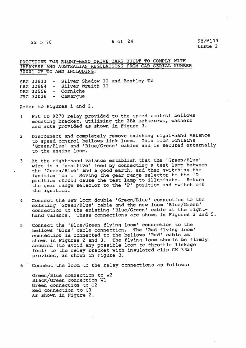
.. 22 5 78 6 of 24
PROCEDURE FOR RIGHT-HAND DRIVE CARS BUILT TO COMPLY WITH JAPANESE ANO AUSTRALIAN REGULATIONS FROM CAR SERIAL NUMBER 30001 UP TO ANO INCLUDING:
SBG 33833 LRG 32864 DRG 32556 JRG 32036
Silver Shadow II and Bentley T2 Silver Wraith II Corniche Camargue
Refer to Figures 1 and 2.
1 Fit UD 9270 relay provided to the speed control bellows mounting bracket, utilising the 2BA setscrews, washers and nuts provided as shown in Figure 3.
SY/Ml09 Issue 2
2 Disconnect and completely remove existing right-hand valance to speed control bello~s link loom. This loom contains 'Green/Blue• and 'Blue/Green' cables and is secured externally to the engine loom.
3 At the right-hand valance establish that the 'Green/Blue' wire is a 'positivet feed by connecting a test lamp between the 'Green/Blue' and a good earth, and then switching the ignition 'on'. Moving the gear range selector to the 'D 1
position should cause the test lamp to illuminate. Return the gear range selector to the 'P' position and switch off the ignition.
4 Connect the new lcom double 'Green/Blue' connection to the existing 'Green/Blue' cable and the new loom 'Blue/Green' connection to the existing 'Blue/Green' cable at the righthand valance. These connections are shown in Figures 2 and 5.
5 Connect the 'Blue/Green flying loom' connection to the bellows 'Blue' cable connection. The 'Red flying loom' connection is connected to the bellows 'Red' cable as shown in Figures 2 and 3. The flying loom should be firmly secured (to avoid any possible loom to throttle linkage foul) to the relay bracket with insulated clip CK 3321 provided, as shown in Figure 3.
6 Connect the loom to the relay connections as follows:
Green/Blue connection to W2 Black/Green connection Wl Green connection to C2 Red connection to C3 As shown in Figure 2.

22 5 78 7 of 24
7 With the UE 35610 tie wrap clips provided neatly secure
SY/Ml09 Issue 2
the new loom to the engine loom between the valance connections, the relay and bellows ensuring that the loom branch leading to the relay is positioned adjacent to the gearbox dipstick/filler tube. It is essential that the clipping is secure and adequate to avoid any possible contact with the throttle linkage or other moving parts.
a Raise the car on a hoist and remove the brake distribution and actuation cover.
9 Pass the loom containing the· 'Green' and 'Green/Blue' cables down towards the brake actuation. and distribution mechanism routing the loom between the hydraulic pipes and the body longeron. Pass the loom under the bridge formed by the bracket which supports the hydraulic pipe junction block. Pass the loom into the brake mechg.nism along with the existing stop lamp loom.
10 Pass the single sleeved 1 Black/Green 1 wire to the rear of the ignition distributor and ballast resistor and to the left of the gearbox torque converter housing; allow the loom to lie on the gearbox housing.
11 Disconnect the gearbox kickdown connection at the side of the gearbox. Cut the 'White/Green' cable as close to the moulded connector plug as possible and fit the UD 13859 rightangled Lucar connector and SPC 1297 right-angled sleeve provided to the 1 White/Greent cable.
12 Connect the 'Green/Blue' and 'Green' cables to the outer terminals of the stop lamp switch as shown in Figures 2 and 7.
13 Fit the brake distribution and actuation cover.
14 Connect the 'White/Green' cable previously fitted with the right-angled Lucar connector to the vertical male connection of the gearbox connector. Connect the 'Black/Green' cable connection to the horizontal male connection of the gearbox connector.
NOTE: The 'Black/Green' cable utilises the top gear pressure switch and circuitry which is fitted within the gearbox but not previously used by Rolls-Royce Motors.
15 Ensure that the loom is well clear of the gearbox actuator linkage and secure any excess loom length to the actuator loom with the UE 35610 tie wrap clips provided .
•
22 5 78 8 of 24
STATIC TESTING OF CIRCUIT CHANGES
SY/Ml09 Issue 2
16 Ensure that the speed control bellows to throttle linkage chain has NOT yet been fitted.
17 With an assistant observing the speed control bellows, switch the speed control switch to 'on', start the engine and move the gear range selector to the 'D' position. The assistant must observe NO contraction of the speed control bellows~ switch the speed control off, return the gear range selector to the 'P' position and switch the engine off.
18 Disconnect the 'Red' wire in-line Lucar connection at the bellows and connect a test lamp between the 'Red' loom wire and earth.
19 Disconnect the 'Black/Green' wire·from the relay Wl connection.
20 Do not start the engine. Switch the ignition 'on' and move the gear range selector to the 'D' position; depressing the brake pedal should not illuminate the test lamp. Releasing the brake pedal should illuminate the test lamp. Switch the ignition off.
NOTE: This check has proved the function of the speed control brake switch inhibit circuit.
21 Re-connect the 'Black/Green• wire to the relay Wl connection. Switch the ignition 'on' (the gear range selector will still be in the 'D' position) and ensure that depressing and releasing the brake pedal does not illuminate the test lamp. Return the gear range selector to the 'P' position and switch the ignition off.
NOTE: This check has proved the function of the top gear pressure switch.
22 Disconnect the test lamp and re-make the 'Red' loom wire to the bellows 'Red' wire connection.
23 Fit the speed control chain (UE 41066} provided between the bellows and throttle linkage, ensuring the carburetters are off the fast-idle cam and the chain adjusted to give minimum slack.
24 Carry out a Road Test of the car ensuring that all normal speed control functions operate.
•
)
22 5 78 9 of 24
TIME ALLOWED:
1 To carry out SY/Ml09 Service Bulletin on motor cars covered by this procedure - 2 hours.
SY/Ml09 Issue 2
2 Costs incurred should be claimed on a warranty claim using the reference SY/Ml09.
KIT OF PARTS:
RH 2738 - For use on right-hand drive cars built to Australian and Japanese specifications.
PROCEDURE FOR LEFT-HAND DRIVE CARS OTHER THAN THOSE BUILT TO COMPLY WITH USA, CANADIAN AND JAPANESE REGULATIONS FROM CAR SERIAL NUMBER 30001 UP TO AND I NCLUDING :
SRH 33863 LRX 33017 DRH 32491 JRH 31962
- Silver Shadow II and Bentley T2 - Silver Wraith II
Corniche - Camargue
a · Refer to Figures land 2 ~
Fit UD 9270 relay provided to the speed control bellows mounting bracket utilising the 2BA setscrews, washers and nuts provided as shown in Figure 3.
NOTE: For Corniche and Carnargue cars fit the UD 9270 relay to the right-hand inner wing as shown in Figure 4, utilising the self-tapping screws and washers provided.
2 Disconnect and completely remove the existing right-hand valance to speed control bellows link loom. This loom contains 'Green/Blue' and 'Blue/Green' cables and is secured externally ta the engine loom.
3 At the right-hand valance establish that the 'Green/Blue' wire is a 'positive' feed by connecting a test lamp between t~e 'Green/ Blue' and a good earth, and then switching the ignition 'on'. Moving the gear range selector to the 'D' position should cause the test lamp to illuminate. Return the gear range selector ·to the 'P' position and switch off the ignition.
22 5 78 10 of 24 SY/Ml09 Issue 2
4 Connect the new loom double 'Green/Blue• connection to the existing 'Green/Blue' cable and the new loom 'Blue/Green' connection to the existing 'Blue/Green• cable at the righthand valance. These connections are shown in Figures 2 and 5.
5 Connect the 'Blue/Green flying loom' connection to the bellows 'Blue' cable connection. The 'Red flying loom' connection is connected to the bellows 'Red 1 cable as shown in Figures 2 and 3. The flying loom should be firmly secured (to avoid any possible loom to throttle linkage foul) to the relay bracket with insulated clip CK 3321 as shown in Figure 3.
6 connect the loom to the relay connections as follows:
Green/Blue connection to W2 Black/Green connection to Wl Green connection to C2 Red connection to C3 As shown in Figure 2.
7 With UE 35610 tie wrap clips provided neatly secure the
8
new loom to the engine loom between the valance connections, the relay and bellows ensuring that the loom branch leading to the relay is positioned adjacent to the gearbox dipstick/ filler tube. It is essential that the clipping is secure and adequate to avoid any possible contact with the throttle linkage or other moving parts.
NOTE: For Corniche and Camargue cars the loom branch to the relay positioning does not apply due to the relay location difference.
Following the engine loom, pass the loom to the rear of the ignition distributor and ballast resistor and to the left of the gearbox torque converter housing as shown in Figure 6.
9 Raise the car on a hoist and remove the brake distribution and actuation cover.
10 Allow the loom to follow the gearbox actuator loom and stop lamp switch loom but do not secure at this stage.
11 Disconnect . the gearbox kick-down connection at the side of the gearbox. Cut the 'White/Green' cable as close to the moulded connector plug as possible and fit the UD 13859 right-angled Lucar connector and SPC 1297 right-angled sleeve provided to the 'White/Green' cable.
@
22 5 78 11 of 24 SY/Ml09 Issue 2
12 Connect the 'Green/Blue' and 'Green' cables to the outer terminals of the stop lamp switch as shown in Figures 2 and 7.
13 Following the existing stop lamp loom run the new loom out of the brake actuation mechanism clipping it securely to the existing stop lamp loom using the UE 35610 tie wrap clips provided.
14 Fit the brake distribution and actuation cover.
15 Using Figure 8 as a guide, clip the loom to the brake distribution cover leading inboard edge, with the edge clip UD 13664 provided, and clip the loom to the cover using insulated loom clip CK 3321 provided.
16 Drain the gearbox fluid and remove the gearbox sump and filter as described in Chapter T - Part 2, of Work shop Manual T.S.D. 2476.
17 Remove the pressure switch blankih~ plug shown in Figure 9 and screw in the top gear pressure switch GM 6462286 supplied.
NOTE: Threads on top gear pressure switch are tapered (torque tighten to 6 to 10 lbf. ft.).
18 Remove the existing gearbox connector by squeezing inwards the three locating legs and pushing the connector out of the gearbox casing. Fit the new connector GM 8626579 and 'O' ring G.~ 8619568 supplied.
19 Connect the top gear pressure switch to the connector block lead GM 8626426 supplied, between the switch and the large Lucar blade of the connector block . This lead must be routed as shown in Figure 10.
20 Ensure the kick-down solenoid connection has been reconnected to the small Lucar blade of the connector block.
21 Fit the filter and sump, using sump gasket supplied, as described in Chapter T - Part 2, of Workshop Manual T.S.D. 2476.
22 Connect the 'White/ Green' cable previously fitted with the r ight-angled Lucar connector to the vertical male connection of the gearbox connector. Connect the 'Black/Green' cable connection to the horizontal male connection of the gearbox connector.
23 Ensure that the loom is well clear of the gearbox actuator linkage, and allowing for the natural movement of the engine and gearbox during running secure any ex:::ess loom length to the gearbox actuator loom with the UE 35610 tie wrap clips provided.
22 5 78 12 of 24
STATIC TESTING OF CIRCUIT CHANGES
SY/Ml09 Issue 2
24 Ensure that the speed control bellows to throttle linkage connecting chain has NOT yet been fitted.
25 With an assistant observing the speed control bellows, switch the speed control switch to 'on•, start engine and move the gear range selector to the •o• position. The assistant must observe NO contraction of the speed control bellows; switch the speed control off, return the gear range selector to the 'P' position and switch the engine off.
26 Disconnect the 'Red' wire in-line Lucar connection at the bellows and connect a test lamp between the 'Red' loom connection and earth.
27 Disconnect the 'Black/Green• wire from the Wl connection of the relay.
28 Do not start the engine. Switch the ignition 'on' and move the gear range selector to th~ 'D' position; depressing the brake pedal should not illuminate the test lamp. Releasing the brake pedal should illuminate the test lamp. Switch the ignition off.
NOTE: This check has proved the function of the speed control brake switch inhibit circuit.
29 Re-connect the 'Black/Green' wire to the relay WI connection. Switch the ignition •ont (the gear range selector will still be in the 'D' position) and ensure that depressing and releasing the brake pedal does not illuminate the test lamp. Return the gear range selector to the 'P 1 position and switch the ignition off.
NOTE: This check has proved the fwiction of the top gear pressure switch.
30 Disconnect the test lamp and re-make the 'Red' loom connection to the bellows 'Red' wire connection.
31 Fit the speed control chain (UE 41066) provided, between the bellows and throttle linkage, ensuring the carburetters are off the fast-idle cam and the chain adjusted to give minimum slack.
NOTE: Cars fitted with Solex carburetters have speed control chain UE 36757 and chain sleeve UE 36551 fitted.
32 carry out a Road Test of the car ensuring that all normal speed control fwictions operate.
TIME ALLOWED:
l To carry out SY/Ml09 Service Bulletin on motor cars covered by this procedure - i.as hours.
~ ~
~
i -~ ~ 0 3 ~ ~ u ~
~ ~ ~
~-
©
22 5 78 13 of 24 SY/ Ml09 Issue 2
. 2 Costs incurred should be claimed on a warranty claim using the reference SY/Ml09.
KIT OF PAR~S:
RH 2746 - for use on left-hand drive cars fitted with SU carburetters.
RH 2748 - for use on left-hand drive cars fitted with Solex carburetters.·
PROCEDURE FOR RIGHT-HAND DRIVE CARS OTHER THAN THOSE BUI LT TO COMPLY WITH J APANESE AND AUSTRALI AN REGULATIONS FROM CAR SERIAL NUMBER 3000 1 UP TO AND INCLUDING :
SRH 33863 - Silver Shadow II and Bentley T2 LRX 33017 - S i l v er Wraith II DRH 32491 - corniche JRH 31962 - Camargue
Refer to Figures 1 and 2
1
2
3
Fit UD 9270 re l a y p r ovi ded to t h e speed control bello ws mounting bracket, utilising the 2BA setscre ws, washers and nuts provided, as shovlI'l in Figure 3.
NOTE : For Corniche and Camargue cars fit the UO 927 0 relay to the right-hand inner wing as sho wn in Figure 4 utilisin g the self-tappin g screws and washers prov i ded.
Disconnect and complete ly r emove t he exi sti ng righ t-hand valance to the s pe ed control bellows link loom. This loom c on t ain s 'Gr een /Blue' and ' Blue/Green' cab l es and is secure d exte rnally to the engine l o o m.
At the r ight- han d val ance , e stablish that the ' Gr een/ Blue ' wire is a ' positive ' feed by connecting a test lamp between t he ' Green/Blue ' and a good earth, and then switching the ignition ' on ' . Movi ng the gear r ange selector to the ' D ' position should caus e t he test lamp t o illumi n ate. Return the gear range s elector to the 'P' position and swi t ch o ff the ignition.
4 Connect the new loom double 'Green/ Blue ' connection to the exi st i n g 'Green/ Blue' cable a nd the new loom ' Blue/Gr een ' connection to the existing 'B lue/Gr e e n cable at the right- hand valance. These connecti ons a re s hown in Figures 2 and~ .
3 Connect the ' Blue/Gr een' flying loom' conne ction to the bellows 'Blue ' cable conne c ti on . The 'Red flying loom ' connection is con n e cted to the bellows ' Red ' c able a s shown in Figures 2 and 3 . The flying loom should be firmly s ecur ed ( to avoid any possibl e loom to throt tle linkage foul ) to the relay brackec ~ith insulated clip CK 3321 p r ovide d, as s hown in Figure 3.
22 5 78 14 of 24 SY/Ml09
6 Connect the loom to the relay connections as follows:
Green/Blue connection to W2 Black/Green connection to Wl Green connection to C2 Red connection to C3 As shown in Figure 2.
Issue 2
7 With the UE 35610 tie wrap clips provided neatly secure the new loom to the engine loom between the valance connections, the relay and bellows. It is essential that the clipping is secure and adequate to avoid any possible contact with the throttle linkage or other moving parts.
NOTE: On motor cars fitted with SU type carburetters ensure that the loom branch leading to the relay is positioned adjacent to the gearbox dipstick/filler tube.
8 Raise the car on a hoist and remove the brake distribution and actuation cover.
9 Pass the loom containing the 'Green• and 'Green/Blue' cables down towards the brake actuation and distribution mechanism routing the loom between the hydraulic pipes and the body longeron. Pass the loom under the bridge formed by the bracket which supports the hydraulic pipe junction block. Pass the loom into the brake mechanism along with the existing stop lamp loom.
10 Pass the single sleeved 'Black/Green' wire to the rear of the ignition distributor and ballast resistor and to the left of the gearbox torque converter housing; allow the loom to lie on gearbox housing.
11 Disconnect the gearbox kick-down connection at the side of the gearbox. Cut the 'White/Green' cable as close to the moulded connector plug as possible and fit the UD 13859 right-angled Lucar connector and SPC 1297 right-angled sleeve provided to the 'White/Green' cable.
12 Connect the 'Green/Blue' and 'Green• cables to the outer terminals of the stop lamp switch as shown in Figures 2 and 7.
13 Fit the brake distribution and actuator cover.
14 Drain the gearbox fluid and remove the gearbox sump and filter as described in Chapter T - Part 2 of Workshop Manual T.s.o. 2476.
15 Remove the pressure switch blanking plug shown in Figure 9 and screw in the top gear pressure switch GM 6462286 supplied.
NOTE; Threads on top gear pressure switch are tapered (torque tighten to 6 to 10 lbf.ft.).
~
~
5
22 5 78 15 of 24 SY/Ml09 Issue 2
16 Remove the existing gearbox connector by squeezing inwards the three locating legs and pushing the connector out of the gearbox casing. Fit the new connector GM 8626597 and 1 0 1 ring GM 8619568 supplied.
17 conne~t the top gear pressure switch to connector block lead GM 8626426 supplied between the switch and the large Lucar blade of the connector block. This lead must be routed as shown in Figure 10.
18 Ensure the kick-down solenoid connection has been reconnected to the small Lucar blade of the connector block.
19 Fit the filter and sump, using sump gasket supplied, as described in Chapter T - Part 2 of Workshop Manual T.S.D. 2476.
20 Connect the 'White/Green' cable previously :itted with the right-angled Lucar connector to the vertical male connection of the gearbox connector. Conne~t the Black/ Green cable connection to the horizontal male-connection of the gearbox connector.
21 Ensure that the loom is well clear of the gearbox actuator linkage, and allowing for the natural ~overnent of the engine and gearbox during running, secure any excess loom length to the gearbox actuator loom with the UE 35610 tie wrap clips provided.
~ STATIC TESTING OF CIRCUIT CHANGES ~ ~
$ 22 Ensure that the speed control bellows to throttle linkage 1 connecting chain has NOT yet been fitted. 0 ~
© 23 With an assistant observing the speed control bellows, switch the speed control switch to 'on', start the engine and move the gear range selector to the 1 0 1 position. The assistant must observe NO contraction of the speed control bellows; switch the speed control off, return the gear range selector to the 'P' position and switch the engine off .
24 Disconnect the 'Red' wire in-line Lucar connection at the bellows and connect a test lamp between the 'Red' loom connection and earth.
25 Disconnect the 'Black/Green' wire from the Wl connection of the relay.
26 Do not start the engine. Switch the ignition 'on' and move the gear range selector to the 'D' position; depressing the brake pedal should not illuminate the test lamp. Releasing the brake pedal s hould i l luminate the test lamp. Switch the ignition off.
NOTE: This check has proved the function of the speed control brake switch inhibit circuit.
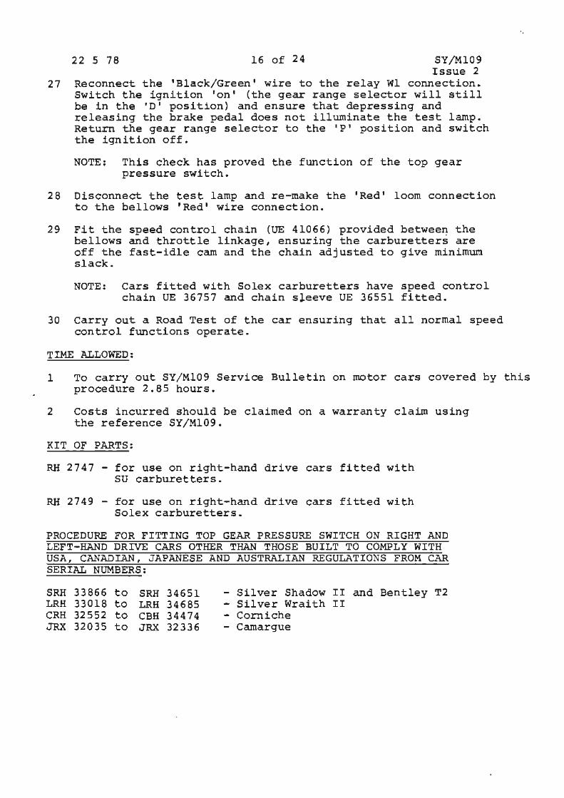
22 5 78 16 of 24 SY/Ml09 Issue 2
27 Reconnect the 'Black/Green• wire to the relay Wl connection. Switch the ignition ton• (the gear range selector will still be in the 'D' position) and ensure that depressing and releasing the brake pedal does not illuminate the test lamp. Return the gear range selector to the 1 P 1 position and switch the ignition off.
NOTE: This check has proved the function of the top gear pressure switch.
28 Disconnect the test lamp and re-make the 'Redt loom connection to the bellows 'Red' wire connection.
29 Fit the speed control chain (UE 41066) provided betwee~ the bellows and throttle linkage, ensuring the carburetters are off the fast-idle cam and the chain adjusted to give minimum slack.
NOTE: Cars fitted with Solex carburetters have speed control ) chain OE 36757 and chain sleeve UE 36551 fitted.
30 Carry out a Road Test of the car ensuring that all normal speed control functions operate.
TIME ALLOWED:
1 To carry out SY/Ml09 Service Bulletin on motor cars covered by this procedure 2.85 hours.
2 Costs incurred should be claimed on a warranty claim using the reference SY/Ml09.
KIT OF PARTS:
RH 2747 - for use on right-hand drive cars fitted with SU carburetters.
RH 2749 - for use on right-hand drive cars fitted with Solex carburetters.
PROCEDURE FOR FITTING TOP GEAR PRESSURE SWITCH ON RIGHT AND LEFT-HAND DRIVE CARS OTHER THAN THOSE BUILT TO COMPLY WITH USA, CANADIAN , JAPANESE AND AUSTRALIAN REGULATIONS FROM CAR SERIAL NUMBERS:
SRH 33866 to SRH 34651 LRH 33018 to LRH 34685 CRH 32552 to CBH 34474 JRX 32035 to JRX 32336
- Silver Shadow II and Bentley T2 - Silver Wraith II - Corniche - Camargue
\
\
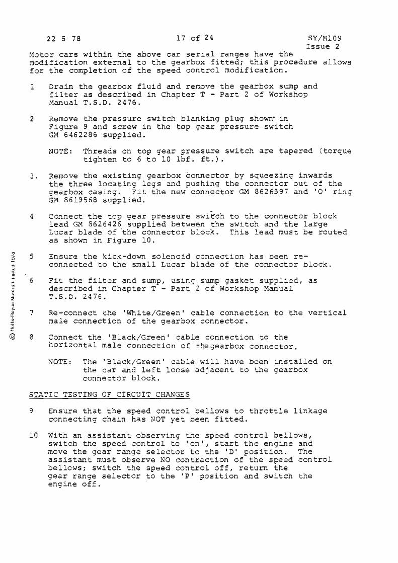
@
22 5 78 17 of 24 SY/Ml09 Issue 2
Motor cars within the above car serial ranges have the modification external to the gearbox fitted; this procedure allows for the completion of the speed control modification.
1 Drain the gearbox fluid and remove the gearbox sump and filter as described in Chapter T - Part 2 of Workshop Manual T.S.D. 2476.
2 Remove the pressure switch blanking plug shown· in Figure 9 and screw in the top gear pressure switch GM 6462286 supplied.
NOTE: Threads on top gear pressure switch are tapered (torque tighten to 6 to 10 lbf. ft.).
3. Remove the existing gearbox connector by squeezing inwards
4
5
6
7
8
the three locating legs and pushing the connector out o f the gearbox casing. Fit the new connect or GM 862659i and 'O' ri~g GM 8619568 supplied.
connect the top gear pressure switch lead GM 8626426 supplied between the Lucar blade of 'the connector block. as shown in Figure 10.
to the connector block switch and the large This lead must be routed
Ensure the kick - down solenoid ccnnection has been reconnected to the small Lucar blade of the connector block.
Fit the filter and sump, using sump gasket s upplied , as described in Chapter T - Part 2 of Workshop Manual T.S.D. 2476.
Re-connect the 'White/ Green' cable connection to the vertical male connection of the gearbox connector.
Connect t he 'B lack/Green ' cable connection to the horizontal male connection of the gearbox co nnec tor.
NOTE: The 'B l ack/ Gre en' cable will have been in s talled on the car and left loose adjacent to the gearbox connector block.
STATIC TESTING OF CIRCUIT CHANGES
9 Ensure that the speed control bellows to throttle linkage connecting chain has NOT yet been fitted.
10 With an assistant observing the speed control bellows, switch the speed control to 'on', s tart the engine and move the gear range selector to the 'D' position. The assistant must observe NO contraction of the speed control bellows; switch the speed control off, return the gear range selector to the 'P' position and switch the engine off.
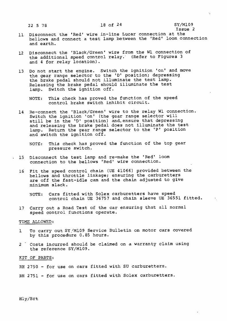
11
22 5 78 18 of 24
Disconnect the 'Red' wire in-line Lucar bellows and connect a test lamp between and earth.
SY/Ml09 Issue 2
connection at the the 'Red' loom connection
12 Disconnect the 'Black/Green• wire from the Wl connection of the additional speed control relay.· (Refer to Figures 3 and 4 for relay location).
13 Do not start the engine. Switch the ignition 'on' and move the gear range selector to the 'D' position·; depressing the brake pedal should not illuminate the test lamp. Releasing the brake pedal should illuminate the test lamp. Switch the ignition off.
NOTE: This check has proved the function of the speed control brake switch inhibit circuit.
14 Re-connect the 'Black/Green' wire to the relay Wl connection. Switch the ignition 'on' (the gear range selector will still be in the 'D' position) and.ensure that depressing and releasing the brake pedal does not illuminate the test lamp. Return the gear range selector to the 'P' position and switch the ignition off.
NOTE: This check has proved the function of the top gear pressure switch.
15 Disconnect the test lamp and re-make the 1 Red 1 loom connection to the bellows 'Red' wire connection.
16 Fit the speed control chain (UE 41066) provided between the bellows and throttle linkage; ensuring the carburetters are off the fast-idle cam and the chain adjusted to give minimum slack.
NOTE: Cars fitted with Solex carburetters have speed control chain UE 36757 and chain sleeve UE 36551 fitted. · ,
17 Carry out a Road Test of the car ensuring that all normal speed control functions operate.
TIME ALLOWED:
1 To carry out SY /Ml09 Service Bulletin on motor cars covered by this procedure 0.85 hours.
2 · Costs incurred should be claimed on a warranty claim using the reference SY/Ml09.
KIT OF PARTS:
RH 2750 - for use on cars fitted with SU carburetters.
RH 2751 - for use on cars fitted with Solex carburetters.
Hly/Brt
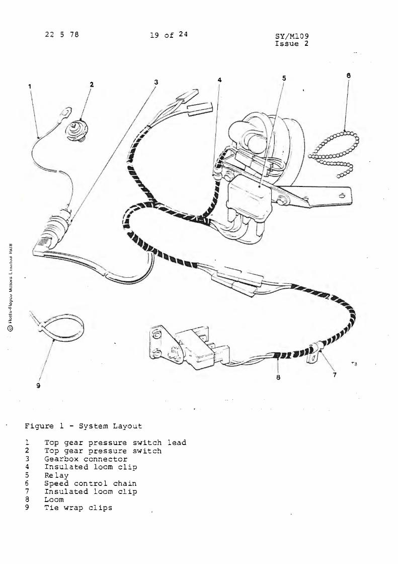
5
®
22 S 78 19 of 24
1
9
System Layout Figure l -
l 2 3 4 5 6 7 8 9
essure switch Top gear pressure switch Top gear pr tor Gearbox cdo~~~~ clip Insulate
Relay trol chain Speed co~ loom clip Insulate Loom
1.
5 Tie wrap c ip
lead
SY/Ml09 Issue 2
5 6
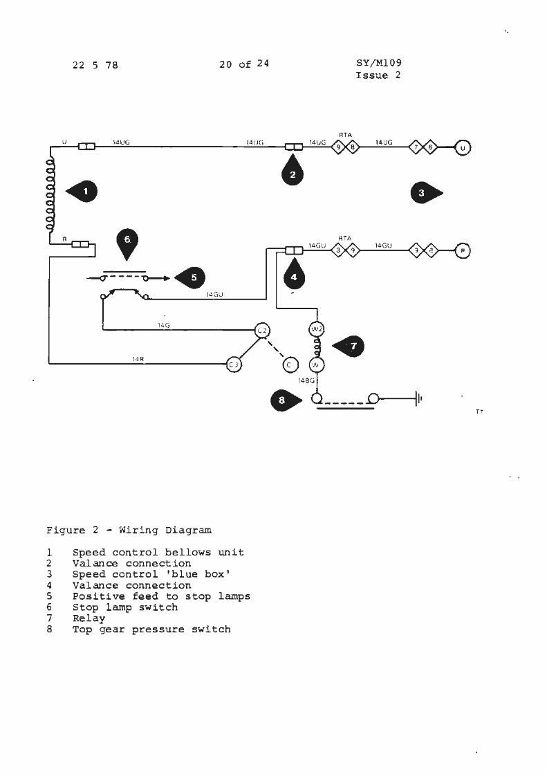
22 S 78 20 of 24
u 14UG
• R
' --c---~-'0-+. 14GU
1-lG
lJR
Figure 2 - Wiring Diagram
l Speed control bellows unit 2 Valance connection 3 Speed control 'blue box' 4 Valance connection
14 UG
5 Positive feed to stop lamps 6 Stop lamp switch 7 Relay 8 Top gear pressure switch
0
' ' e
•
14GU
RTA
RTA
SY/Ml09 Issue 2
14UG
14GU
• ................... D
•
11, T7
. \
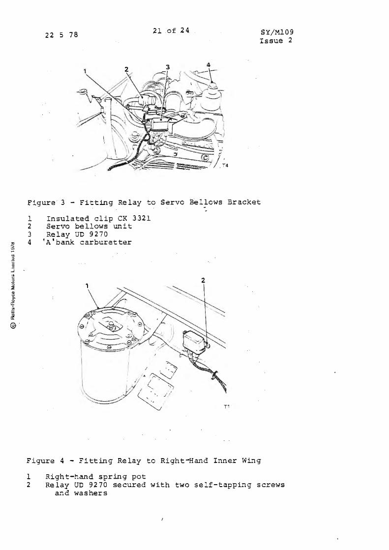
:a ... '!'J po'
" .:.
.J </J ] ,:, ;:; Q) <.I > 0 c:: :l,
£ @ ·
22 5 78 21 of 24 SY/Ml09 Issue 2
Figure 3 - Fitting Relay to Servo Bellows Bracket
l 2 3 4
Insulated clip CK 3321 Servo bellows unit Relay UD 9270
'A'bank carburetter
2
Figure 4 - Fitting Relay to Right-Hand Inner Wing
l Right-hand spring pot 2 Relay UD 9270 secured with two self-tapping screws
and washers
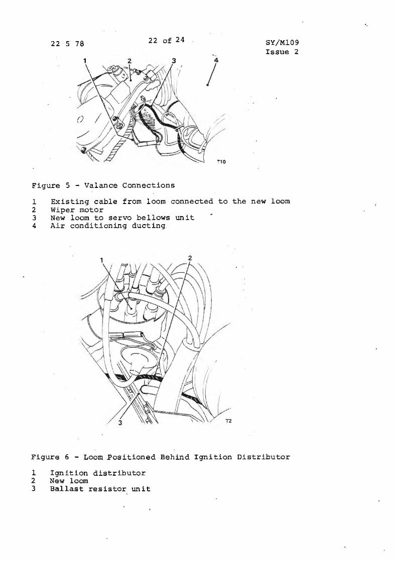
22 5 78 22 of 24 SY/Ml09 Issue 2
1 2 3 4
I I
Figure S - Valance Connections
l Existing cable from loom connected to the new loom 2 Wiper motor 3 New loom to servo bellows unit 4 Air conditioning ducting
Figure 6 - Loom Positioned Behind Ignition Distributor
l Ignition distributor 2 New loom 3 Ballast resistor unit
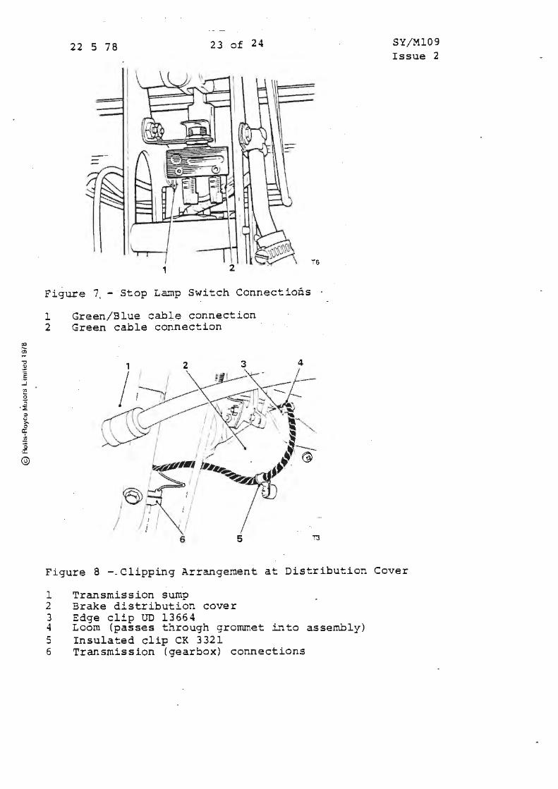
2) ,_ er,
-::,
~
..J <ll
2 :,
· :::E ~ (J >-0 a: i? '3 a::
©
22 5 78 23 of 24
Figure 7. - Stop Lamp Switch Connections
l Green/Blue cable connection 2 Green cable connection
3 4
/~ I
/ /!I 6 5
T6
T3
SY/Ml09 Issue 2
Figure 8 - Clipping Arrangement at Distribution Cover
l Transmission sump 2 Brake distribution cover 3 Edge clip UD 13664 4 Loom (passes through grommet into assembly) 5 Insulated clip CK 3321 6 Transmission (gearbox) connections

22 5 78
' ,,
() -- - .._
24 of 24
- T9
SY/Ml09 Issue 2
Figure 9 - Gearbox Connection and Blanking Plug to be Changed and Removed
1 ~earbox connection to be changed 2 Kick-down solenoid 3 Front servo 4 Blanking plug to be removed and top gear pressure switch fitted
1 2 3
I
L I J- ,1
0 :J' I I
i. )
Figure 10 - Top Gear Pressure Switch and Wire Route
1 Gearbox connection 2 Kick-down solenoid 3 Connecting lead · 4 Front servo 5 Top gear p~essure switch
C)
::t
• erv1ce ulletin
Bulletin n·,.; rrber SY/MllO Cut·.:: 22 9 78 Pa 'Je
C1rculat1on list I I 11 II 11 I 11 11 Ii Category c
ALL FRANCHISE HOLDERS
CHANGES TO SPECIFICATION
APPLICABLE TO:
All Rolls-Royce Silver Shadow I!, Silver Wraith II and Corniche cars and all Bentley T2 and Corniche motor cars from car serial numbers:
Silver Shadow II Silver Wraith II Be:1tley T2 Corniche Saloon Corniche Convertible
INTRODUCTION:
34573 34601 34775 34830 33029
This bulletin describes changes which have been made to the above motor cars.
Full technical details and workshop 'procedures will shortly be issued in a Workshop Manual Supplement.
The following new features have been introduced:
1 Headlamp wash/wipe.
2 Automatic radio aerial control.
3 Manual override for preferential selection of ACU screen or facia airflow.
I
ID)OLLS- · rf\\OYCE !'-.\OTORS
Car Division
~SD 4·i/!
1 of 4
II
22 9 78 2 of 4
The follcwing existing features have been revised:
1 Gearbox actuator and loom assembly.
2 Front foglamp switch and circuit.
3 Rear foglamp circuit
4 Refrigerant compressor circuit.
SY/MllO
5 Full throttle cut-out control on cars fitted with exhaust gas recirculation.
DESCRIPTION:
1 Headlamp wash/wipe
Headlamp wash/wipe has been introduced on all cars except those built to the USA and Canadian specification.
The headlamp and windscreen wash/wipe systems can both be activated by depressing the wash/wipe button on the end of the indicator lever. Whilst the windscreen wash/' wipe will operate at any time when the ignition is switched on, the headlamp wash/wipe will only operate if the headlamps are also switched on.
The headlamps are cleaned by brushes wiping an arc across the headlamp lenses. The brushes are operated by a conventional wiper motor and rack. The motor is situated beneath the left-hand front wing.
The reservoir under the left-hand front wing provides water for both the headlamp and windscreen washers. There are two independent pumps to feed the two washer systems.
2 Automatic radio aerial
An automatic radio aerial has been introduced on all cars.
The ignition must be in the 'ON (RUN} 1 or 'ACCESSORY (ACC' 1
position for the aerial to operate. Switching on the radio will raise the aerial. Switching off the radio lowers it.
3 ACU mode override
A manual override for preferential selection of the airflow through the facia outlets, instead of the screen outlets, has been introduced on all cars.

22 9 78 3 of 4 SY/MllO
4
Operation of the mode override switch, located on the facia in the position previously occupied by th·e aerial switch, will redirect the airflow from the screen outlets to the facia outlets.
Two important points should be noted:
1 The temperature of the air, if redirected, will still be controlled by the upper servo position. Dependent upon the prevailing conditions and the upper temperature selector position, the temperature of air may be either cold or warm.
2 The mode flap overr ide will be deactivated and the ACU will revert to full automatic control if either the ACU function switch or the ignition switch is turned to the 'OFF' position.
Gearbox actuator and loom assembly
Changes have been made to the actuator and loom on all cars.
The screwed plug and socket on the actuator has been deleted. The loom is now an integral part of the actuator and passes through the left-hand side of the transmission tunnel into the car interior.
The loom is connected to the gear selection wiring by a multi-pin plug and socket mounted adjacent to the top left-hand side of the ACU servo unit. Access to the plug and socket is gained by removing the ACU servo trim cover.
The gearchange mode of operation remains unchanged.
5 Front foglamp switch and circuit
The front foglarnp switch and circuit have been revised on all cars except those built to USA , Canadian, Australian and Japanese specification, where foglamps are not included.
The foglarnps are now controlled from a switch panel incorporating a warning light which is illuminated when the fogl~~ps are switched on. The switch panel is situated on the lower facia.
The fcglamps will only illuminate when the foglarnp switch is on and the main lighting switch is in the 'PAID<' or 'HEAD' position.
22 9 78 4 of 4 SY/MllO
6 Rear foglamp circuit
The rear foglamp circuit has been revised on all cars, except those built to the USA, Canadian, Australian and Japanese specification where foglamps are not included.
The rear foglamps are controlled from a switch panel incorporating a warning light, which is illuminated when the foglamps are switched on. The switch panel is situated in the lower facia.
The rear foglamps will only illuminate when the foglamp switch is in the 'ON' position, and side lamps or dipped headlamps are in use. Switching to main beam will extinguish the rear foglamps.
7 Refrigerant compressor circuit
8
This change is applicable to all cars.
The compressor electrical circuit is now permanently earthed so that it is always operating provided that:
1 The engine is running
2 The ambient temperature is above o0 c.
3 The air conditioning unit function switch is not in the 1 0FF' position.
This change has been introduced to reduce the possibility of interior windscreen misting under adverse· conditions.
Exhaust gas recirculation cut-out control
This change only applies to cars built to USA, Canadian, Australian and Japanese specification.
The switch, mounted on the carburetter assembly, which cuts out the exhaust gas recirculation system under full throttle conditions has been deleted.
The exhaust gas racirculation system is now cut out under full throttle conditions by the kickdown switch.
a, I ti; .....
I Service Bulletins
Chapter N ~ Power Assisted Steering
0
Service Bulletin
Bulletin number SY/N13
c,rc~tion hst I 11
Category A
11
ALL nisTRIBUTORS AND RETAILERS
Date
II 11
STEERING BOX PENDULUM LEVER SECURING NUT
APPLICABLE TO:
'
20 12 76 Page
I 11 I 11 I
All Rolls-Royce, Silver Shadow and Bentley 'T' series four door saloon and long wheelbase cars listed in this bulletin.
INTRODUCTION:
It is normal production procedure to check certain fastenings on cars before.they leave the factory. The steering box pendulum lever s~curing nut ,is included in this check.
In the course of such checks insecure nuts have been found on pendulum levers of two new cars not yet released. In both cases the threads of the securing nuts were damaged.
The cause of the problem has been identified and if it exists in service it will be limited to the cars listed in this bulletin.
Although no such fault has been recorded on any car in service we are instructing Distributors and Retailers to carry out a ~heck; the check 1s a simple torque tightness one.
Service Managers are therefore asked to ensure that the owners
li))ou.s- 1
lf\\OYCE MOTORS
Car Division
TSO 4171
1 of 1
11 I I
of cars whose chassis numbers are listed be contacted immediately and asked to bring their car to be checked. In those cases where cars sold by your company are serviced elsewhere, the owner should be requested to take the car to his nearest Rolls-Royce franchise holder.
Satisfactory completion of this work should be identified by two white paint spots on the epaulette on the right hand corner of the radiator top tank and on the lower end of the steering box rocker shaft.
2 of 7 SY/Nl3
The procedure for the check is as follows:
PROCEDURE:
l Place the car on a ramp.
2 Torque tighten the nut, which secures the pendulum lever, to 13,8 kgf.m. (100 lbf. ft.).
3 Check to ensure that the nut tightens satisfactorily to 13,8 kgf.m. (100 lb£. ft). If not carry out operation 4, otherwise carry out operation 5.
4 Remove the securing nut. Fit a new nut and torque tighten to 13,8 kgf.m. (100 lbf.ft.). Return the nut on a service label to Rolls-Royce Motors in the normal manner.
5 Paint spot the radiator and steering box rocker shaft and face to provide visual evidence that the check has been carried out.
'Any cost involved in this check should be claimed on a warranty claim form which should be completed in the normal manner. The reference SY/Nl3 should be used in place of a manhour schedule number.
TIME ALLOWED: 0.40 hours
Hly
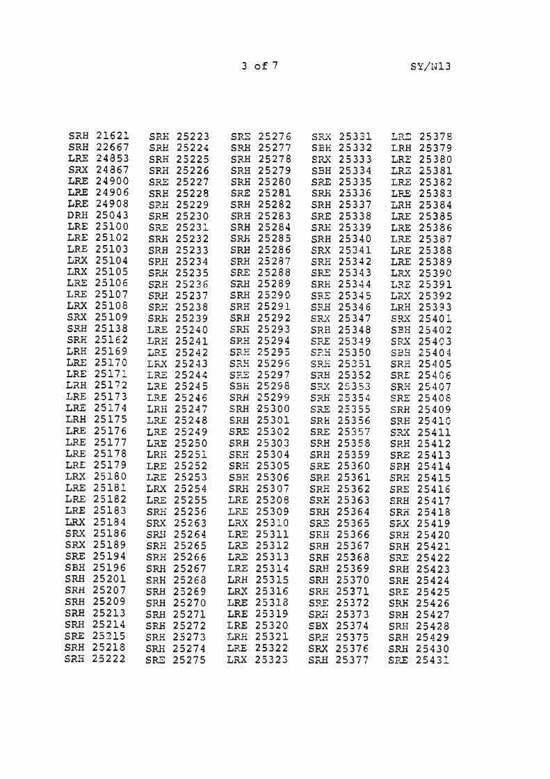
3 of 7 SY/Nl3
SRH 21621 SRH 25223 SRE 25276 SRX 25331 LR!: 25378 SRH 22667 SRH 25224 SRH 25277 SBH 25332 LRH 25379 LRE 24853 SRH 25225 SRH 25278 SRX 25333 LRE 25380 SRX 24867 SRH 25226 SRH 25279 SBH 25334 LRZ 25381 LRE 24900 SRE 25227 SRH 25280 SRE 25335 LRE 25382 LRE 24906 SRE 25228 SRE 25281 SRH 23336 LRE 25383 LRE 24908 SRH 25229 SRH 25282 SRH 25337 · LRH 25384 DRH 25043 SRH 25230 SRH 25283 SRE 25338 LRE 25385 LRE 25100 SRE 25231 SRH 25284 SRH 25339 LRE 25386 LRE 25102 SRH 25232 SRH 25285 SRH 25340 LRE 25387 LRE 25103 SRH 25233 SRH 25286 SRX 25341 LRE 25388 LRX 25104 SRH 25234 SRH 25287 SRH 25342 LRE 25389 LRX 25105 SP..H 25235 SRE 25288 SRE 25343 LR.X 25390 LRE 25106 SRH 25236 SRH 25289 SRH 25344 L~.E 25391 LRE 25107 SRH 25237 SRH 25290 SRE 25345 L ""'x" ~- 25392 LRX 25108 SRH 25238 SRH 25291 SP.H 25346 LRH 25393 SRX 25109 SRH 25239 SRH 25292 SRX 25347 S!lX 25401 SRH 25138 LRE 25240 SRli 25293 SRH 25348 SBH 25402 SRH 25162 LRH 25241 SRH 25294 SRE 25349 SR.X 25403 LRH 25169 LRE 25242 SR.H 25295 S?.5 25350 SES 25404 LRE 25170 LRX 25243 SRE 25296 SRE 25351 SRE 25405 LRE 25171 LRE 25244 SR.E 25297 SR.>! 25352 SRt 254C6 L~H 25172 LRE 25245 SBE 25298 SRX 25353 SRH 25407 LRE 25173 LRE 25246 SRH 25299 SRH 25354 SRE 2540S LRE 25174 LRH 25247 SRH ~5300 SRE 23355 SRH 25409 LRH 25175 LRE 25248 SRH 25301 SRH 25356 SRH 25410 LRE 25176 LRE 25249 SRE 25302 SRE 25357 SRX 25411 LRE 25177 LRE 25250 SRH 25303 SRH 25358 SRH 25412 LRE 25178 LRH 25251 SRH 25304 SRH 25359 SRE 25413 LRE 25179 LRE 25252 SRH 25305 SRE 25360 SRH 25414 LR."{ 25180 LRE 25253 SBH 25306 SRH 25361 SRH 25415 LRE 25181 LRX 25254 SRH 25307 SRH 25362 SRE 25416 LRE 25182 LRE 25255 LRE 25308 SRH 25363 SRH 25417 LRE 25183 SRli 25256 LRE 25309 SRH 25364 SRH 25418 LRX 25184 SRX 25263 LRX 25310 SRE 25365 SRX 25419 SRX 25186 SRH 25264 LRE 25311 SRH 25366 SRH 25420 SRX 25189 SRH 25265 LRE 25312 SRH 25367 SRH 25421 SRE 25194 $RH 25266 LRE 25313 SRH 25368 SRE 25422 SBH 25196 SRH 25267 LRE 25314 SRf! 25369 SRH 25423 SRH 25201 SRH 25268 LRH 25315 SRH 25370 SRH 25424 SRH 25207 SRH 25269 LR.'< 25316 SRH 25371 SRE 25425 SRH 25209 SRH 25270 LRE 25318 SRE 25372 SRH 25426 SRH 25213 SRH 25271 LRE 25319 SRH 25373 SRH 25427 SRH 25214 SRH 25272 LRE 25320 SBX 25374 SRH 25428 SRE 25215 SRH 25273 LRH 25321 SP..H 25375 SRH 25429 SRH 25218 SRH 25274 LRE 25322 SRX 25376 SRH 25430 SRH 25222 SRE 25275 LRX 25323 SP.H 25377 SR.E 25431
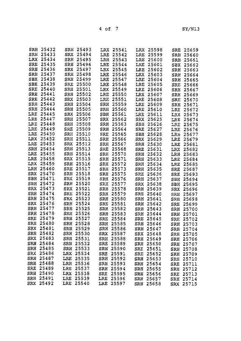
4 of 7 SY/Nl3
SRH 25432 SRH 25493 LRX 25541 LRX 25598 SRE 25659 SRH 25433 SRX 25494 LRE 25542 LRE 25599 SRH 25660 LRX 25434 SRH 25495 LRH 25543 LRE 25600 SRH 25661 SRE 25435 SRH 25496 LRE 25544 LRE 25601 SBX 25662 SRH 25436 SRX 25497 LRX 25545 LRE 25602 SRH 25663 SRH 25437 SRH 25498 LRE 25546 LRX 25603 SRH 25664 SBX 25438 SRH 25499 LRE 25547 LRE 25604 SRH 25665 SBX 25439 SRE 25500 LRE 25548 LRE 25605 SRE 25666 SRE 25440 SRH 25501 LRX 25549 LRE 25606 SRH 25667 SRH 25441 SRH 25502 LRE 25550 LRX 25607 SRH 25669 SRE 25442 SRX 25503 LRE 25551 LRE 25608 SRE 25670 SRH 25443 SRH 25504 SRH 25559 LRE 25609 SRH 25671 SRH 25444 SRH 25505 SRH 25560 LRE 25610 LRE 25672 LRE 25445 SRX 25506 SBH 25561 LRE 25611 LRX 25673 LRE 25447 SRH 25507 SRX 25562 SRX 25625 LRE 25674 LRE 25448 SRH 25508 SRH 25563 SBH 25626 LRE 25675 LRE 25449 SRE 25509 SRH 25564 SRE 25627 LRE 25676 LRE 25450 SRH 25510 SRE 25565 SBH 25628 LRH 25677 LRX 25452 SRH 25511 SRH 25566 SRX 25629 LRE 25679 LRE 25453 SRX 25512 SRH 25567 SRH 25630 LRE 25681 SRH 25454 SRH 25513 SRE 25568 SRE 25631 LRX 25682 LRE 25455 SRH 25514 SRH 25570 SRH 25632 LRH 25683 LRE 25458 SRX 25515 SRH 25571 SRH 25633 LRE 25684 LRX 25459 SRH 25516 SRH 25572 SRH 25634 LRE 25685 LRH 25460 SRE 25517 SRH 25573 SRH 25635 SRE 25687 SRX 25470 SRH 25518 SRH 25575 SRE 25636 SRE 25693 SBH 25471 SRX 25519 SP.H 25576 SRH 25637 SBH 25694 SBH 25472 SRH 25520 SRH 25577 SRX 25638 SBH 25695 SRX 25473 SRX 25521 SRH 25578 SRH 25639 SRX 25696 SRH 25474 SRH 25522 SRH 25579 SRE 25640 SRH 25697 SRH 25475 SRX 25523 SRH 25580 SRH 25641 SRH 25698 SRX 25476 SRH 25524 SRE 25581 SRH 25642 SRE 25699 SRH 25477 SRH 25525 SRH 25582 SRH 25643 SRH 25700 SRH 25478 SRH 25526 SRH 25583 SRH 25644 SRH 25701 SRE 25479 SRH 25527 SRE 25584 SRE 25645 SR.E 25702 SRH 25480 SRH 25528 SRH 25585 SRH 25646 SRH 25703 SRX 25481 SRH 25529 SRH 25586 SRH 25647 SRH 25704 SRH 25482 SRH 25530 SRX 25587 SRX 25648 SRH 25705 SRX 25483 SRH 25531 SRH 25588 SRH 25649 SRH 25706 SRH 25484 SRH 25532 SRE 25589 SRH 25650 SRH 25707 SRH 25485 SRH 25533 SRH 25590 SRE 25651 SRH 25708 SRX 25486 LRX 25534 SRE 25591 SRE 25652 SRH 25709 SRH 25487 LRE 25535 SRH 25592 SRH 25653 SRH 25710 SRH 25488 LRH 25536 SRH 25593 SRH 25654 SRE 25711 SRE 25489 LRE 25537 SRH 25594 SRH 25655 SRH 25712 SRH 25490 LRX 25538 SRE 25595 SRH 25656 SRE 25713 SRH 25491 LRE 25539 LRE 25596 SRH 25657 SRH 25714 SRX 25492 LRE 25540 LRE 25597 SRH 25658 SRX 25715
5 of 7 SY/Nl3
SRH 25716 SRE 25774 SBH 25834 LRE 25885 SRH 25938 SRH 25717 SRH 25775 SRE 25835 LRE 25886 SRS 25939 SRE 25718 SRE 25776 SBH 25836 LRE 25888 SRH 25940 SRH 25719 SRH 25777 SRE 25837 LRE 25889 LRE 25941 SRH 25720 SRE 25778 SRH 25838 LRE 25890 LRX 25942 SRE 25721 SRH 25779 SRH 25839 LRE 25891 LRE 25943 SRH 25722 SRE 25780 SRH 25840 LRE 25892 LRE 25944 SRH 25723 SRH 25781 SRH 25841 LRH 25893 LRE 25945 SRH 25724 SRH 25782 SRE 25842 LRE 25894 LRE 25946 SRH 25725 SRli 25783 SRH 25843 SRX 25895 LRX 25947 SRH 25726 SRE 25784 SRE 25844 SRH 25896 LR.E 25948 SRE 25727 SRH 25785 SRH 25845 SBH 25897 LRE 25949 SRH 25728 SRH 25786 SRE 25846 SBH 25898 LRE 25950 SRH 25729 SRE 25787 SRH 25847 SRE 25899 LRH 25951 SRE 25730 SRH 25788 SRX 25848 SBH 25900 LRE 25952 SRH 25731 SRH 25789 SRH 25849 SRH 25901 LRH 25954 SRH 25732 SRH 25790 SRE 25850 SRE 25902 LRE 25955 SRX 25733 SRE 25791 SRH 25851 SRH 25903 LRE 25956 SRH 25734 SRH 25792 SRE 25852 SRH 25904 SRH 25965 SRH 25735 SRH 25793 SRH 25853 SRH 25905 SBH 25966 SRE 25736 SRH 25794 SRH 25854 SRH 25906 SBH 25968 SRH 25737 SRH 25795 SRH 25855 SRE 25907 SRE 25969 SRH 25738 SRH 25796 SRH 25856 SRH 25908 SRH 25970 LRE 25739 SRH 25797 SRH 25857 SRE 25909 SRH 25972 LRE 25740 SRE 25798 SRE 25858 SRH 25910 SRX 25973 LRX 25741 SRH 25799 SRH 25859 SRH 25911 SRE Z5976 LRE 25742 SRH 25800 SRH 25860 SRE 25912 SRH 25977 LRE 25743 SRE 25801 SRE 25861 SRH 25913 SRX 25978 LRE 25744 SRH 25802 SRH 25862 SRH 25914 SRH 25979 LRH 25745 SRH 25803 SRH 25863 SRH 25915 SRH 25980 LRE 25746 SRE 25804 SRX 25864 SRE 25916 SRE 25981 LRE 25747 SRH 25805 SRH 25865 SRH 25917 SRH 25982 LRX 25748 SRH 25806 SRH 25866 SRH 25918 SRX 25984 LRE 25749 SRH 25807 SRE 25867 SRH 25920 SRH 25986 LRE 25750 SRH 25808 SRH 25868 SRE 25921 SRE 25987 LRE 25751 SRH 25809 SRE 25869 SRE 25922 SRH 25988 LRE 25752 LRE 25810 SRH 25870 SRH 25923 SRH 25989 LRE 25754 LRH 25811 SRH 25871 SRH 25924 SRH 25990 SBX 25762 LRE 25812 SRH 25872 SRH 25925 SRH 25992 SRX 25763· LRX 25813 SRH 25873 SRE 25926 SRE 25993 SBH 25764 LR.E 25814 SRH 25874 SRH 25927 SRH 25994 SRE 25765 LRE 25815 SRE 25875 SRH 25928 SRE 25995 SRX 25766 LRH 25816 SRH 25876 SRE 25929 SRH 25996 SBH 25767 LRE 25817 SRH 25877 SRH 25930 SRH 25997 SRE 25768 LRX 25818 SRE 25878 SRE 25931 SRH 25998 SRH 25769 LRE 25820 LRE 25879 SRH 25932 SRE 25999 SRE 25770 SRE 25821 LRE 25880 SRH 25933 SRH 25600 SRH 25771 SRE 25822 LRE 25882 SRH 25934 SRH 26001 SRX 25772 LRE 25823 LRE 25883 SRH 25936 SRH 26003 SRH 25773 LRX 25824 LRE 25884 SRH 25937 SRH 26004
6 of 7 SY/Nl3
SRH 26005 SRE 26076 LRE 26145 SRE 26235 SRH 26326 SRE 26006 SRH 26077 LRH 26146 SRH 26236 SRH 26327 LRX 26007 SRH 26078 LRE 26148 SRH 26237 SRE 26328 LRE 26008 SRH 26079 LRE 26149 SRH 26239 SRH 26329
\. LRE 26011 SRE 26080 LRE 26150 SRH 26240 SRH 26330 LRH 26012 SRH 26081 LRE 26151 SRH 26243 SRH 26331 LRE 26013 SRE 26083 SRE 26161 SRE 26244 LRE 26334 LRE 26014 SRH 26084 SBH 26162 SRH 26245 LRX 26346 LRE 26015 SRH 26085 SBH 26163 SRH 26246 SBH 26355 LRX 26016 ,sRH 26087 SRE 26164 SRH 26250 SRH 26356 LRE 26017 SRH 26089 SRH 26165 SRH 26252 SRH 26358 LRE 26019 SRH 26091 SRH 26167 SRH 26253 SRH 26359 LRE 26020 SRH 26093 SRH 26168 SRH 26254 SRE 26360 LRE 26021 SRE 26094 SRE 26169 SRH 26255 SRH 26361 SRH 26028· SBH 26095 SRH 26170 SRH 26257 SRH 26362 SRE 26029 SRH . i"6097 SRH 26172 SRH 26258 SRH 26364 SRE 26030 SRH 26098 SRH 26173 SRH 26260 SRH 26366 SBH 26031 SRH 26099 SRX 26174 SRH 26262 SRH 26369 SRE 26032 SR.E 26100 SRH 26175 SRH 26264 SRE 26370 SBH 26034 SRH 26101 SRH 26 176 SRH 26266 SRH 26371 SRE 26035 SRE 26102 SRH 26178 LRE 26268 SRH 26377 SRE 26036 SRH 26103 SRH 26179 LRX 26275 SRE 26378 SBH 26037 SRH 26104 SRH 26181 LRE 26276 SRH 26379 SRE 26038 SRH 26105 SRH 26186 LRE 26281 SRH 26381 SRX 26039 SRH 26107 SRH 26188 SRE 2-6286 SRH 26387· SRH 26040 SRE 26108 SRE 26189 SBH 26287 . SRE 26397 SRE 26042 SRH 26109 SRH 26190 SRE 26288 SRH 26400 SRH 26043 SRH 26111 SRH 26193 SBH 26289 LRE 26406· SRX 26044 SRH 26112 SRH 26195 SRH 26291 LRX 26411 SRH 26045 SRH 26113 SRH 26197 SRH 26292 SRE 26421 SRX 26046 SRH 26115 SRH 2619.9 SRH 26294 SRE 26423 SRH 26047 SRB 26117 SRH 26201 SRH 26295 SRE 26425 SRE 26049 SRH 26118 SRX 26202 SRH 26297 SRE 26427 SRH 26050 SRH 26'119 SRH 26203 SRX 26299 SRE 26430 SRE 26051 SRE 26122 SRX 26204 SRH 26300 SRH 25431 SRH 26053 SRH 26123 LRE 26206 SRH 26302 SRX 26432 SRX 26054 SRH 26124 LRE 26208 SRH 26304 SRH 26436 SRH 26055 SRH 26125 LRE 26209 SRH 26305 SRE 26445 SRH 26056 SRE 26126 LRE 26212 SRE 26306 SRH 26447--SRE 26057 SRH 26127 LRX 26213 SRH 26307 SRH 26454 SRE 26060 SRH 26128 LRE 26216 SRH 26308 SRH 26456 SRH 26061 SRH 26130 LRE 26217 ·SRX 26309 SRH 26457 SRE 26062 SRH 26131 LRE 26218 SRX 26310 SRH . 26459 SRH 26063 SRB 26132 SBH 26222 SRE 26311 SRH 26466 SRH 26065 SRH 26133 SRX 26223 SRH 26313 LRX 26471 SRE 26066 SRE 26135 SBH 26224 SRH 26315 LRE 26474 SRH 26067 SRH 26137 SRH 26226 SRH 26316 LRE 26483 SRH 26069 SBX 26138 SRH 26229 SRH 26318 SRE 26507 SRX 26070 SRH 26139 SRH 26230 SRH 26321 SRH 26508 SRE 26073 LRE 26140 SRE 26322 SRH 26512 SRE 26074 I.RE 26141 SRX 26232 SRH 26323 SRE 26514 SRH 26075 LRE 26143 SRH 26234 SRH 26324 SRE 26518 .
SRE 26526
LRX 26537 LRE 26539 I.RE 26540 LRE 26542 LR.H 26543 LRE 26544 LRE 26545 LRE 26547 SRli 26558 SRX 26564 SRX 26566 SIU1 26568 SRE 26569 SRE 26581 SRE 26583 SU 26590 SRE 26597 SIU1 26599 LRX 26621
SRE 26647 SRE 26653 SRH 26657 SR.B 26661 SRX 26663 LRH 26673 LRE 26690 LRE 26697 SRE 26700
7 of 7
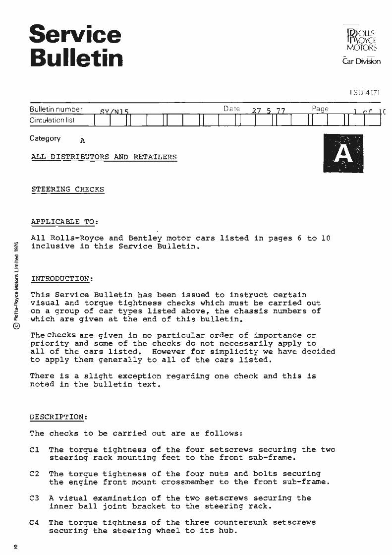
Service Bulletin
Bulletin number SY/NJ I
Circu-4ation list I I Date
11 11 11
Page 27 5 77 11 I I II
I ID)OLLS· ff\\OYCE I MOTORS J
Car Division
TSO 4171
11
Category A
ALL DISTRIBUTORS AND RETA'ILERS El STEERING CHECKS
APPLICABLE TO:
All Rolls-Royce and Bentley motor cars listed in pages 6 to 10 inclusive in this Service Bulletin.
INTRODUCTION:
This Service Bulletin has been issued to instruct certain visual and torque tightness checks which must be carried out on a group of car types listed above, the chassis numbers of which are given at the end of this bulletin.
The checks are given in no particular order of importance or priority and some of the checks do not necessarily apply to all of the cars listed. However for simplicity we have decided to apply them generally to all of the cars listed.
There is a slight exception regarding one check and this is noted in the bulletin text.
DESCRIPTION:
The checks to be carried out are as follows:
Cl The torque tightness of the four setscrews securing the two steering rack mounting feet to the front sub-frame.
C2 The torque tightness of the four nuts and bolts securing the engine front mount crossmember to the front sub-frame.
C3 A visual examination of the two setscrews securing the inner ball joint bracket to the steering rack.
C4 The torque tightness of the three countersunk setscrews securing the steering wheel to its hub.
27 5 77 2 of 10 SY/NlS
Figures 1 and 2 show details of the areas where these checks and visual examinations are to be carried out.
PROCEDURE:
Check Cl
Steering Rack Mounting Feet to Front Sub-frame
The four setscrews fastening the steering rack to the sub-frame are torque tightened on assembly to between 5,8 kg.m. and 6,2 kg.m. (42 lb.ft. and 45 lb.ft.). The following procedure should be used to ensure that the torque tightness is correct:
1. Raise the car on a hoist.
2. Check the torque of the four setscrews shown in Figure 1, item Cl. The correct figures are 5,8 kg.m. to 6,2 kg.m. (42 lb.ft. to 45 lb.ft.) and the check should be made using a 5/8 in. A/F socket and universal joint, extension bar and normal torque spanner.
Check C2 Front Engine Mount Crossmember to Sub-frame Nuts and Bolts
Torque figure for the four engine mount crossmember nuts and bolts should be 11,7 kg.m. to 12,5 kg.m. (85 lb.ft. to 90 lb.ft.). This is a revised figure from the previous one which was 8,3 kg.m. to 9,0 kg.m. (60 lb.ft. to 65 lb.ft.}.
1. Raise the car on the hoist.
2. Check the torque of the four nuts and bolts shown in Figure 1 item C2 using a normal torque spanner and socket, and raise to the revised torque figure if necessary.
Check C3
Visual Inspection of the Inner Ball Joint Bracket to Steering Rack Setscrews
Using the procedure outlined below, a visual check must be carried out on the fasteners of the steering rack and pinion inner ball joint bracket. The two setscrews should carry the marking "GKN M 8.8". If the marking is incorrect then the setscrews must be removed and returned with a service label quoting this Service Bulletin Number. If the marking is correct do not disturb the locking plate or setscrews.
l. With the car raised on the hoist.
27 5 77 3 of 10 SY/NlS
2. Visually inspect the two setscrews securing the inner ball joint bracket to the steering rack as shown in Figure 1, item C3. The setscrews should carry the wording "GKN M 8.8 11
•
If the wording is incorrect then the setscrews must be renewed as follows.
3. Knock back the locking tabs.
4. Unscrew and remove the incorrectly worded setscrews.
5. Fit new setscrews part number SPM 1278 and new lock plate SPM 1279.
6. The setscrews should be torque tightened to 3,8 kg.m. to 4,1 kg.m. (27.5 lb.ft. to 30 lb.ft.) and the lock tabs correctly turned over.
7. Any incorrectly worded setscrews should be returned to R-RM on a service label quoting this Service Bulletin number.
Check C4
Steering Wheel to Hub (Excluding Camargue and Corniche cars)
Using the procedure outlined below check the torque tightness of the three countersunk setscrews shown in Figure 2 item C4 which secure the steering wheel to the hub.
The correct torque figure is 0,8 kg.m. to 1,1 ~g.w. (€ lb.ft. to 8 lb.ft.}.
1. Disconnect the battery.
2. Feed 31 cm. (12.0 in.) of strong thin cord in a loop into the gap between the horn button and steering wheel inner rim to lie against the spindle.
3. Simultaneously pull both ends of the cord sharply and pull the horn button from the wheel. Remove the contact plate.
4. Check the torque tightness of the three countersunk steering wheel to hub setscrews. The correct figure is 0,8 kg.m. to 1,1 kg.m. (6 lb.ft. to 8 lb.ft.). Should any of the screws be below these figures then the screws must be removed and any locking material removed from the threads of the screws and hub.
5. The screws should then be re-fitted using Loctite 602 and correctly torque tightened.
6 . Refit the contact plate.
7 . Fit the horn button and connect the battery.
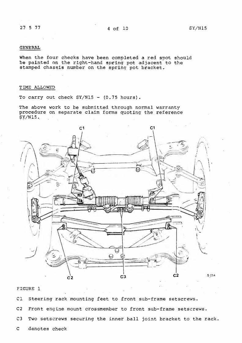
21 5 77 4 of 10 SY/NlS
GENERAL
When the four checks have been completed a red spot should be painted on the right-hand spring pot adjacent to the stamped chassis number on the spring pot bracket.
TIME ALLOWED
To carry out check SY/NlS - (0.75 hours).
The above work to be submitted through normal warranty procedure on separate claim forms quoting the reference SY/NlS.
C1 C1
,• . \ '-'
\ I I
-._1 I
_j
C3 C2
FIGURE 1
Cl Steering rack mounting feet to front sub-frame setscrews.
C2 Front engine mount crossmember to front sub-frame setscrews.
S 214
C3 Two setscrews securing the inner ball joint bracket to the rack.
C denotes check
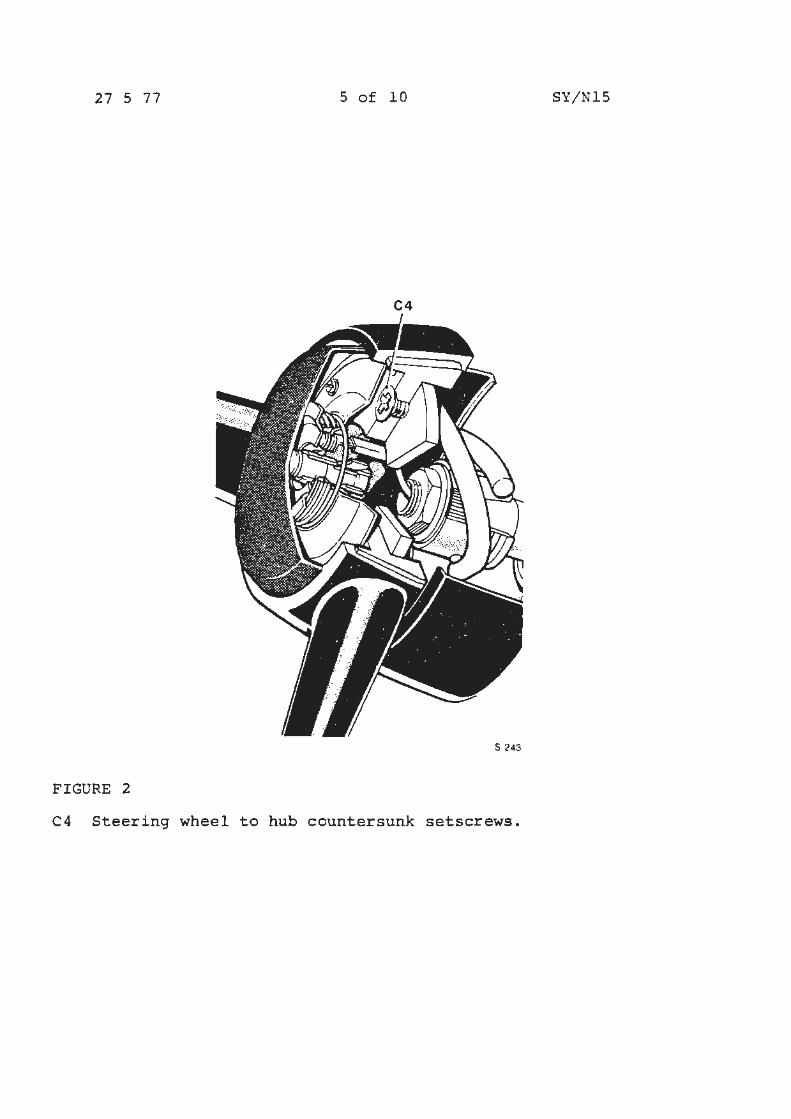
27 5 77 5 of 10 SY/NlS
C4
S 243
FIGURE 2
C4 Steering wheel to hub countersunk setscrews.

27 5 77 6 of 10 SY/NlS
SRF 30001 SRX 30051 DRH 30101 SRF 30151 SRH 30201 SRF 30002 SBH 30052 CRH 30102 SRH 30152 SRX 30202 DRH 30003 SBH 30053 DRX 30103 SRH 30153 SRH 30203 SRH 30004 SBH 30054 ORF 30104 SRH 30154 SRH 30204 SRF 30005 SBH 30055 ORF 30105 SRH 30155 SRF 30205 SRF 30006 SRF 30056 CRF 30106 LRF 30156 SRH 30206 SRH 30007 SRH 30057 SRX 30107 LRF 30157 SRF 30207 SRX 30008 SRH 30058 SRF 30108 LRF 30158 SRH 30208 DRX 30009 SRH 30059 SRH 30109 LRX 30159 SRX 30209 DRX 30010 SRF 30060 SRF 30110 LRX 30160 SRH 30210 CRX 30011 SRH 30061 SRH 30111 LRF 30161 SRF 30211 DRX 30012 SRH 30062 SRF 30112 LRF 30162 SRH 30212 DRX 30013 SRF 30063 SRH 30113 LRF 30163 SRF 30213 CRX 30014 SRH 30064 SRF 30114 LRH 30164 SRH 30214 JRH 30015 SRF 30065 SRF 30115 LRF 30165 SRX 30215 DRX 30016 SRH 30066 SRH 30116 LRF 30166 SRH 30216 DRX 30017 SRH 30067 SRF 30117 LRF 30167 SRF 30217 CRX 30018 SRH 30068 SRF 30118 LRF 30168 SRH 30218 CRX 30019 SRH 30069 SRH 30119 LRX 30169 SRF 30219 DRX 30020 SRH 30070 SRF 30120 LRF 30170 SRH 30220 CRH 30021 SRH 30071 SRH 30121 LRF 30171 SRX 30221 DRH 30022 SRH 30072 SRF 30122 CRF 30172 SRH 30222 CRX 30023 SRH 30073 SRH 30123 DRF 30173 SRH 30223 CRX 30024 SRF 30074 SRX 30124 DRF 30174 SRF 30224 CRX 30025 SRH 30075 SRF 30125 CRH 30175 SRH 30225 CRX 30026 SRH 30076 SRH 30126 DRF 30176 SRH 30226 CRH 30027 SRF 30077 SRX 30127 DRF 30177 SRF 30227 ORX 30028 SRH 30078 SRF 30128 ORF 30178 SRH 30228 DRH 30029 SRH 30079 SRH 30129 CRX 30179 SRH 30229 JRX 30030 SRH 30080 SRF 30130 JRX 30180 LRF 30230 CRX 30031 SRH 30081 SRH 30131 SRF 30181 LRF 30231 CRX 30032 SRH 30082 SRH 30132 SRX 30182 LRF 30232 DRX 30033 SRH 30083 SRF 30133 SRH 30183 LRH 30233 CRX 30034 SRH 30084 SRH 30134 SRF 30184 LRF 30234 JRH 30035 SRH 30085 SRF 30135 SRH 30185 LRF 30235 JRX 30036 SRH 30086 SRH 30136 SRF 30186 LRF 30236 CRX 30037 SRH 30087 SRH 30137 SRH 30187 LRF 30237 ORH 30038 SRH 30088 SRF 30138 SRX 30188 LRX 30238 CRX 30039 SRH 30089 SRH 30139 SRH 30189 LRF 30239 JRX 30040 SRH 30090 SRH 30140 SRF 30190 LRF 30240 SRX 30041 SRH 30091 SRF 30141 SRF 30191 LRF 30241 SRX 30042 LRH 30092 SRF 30142 SRH 30192 LRH 30242 SRX 30043 LRF 30093 SRH 30143 SRF 30193 LRF 30243 SRX 30044 LRF 30094 SRH 30144 SRH 30194 LRF 30244 SRX 30045 LRF 30095 SRF 30145 SRX 30195 LRF 30245 SBX 30046 LRF 30096 SRH 30146 SRF 30196 CRF 30246 SRX 30047 LRX 30097 SRF 30147 SRH 30197 DRX 30247 SRX 30048 LRF 30098 SRH 30148 SRF 30198 ORF 30248 SRX 30049 CRX 30099 SRF 30149 SRH 30199 CRX 30249 SRX 30050 ORF 30100 SRH 30150 SRF 30200 ORF 30250

27 5 77 7 of 10 SY/NlS
DRF 30251 SRF 30301 SRX 30351 SRH 30401 SRF 30451 DRF 30252 SRF 30302 SRX 30352 SRF 30402 SRH 30452 CRF 30253 SRX 30303 SRH 30353 SRH 30403 LRF 30453 JRX 30254 LRF 30304 SRF 30354 SRX 30404 LRF 30454 SRH 30255 LRF 30305 SRX 30355 SRH 30405 LRX 30455 SRF 30256 LRH 30306 SRH 30356 SRF 30406 LRF 30456 SRH 30257 LRF 30307 SRX 30357 SRF 30407 LRF 30457 SRX 30258 LRF 30308 SRF 30358 SRH 30408 LRF 30458 SRH 30259 LRF 30309 SRH 30359 SRX 30409 DRF 30459 SRF 30260 LRF 30310 SRX 30360 SRH 30410 DRF 30460 SRH 30261 LRX 30311 SRH 30361 SRF 30411 CRX 30461 SRF 30262 LRF 30312 SRH 30362 SRH 30412 ORF 30462 SRH 30263 LRF 30313 SRF 30363 SRX 30413 CRF 30463 SRH 30264 LRF 30314 SRX 30364 SRH 30414 DRF 30464 SRH 30265 LRF 30315 LRF 30365 SRX 30415 CRX 30465 SRF 30266 LRF 30316 LRF 30366 SRH 30416 JRX 30466 SRH 30267 LRH 30317 LRX 30367 SRF 30417 SRX 30467 SRF 30268 LRH 30318 LRF 30368 SRH 30418 SRH 30468 SRH 30269 LRH 30319 LRF 30369 SRX 30419 SRF 30469 SRX 30270 JRH 30320 LRF 30370 SRF 30420 SRH 30470 SRH 30271 JRX 30321 LRF 30371 SRH 30421 SRX 30471 SRF 30272 SRH 30322 LRF 30372 SRF 30422 SRH 30472 SRH 30273 SRF 30323 LRF 30373 SRH 30423 SRF 30473 SRF 30274 SRX 30324 LRF 30374 SRX 30424 SRH 30474 SRH 30275 SRH 30325 LRH 30375 SRH 30425 SRX 30475 SRX 30276 SRF 30326 LRF 30376 SRF 30426 SRH 30476 SRH 30277 SRX 30327 LRF 30377 SRH 30427 SRF 30477 SRF 30278 SRH 30328 DRH 30378 SRX 30428 SRX 30478 SRH 30279 SRF 30329 ORF 30379 SRH 30429 SRH 30479 SRF 30280 SRX 30330 CRX 30380 SRH 30430 SRH 30480 SRH 30281 SRH 30331 DRF 30381 SRF 30431 SRH 30481 SRH 30282 SRF 30332 DRF 30382 SRH 30432 SRF 3('482 SRX 30283 SRX 30333 CRH 30383 SRX 30433 SRH 30483 SRH 30284 SRH 30334 DRH 30384 SRH 30434 SRX 30484 SRF 30285 SRF 30335 CRF 30385 SRF 30435 SRH 30485 SRH 30286 SRX 30336 JRX 30386 SRH 30436 SRF 30486 SRF 30287 SRX 30337 JRX 30387 SRX 30437 SRH 30487 SRH 30288 SRH 30338 SRX 30388 SRH 30438 SRX 30488 SRX 30289 SRF 30339 SRH 30389 SRX 30439 SRH 30489 SRH 30290 SRX 30340 SRX 30390 SRH 30440 SRH 30490 SRF 30291 SRH 30341 SRH 30391 SRF 30441 SRH 30491 SRH 30292 SRX 30342 SRX 30392 SRH 30442 SRF 30492 SRF 30293 SRF 30343 SRH 30393 SRH 30443 SRH 30493 SRH 30294 SRH 30344 SRF 30394 SRH 30444 SRF 30494 SRH 30295 SRX 30345 SRX 30395 SRH 30445 SRH 30495 SRH 30296 SRF 30346 SRX 30396 SRF 30446 SRH 30496 SRF 30297 SRH 30347 SRH 30397 SRH 30447 SRH 30497 SRH 30298 SRX 30348 SRF 30398 SRH 30448 SRF 30498 SRF 30299 SRF 30349 SRH 30399 SRH 30449 SRH 30499 SRX 30300 SRR 30350 SRX 30400 SRH 30450 SRX 30500
27 5 77 8 of 10 SY/Nl5
SRH 30501 SRH 30551 LRH 30601 SRF 30651 SRH 30701 SRH 30502 SRX 30552 LRX 30602 SRH 30652 SRF 30702 SRF 30503 SRF 30553 LRX 30603 SRH 30653 SRH 30703 SRH 30504 SRH 30554 LRF 30604 SRX 30654 SRX 30704 SRH 30505 SRX 30555 LRX 30605 SRH 30655 SRH 30705 SRX 30506 SRH 30556 SRF 30606 LRF 30656 SRH 30706 SRH 30507 SRH 30557 SRX 30607 LRH 30657 SRF 30707 SRH 30508 SRX 30558 SRH 30608 LRF 30658 SRH 30708 SRF 30509 SRH 30559 SRH 30609 LRX 30659 SRF 30709 SRH 30510 SRF 30560 SRF 30610 LRF 30660 SRH 30710 SRH 30511 SRH 30561 SRH 30611 LRX 30661 SRX 30711 SRH 30512 SRX 30562 SRH 30612 LRF 30662 SRH 30712 SRH 30513 SRH 30563 SRF 30613 LRH 30663 SRF 30713 SRH 30514 SRF 30564 SRH 30614 LRF 30664 SRH 30714 SRF 30515 SRH 30565 SRH 30615 LRX 30665 SRH 30715 SRH 30516 SRH 30566 SRX 30616 LRF 30666 SRH 30716 ORF 30517 SRX 30567 SRH 30617 LRX 30667 SRH 30717 CRF 30518 SRH 30568 SRH 30618 LRF 30668 SRF 30718 DRH 30519 SRX 30569 SRF 30619 LRX 30669 SRH 30719 ORF 30520 SRH 30570 SRX 30620 LRF 30670 SRF 30720 CRX 30521 SRF 30571 SRH 30621 LRF 30671 SRH 30721 DRX 30522 SRH 30572 SRH 30622 ORF 30672 SRH 30722 JRX 30523 SRX 30573 SRF 30623 DR,'{ 30673 SRH 30723 SRX 30524 SRH 30574 SRH 30624 DRH 30674 SRH 30724 SRH 30525 SRH 30575 SRH 30625 DRF 30675 SRF 30725 SRX 30526 SRF 30576 SRX 30626 ORF 30676 SRH 30726 SRH 30527 SRH 30577 SRH 30627 ORX 30677 SRF 30727 SRF 30528 SRX 30578 SRH 30628 CRF 30678 SRH 30728 SRH 30529 SRH 30579 SRF 30629 CRH 30679 SRH 30729 SRX 30530 SRF 30580 SRH 30630 JRX 30680 SRH 30730 SRH 30531 SRH 30581 SRX 30631. JRX 30681 SRH 30731 SRX 30532 SRH 30582 SRH 30632 SRX 30682 LRF 30732 SRH 30533 SRH 30583 SRF 30633 SRH 30683 LRF 30733 SRF 30534 SRH 30584 SRH 30634 SRX 30684 LRH 30734 SRH 30535 SRH 30585 SRH 30635 SRH 30685 LRF 30735 SRX 30536 LRF 30586 SRX 30636 SRF 30686 LRF 30736 SRX 30537 LRH 30587 SRH 30637 SRH 30687 LRX 30737 SRH 30538 LRX 30588 SRH 30638 SRH 30688 LRF 30738 SRF 30539 LRF 30589 SRF 30639 SRX 30689 LRH 30739 SRH 30540 LRX 30590 SRH 30640 SRH 30690 LRF 30740 SRX 30541 LRF 30591 SRH 30641 SRF 30691 LRX 30741 $RH 30542 LRX 30592 SRH 30642 SRH 30692 LRF 30742 SRX 30543 LRF 30593 SRF 30643 SRX 30693 LRF 30743 SRH 30544 LRX 30594 SRH 30644 SRH 30694 LRF 30744 SRF 30545 LRF 30595 SRH 30645 SRX 30695 LRH 30745 SRX 30546 LRX 30596 SRX 30646 SRH 30696 LRF 30746 SRH 30547 LRH 30597 SRH 30647 SRF 30697 LRX 30747 SRX 30548 LRF 30598 SRH 30648 SRH 30698 ORF 30748 SRH 30549 LRX 30599 SRF 30649 SRX 30699 DRX 30749 SRF 30550 LRF 30600 SRH 30650 SRH 30700 DRH 30750
27 5 77 9 of 10 SY/NlS
CRX 30751 SRH 30801 SRH 30851 CRX 30901 SRH 30951 ORF 30752 SRH 30802 SRF 30852 ORF 30902 SRH 30952 DRF 30753 SRF 30803 SRF 30853 DRX 30903 SRH 30953 JRH 30754 SRH 30804 SRH 30854 CRX 30904 SRH 30954 JRF 30755 SRF 30805 SRH 30855 JRF 30905 SRF 30955 SRX 30756 LRF 30806 SRH 30856 SRH 30906 LRF 30956 SRH 30757 LRF 30807 SRF 30857 SRH 30907 LRH 30957 SRX 30758 LRH 30808 SRH 30858 SRH 30908 LRF 30958 SRH 30759 LRF 30809 SRH 30859 SRH 30909 LRX 30959 SRH 30760 LRH 30810 SRX 30860 SRF 30910 LRF 30960 SRF 30761 LRF 30811 SRH 30861 SRH 30911 LRF 30961 SRH 30762 LRX 30812 SRF 30862 SRH 30912 LRH 30962 SRX 30763 LRF 30813 SRH 30863 SRH 30913 LRF 30963 SRH 30764 LRX 30814 SRX 30864 SRF 30914 LRX 30964 SRF 30765 LRF 30815 SRH 30865 SRH 30915 LRF 30965 SRH 30766 LRX 30816 SRF 30866 SRH 30916 LRX 30966 SRH 30767 LRF 30817 SRH 30867 SRH 30917 LRF 30967 SRH 30768 LRX 30818 SRH 30868 SRH 30918 LRX 30968 SRF 30769 LRF 30819 SRX 30869 SRH 30919 LRX 30970 SRH 30770 LRX 30820 SRH 30870 SRF 30920 LRF 30971 SRH 30771 LRF 30821 SRH 30871 SRH 30921 SRH 30982 SRF 30772 CRX 30822 SRF 30872 SRH 30922 SRH 30983 SRH 30773 DRX 30823 SRH 30873 SRH 30923 SRH 30985 SRX 30774 DRF 30824 SRH 30874 SRH 30924 SRH 30986 SRH 30775 CRH 30825 SRH 30875 SRH 30925 SRH 30987 SRF 30776 DRF 30826 SRH 30876 SRF 30926 SRH 30989 SRH 30777 DRX 30827 SRH 30877 SRH 30927 SRH 30990 SRX 30778 CRX 30828 SRF 30878 SRH 30928 SRH 30992 SRH 30779 DRF 30829 SRH 30879 SRH 30929 SRH 30993 SRF 30780 JRH 30830 SRF 30880 SRH 30930 SRH 30995 SRH 30781 SRH 30831 LRF 30881 SRF 30931 SRH 30996 SRH 30782 SRn 30832 LRX 30882 SRH 30932 SRX 30997 SRF 30783 SRF 30833 LRF 30883 SRH 30933 SRH 30998 SRH 30784 SRH 30834 LRF 30884 SRH 30934 SRH 309~9 SRH 30785 SRX 30835 LRX 30885 SRH 30935 SRF 31001 SRH 30786 SRX 30836 LRH 30886 SRH 30936 SRH 31002 SRH 30787 SRH 30837 LRF 30887 SRH 30937 SRH 31004 SRH 30788 SRF 30838 LRX 30888 SRH 3093~ SRH 31005 SRX 30789 SRH 30839 LRF 30889 SRF 30939 SRH 31006 SRH 30790 SRH 30840 LRF 30890 SRH 30940 SRH 31007 SRH 30791 SRX 30841 LRX 30891 SRH 30941 SRX 31010 SRF 30792 SRH 30842 LRH 30892 SRH 30942 SRH 31011 SRH 30793 SRH 30843 LRF 30893 SRH 30943 SRH 31012 SRX 30794 SRF 30844 LRF 30894 SRF 30944 SRF 31013 SRH 30795 SRH 30845 LRX 30895 SRH 30945 SRH 31016 SRH 30796 SRX 30846 LRF 30896 SRH 30946 SRH 31018 SRF 30797 SRH 30847 DRH 30897 SRH 30947 SRX 31019 SRH 30798 SRX 30848 CRH 30898 SRH 30948 SRF 31022 SRH 30799 SRH 30849 DRF 30899 SRF 3~949 SRH 31023 SRH 30800 SRF 30850 DRX 30900 SRH 30950 SRF 31024
27 5 77 10 of 10 SY/NlS
SRH 31025 LRF 31101 SRH 31309 SBH 31026 LRX 31102 SRH 31311 SBH 31029 LRX 31105 SRH 31365 SRX 31C30 LRF 31106 SBY. 31031 LRF 31109 T,RF 31032 L~F 31110 LRF 31033 LRH 31125 LRF 31036 LRX 31127 LRF 31037 LRH 31128 LRF 31039 LRH 311~1 LRF 31040 LRF 31132 LRF 31041 LRF 31135 LRn 31042 LRF 31137 LRF 31043 LRX 31138 LRX 31046 LRH 31139 SBF 31048 LRF 31140 SRH 31049 LRF 31148 SRH 31051 LRF 31150 SRH 31052 LRX 31154 SRH 31055 SRF 31167 SRH 31056 SRF 31168 SRF 31057 SRH 31169 SRX 31058 SRF 31170 SRH 31059 SRH 31171 SRH 31060 SRH 31173 SRH 31062 SRX 31174 SRX 31063 SRF 31176 SRH 31064 SRH 31178 SRF 31065 SRH 31181 SRH 31067 SRH 31182 SRH 31068 SRX 31185 SRF 31069 SRF 31190 SRH 31070 SRH 31191 SRX 31071 SRH 31194 SRH 31074 SBH 31197 SRH 31075 SBH 31199 SRH 31076 SRX 31200 SRH 31079 SRX 31202 SRH 31080 LRF 31203 SRH 31082 LRF 31215 SRH 31085 SRX 31236 SRF 31086 SRH 31237 SRH 31087 SRH 31241 SRH 31088 SBX 31264 SRX 31089 SRH 31265 SBH 31094 LRF 31269 SRX 31095 LRF 31271 SRH 31096 SRX 31292 LRF 310$7 SRH 31296 LRF 31100 SRX 31299
Hly/MB
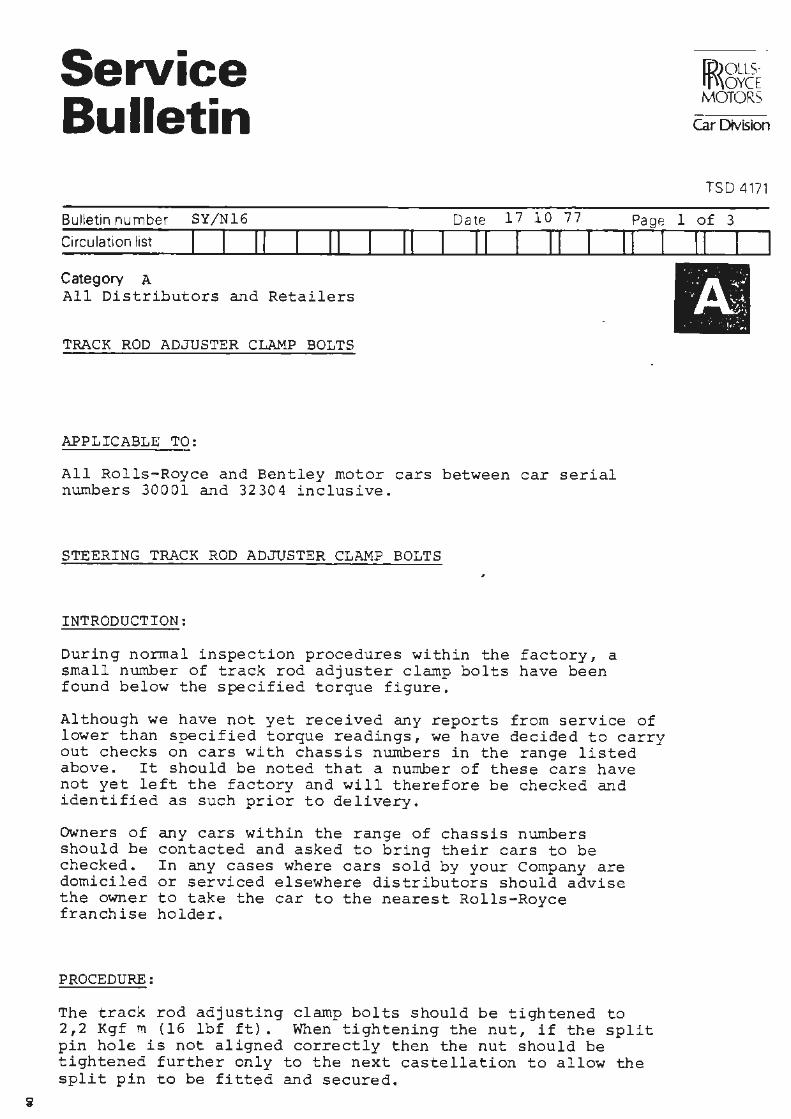
Service Bulletin
i IR{8~E I MOTORS
Car Division
TSD 4171
Bulletin number SY/Nl6 Date 17 10 77 Page l of 3 Circulation list I I ! f 11 11 11 11
Category A All Distributors and Retailers
TRACK ROD ADJUSTER CLAMP BOLTS
APPLICABLE 'l'O:
All Rolls-Royce and Bentley motor cars between car serial numbers 30001 and 32304 inclusive.
STEERING TRACK ROD ADJUSTER CLAMP BOLTS
INTRODUCTION:
During normal inspection procedures within the factory, a small number of track rod adjuster clamp bolts have been found below the specified torque figure.
11 I
Although we have not yet received any reports from service of lower than specified torque readings, we have decided to carry out checks on cars with chassis numbers in the range listed above. It should be noted that a number of these cars have not yet left the factory and will therefore be checked and identified as such prior to delivery.
Owners of should be checked. domiciled the owner franchise
PROCEDURE:
any cars within the range of chassis numbers contacted and asked to bring their cars to be In any cases where cars sold by your Company are or serviced elsewhere distributors should advise to take the car to the nearest Rolls-Royce holder.
The track rod adjusting clamp bolts should be tightened to 2,2 Kgf m (16 lbf ft). When tightening the nut, if the split pin hole is not aligned correctly then the nut should be tightened further only to the next castellation to allow the split pin to be fitted and secured.
I I I
II
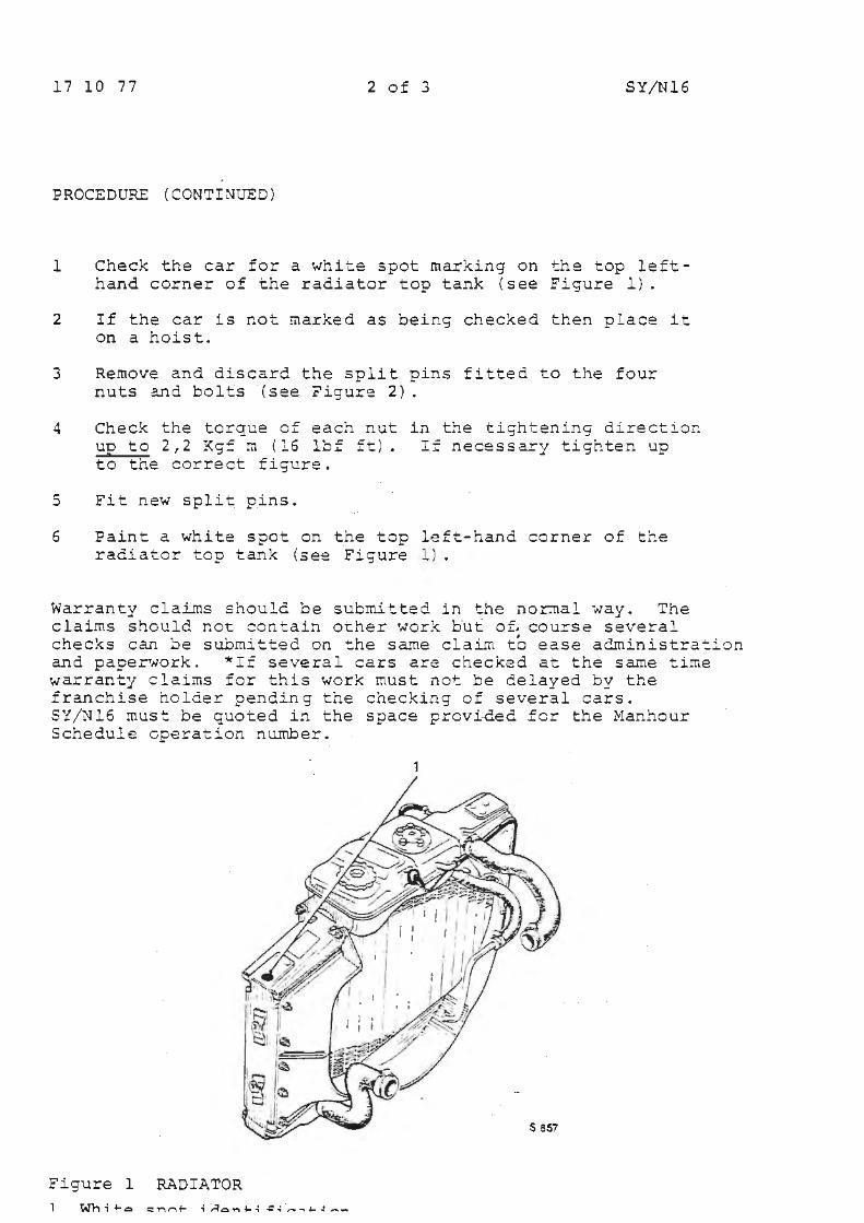
17 10 77 2 of 3 SY/Nl6
PROCEDURE {CONTINUED)
l Check the car for a white spot marking on the top lefthand corner of the radiator top tank {see Figure 1).
2 If the car is not marked as being checked then place it on a hoist.
3 Remove and discard the split pins fitted to the four nuts and bolts {see Figure 2).
4 Check the torque cf each n~t in the tightening directio~ uo to 2,2 Kg= m {16 lbf ft). I£ necessary tighten up to the correct figure.
5 Fit new split pins.
6 Paint a white spot on the top left-hand corner of t~e radiator top tank {se~ Figure l).
Warranty claL~s should be submitted in the nor.nal #ay. The claims should r.ot con~ain other work but 0£ course several checks can be submitted on ~he same claim to ease adroinistra~ion and paperNork. *If several cars are checked at the same time warranty claims for this work must not be delayed by the franchise holder pending the checking of several cars. SY/Nl6 must be quoted in the space provided fer the Manhour Schedule operation nu.m.ber.
1
Figure 1 RADIATOR

17 10 77 3 of 3
.. . -;,-. ....... -~ ... . 5
Figure 2 - TRACK ROD ADJUSTER CLAMP 30LT
1 Steering rack mounting feet
2 Adjuster clamp bolts
3 Track roe. ( inner)
4 Pinion housing
5 Track rod adjuster
6 Hydraulic pipework.
TIME ALLOWED:
To carry out check SY/Nl6 - 0.3 hours.
\ \
\ 'i
SY/Nl6
.-: .. ' . : .. S SS7
I Service Bulletins
Chapter P ~ Torqu~ Tightening Figures
I Service Bulletins
Chapter Q
~ Exhau~ System
I Service Bulletins
Chapter R
~ Wheel$ and Tyres
JR{&~E MOTORS
Service Bulletin CarDMsion
TSO 4171
Bulletin number SY/R35 Circu4ation list f I f I II
Date 5 10 76 Pa ge 1 of 3
Category C
TO ALL DISTRIBUTORS AND RETAILERS IN THE UNITED KINGDOM
II II I II
TYRE/WHEEL ASSEMBLY VIBRATION PROBLEMS - DUNLOP TYRES ONLY
II I 11 I
~ APPLICABLE TO: ~ i All Rolls-Royce Silver Shadow, Corniche and Camargue cars, ! and all Bentley T Series and Corniche cars. C7I
I ! i INTRODUCTION: I> j When vibration problems with tyre/wheel assemblies are encountered @) and normal corrective actions have proved to be unsatisfactory
the Dunlop Tyre Customer Organisation offer a tyre/wheel assembly harmonisation service. This service is available on an appointment basis only and may be chargeable. These charges will not be accepted under Rolls-Royce Motors Warranty • . The chart shown on page 2 indicates the nearest Dunlop Depot Service Department to your area.
Bly/MB
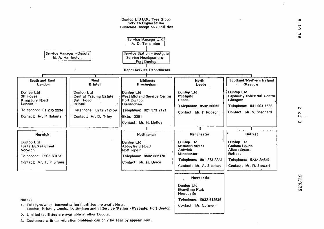
Dunlop Ltd U.K. Tyre Group Service Organisation
Customer Reception Facllltles
Service Manager U.K. A. D. T empleton
Service Manager w Depots M. A. Harrington .
Service Stal ion - Westgate Service Headquarters
Forl Dunlo
• South and East
London
Dunlop Ltd SP House Kingsbury Road London
Telephone: 01 205 2234
Contact: Mr. P Roberts ·
Norwich
Dunlop Ltd 43/ 47 Barker Street Norwich
Telephone: 0603 60481
Contact: Mr. T. Plummer
Notes:
• West
Bristol
Depot Service Departments I
• Midlands
Birmingham
Dunlop Ltd Ountop Ltd Central Trading Estate West Midland Service Centre Bath Road Fort Dunlop Bristoi • Birmingham
Telephone: 0272 712489. Telephone: 021 373 2121
Contact: Mr. O. TUey Exln: 3381
Contact: Mr. H. MuUoy
I
Nottingham
Dunlop Ltd · Abbeylield Road Nottingham
Telephone: 0602 862176
Contact: Mr. A. Byron
1. Full tyre/wheal harmonisation facilities .ire available at London, Bristol, Leed::., Nottingham and al Service Station - Westgate, Fort Dunlop.
2. Lunlled facilities are ava1latJle at other Depots.
3, Customers wilh car vibration problems can onlv be seen by appointment.
I
North Leeds
Dunlop Ltd Westgate Leeds
Tatephone: 0532 30033
Contact: Mr. F Robson
I
Manchester
Dunlop Ltd Mathews Street Ardwlck Manchester
Telephone: 061 273 3361
Contact: Mr. A. Stephen
I
Newcastle
Dunlop Lld Brandl ing Park Newcaslle
Telephone: 0632 813826
Contact: Mr. L. Spurr
I
ScoUand/Notlhern Ireland Glasgow
Dunfop Ltd Clydeway lnduslrlat Centre Glasgow
Telephone: 041 204 1586·
Contact: Mr. S. Shepherd
I
Belfast
Dunlop Ltd Graham Houso Albert SQuare Belfast
Telephone: 0232 35539
Contact: Mr. R. Stewart
Vl
.... 0
-.J O'\
0 HI
w
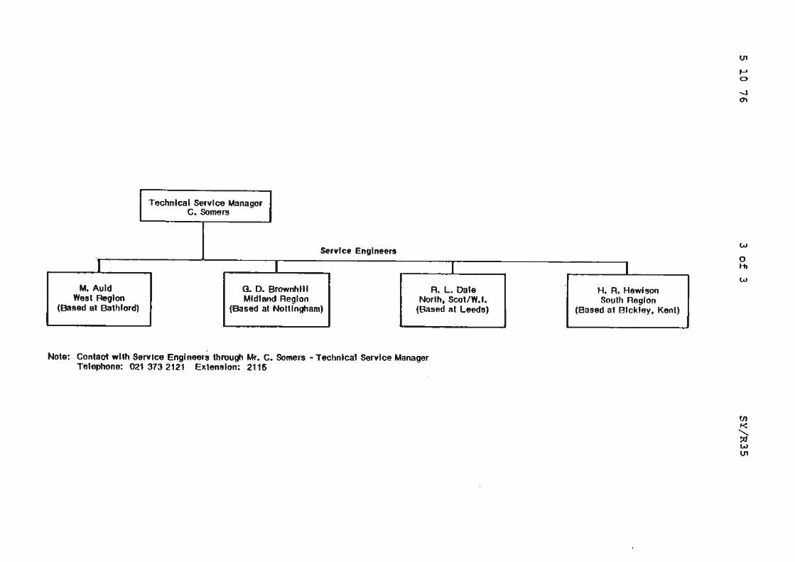
Technical SefVloo Manager c. Somers
Servfce Engineers
I I I M, Auld G. D. BrownhUI R. L. Dale
West RegJon Midland Region North, Scotlw.,. (Based at Bathford) {Based at Nottingham) (Based at Leeds)
Note: Contact wllh Service Engineers through Mr. C. Somers - Techntca1 Service Manager Telephone: 021 373 2121 Extension: 2115
I
H. R. Hewison South Region
(Based at Bick fey. Kent)
w
0 H,
w
Service Bulletin
Bulletin number SY/R36
Circulation list I I 11
Category C
TYRE PRESSURES
APPLICABLE TO:
Date
f I II 11
i ID)OLLS·
I ft'\OYCE I MOTORS
Car Division
TSD4171
7 10 77 Pa ge l of 2
II II I II
All Rolls-Royce Silver Shadow II, Carnargue and Corniche cars, Bentley T2 and Corniche cars and Rolls-Royce Silver Wraith II cars.
DESCRIPTION:
It is the purpose of this bulletin to stress the importance of correct tyre pressures to gain the rnaxirnwn possible advantage from t.~e rack and pinion steering and other.suspension changes.
The following table gives the correct tyre pressures and it is of the utmost importance ~~at they are strictly adhered to. It should also be noted that tyre pressures should only be checked wi t.11 11 cold" tyres.
Hly/DC

N
4-1 0
N
Market Rolls-Royce Camarguc Rolls-Royce and Benlley Cornicht,
Rolls-Royce Silver Wraith II without tlivision
Rolls-Royce Silver Wraith II with division
Rolls-Royce Silver Shadow 11 anti Bentley T2
USA. and Canada
Japan an<I Australia
All counlries other lhan al>ove
front lyres * 1. 7kg/sq Clll (2411,/sq in)
* 1, 7kiJ/sq cm (2411>/sQ in)
0 2.1 ky/sq cm (3011.>/sq in)
* l, 7kn/sq cm (2411>/sq in)
0 2, lky/sq cm {301b/sq in)
neur lyres 2,0kg/sq cm {281b/sq in)
2,0ky/sq Clll
(281l>/sq i11)
2.4ky/sq cm (3411..llSf) i11)
2.0kg/sq cm (281b/sq in)
2.4k!JISq cm (341b/sq in)
fronl lyms Re11r lyres 1, 7kg/sq cm 2,0kg/sq cm (2/llb/sq in) {2811,/sq in)
l. 7ku/sq cm 2,0k9/sq Clll
(2'1111/sq in) (281h/sq in)
2, 1ku/sq cm 2. 41<{1/!l<) Clll
(301h/sq in) (341h/sq in)
1. 7kgls<J cm 2.0kg/sq cm {241b/sq in) (281h/sq in)
2.1 kg/sq r;m 2.'lkg/sq cm {3011>/sq in) (341hls<1 in)
Front tyres 1, 7kg/ S(I Clll
(241b/sq iu)
l. 7kt,I S<I cm (2411,/sq in)
2,01<9/s<1 Clll
(2,0lh/sri in)
l, 7kg/sq Clll
{241h/sq in)
2, lkg/sq cm IJOlldsq inl
Rear tyrns Front tyres 2.0kg/sq cm (2811>/sq in)
2.0kg/sq cm l ,8kg/sq cm !281h/sq in) (21:ilh/sq in)
2.25ko/sq cm 2.lkg/sq cm (321b/sq in) (301h/sq in)
2.0kg/sq cm 1, 71<.!J/Sq COi
{2811>/sq in) (2411>/sq in)
2,'lkg/sq Clll 2. lkg/sq cm 13411.1/sq in) (301b/sq in)
Rear tyres
2,2t;kg/s11 cm (321bls<1 in)
2.5k!)/sq cm {3611.>/sq in)
2.1 kg/sq cm (3011>/sq in)
2.!Jkg/sq Clll
(361b/sq in)
Front tyres 1,7kg/sq cm {2411,/sq in)
1. 7k9/sq cm {241h/s11 in)
2.0kg/sq cm (28lbls<1 in)
l.ll<n/s,1 cm (241h/sq in)
2. l k!)lsq cm {301b/sq in}
* Speeds ur) to l80knilllf (110,nph) wilh up lo 5 occur>arrls in tho Silver Shadow II and Silver Wrailh II Hml 4 occupants in Cornichc and Camarguc and 113.5kns (2501bs) of luggauti.
0 for sustained speeds al>ove 180krn/hr (110111ph) wilh up to 5 occupa111s in the Silver Shadow II and Silver Wraith II and 4 occupants in Cornichc and Camaruue and 113.5kgs (25011.>s) of lum1aue.
Rear tyres 2,0kg/sq cm (281b/sq in)
2. Okg/ sq Clll
(281b/sq in)
2.25kg/sq cm (3211.>/sq in)
2,0kg/sq cm (2811.>/sq io)
2,4kg/sq cm (341h/sq ill)
Service Bulletin
Bulletin number SY/R37
Circulation list I ! 11
Category C
II
ALL DISTRIBUTORS AND RETAILERS
MICHELIN WIDE X HR70-15 TYRES
APPLICABLE TO:
II Date 29 8 77
I 11 I II I Pa ge
11 I
All Rolls-Royce and Bentley motor cars from the following car serial numbers.
Four door saloon Long wheelbase Corniche saloon Cor niche convertible -Camargue
INTRODUCTION:
SRC 18269 and onwards. LRC 19581 and onwards . CRC 18680 and onwards .
DRC 18678 and onwards . JRD 19094 and onwards .
(V)OLLSrf'\OYCE MOTORS
Car Division
TSO 4171
J o f 2 11 I I
Motor cars currently leaving the factory on direct export to North America, are being fitted with Michelin Wide X HR70-15 tyres.
The tyre is of similar construction and hence is compatible with the Michelin Wide X HR70-15 tyre currently available in North America. The tyre is not compatible with Dunlop HR70 HR15, or Firestone HR70 HRlS tyres previously fitted. It is therefore recommended that, in the case of fitting Michelin Wide X HR70-15 tyres as replacements for previous tyres, they are fitted in sets of five.
The tyre must not , under any circumstances be fitted to any motor cars o ther than those f or use in North Ameri ca.
The radial force variation low spot colour on the Michelin tyre is green and when fitting, the spot should be fitted adjacent to the high spot marked with the letter 'H' on the wheel rim.

29 8 77 2 of 2
TYRE PRESSURES:
Four door saloon Long wheelbase without division Corniche saloon Corniche convertible Camargue
Hly/SW
FRONT
1.69 kg/sq.cm. (24 lb/sq.in.)
SY/R37
REAR
1.97 kg/sq.cm. (28 lb/sq. in.)
Service Bulletin
Bulletin number
Circulation list
Category c
FORCE VARIATION MARKING - AVON TYRES
APPLICABLE TO:
All Rolls-Royce Caraargue, Corniche, Silver Wraith II and Silver Shadow motor cars.
All Bentley Corniche and T series cars.
INTRODUCTION:
Avon tyres will shortly be changing the colour of the marking which indicates the force variation low spot on radial-ply tyres.
DESCRIPTION:
All recommended radial-ply tyres for the above motor cars are marked with a red spot to indicate the force variation low spot of the tyre. Avon tyres supplied for service replacements may be marked with a green spot instead of a red one. When fitting the tyre to a wheel rim the red or green spot must be aligned with the letter 'H' stamped in the well of the rim to ensure optimum harmonisation of the wheel tyre assembly.
Hly
ID)OLLS· rf\\OYCE MOTORS
Car Division
TSD4171
Service Bulletin
ID)OLLS· rf"\OYCE MOTORS
Car Division
TS D 4 i71
Bulletin number SY/R39
Circulation 11st j j Pa gf; 1 of 2
" Oatf: 2 5 78
I ·e :J Ill
£ 0 ::z 8
II 11 11 I 11 11 I 11
Category C
ALL FRANCHISE HOLDERS OTHER THAN THOSE IN NORTH AMERICA, SOUTH AMERICA AND SOUTH AFRICA
AVON 235/70 HR15 R-R TURBOSTEEL 70 101H TYRE
APPLICABLE TO
All Rolls-Royce and Bentley motor cars from the following car serial numbers.
Four door saloon Long wheelbase saloon Corniche Camargue
SRC 18269 and onwards LRH 19577 and onwards DRH 18563 and onwards JRH 14674 and onwards
£ INTRODUCTION .!!! £ From the following car serial nW!lbers, cars leaving the factory © equipped with Avon tyres, will have a new type of tyre fitted.
Silver Shadow II and Bentley T2 Silver Wraith II Corniche Camargue
SBH 33712 and onwards LR.X 33017 and onwards DRH 32491 and onwards JRX 32035 and onwards
This new tyre is suitable for use in all countries other than North America, South America and south Africa.
DESCRIPTION
The new tyre is of steel braced construction and is an all round improvement over its textile equivalent.
The main advantages are:
1 Improved stability. 2 More responsive handling. 3 Improved cornering power with increased grip on wet surfaces. 4 Potential improvement in tyre life.
2-5-78 2 of 2 SY/R39
The new tyres are marked "R-R TURBOSTEEL 70 235/70 HRlS 101H11•
The marking 'lOlH' conforms with the new European standards. '101' is the load index referring to the maximum tyre loading and the 'H' mark confirms the speed rating of 130 mph.
FITTING INSTRUCTIONS
The radial force variation low spot colour on the Avon Turbosteel 70 tyre is red. When fitting these tyres the red spot should be aligned with the highest point of the wheel, marked with the letter 'H' on the wheel rim.
The new tyre may be used as a service replacement on all cars which were equipped with either HR70 HR15 or 235/70 HRlS marked tyres as original equipment; i.e. all cars after the car serial numbers listed at the beginning of this bulletin.
As the tyre is of steel braced construction and not textile it is recommended that they are fitted in car sets. However, if for some reason this is not possible the legal requirement concerning the mixing of tyres should be considered.
'TYRES OF TEXTILE CONSTRUCTION MAY BE MIXED WITH TYRES OF STEEL BRACED CONSTRUCTION ONLY IF THEY ARE FITTED IN PAIRS, w'"ITH THE PAIR OF STEEL BRACED TYRES FITTED TO THE REAR WHEELS.'
It should be noted that if two different types of tyre were fitted, then the spare tyre would be suitable for use on one pair of wheels only.
TYRE PRESSURES
Tyre pressures remain unchanged.
Hly/SW
co B; .. ~
! ·e J ~ 1:? 0 :::: <IJ y >-0 a: I
(0
£ @)
Service Bulletin
Bulletin number SY
Circulation list
Category c
ALL FRANCHISE HOLDERS
DUNLOP RAYON/RAYON TYRES
APPLICABLE TO: •
ID>OLLS- i rt)\OYCE MOTORS
Car Division
TSD4171
All Rolls-Royce and Bentley motor cars from the following car serial nwnbers.
Four door saloon - SRC 18269 and onwards
Long wheelbase saloon - LRH 19577 and onwards
Corniche Saloon CRE 18564 and onwards
Corniche Convertible - DRH 18563 and onwards
Camargue - JP.H 14674 and onwards
DESCRIPTION
The Dunlop HR70 HR15 SP Sport Formula '70' T/L tyres have previously been subject to possible 'flatting' problems. In order to eliminate this potential problem the same tyre is now being manufactured with a 'rayon' carcase replacing the previous 'nylon• carcase. The tread pattern of the tyre remains the same. The only visible changes to the tyre are:
1) The word 'nylon' on the tyre sidewall is replaced with the word 'rayon' , and
2) The outer sidewall now has a raised rib instead of one which is undercut or inset.
The new tyre has been introduced at car serial number SRX 33310.
This tyre may be fitted on all the above motor cars as a direct service replacement for the nylon carcased tyre, but, due to the different sidewall appearance it may be desirable to fit the tyre in car sets. However, no adverse results would arise if nylon tyres and rayon tyres are fitted on the same axle.

18 4 78 2 of 2 SY/R40
The radial force variation low spot colour on the new tyre is red and when fitting, the spot should be aligned with the highest point of the wheel, marked with the letter 'H' on the wheel rim.
Tyre pressures remain unchanged.
Hly/SW

I Service Bulletins
Chapter S
~ Body
~
Service Bulletin
Bulletin number
Circi..:lation 11st
Category
ALL DEALERS IN USA AND CANADA
FLOOR INSULATION PAD
APPLICABLE TO:
(R{~E MOTORS
CarDMsion
TSD4171
All Rolls-Royce Silver Shadow and Corniche cars frorn the following Car Serial Numbers.
Silver Shadow saloon - SRD 20378 to 22427 Long Wheelbase saloon - LRD 20592 to 22437 Corniche - CRD 20171 to 22385
- DRD 20176 to 22322
! For full details refer to rear of this Bulletin • ..J
~ 0
j PROCEDUPE:
0 CI
©
1 . Disconnect battery.
2 . Remove the three carpet clips from floor (see Fig. 1).
3 . Securely staple or stitch the Velcro to carpets {see Fig. 1).
4. Raise car on hydraulic ramp (hoist).
5. In order to enable the floor insulation pad to be fitted correctly on cars prior to Car Serial Numbers SRD 22118 and LRD 22073 the brake pipe connector block must be slightly repositioned. Figure 2 gives details of the re-location of this block. DO NOT DISCONNECT THE BRAKE PIPES since this will result in the need to bleed the system.
6. Remove the exhaust clamp and modify as Figure 2.
7. Offer up to the floor the thick insulation pad, the thin insulation pad and the alloy cover. Ensure that the insulation pads are encapsulated in the cover and that the cover~ forward-flange abuts the crossmember. Figure 2 shows the cover in position.
8. Drill and secure the cover with the screws provided. It may be found necessary to slacken and move the grass shield round whilst drilling the floor.
9. Fit the clamp previously removed.
10. Fit the carpets to the car and connect the battery.
10 3 76 2 of 8
TIME ALLOWED
Total time allowed - 1. 5 hours.
The kit RH 2649 contains the following items:
1 off l off 1 off 10 off l off 1 off
Alloy shield Insulator Insulator Screw Velcro 'hook' Velcro • loop'
- UR 19830 UR 19831 UR 19832
- UA 9487/Z UW 15497 UW 1549 8
SY/S30 Iss 2
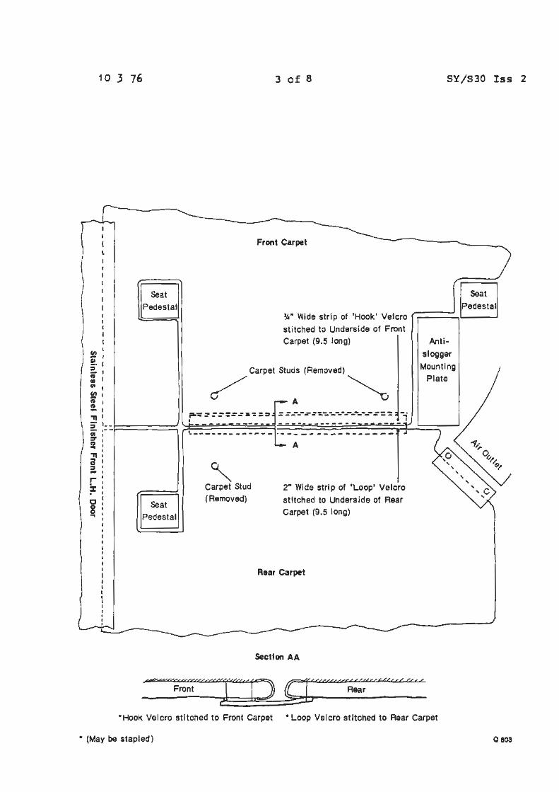
Cl) -!. = • Ill (It
1 O .3 76
t
Seat Pedestal
~· l'D !. '11
:!. Ill ':I' l'D .. '11 a ::, -r % . C 8 ...
I
I I I •• ,--
Seat Pedestal
3 of 8
Front Carpet
~· Wide strip of 'Hook' Velcro sti tched to Underside of Front Carpet (9.5 long)
Carpet Studs (Removed)
/ A ~ ~,:::::,:,:,.:a,:::, - ---.,,.----,- ------- --i I I
·------------- a---------------- j
~ Carpet Stud (Removed)
A
2" Wide strip of 'Loop' Velcro
stitched to Underside of Rear Carpet (9.5 long)
Rear Carpet
Section AA
SY/S30 Iss 2
Anti
slogger Mounting
Plate
Seat Pedestal
·Hook Velcro stitched to Front Carpet • Loop Velcro stitched to Rear Carpet
• (May be stapled) o 803
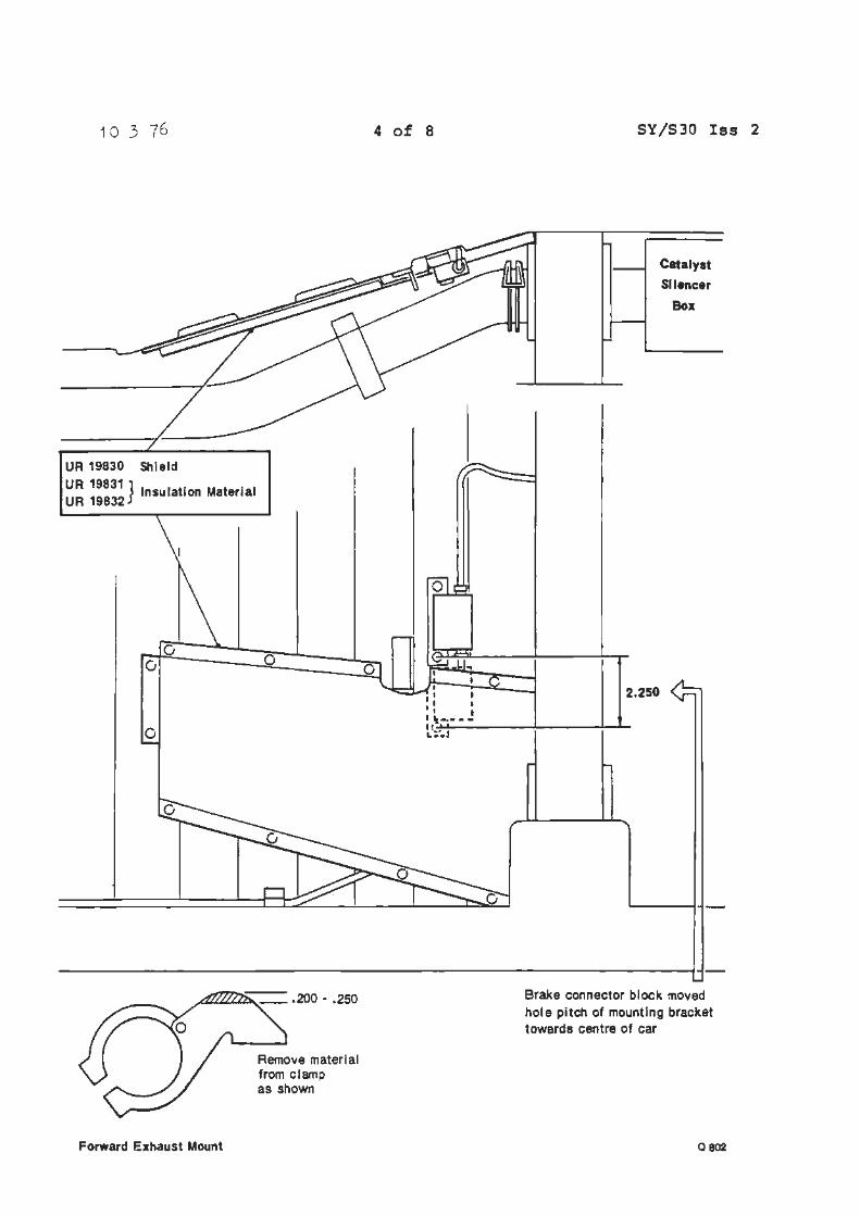
1 O 3 76
UR 19830 Shield
UR 19831 } I I t· M t . I UR 19832
nsu a 10n a eria
0
Forward Exhaust Mount
0
Remove material from clamp as shown
4 of 8
I I I I I l
I t •1i----L!:~J
SY/S30 Iss 2
Catalyst SIiencer
Box
2.250
Brake connector block moved hole pitch of mounting bracket towards centre of car
0802
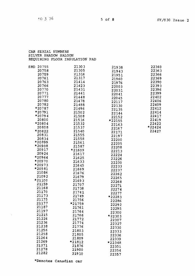
10 3 76 5 of 8 SY/S30 Issue 2
CAR SERIAL NUMBERS SILVER SHADOW SALOON REQUIRING FLOOR INSULATION PAD
SRD 20755 21303 21938 22360 20758 21305 21943 22363 20759 21316 21951 22366 20761 21317 21960 22369 20763 21414 21976 22390 20766 21423 22003 22393 20770 21431 22031 22396 20771 21441 22041 22399 20777 21448 22045 22402 20780 21478 22117 22406 20782 21488 22130 22409
* 207 87 21496 22135 22412 *20791 21502 22144 22414 *20794 21508 22152 22417
20800 21516 *22155 22419 *20804 21532 22163 22422
20808 21537 22167 *22424 *20822 21540 22171 22427
20831 21555 22197 20834 21558 22200
*20899 21561 22205 *20908 21587 22208
20917 '* 21609 22213 20924 21617 22224
*20964 21625 22226 *20970 21633 22230 *20973 21645 22233 *20981 21669 22237
21086 21676 22262 21092 21679 22265
* 21100 21693 22268 21159 21707 22271 21168 21738 22274 21.170 21741 22277 21173 21749 *22283 21175 21756 22286 21177 *21759 22292 21187 21761 22295 21197 21764 22300 21215 21766 * 2230 3 21226 21772 22307 21236 21774 22327 21238 21776 22330 21256 21803 22333 21258 21805 22336 21264 21809 22339 21269 *21812 *22348 21271 21876 22351 21278 21900 22354 21282 21910 22357
*Denotes Canadian car
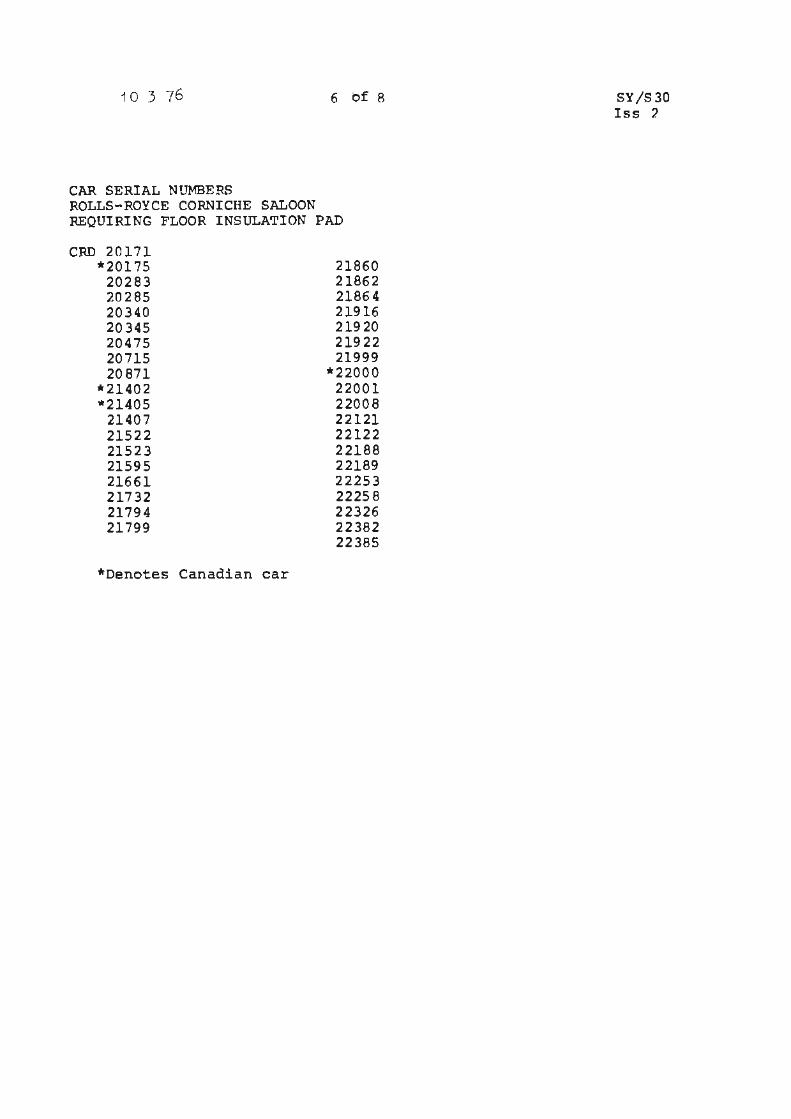
1 O 3 76 6 of s
CAR SERIAL NUMBERS ROLLS-ROYCE CORNICHE SALOON :REQUIRING FLOOR INSULATION PAD
CRD 20171 *20175
20283 20285 20340 20345 20475 20715 20871
*21402 *21405
21407 21522 21523 21595 21661 21732 21794 21799
*Denotes Canadian car
21860 21862 21864 21916 21920 21922 21999
*22000 22001 22008 22121 22122 22188 22189 22253 22258 22326 22382 22385
SY/S30 Iss 7.
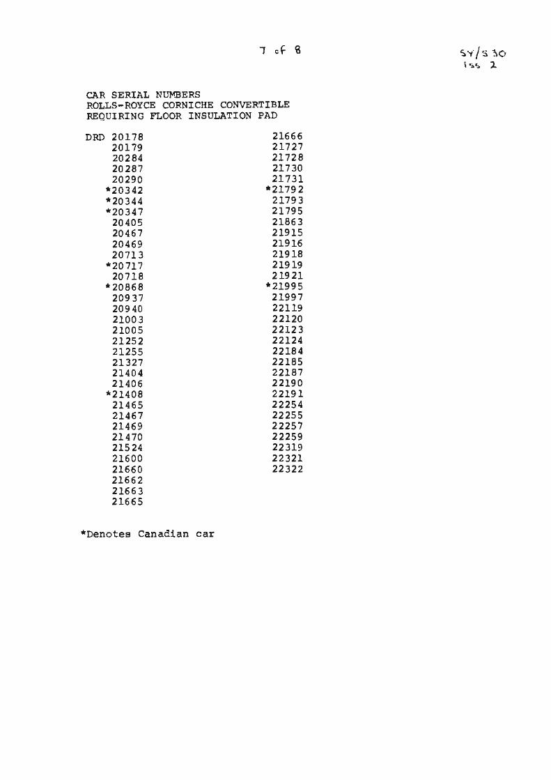
CAR SERIAL NUMBERS ROLLS-ROYCE CORNICHE CONVERTIBLE REQUIRING FLOOR INSULATION PAD
DRD 20178 20179 20284 20287 20290
*20342 *20344 *20347
20405 20467 20469 20713
*20 717 20718
* 20868 20937 20940 21003 21005 21252 21255 21327 21404 21406
*214 08 21465 21467 21469 21470 21524 21600 21660 21662 21663 21665
*Denotes Canadian car
21666 21727 21728 21730 21731
*21792 21793 21795 21863 21915 21916 21918 21919 21921
*21995 21997 22119 22120 22123 22124 22184 22185 22187 22190 22191 22254 22255 22257 22259 22319 22321 22322
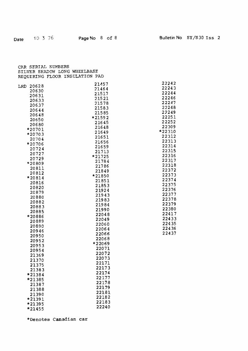
Date 10 3 76 Page No 8 of 6
CAR SERIAL NUMBERS SILVER SHADOW LONG WHEELBASE REQUIRING FLOOR INSULATION PAD
LRD 20628 20630 20631 20633 20637 20644 20648 20650 20680
*20701 *2070 3
20704 *20706
20724 20727 20729
*20809 20811 20812
*20814 20816 20820 20879 20880 20882 20883 20885
*20886 20889 20890 20946 20950 20952 20953 20954 21369 21370 21375 21383
*21384 *21385
21387 21388 21390
*21391 *21395 *21455
*Denotes Canadian car
21~57 21464 21517 21521 21578 21583 21585
*21592 21645 21648 21649 21651 21656 21659 21713
*21725 21784 21786 21849
*21850 21851 21853 21924 21943 21983 21984 21990 22048 22049 22060 22064 22066 22068
*22069 22071 22072 22073 22171 22173 22174 22177 22178 22179 22181 22182 22183 22240
Bulletin No SY/S30 Iss 2
22242 22243 22244 22246 22247 22248 22249 22251 22252 22309
*22310 22312 22313 22314 22315 22316 22317 22318 22372 22373 22374 22375 22376 22377 22378 22379 22380 22417 22433 22435 22436 22437
Service Bulletin
Bulletin number SY7'S3t
Circulation 11st 11
Category C
11
ALL DISTRIBUTORS AND RETAILERS
PAINT FILM THICKNESS
Date 21 4 ,~
Page
11 II 11 11 I
~ APPLICABLE TO: ~ "O
~ e :J "' g 0 ::t
All Rolls-Royce and Bentley motor cars painted with (FTA) FULL THERMOPLASTIC ACRYLIC PAINT,
l DESCRIPT'ION:
"' ~ This Service Bulletin is issued to inform you of the correct ® paint film thickness control procedures to adopt when re
finishing with (FTA) FULL THERMOPLASTIC ACRYLIC PAINT.
It is an essential requirement that the thickness of the (FTA) Full Thermoplastic Acrylic paint colour coat is restricted to a maximwn of 0,1016 mm.(0,004 in.).
It is therefore important that as much as possible of the original paintwork thickness is removed before the application of further quantities of new colour.
This is to ensure that the total colour paint thickness remains below the maximum of 0,1016 mm.(0.004 in.) and that the maximum service durability is maintained.
Before carrying out any paintwork rectification work always consult Service Bulletin SY/S19 Issue 3. The Service Bulletin to consult for Carnargue motor cars is SY/S28.
ECk/MH
ID>OLLS-11'\0YCE MOTORS
Car Division
TSO 4171
t of 1
11
Service Bulletin
Bulletin number
Circdation 11st
Category c
11 II
TO ALL DISTRIBUTORS AND RETAILERS
INTERCHANGEABLE THINNERS
APPLICABLE TO:
Date 3 3 7f II I
Page
II I
All Rolls-Royce Camargue, Corniche and Silver Shadow cars, ~ and all Bentley Corniche and 'T' Series motor cars.
Q a
DESCRIPTION:
When ordering modified cellulose thinners, part number 851-1141, it is possible to be supplied with modified cellulose thinners, part number 851-732.
Either of the above mentioned thinners can be used when a modified cellulose thinners appertaining to the MlSl or the M062 is called for.
For details of thinners to use with paint material consult the following Service Bulletins:
Carnargue - SY/S28 Corniche - SY/S34 Silver Shadow - SY/S37
ECk/MH
IR{g~E MOTORS
Car Division
TSD 4171
1 of J n I
Service Bulletin
Bulletin n·umber SY /S 35
Circulation list l l l I Category c
Date
11 I
TO ALL DISTRIBl1TORS AND RETAILF:RS
4 2 7f.
II I II
FRONT AND REAR SCREEN REMOVAL AND FITTING
APPLICABLE TO:
All Rolls-Royce Camargue cars.
DESCRIPTION:
Paq,s
II
~ ft'~OYCE I MOTORS I
Car Division
1 of 12
II I
This Service Bulletin lists the procedures for re~oving and fitting front or rear screens. Both screens are sealen. and retained with Bostic Solbit Thermoelectric sealing strip. This sealing compound has a shelf life of approximately six months and is available from Rolls-Royce Motors Limited, (KIT NU~IBER RH 8975).
This kit includes a length of Solbit, a length of cutting wire, a bottle of Bostic primer and two rubber spacers.
The Solbit sealing strip is circular in section, supplied in lengths, sufficient to seal either a windscreen or a rear winnow.
A wire running through the centre of the sealing strip enables the Solbit to be heated during the fitting procedure by passing an electrical current through it. The power required to heat the Solbit correctly is 24 volts at 11 amps and a suitable transformer should be used.
If a transformer capable of aiving the correct current is not available, two fully charged 12 volt batteries connected in series (ie •+• to'-') may be used instead..
NOTE Always use the specified power supply to heat the Solbit sealing strip as the heating times given in the followin~ fitting procedures are based on this supply. Also a lower current will be insufficient to effect a satisfactory curing of the ~olbit strip.
PROCEDURES:
WINDSCREEN TO REMOVE
1. Disconnect the battery.
2. Protect the paintwork in the vicinity of the screen with thick felt or similar.
4 2 76 2 of 12 SY/S35
3. Remove the wiper arms an<'l blades.
4. Pernove the sun visors and interior ~irror.
5. Pemove 'A' post trim panels from each sine of screen.
These panels are retaine~ by a screw, cup washer an~ a spring clip.
6. Pemove the four screws securing the .front roof finishf'r panel ahove the screen; reMove the pane].
NOTE To qa5.n access to thE> rear securing scre1;1 of ~ach panel it will be necessary to first oetach the fron~ encs of the rear quarter upper trirn p2.nels frorri t.he cant .. rail; these panels heinq n~tainec:'l with sprino. clins.
7. Remove the facia top roll and the deJl'l.ister ori lJ_e/windscreen lower finisher panel asse~blv: (s~e Bulletin SY/s~q).
8. Using a screwc'lriver, carefully lever t.1-ie chromed moulcec. finisher and seal out of the aperture; start at one corner, then progressively lift the combined finisher an0 seal out of the recess. If the chro~ed finisher lifts out of the seal during this operation, it will be necessary to first remove the finisher and then the seal.
Care must be exercisec to avoid aarnc1ginq the pa:tntuork, screen or chromed finisher.
9. From insi~e the car, carefully detach the finisher strip from the upper and side flanges of. the screen aperture.
10. Be fore the qlass can be reJT1.oved it wi 11 be necesRary to bre a}: the Solbi t seal as follows:
Fro~ insid~ t~e car, cut or pierce a hole throuoh the Solbi t seal (see Fig. 1). Threaa one end of the wire provided in the kit through the hole in the seal. Jltt.nch a small piece of wood to each end of the wire to a<:'.t as a handle (see Fig. 1), or alternatively, form a handle bv threading the wire through a s~all hole orillea in the end of an old screwdriver or length of metal bar. With an assistant holding the interior handle such that the wire inside the car is lying along the line of the seal, firmly pull the exterior handle so that the wire is drawn along between the glass and the flanqe, cutting through the Solbit seal. Repeat this cuttinq action around the periphery of the glass until it is free. T~e long steady pulls other-wise the wire will break. When the cutting operation is almost complete the glass should be supported to prevent slipping.
4 2 76 3 of 12 SY/S35
NOTE To avoid darnaqe to the paintwork , kee.o the en<ls of tne wire as ciose as possible to the glass when cutting through the Solbit seal.
11. When the qlass is freed remove the windscreen.
12. Using a sharp knife, remove the old Solbit seal from the flange to ensure an even surface but take care to avoid damaging the paintwork.
WINDSCREEJ:1 - TO FIT
1. Remove all traces of dirt and sealing compoun0. fro~ aroun<l the screen aperture using Bostik Cleaner 6001,
2, Clean the sealing area on the inner face of the new screen glass with Bostik Cleaner ~001.
3. Apply Solhit Primer 1058 to the aperture flanges and to the nating surface of the windscreen; apply the Primer to a strip around approximately 9,5 ~~.the periphe ry of the glass.
4. Using masking tape, protect the are a of the paintwork at the left- hand corner of the scuttle where the exposed wlres will be during the heatinq of the Solbit.
5. Locate the screen in the correct vertical Position in the aperture. This is best done by placing two ~,5 mm. {n,375 inch) thick distance pieces on the bottom face of the aperture, some 23 cm (9 inches) inboard from each edge.
6. Locate the screen onto the 0is tance spacers then centrally position the winoscreen in the aperture. Adjust the thickness of the distance spacers if necessary until this condition is obtained. ( see Fiq. 2) •
7. Mar k the centre ooint of the glass and top flanqe using masking tape; this is to facilitate accurate re-location of the windscreen in the aperture when it is finally installed.
8. Remove the windscreen from the aperture.
9. Without removing the Solbit sealinq strip from its plastic container, expose the en0s of the wire running through the sealing strip and connect them to the 24 volt power source, (refer to Description - Solbit). Allow the current to pre-heat the sealing ~trip until it is sufficiently 'tacky' to adhere to the aperture flange, then disconnect the power source.
Do not overheat the Solbit as this will tend to make it difficult to handle.
NOTE The time required to pre-heat the Solhit seal will take between 15 and 90 seconds, dependant on the
4 2 76 4 of 12 SY/S35
temperature and age of the Solbit. If the Solbit fails to soften sufficiently durinq this pre-heating period, it will indicate that t.he Solbit seal has exceeded its useful shelf life. In this event discard the seal an<l begin the ~re-heatinq process again using a new Solbit sealina striP.
10. Starting at the lower left-hand corner of the screen aoerture, fit the Solbit strip around the entire apertur~ flange using light fin~er pressure only to locate the strip onto the flange. ·
Ensure that the sealina strip is positioned approxiMately 1,5 mm (0.625 in) from the inner eaqe of the aner.turP flange so that it will finish exactiy level wi~h the inner edge of the flan~e when the glass is pressea into position at a later stage in this fitting proce<lure.
11. 'C:'sing light finger pressure, level anc' Sl:'ooth the seal where the two ends join to eliminate any possible source of leaks.
Retain any superfluot1s Solbit compoi.1nd removed from the joint for future use.
12. Lift the windscreen onto the distance blocks on the lower flange of the body aperture then locate the glass precisely to its pre-marked position (refer to ~peration 7).
Do not apply pressure to the glass at this stage of the fitting procedure.
13. Connect the 24 volt supply to the ends of the wire running through the Solbit seal then insert the depth control blocks between the glass and the flange, suitably spaced around the periphery of the glass (see rig. 2). Allow the current to flow through the seal. Press the glass onto the Solbit until it comes into contact with the denth control ',locks; start by applying hand pressure at the centre and working outwards towards the pillars until the glass is sealed evenly on the blocks (see Fig 2).
The function of the denth control blocks is to ensure a satisfactory seal seatinq dimension. Suitable blocks can be produce<1 from wood or similar easily shaped material. Refer to Fig 2 which shows a depth control block in position ann the required glass to flange dimension: ensure that the glass seating ledge of the block does not intrude into the Solhit by more than 3,2 mrn (0.125 inJ.
4 2 76 5 of 12 SY/S35
14. Allow the current to flow throuqh the Solbit strip for between 1~ to 2 hours to effect cure of the seal then disconnect the prn··er supply fr0m the seal and c1llow thA glass to cool down.
15. When the glass has cooled, trim the enns of the ex~osed wire in the Solbit seal and fold them back l evel with the seal.
16. Remove t h e depth control blocks from arouno the winascreen and using supe rfluous Solhit compound which has undergone the heat treatment snecified in operation 14, fill in any s mall indentations in the Solbit seal c reate0 by the blocks.
17. From inside the car, trim and smooth the Solbit s~al until it finishes exactly level with the inne r e dge of the flange arouno the entire periphery of. the aperture.
A tirober or plastic spatula will faciliate this ooeration.
18. Remove the masking tape used to centralise the windscreen in the aperture then wipe off any excess Solhit from the exterior paintwork, and also from the body flanges and glass inside the car, using a cloth moistened with Rostik Cleaner 6001.
19. Clean the whole screen aperture recess ana also the periphery of the screen wj_th a clean cloth moistenea with Bostik Cleaner 6001 to remove any dirt or grea~e..
20. Pre-fit the moulded rubber seal to the exteri or of the screen aperture ann check for a satisfactory fit around entire periphery of the glass. Remove the seal froM the aperture, fit the chro~e~ finisher to the seal the n clean the rubber seal with Bostik Cleaner 6001 to remove all traces of dirt ano wax.
21. Clean the rnating area around the outer edge of the glass for the rubber face seal using Bostik Cleaner 6001.
22. Allow the cleaner to completely a ry then ap~ly Dunlop Adhesive S1240 to the face seal and to its mating surface on the windscreen glass. Apply the adhesive in an approximately 9,5 mro (0.375 in) wide &trip around the edge of the glass.
23. Allow between 10 and 30 minutes for the adhesive to become 'tacky' then locate the face seal to the glass, startinq and finishing at the centre of the upper edge of the qlass. Butt-joint the seal at the upper centre position, then press the seal firmly into positi on; remove any excess adhesive using Rostik Cleaner 6001,
4 2 76 6 of 12 SY/S35
24. Apply Dunlop Adhesive S1240 or a siMilar black Neoprene aahesive to the screen aperture arouna t~e entire periphery of the glass ana also to the moulded rubber seal; allow between 10 and 30 minutes for trie aohesive to become 'tacky 1 , then position the co~hine~ finisher an0 moulded seal to the aperture an(~ press the ~eal flrMlv into the recess surroundinq the glass.
The outer lio of the Moulded seal should seat evenly against the body panels ann the inner edge of the finisher should seat eventlv against the face seal rubber (see Fiq 3}. ·· ·
25. Trim the exposed edge of the face seal so thnt it is parallel to, but slightly ~nder the inner edge of the chroMed finisher ~oulding (see Fig. 3).
26. Test the screen for water leaks by applyinq water, under pressure, to the outside of the windscreen.
If the screen sealing is satisfactory, fit the rubber finisher seal to the upper and side flan9es of the screen aperture inside the car as follows.
27. Clean the bonding surf aces of the w.i..ndscreen flanaes inside the car and the finisher strip with Bostik Cleaner 6001~ allow the cleaner to dry.
28. Apply Boscoprene PriMer 9?.52 or a similar primer to the adhesive used in operation 24, to the bonding areas of the windscreen flanges only an<l allow one hour for the primer to dry.
29. Apply Boscoprene Adhesive 240?. (parts 1 and 2) or a similar black adhesive to the hondinq surfaces of the winc.screen flanges ano the finisher strip. Allow between 1n and 15 minutes for the adhesive to partly dry, then fit the finisher strip to the upper an~ side flanqes of the windscreen aperture (see Fig. 3); hand the seal by pressing it firmly to the flanges.
30. Trim the ends of the finisher strip to fit neatly into the lower corners of the windscreen aperture.
31. Finally, fit the interior trim panels surroundinq the windscreen by reversing the procedure given for their removal.
32. Reconnect the car battery.
4 2 76 7 of 12
:REAR WINDOW (rear screen) - To remove
l. Disconnect the battery.
SY/S 35
2. Cover the paintwork in the vicinity of the rear window to prevent possible damage .
3. Remove the rear seat cushion by sliqht1y rni~inq in a fo:n,ard direction, remove the four~ in . AF ~olts locate~ under the seat backrests and pull the seat backrests out in a downward direction, remove the two screws holding the centre arm rest to the rear seat cushion hack board, and pull the arm rest in a sliqhtly forward/cownwar~ position.
4. Remove the left and right-hand rear quarter trim panels (see Bulletin SY/S29).
5. Remove the four screws securing the sides of the trim panel situated above the rear windowi pull the panel downwaros to detach the four spring clips securing it to the roof bracket then remove the trim panel.
6. Remove the trim panel situatea below the rear window bv pulling the. panel towards the front of the car until the four spring clips, attached to the rear winnow hv pullinq the panel towards the front of the car until the four soring clips, attached to the rear of the panel are freea from the body.
A strip of metal or strona wire , bent at one en<l ,to forl"'1 a hook, will assist in removing the panel but care must be taken to avoid damaging the trim.
7. Using a screwdriver, c8refully prise the screen finisher and moulded rubber seal of the aperture; start at one corner of the finisher then progressively lift the finisher ano seal out of the recess until they are removed from the aperture. If the chromed finisher lifts out of the seal during removal it will be necessary to first remove the finisher and then the seal.
Take care during this operation to avoid damage to the paintwork, screen or finisher.
8. Disconnect the electrical leads to the rear window heater element at their 'bullet' type snap connectors then draw the cables through the two grollU!lets.
Both cable connectors are accessible from inside the luqqage compartment and are located one behind each hinge torsion bar assembly.
4 2 76 8 of 12 SY/S35
9. Carefully detach the rubber finisher seal from the flanges of the rear window aperture inside the cari remove the finisher strip.
10. The reRr window is sealed to the aperture flange by Solbit strip. To free the glass from the flange, follow the same procedure described previously to free the windscreen {refer to 'WINDSCREEN - To remove', Operation 10).
IMPORTANT When freeing the Solbit seal, take care to avoid damaging the two electrical cables to the rear window heater element.
11. When the qlass is freer't from the flange, care!ully remove the rear windcw from the aperture.
12. Using a sharp knife, remove t'.".e olo Solbi t seal from the flange to E:!nS'...:!:'e an even surface. fio not darnacre paint·· ~rork.
REAR WINDOW - To fit
To fit the rear win~ow, follow the same basic procedure already described for fitting the winrlscreen {refer to 'Windscreen -To fjt' Operations 1 t0 25) but note the following points:-
!. Prior to locating the qlass :l..n~c the Cclbit seal, relieve the seal locally on the low<;r flange in t\-ro places to allow the two rear winoow !:',eater cables to pass throu0'h the Solbit strip.
2. When fittin~ the rear window glass into the anerture (Operation 12 in the basic procedure), threa0 the two heater cables into the interior of the car ensuring that they are aligned with the relief slots in the Solbit seal.
3. After. fillinq in any small indentations in the Solhit seal (Operation 16 in the basic procedure}, check that the rear window heater cables are alignea with the two cut-outs in the inner lip of the aperture flange then plug any qa~s around the cables with su~erfluous Solbit compound.
NOTE Ensure that the Solbit cornpounc"I used to repair the seal has unoergone the heat treatment <lescribed in 0peration 14 of the basic procedure.
4. If the windscreen is sealing satisfactory after cornoletinq the basic procedure, fit the rubber finisher stri~ to the rear aperture flanges inside the car as follows.·
4 2 76 9 of 12 SY/S35
5. Clean the h.onding surface of the rear window anerturP. flanaes and the finisher strip with Bostik Cleaner ~nn1 allow the cleaner to dry.
6. Apply Boscolite Primer 9253 or a similar primer to th~ aahesive used in operation 8 to the banding areas of the rear window flanqes only and allow one hour for the primer to·dry.
7. If a new finisher seal is heinq fittea, cut the seal into two lengths; one length to fit the upper ana s i<'l.e flanges, one length to fit the lower f 1 ange. 1"i t re one corner only, then locate the mitred joint; clean up the joint as necessary to obtain a neat fit.
8. Apply Boscoprene Adhesive 2402 (Parts land 2) or a similar blac:Ji-. adhesive to the bonc!ing surfaces of the screen aperture flanges and the finisher strins; leave approxiITlately 12,7 cm (5 inJ. at the unmit.red end of the strips free from adhesive to allow cutting and fitting of the remaining joint.
9. Allow between 10 and 15 minutes for the adhesive to partly dry, then fit the finisher strips to the anerture flanges commencing at the mitred joint. Press the sealing strips firmly to the flanges.
10. Cut ana fit the mitre joint in the remaining corner of the aperture and seal the strips by reoeatina the process detailed in operations A and 9.
11. When the interior finisher strip is fitted satisfactory connect the two rear win~ow heater leads at their cable connectors and fit the trim panels surrounding the rear window by reversing t.he procedure given for their reMoval.
12. Reconnect the car batterv.
ECk/MH
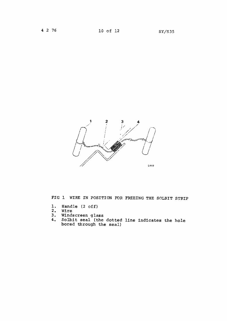
4 2 76 10 of 12 SY/S35
1 . 2 I
I I
0869
FIG 1 WIRE IN POSITION FOR FREEING THE SOLBIT STRIP
1. Handle (2 off) 2. Wire 3 . Windscreen glass 4. Solbit seal (the dotted line indicates the hole
bored through the seal)
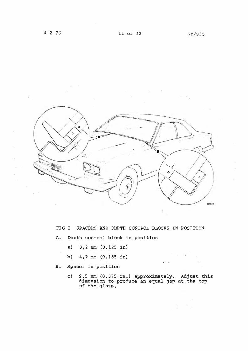
4 2 76 11 o f 1 2 SY/S 35
FIG 2 SPACERS AND DEPTH CONTROL BLOCKS IN POSITION
A. Depth control block in position
a) 3,2 nun (0.125 in)
b) 4,7 mm (0.185 in)
B. Spacer in position
c) 9,5 mrn (0.375 in.) approximately. Adjust this dimension to produce an equal gap at the top of the glass.
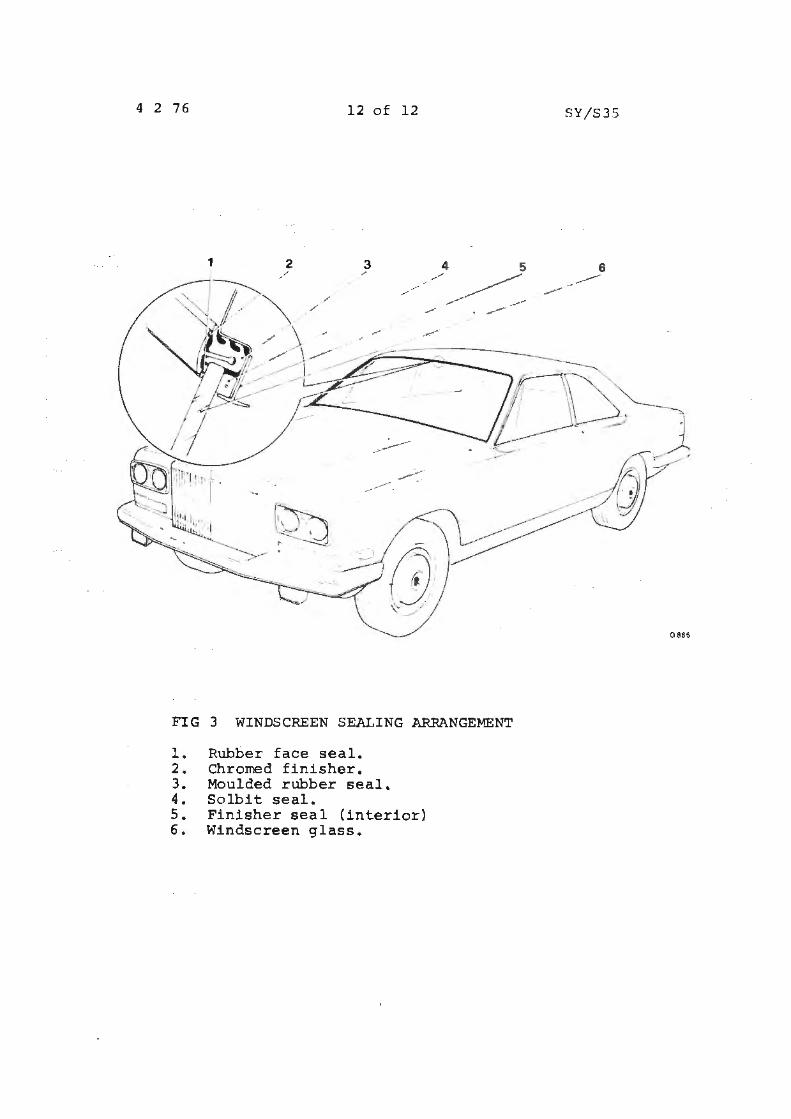
4 2 76 12 of 12
1 2 3 /
/
/
FIG 3 WINDSCREEN SEALING ARRANGEMENT
l. Rubber face seal. 2. Chromed finisher. 3. Moulded rubber seal. 4. Solbit seal. 5. Finisher seal (interior) 6. Windscreen glass.
SY/S35
6
-----
086$
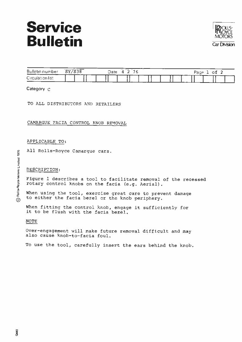
Service Bulletin
ID>a.LSJf\\OYCE MOTORS
Car Division
Bulletin number SY/S38 Date 4 2 76 Pa ge 1 of 2 Circulation list j ! ! I II I 11 11 II 11 I II I Category c
TO ALL DISTRIBUTORS AND RETAILERS
CAMARGUE FACIA CONTROL KNOB RE~OVAL
APPLICABLE TO:
All Rolls-Royce Camargue cars.
DESCRIPTION:
Figure 1 describes a tool to facilitate removal of the recessed rotary control knobs on the facia (e.g. Aerial).
When using the tool, exercise great care to prevent damage to either the facia bezel or the knob periphery.
When fitting the control knob, engage it sufficiently for it to be flush with the facia bezel.
NOTE
Over-engagement will make future removal difficult and may also cause knob-to-facia foul.
To use the tool, carefully insert the ears behind the knob.
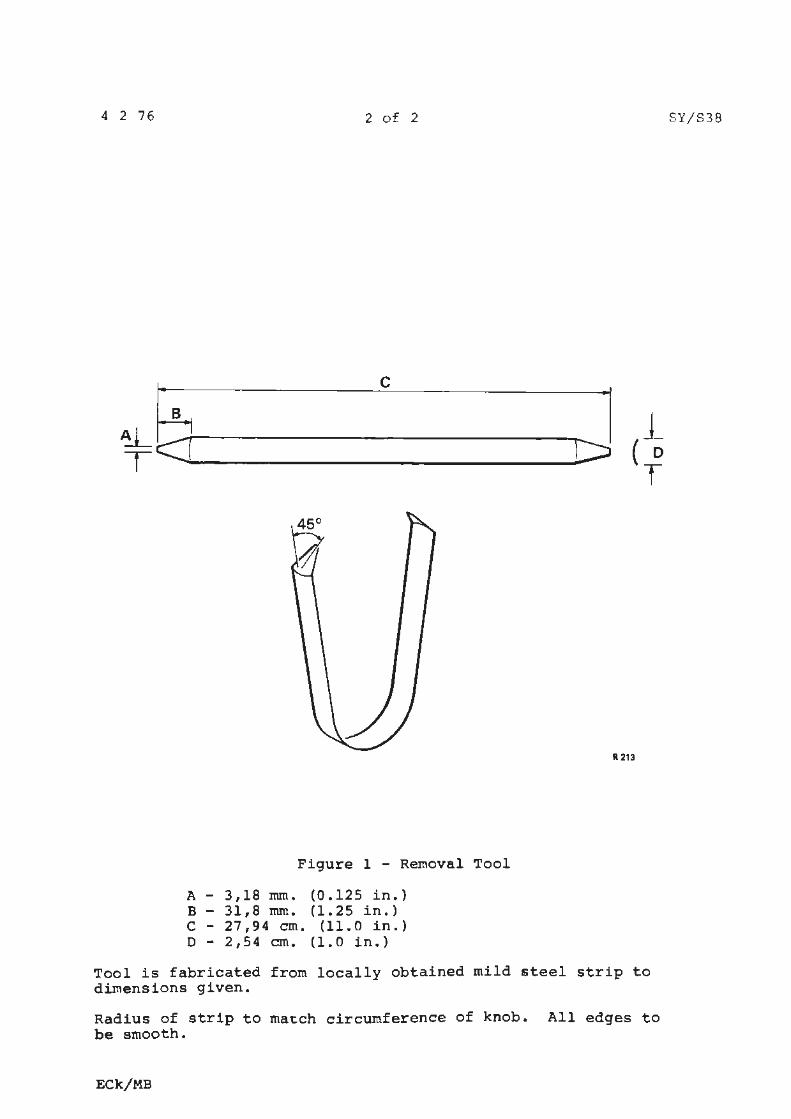
4 2 76 2 of 2
C
~~---------J
Figure 1 - Removal Tool
A - 3 , 18 mm • ( 0 • 12 5 in. } B - 31,8 nun. (1. 25 in.) C - 27,94 cm. (11.0 in.) D - 2,54 cm. (1.0 in.)
ll. ·213
Tool is fabricated from locally obtained mild steel strip to dimensions given.
Radius of strip to match circumference of knob. All edges to be smooth.
ECk/MB
SY/S38
Service Bulletin
Bulletin n·umber SY /S 39
Circulation list I r 11
Category c
Date
11 I
TO ALL DISTRIBUTORS AND RETAILERS
REPAIR PRIMER SUFFACER
APPLICABLE TO:
IR{~i MOTORS
(.arOMsJon
4 2 76
JI Page 1 of 1
II I II l 11 I I I
i All Rolls-Royce Carnargue, Corniche and Silver Shadow cars and J all Bentley Corniche and 'T' Series cars. e :J <I)
I l f i @
DESCRIPTION:
Inmont light grey acrylic repair primer surfacer (U34 AV016 Rolls-Royce code 9502921) has now been replaced by Inmont grey green acrylic repair primer surfacer (U34 GV004 Rolls-Royce code 9202922).
This change has been made to avoid confusion between the cellulose and acrylic repair primers which are currently both liqht grey in colour.
We stress that the change is in colour only and the new material can be used as a direct replacement in all applications.
Service Bulletin
. Si1S4I Bulletin n·umber - Date I6 2 76 Page
Circulation list I I I I 11 I 11 11 11 11
Category C
ALL DISTRIBUTORS AND RETAILERS
BODY PANELS
APPLICABLE TO:
All Silver Shadow, T Series, Corniche and Camargue motor cars.
i ! DESCRIPTION:
"' } In the event of exterior body panels having to be changed, 8 it should be noted that replacement panels may need localised >- hand trimming to ensure an exact fit. 1 ~ This trimming plus any other adjustments must be carried out ® to the panel being painted.
I
~&~ MOfORS
CarC>Msion
l of 1
11
Service Bulletin
Bulletin number SY/S 42
CircL:lation list
Category C
11 11
TO ALL DISTRIBUTORS ANP RETAILERS
FRONT AND REAR WINDSCREENS
APPLICABLE TO:
1 3 76o a te
11 I 11 11
All Rolls-Royce Camargue, Corniche and Silver Shadow cars and all Bentley Corniche and T Series cars.
~ ... ~ '1:1
~ESCRIPTION : c:: :J
Page
11 I
I I I li))QLLSlf'\oYCE
'. MOTORS I Car Division
TSO 41 71
1 of 2
11
~hould it be intended to change.a front or rear windscreen under ~ e terms of the Rolls-Royce Motors Warranty which covers body items Bf or a period of one year, authorisation must always be obtained from &Rolls-Royce Motors Ltd before removing the glass from the car. Ji
£.Having obtained authorisation the faulty glass can be removed and @)3crapped. Do not return the glass to Rolls-Roy·ce Motors Lt.d,· unless requested to do so . -
In order to expedite any resulting Warranty Claims would you please ensure that the Service Label and Warranty Cl~im Form, are correctly completed and include the glass date code. Failure to include the glass code will result in the Warranty Claim Form being returned.
It should be noted that the inclusion of the glass code applies t o front and rear windscreen only.
The year and month of glass manufacture are determined by a series of dots above and below the words 'Triplex Laminated' which are e t ched in the left hand lower corner of the glass.
The year of manufacture is determined by where the dot is situated beneath the word Laminated. As this word has only nine letters, for the tenth year, the dot is placed beneath an invisible tenth letter as shown in the example for 1970.
EXAMPLE 1969 = LAMINATED •
1970 = LAMINATED.
1974 = LAMINATED •
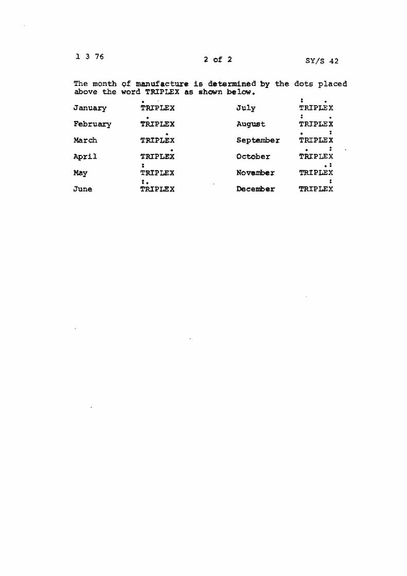
l 3 76 2 of 2 SY/S -42
The month Qf manufacture is d.eteminea by the dots placed above the word TRIPLEX as shown be lCM.
January
February
March
April
May
June
• TRIPLEX
• TRIPLEX
• TRIPLEX
• TRIPLEX : TRIPLEX • •• TRIPLEX
July
August
September
October
Noveni>er
December
: • TRIPLEX . . . TRIPLEX . • • TRIPLEX
• . .
TRIPLEX . .. TRIPLEX .
• TRIPLEX
Service Bulletin
Bulletin number S!/S43 Date
(i))QLLSff'\OYCE MOTORS
Car Division
TSD 4171 27 5 7& 1 of l
Page Circu/.ation list II II II II II II I II Category C
ALL DISTRIBUTORS AND RETAILERS
REPAIR PRIMER SURFACER
APPLICABLE TO:
All Rolls-Royce Ca.marque, Corniehe and Silver Shadow motor cars ~ and all Bentley Corniche and 1T' Series motor cars finished in ~ Full Thermoplastic Acrylic Paint. ~
"' 0 o DESCRIPTION: ;:,
J To avoid confusion between Cellulose and Acrylic Repair Primers l which are currently both 'Light Grey' in colour, the colour of £ the Acrylic repair primer has been changed to 'Grey - Green'. ® 'l'he chemical specification of the primer remains unchanged.
'GREY - GREEN' Acrylic Repair Primer Surfacer
OB 33665 U34GV004 9502022 - INMONT
REPIACES
'LIGHT GREY' Acrylic Repair Primer Surfacer
UB 33278 U34AVOl6 9502921 - INMONT
Hly/MB
Service Bulletin
Bulletin number SY7S'15 Date I7 6 7~ Page
11 11 Circulation list
Category C
ALL DISTRIBUTORS AND RETAILERS
MANUALLY OPERATED 'BULLS EYE' FLAP
~ APPLICABLE TO: ~
11 11 11 II
~ All Rolls-Royce Camargue motor cars after car serial number ! JRH 23608.
i ::ii
[ j INTRODUCTION: ~
£ There have been minor alterations to the Camargue facia from © the above car serial number.
DESCRIPTION:
I
The manual flap in the circular outlets (commonly known as the 'bulls eyes') is no longer fitted, and the airflow through these outlets is now controlled automatically.
Hly/MH
I
~ I lf\~oYCE I I MOTORS I Car Division
TSO 4171
or I
11
[i))QLLS· rr,\oYCE ."..'10TO~S
Service Bulletin Car Division
Bulletin number
Circulation li st
Category C
ALL DISTRIBUTORS AND RETAILERS
KANGOL EUROFLEX SErlT BELTS WITH PRESSURE RELIEF DEVICE (PRD)
APPLIC.;;.BLE TO:
All Ro lls -Royce and Bentley Corniche cars g iven in the following list, ~ i ch the excep~ion cf cars des~ined f or the State of Californ ia and :C:u..:-cpe ('C:r::. excepteo.j.
DRH 25 043 to DRE 26284 - Convertib le cars CRH 25044 to CRH 30021 - Two door saloons
INTRODUCTION:
A seat belt incorporat ing a pressure relief device ('window shade ' retractor type} has been fitted to a number of cars between the car serial numbers previously quoted.
The pressure relief device assists in reducing the chest/shoulder pressure which is a normal feature of inertia reel seat belts .
To obtain the benefits of the device, the wearer(s} should fasten and adjust the seat belt to the desired requirement of the individual as with conventional inertia reel seat belts, then withdraw the shoulder strap between 6,4mm and 13mm (0.25 i n . and 0.50 in.) and release. The PRD device will then maintain the selected pressure until a deliberate forward movement of the wearer exceeds approximately 2,5cm to 5,0cm (1.0 in. to 2.0 in.). At this point the seat belt will revert to the higher retraction load normally associated with conventional inertia reel belts.
Should the wearer(s) lean f orward an abnormal amount or, completely unwind the webbing off the reel, the belt may not retract. In this case the small release lever situated on the seat belt reel housing at the base of the B post should be operated. This allows the belt to retract.
~ Hly/MB
Service Bulletin
Bulletin nuri'ber SY/548 25
Date 1 ,a
Page Circulation 11st
C Category
11
ALL FRANCHISE HOLDERS
11 11
SILVER WRAITH II DOOR CAPPING FINISHERS
APPLICABLE TO:
All Rolls-Royce Silver Wraith II cars.
DESCRIPTION:
II II ·II I
This Service Bulletin details the procedures for the renewal/ fitting of the stainless door capping finishers.
PROCEDURE:
CAPPING FINISHER - TO REMOVE (ALL DOORS) . • "'
1. Drill out the rivet securing the capping finisher front edge to the door.
2. Pull the finisger away from the door until it assumes an angle of 45 to the door. Move the finisher rearwards so that it unclips itself from the door trailing edge. 00 not damage the rubber seal.
CAPPING FINISHER - TO FIT (FRONT DOOR)
1. Clean the door painted surface and the underside of the finisher.
If a new capping finisher is to be fitted it will be supplied in spares form in two pieces - the finisher and the forward edge retainer. The finisher should be measured to the individual door, cut to size and then the finisher and forward edge retainer must be Argon gas welded, dressed and polished.
ID)QLLSrf'\\OYCE MOTORS
Car Division
TSO 4171
1 or
11
3
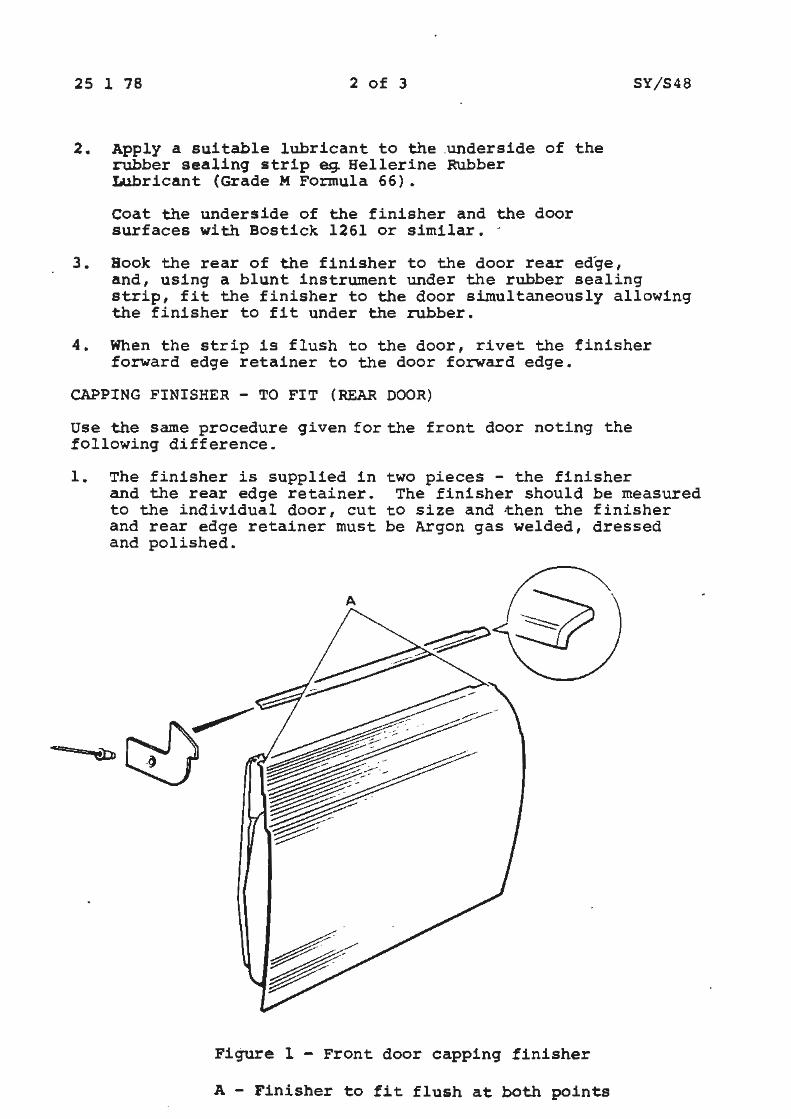
cn,g
25 l 78 2 of 3
2. Apply a suitable lubricant to the .underside of the rubber sealing strip eg. Hellerine Rubber Lubricant (Grade M Formula 66).
coat the underside of the finisher and the door surfaces with Bostick 1261 or similar. -
3. Book the rear of the finisher to the door rear edge,
SY/S48
and, using a blunt instrument under the rubber sealing strip, fit the finisher to the door simultaneously allowing the finisher to fit under the rubber.
4. When the strip is flush to the door, rivet the finisher forward edge retainer to the door forward edge.
CAPPING FINISHER - TO FIT (REAR DOOR)
Use the same procedure given for the front door noting the following difference.
1. The finisher is supplied in and the rear edge retainer. to the individual door, cut and rear edge retainer must and polished.
two pieces - the finisher The finisher should be measured
to size and then the finisher be Argon gas welded, dressed
Figure l - Front door capping finisher
A - Finisher to fit flush at both points
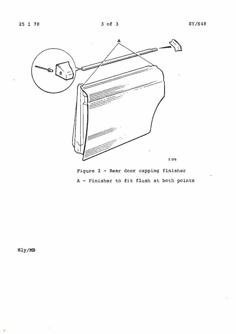
25 1 78 3 of 3 SY/S48
Figure 2 - Rear door capping finisher
A - Finisher to fit flush at both points
Hly/MB
I
I Service Bulletins
Chapter T ~ Transmission
I Service Bulletins
Chapter U 149" EmissiQn Control Systems

i i J
j
I i ®
Service Bulletins
Chapter PVI Phantom VI
Service Bulletin
Bulletin number l?VI/Rl
Circulation 11st I I Category C
11 11
ALL DISTRIBUTORS AND RETAILERS
Date 7
II 11
APPLICABLE TO ROLLS-ROYCE PHANTOM V A..~D VI CARS
TYRE SIDEWALL MARKING
INTRODUCTION
10 77 Pa ur-,
11 11
The sidewall marking on tyres fitted to Phantom V and VI cars, is to be changed in anticipation of forthcoming legislation.
DESCRIPTION
The previous marking 8.90 H-15 Dunlop Fort C will be changed to 8.90 S-15 Dunlop Fort. The tyre size and construction will remain unchanged. It is inevitable that as tyres are replaced on motor cars, some cars will have tyres with the two different markings. The perfonnance and handling of the cars will not be affected in any way.
Hly
ID)OLLSf("\\OYCE MOTORS
-Car Division
TSD 4171
1 of l
11