rolling stock planning at dsb s-tog - processes, cost ... · rolling stock planning at dsb s-tog...
TRANSCRIPT
General rights Copyright and moral rights for the publications made accessible in the public portal are retained by the authors and/or other copyright owners and it is a condition of accessing publications that users recognise and abide by the legal requirements associated with these rights.
Users may download and print one copy of any publication from the public portal for the purpose of private study or research.
You may not further distribute the material or use it for any profit-making activity or commercial gain
You may freely distribute the URL identifying the publication in the public portal If you believe that this document breaches copyright please contact us providing details, and we will remove access to the work immediately and investigate your claim.
Downloaded from orbit.dtu.dk on: Mar 29, 2020
Rolling Stock Planning at DSB S-tog - Processes, Cost Structures and RequirementsTechnical Report
Thorlacius, Per
Publication date:2015
Document VersionPublisher's PDF, also known as Version of record
Link back to DTU Orbit
Citation (APA):Thorlacius, P. (2015). Rolling Stock Planning at DSB S-tog - Processes, Cost Structures and Requirements:Technical Report. DTU Management Engineering.
Rolling Stock Planning at DSB S-togProcesses, Cost Structures and Requirements
Technical Report
Per Thorlacius, M. Sc. ∗
November 3, 2015
Abstract
A central issue for operators of suburban passenger train transport systems isproviding sufficient number of seats for the passengers while at the same timeminimising operating costs. The process of providing this is called rolling stockplanning. This technical report documents the terminology, the processes, the coststructures and the requirements for rolling stock planning at DSB S-tog, the subur-ban passenger train operator of the City of Copenhagen. The focus of the technicalreport is directed at practical train operator oriented issues. The technical report isthought to serve as a basis for investigating better methods to perform the rollingstock planning (to be the topic of later papers). This technical report is produced asa part of the current industrial Ph. D. project to improve the rolling stock planningprocess of DSB S-tog.
∗Danish State Railways, DSB, Development and Optimisation Dept., Telegade 2, DK-2630 Tåstrup,Denmark
1
Contents
1 Introduction 31.1 The Purpose of Rolling Stock Planning . . . . . . . . . . . . . . . . . . . . 31.2 How This technical report is Organised . . . . . . . . . . . . . . . . . . . 3
2 Terminology 3
3 The Rolling Stock Planning Process 63.1 Aspects of Circulation Planning . . . . . . . . . . . . . . . . . . . . . . . . 6
3.1.1 Composition Planning . . . . . . . . . . . . . . . . . . . . . . . . . 83.1.2 Rotation Planning . . . . . . . . . . . . . . . . . . . . . . . . . . . 83.1.3 Depot Planning . . . . . . . . . . . . . . . . . . . . . . . . . . . . . 9
3.2 Aspects of Train Unit Dispatching . . . . . . . . . . . . . . . . . . . . . . 93.2.1 Train Unit Dispatching in a Situation without Disruptions . . . . 93.2.2 Train Unit Dispatching in a Situation with Disruptions . . . . . . 10
4 Cost Structures for Rolling Stock Operation 114.1 Background and Terminology . . . . . . . . . . . . . . . . . . . . . . . . . 114.2 Operating Cost Types and Structure . . . . . . . . . . . . . . . . . . . . . 124.3 Costs not Considered . . . . . . . . . . . . . . . . . . . . . . . . . . . . . . 13
5 Practical Requirements for Rolling Stock Planning 135.1 Requirements Independent of the Individual, Physical Train Unit . . . . 13
5.1.1 Infrastructure . . . . . . . . . . . . . . . . . . . . . . . . . . . . . . 135.1.2 Timetable . . . . . . . . . . . . . . . . . . . . . . . . . . . . . . . . 175.1.3 Rolling Stock . . . . . . . . . . . . . . . . . . . . . . . . . . . . . . 195.1.4 Passenger Demand . . . . . . . . . . . . . . . . . . . . . . . . . . . 215.1.5 Personnel on Duty . . . . . . . . . . . . . . . . . . . . . . . . . . . 24
5.2 Requirements Dependent of the Individual, Physical Train Unit . . . . . 245.2.1 Scheduled Maintenance . . . . . . . . . . . . . . . . . . . . . . . . 245.2.2 Unscheduled Maintenance . . . . . . . . . . . . . . . . . . . . . . 275.2.3 Friction Sand . . . . . . . . . . . . . . . . . . . . . . . . . . . . . . 275.2.4 Exterior Cleaning . . . . . . . . . . . . . . . . . . . . . . . . . . . . 285.2.5 Exterior Graffiti Removal . . . . . . . . . . . . . . . . . . . . . . . 285.2.6 Interior Cleaning . . . . . . . . . . . . . . . . . . . . . . . . . . . . 285.2.7 Winter Preparedness . . . . . . . . . . . . . . . . . . . . . . . . . . 285.2.8 Exposure of Commercials . . . . . . . . . . . . . . . . . . . . . . . 295.2.9 Surveillance Video Requests . . . . . . . . . . . . . . . . . . . . . 295.2.10 Surface Foil Application . . . . . . . . . . . . . . . . . . . . . . . . 295.2.11 Passenger Counting Equipment . . . . . . . . . . . . . . . . . . . 295.2.12 Train Control System Equipment . . . . . . . . . . . . . . . . . . . 29
6 Further Research 306.1 Integrating Circulation Planning and Train Unit Dispatching . . . . . . . 306.2 Evaluating Alternative Maintenance Scheduling Strategies . . . . . . . . 31
Acknowledgements 32
References 32
2

1 Introduction
This technical report deals with the planning of rolling stock for DSB S-tog, the subur-ban passenger train operator of the City of Copenhagen.
1.1 The Purpose of Rolling Stock Planning
The overall purpose of rolling stock planning is to supply train seats in time and spaceto fulfil the passenger demand while minimising operating costs. This is conductedby assigning rolling stock train units to train services. As such, a train service is servedby one or more train units and runs between an origin station and a terminal stationcalling at zero or more intermediate stations on the way at points in time as stipulatedin the timetable. When passenger demand is high, train units providing a high seatingcapacity shoudl be assigned to the individual train service. When demand is low, aminimum of train units may be assigned to the individual train service.
1.2 How This technical report is Organised
This technical report sets out in chapter 2 by defining the terminology used. Chapter2 thus provides the answer to the question: What do we call the different aspects of rollingstock planning?
Next, chapter 3 describes the rolling stock planning process of DSB S-tog and itssubprocesses. Chapter 3 is thus the answer to the question: How is rolling stock planningperformed at DSB S-tog?
Chapter 4 describes the cost structures related to operating the rolling stock, an-swering the question: What factors of the operation induce what cost?
A rolling stock plan must adhere to a number of practical, railway oriented re-quirements. These requirements are described in detail in chapter 5. An overview ofthe requirements may be found in table 3 on page 14. This table also shows whichrequirements are handled in which of the subprocesses of the rolling stock planningprocess. As such, chapter 5 answers the question: What requirements do we need to takeinto account when performing rolling stock planning?
Finally, chapter 6 presents an outlook to future research.
2 Terminology
This chapter contains brief definitions of the most important terms used in this techni-cal report. References to more detailled descriptions of the terms and their implicationsare given where applicable. Terms in italics refer to other definitions in the list.
• A station is a point in space where a train service may stop to allow passengers toget on or off.
• A train service is the concept of transport using trains on the main railway tracks,provided as a service to passengers and/or to perform positioning of train units.A train service runs between an origin station and a terminal station stopping at orskipping zero or more intermediate stations on the way at points in time as sched-uled in the timetable.
3

• A revenue train service is a train service provided for the transport of passengersfor revenue.
• A non-revenue train service is a train service that is running without passengersin order to position the train units.
• Skipping is when a train service passes a station without stopping. Skipping occursas scheduled in the timetable for express train services, in disruption managementfor delayed train services to catch up, and for non-revenue train services that carryno passengers.
• Positioning is the process of moving train units in one or more train services inorder to meet later demand for seats or technical maintenance at other points inspace.
• Revenue positioning is the positioning of train units by providing more train unitsin a revenue train service than is in demand by passengers, thus offering excessseating capacity.
• Non-revenue positioning is positioning in non-revenue train services with no pas-sengers. This is also known as dead-heading.
• A timetable is a complete list of revenue and non-revenue train services for a givenperiod of time. Only the revenue train services are published to the general public.For details, see section 5.1.2.
• An origin station is a station from which a train service starts.• A terminal station is a station at which a train service ends.• An intermediate station is a station during the run of a train service at which the
train service may either be stopping or skipping.• The train drivers constitute the staff group performing train services. Train drivers
also perform the part of train shunting that is to and from side tracks.• A depot is the entire infrastructure at a station used for train shunting and parking
of train units at depot tracks. All depots have facilities for cleaning and some havefacilities for maintenance.
• A maintenance depot is a depot with maintenance facilities.• A depot station is a station which has a depot.• A depot track is a track at a depot where train units may be parked when not
running as a train service.• A split depot is a depot at a station at which some of the depot tracks are only
reachable from some of the platform tracks and vice verse. Hillerød station has assplit depot, as seen on Figure 2 on page 15.
• A terminal depot is a depot located at a terminal station.• A same direction depot is a terminal depot located so that train services arriving to
its depot station may reach the same direction depot by continuing through the depotstation in the same direction of movement. Train shuntings arriving from a samedirection depot may also continue through its depot station in the same direction ofmovement to become train services departing from that depot station. Høje Tåstrupstation has a same direction depot, as seen on Figure 2 on page 15. Note that thetracks below the station on Figure 2 belong to the maintenance workshop.
• An opposite direction depot is a terminal depot located so that train services ar-riving to its depot station may only reach the opposite direction depot by changingdirection of movement at the depot station. Train shuntings arriving from an op-posite direction depot must also change their direction of movement at the depotstation to become train services departing from that depot station. Køge station hasa opposite direction depot, as seen on Figure 2 on page 15.
4

• A intermediate depot is a depot located at an intermediate station. Train units en-tering an intermediate depot may continue in the same direction or must changedirection depending on the direction in which they are arriving at the intermedi-ate depot. København H station has an intermediate depot, as seen on Figure 2 onpage 15.
• A platform track is a track at a station where a train service may stop and allowpassengers to get on or off. A platform track may also be temporary used for theparking of train units.
• A side track is a track that can only be used for parking in the day time. There isno internal train shunting between side tracks.
• A side track station is a station which has side tracks. As opposed to a depot station,there are no facilities for cleaning or maintenance.
• A train shunting is the operation of coupling and decoupling train units at depotstations or side track stations as well moving the train units to and from platformtracks, depot tracks and side tracks.
• The depot drivers constitue the staff group performing those train shuntings thatare in and out of a depot.
• A train line is an aggregation of similar train services according to the time of daythey are running, the stations they are visiting etc.
• A train service sequence is a consecutive sequence of train services, on the same(or related) train line, for which it is a natural choice that the train units be reusedfrom one train service to the next. The train service sequences of a time table may bedetermined from the layout of tracks, the minimum and maximum turnaroundtimes between two consecutive train services at the origin and terminal stations andby the braiding policy. The concept of train service sequences is used to ease themanual rolling stock planning process. The first and last train service in a trainservice sequence may not require a depot driver to shunt the corresponting trainunits out from or into the depot, since the train driver for the train service has timeto perform this operation as his first or last task in his duty.
• Braiding is when there are train services from different train lines in the sametrain service sequence. Braiding may yield better utilisation of the train units atthe cost of a lower robustness since disruptions may then propagate betweentrain lines. Under certain conditions braiding may produce train service sequencesthat represent one direction of one train line and the opposite of another, a highlyundesireable feature from a robustness point of view. Forced braiding may alsobe used to raise the robustness by forcing higher turnaround times.
• Depot internal shunting is the the process of train shunting between depot tracksat the same depot station. A platform track may be involved in the process, but depotinternal shunting starts at one depot track and finishes at another.
• A train service segment is the individual part a train service performs betweendepot stations or side track stations for that particular train service. Since there areno depot stations or side track stations en route on a train service segment, the traincomposition of a train service will remain constant.
• A train shunting segment is the individual part of a train shunting between plat-form tracks, depot tracks or side tracks for a particular train shunting. Analogous totrain service segments, the composition remains constant in a train shunting segment.
• A train unit is the actual, physical, individual, inseparable railway vehicle. Fordetails, see section 5.1.3.
• The train unit type is the technical type of a train unit. For details see section
5

5.1.3.• A train unit trajectory is the path a train unit moves through consecutive train
service segments and train shunting segments to fulfil its tasks over a period of time.• A train composition is the ordered sequence of coupled, individual train units
assigned to an individual train service segment or train shunting segment.• A train composition type is the anonymous, non-ordered composition of a train
service segment or train shunting segment specifying only train unit types. For de-tails, see section 5.1.3.
• A total composition exchange is when all train units in two consecutive trainservice segments in a train service sequence are exchanged.
• A partial composition exchange is when only some of the train units in two con-secutive train service segments in a train service sequence are exchanged.
• A rolling stock plan is the assignment of all available train units to train unit tra-jectories that combined satisfy the operational requirements. The set of train unittrajectories implicitly determines the train composition of each train service segmentand train shunting segment. This implies how much seating capacity is offered inthe individual train service segments and when and where train units are parked atthe depots.
3 The Rolling Stock Planning Process
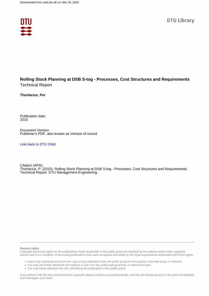
At DSB S-tog, the process of rolling stock planning is currently divided into two sub-processes. The first subprocess is the long term circulation planning and the secondsubprocess is the short term train unit dispatching. Aspects of these subprocesses aredescribed in this chapter. Figure 1 shows an overview of the current rolling stock plan-ning process at DSB S-tog and its subprocesses. Table 1 shows an overview of thedifferent characteristics for the specific subprocesses circulation planning and train unitdispatching with disruptions.
(Note that at DSB S-tog, the routing of train services on the main line and throughstations is not considered a part of the rolling stock planning process, but rather a partof the timetabling process. In the rolling stock planning process one can thus assume,that there is sufficient capacity on the tracks and in the stations to operate the giventimetable.)
3.1 Aspects of Circulation Planning
The long term part of the current rolling stock planning process at DSB S-tog is calledcirculation planning. According to the current protocol, the circulation planning pro-cess must be started at least three months before and completed at least three weeksbefore the plan is to be commenced (that is, put into motion).
For this reason, at the time the circulation planning is conducted, it is not knownwhich physical train units are available when the plan is to be commenced. Sometrain units may be in unscheduled maintenance, see section 5.2.2 and it is not knownwhere the physical train units are situated at the time the plan is to be commenced,since changes to the previous plan may have occurred. For this reason the circulationplanning is performed for virtual train units, that is, anonymous train units which haveno individual characteristics apart from those involved in the plan.
6
Rolling Stock Planning
Circulation Planning
CompositionPlanning
RotationPlanning
DepotPlanning
Train Unit Dispatching
WithoutDisruptions
WithDisruptions
Figure 1: The rolling stock planning process at DSB S-tog and its subprocesses.
Table 1: Overview of the different characteristics for the processes circulation planningand train unit dispatching with disruptions.
Subject Characteristics of the process Characteristics of the processcirculation planning train unit dispatching w/disruptions
Planning scope The everyday operation For occasionally occurring disrup-tions
Planning horizon Long term Short term (real time)
Time for processing Long Very short
Goal Stable operation To recover to stable operation
Instruments used A limited number (to ensure sim-plicity and robustness)
Every possible one (to ensure op-eration is resumed quickly)
Requirements Strict (planned violation not toler-ated)
Not so strict (one-time violationstolerated)
Cost of plan Important (cost is incurred everyday)
Not so important (cost is incurredonly once)
7
The term circulation planning is thus analogous to the term crew pairing in the air-line industry, except in this case the pairing is performed for virtual train units, notvirtual crew members [5].
At DSB S-tog the circulation planning is currently performed as three separate sub-processes that are executed one after the other as composition planning, rotation planningand depot planning. These three subprocesses are described in the following sections,and may also be seen on figure 1.
3.1.1 Composition Planning
The subprocess of deciding how many virtual train units to assign to a train service inorder to meet passenger demand is called composition planning. The main requirementsto this process are the infrastructure, the rolling stock, the timetable and the passengerdemand (see sections 5.1.1 to 5.1.4). The output of the process is a composition plandefining the amount of virtual train units to assign to each train service, making surethat the overall depot track length of each of the depots is not exceeded by parked trainunits at any time, that each virtual train unit can only be part of one train service at atime, and that train unit balance is kept.
3.1.2 Rotation Planning
The next subprocess is called rotation planning and deals with deciding which virtualtrain unit is to move from a position in a train composition serving one train servicesegment to a position in a next train composition serving the next train service segment(possibly with a stop-over at a depot). This subprocess also takes into account whenand where the virtual train units should undergo scheduled maintenance, which, apartfrom the composition plan, is the main requirement for this subprocess. The scheduledmaintenance requirements are described in section 5.2.1 on page 24.
Typically, when there is not much change in passenger demand, a train unit inservice on a particular line (see explanation on figure 3, page 17) stays on that linewhen changing direction at the terminal station. Thus a train unit used in a train on aline in one direction typically rotates to become part of a train service in the oppositedirection on the same line when it reaches the terminal station.
As mentioned in chapter 2, a series of train services for which it is a natural choicethat the rolling stock train units be rotating from one train service to the next is calleda train sequence. Normally, train sequences are for the same line. Under certain condi-tions however, it may be more desirable to intertwine two lines to use the same rollingstock train units so that the train units change the line at one common terminal station.Such braiding train sequences may provide a better utilisation of the rolling stock at thecost of the robustness of the plan, that is, the ability of the plan to contain outside influ-ences with few negative consequences. The robustness of the plan is reduced since adelay on one line will propagate to the other line with which the delayed line sharesits rolling stock train units. Furthermore, the robustness is reduced because it may bemuch harder to recover manually from a disruption since the movement pattern of theindividual train units is more complicated.
8

3.1.3 Depot Planning
The subprocess of deciding how a virtual train unit is to be parked in a depot (whennot needed to perform train services) and how it is to be retrieved again (when it isneeded once more) is called depot planning. Apart from the rotation plan produced inthe previous step, the main requirements for this subprocess are the infrastructure andthe personnel on duty, see sections 5.1.1 and 5.1.5.
Some train operators do not consider depot planning a subprocess of circulationplanning, but rather a separate process in itself [1]. This is presumed to be for thereason that those operators have sufficient capacity in the depots to perform the de-pot planning process completely independent of the rest of the rolling stock planningprocesses. As mentioned, this is not the case for DSB S-tog.
In literature, the term shunting is used for the process of coupling and decoupling oftrain units and parking them in the depot [3]. At DSB S-tog, the more general term depotplanning is used including other processes like cleaning as well, not only shunting.
At DSB S-tog, the process of assigning depot drivers to the individual shuntingtasks is also a part of the depot planning process. This subprocess is called depot driverscheduling.
3.2 Aspects of Train Unit Dispatching
At DSB S-tog, the process of commencing a circulation plan (that is, putting the planinto motion) is called train unit dispatching. The time horizon for this process rangesfrom short (two days) to real-time.
The overall purpose of the process is to assign actual, physical train units to thevirtual train units in the circulation plan. As such, train unit dispatching is analogousto the term crew rostering in the airline industry, except in this case the rostering isperformed for train units, not crew [5].
The train unit dispatching process has two subprocesses each of which are per-formed under different conditions. The process of dispatching train units is as suchdifferent depending on whether disruptions are occurring or not, and different require-ments must be taken into account in the two subprocesses. This is shown in table 3 onpage 14 and the subprocesses themselves are explained in the following two sections.
3.2.1 Train Unit Dispatching in a Situation without Disruptions
When no disruptions occur, the object of the train unit dispatching process is to assigna physical train unit to each virtual train unit in the circulation plan. While doing so,it must be taken into account that the virtual train unit is planned to go into mainte-nance before the maintenance service distance limit of the physical train unit has beenreached. Furthermore, all of the requirements which were not taken into considerationin the circulation planning process need to be considered. This is shown in table 3 onpage 14.
The general idea (and purpose) is that the requirements already handled in the cir-culation planning process need not be considered in the train unit dispatching processwhen no disruptions are occurring.
9
3.2.2 Train Unit Dispatching in a Situation with Disruptions
In reality disruptions may occur at any time influencing how the plan (or parts ofit) may be realised. A robust circulation plan is able to accommodate these outsideinfluences with few changes to the original plan (timetable including) and a minimumof negative consequences for the passengers and the train operator.
At DSB S-tog, when a disruption occurs, the train controller of the infrastructureowner (BaneDanmark) is in charge of the overall recovery process, with the train unitdispatchers of DSB S-tog as co-operating partners.
In the case of disruptions, the train controller and train unit dispatchers may decideto disregard some of the of the requirements that needed consideration in the situationwithout disruptions. This is as to be able to handle a disruption before it gets outof hand. In the event of a disruption, it is of the utmost importance that sufficientaction is taken sufficiently quickly so as to contain the disruption and to prevent itfrom propagating into the entire network. Furthermore the action taken needs to be soas to be able to return to normal service as quickly and with as few changes to plan aspossible.
The instruments the train controller may use to conduct the recovery process mayinclude:
1. Cancelling individual train services, partially or completely, and cancelling entirelines;
2. Making individual train services skip planned stops at stations to make up forlost time;
3. Delaying train services.
The characteristics of the disruption and the instruments applied to remedy it pro-vide the conditions the train unit dispatchers will have to compensate for, since phys-ical train units may not be where the circulation plan states the corresponding virtualtrain units should be.
In the event of a disruption directly caused by a sudden train unit breakdown (re-quiring that the train unit must undergo unscheduled maintenance), the train con-troller and train unit dispatchers may choose solution strategies depending on thecharacteristics of the breakdown of the train unit(s) in the train. These characteristicsmay include:
1. Can the train composition move by itself?2. Can the train composition accelerate normally?3. Can the train composition travel at normal speed?4. Is the train composition or train unit allowed to carry passengers?
Solution strategies (multiple of which may be chosen) may include:
1. Off-load passengers at nearest station;2. Get the train composition or train unit out of the way in order not to obstruct
the movement of other train services. In extreme cases this may involve gettinganother train unit or locomotive to provide traction;
3. Get the the train composition or train unit to a side track or depot where it mayeither wait or be repaired by the mobile repair crew;
4. Get the train composition or train unit into one of the two maintenance work-shops;
10

5. Assign the physical train unit to run as a virtual train unit on the line that passesthe main maintenance workshop so as to let the workshop pick out the train unitfor maintenance when maintenance may be conducted;
6. Pick another train unit from the reserves to replace the one that has been takenout of service. Reserves are at Hundige, København H and Høje Tåstrup stations.
In the recovery phase after a disruption, one goal of the train unit dispatchers is toreach the depot balance of the original circulation plan. By doing so, the dispatchersmay ensure that the actual operations may return to being very close to or according tothe original circulation plan since the number of rolling stock train units in the depotswill be correct.
When reinstating train services on cancelled lines, certain rules must be adhered to.For example, if reinstating a cancelled train service, all subsequent train services on thegiven line must also be reinstated.
In the event of a disruption, the train unit dispatchers have at their disposal instru-ments that are not available to the planners in the planning phase. These instrumentsinclude the cancelling of train services, disregarding business rules regarding trainunit order in the train composition, disregarding rules about number of train units in atrain composition, disregarding rules as to how trains units may be coupled, and oth-ers. These dirty tricks are allowed in the recovery phase to prevent worse things fromhappening.
After a disruption, the physical train units may not be parked according to thecirculation plan at all. Which physical train units may run as which virtual train units(as defined in the circulation plan) is then highly dependent on how the physical trainunits are actually parked in the depot.
As may be concluded from the previous paragraphs, in the event of disruptions, thework of the train unit dispatchers always deals with compensating for the unexpectedevents that may occur. If a train unit breaks down, a compensation train unit must beprovided from the reserves. If train services are cancelled in the event of a disruptionand the depot balance of a depot is not according to plan, train units must be positionedto compensate for this.
4 Cost Structures for Rolling Stock Operation
4.1 Background and Terminology
The primary objective of moving train units around on the tracks of a railway is ofcourse to provide seats for the transportation of passengers. As such, most of the trainunit movements depend upon the given timetable. In order to be able to accommodatepassenger demand at all times, train units must often be moved from one location toanother before the actual demand occurs. This type of movement is called positioningand may be conducted as an individual train service without passengers as non-revenuepositioning or as revenue positioning by running passenger carrying train services withmore train units than the immediate demand for that particular train service. In thelatter case, the train unit being positioned is used as a functional part of the train com-position.
11

Table 2: Overview of the different different types of operating costs for a suburbantrain transport company in this case DSB S-tog. Primary acceleration energy is the energyneeded to accelerate the train composition to cruising speed upon departure from itsorigin station. Analogously, subsequent acceleration energy is the acceleration energyneeded at subsequent stations. Speed sustainment energy is the energy needed to sustaincruising speed. The costs for energy and maintenance for half-length type of train unitsare a bit more than half of that of the full-length type of train units.
Type Proportional Incurred Incurred byof cost to by revenue non-revenue
positioning positioning
Primary acceleration energy # of train units of type Yes Yes
Subseq. acceleration energy # of train units of type at station Yes No
Speed sustainment energy # of train units of type service dist. Yes Yes
Maintenance # of train units of type service dist. Yes Yes
Infrastructure Revenue train service distance No No
Train driver duties Engine drivers hired No Possible
Depot driver duties Depot drivers hired Possible Possible
4.2 Operating Cost Types and Structure
As may be seen from table 2, seven different types of operating costs are relevant forDSB S-tog as a suburban passenger train operator. The different types of costs areproportional to different factors of the operation, and are, as such, incurred by revenueor non-revenue positioning as stated in the table and described in the following.
All train units in a train composition need primary acceleration energy to reachcruising speed upon departure from the origin station, regardless of whether the trainunits perform revenue or non-revenue positioning. However, since a non-revenue po-sitioning train service is not stopping at intermediate stations, no subsequent accelera-tion energy is needed. The energy needed to sustain cruising speed is proportional tothe distance each train unit moves, regardless of positioning type.
The maintenance costs are also proportional to the distance each train unit moves,and as such, regardless of positioning type.
The fee for using the railway infrastructure is only levied for revenue train services.As such, there is no extra infrastructure cost for non-revenue positioning. There is alsono extra infrastructure cost for revenue positioning, because the fee has already beenpaid for the train service that is involved in the revenue positioning, since this trainservice runs with passengers according to the given timetable. In this sense, one couldsay that the infrastructure costs are solely determined by the given timetable.
Similarly, the train driver duty costs are strongly dependent on the given timetablesince each train service must have a train driver. If a decision is made to perform a rev-enue positioning, this will not induce additional driver duties, since the train servicealready has a train driver. However, deciding to perform a non-revenue positioningmay (under certain conditions) require that another train driver be hired to drive thetrain composition to be positioned (if the number of train drivers hired and on duty isnot sufficient to perform this task).
12

The costs related to the depot drivers are proportional to the number of depotdrivers hired. Under certain conditions there may not be enough depot drivers hiredand on duty to perform the train movements that may be required to perform a posi-tioning, regardless of positioning type. In this case, additional depot drivers must behired, thus inducing a higher cost.
Note that the energy and maintenance costs for half-length type of train units are abit higher than half of that of the full-length type of train units.
4.3 Costs not Considered
Of course a train unit that undergoes revenue positioning is being worn more andneeds more interior cleaning than a train unit that undergoes non-revenue positioning,since it is carrying passengers. However, since there will also be fewer passengers inthe other train units of the train composition, this effect is considered negligible.
The energy usage for train movements in the depot is also considered negligible.
5 Practical Requirements for Rolling Stock Planning
This chapter describes the practical, train operator oriented requirements for rollingstock planning. For an overview of the requirements, please refer to table 3.
Each requirement is either dependent or independent of the individual physicaltrain unit. This distinction may prove important in the later modelling process sincethe number of possible combinations may be highly reduced when one is not requiredto take combinations of all the individual train units into account but only the trainunit type.
Table 3 also shows in which subprocess in the current planning process the require-ments are handled.
On a general note, it is general practice at DSB S-tog, that exemptions from the re-quirements described here may be made. Such exemptions are made in order to make amanually produced rolling stock plan work in the “real world”, i. e. with the resourcesgiven. This of course makes it harder to model the rolling stock planning process asit is currently performed, since it is not generally known which requirements may beexempted by which conditions. It also makes it harder to compare plans created man-ually with plans created automatically.
5.1 Requirements Independent of the Individual, Physical Train Unit
This section describes the requirements to the rolling stock planning process that areindependent to (that is, not related to) the individual physical train unit. For example,the requirements related to the infrastructure are independent of the individual physi-cal train unit because it does not matter which individual physical train unit of a giventype occupies a track. Any other individual physical train unit of that type may just aswell occupy that track.
5.1.1 Infrastructure
One of the main requirements for rolling stock planning is of course (as with almostall other aspects of railway operation planning) given by the railway infrastructure.
13

Table 3: Overview of the requirements for rolling stock planning at DSB S-tog. Inthe table the column Indep. means independent of the actual, physical train unit, thecolumn Circ. means handled in the rolling stock circulation planning process, No Disr.means handled in the train unit dispatching process when there are no disruptions,and Disr. means handled in the train unit dispatching process when disruptions haveoccurred and a recovery is in progress. Statements in parenthesis indicate likely futuredecisions.
Section Requirement Indep. Circ. No Disr. Disr.
5.1.1 Infrastructure Yes Yes No Yes
5.1.2 Timetable Yes Yes No Yes
5.1.3 Rolling Stock Yes Yes No Yes
5.1.4 Passenger Demand Yes Yes No Yes
5.1.5 Personnel on Duty Yes Yes No Yes
5.2.1 Scheduled Maintenance No Yes Yes Yes
5.2.2 Unscheduled Maintenance No No Yes Yes
5.2.3 Friction Sand No No Yes Yes
5.2.4 Exterior Cleaning No No Yes No
5.2.5 Exterior Graffiti Removal No No Yes No
5.2.6 Interior Cleaning No No Yes No
5.2.7 Winter Preparedness No No Yes No
5.2.8 Exposure of Commercials No No Yes No
5.2.9 Surveillance Video Requests No No Yes No
5.2.10 Surface Foil Application No No Yes No
5.2.11 Passenger Counting Equipment No No Yes No
5.2.12 Train Control System Equipment (No) (Yes) (No) Yes
14
OrdrupCharlottenlund
Østerport
NørreportSvanemøllen
Vesterport
RyparkenKøbenhavn H
EmdrupBernstorffsvej
DyssegårdVangede
GentofteKildebakke
BispebjergJæ
gersborg
Buddinge
LyngbyStengården
ØlstykkeSorgenfri
Bagsværd
VirumSkovbrynet
EgedalStenløse
HareskovVeksø
Værløse
KildedalMåløv
EnghaveSjæ
lør
ÅmarkenHøvelte
Ballerup
FrihedenMalmparken
AvedøreSkovlunde
Brøndby Strand
Vallensbæk
IshøjRødovre
Brøndbyøster
Glostrup
Greve
Ølsemagle
Klampenborg
HillerødBirkerød HolteHøje Tåstrup
Allerød
HellerupFarum
LersøenFrederikssundHerlevTåstrup
Albertslund
Husum Fuglebakken NørrebroGrøndalIslevJyllingevej NordhavnSkelbæk
DybbølsbroVanløseFlintholm
K.B. HallenPeter Bangsvej
Køge LanggadeÅlholmDanshøj Valby
Hvidovre
Ølby Vigerslev AlléBavnehøj
Ny EllebjergKøge Nord Sydhavn
Jersie
Solrød HundigeStrand
Karlslunde
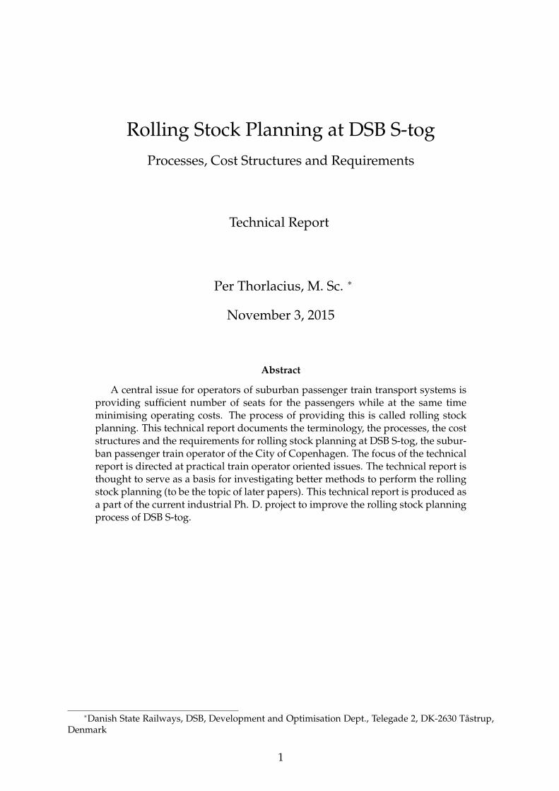
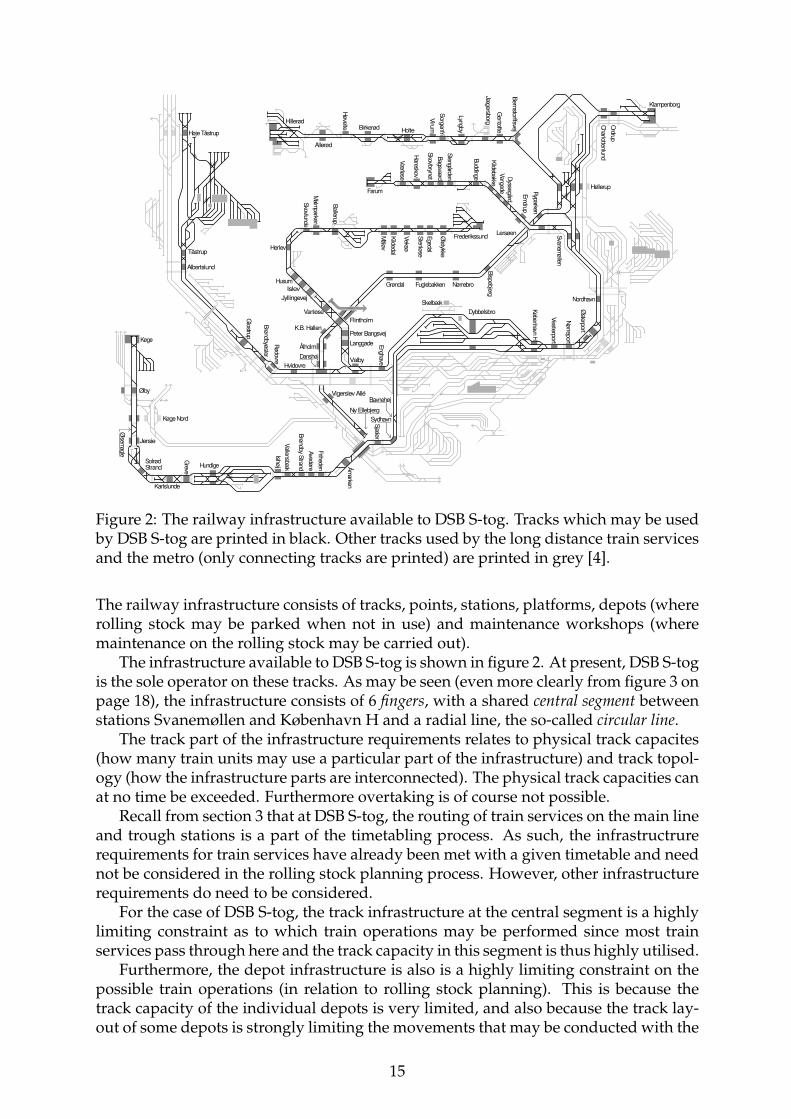
Figure 2: The railway infrastructure available to DSB S-tog. Tracks which may be usedby DSB S-tog are printed in black. Other tracks used by the long distance train servicesand the metro (only connecting tracks are printed) are printed in grey [4].
The railway infrastructure consists of tracks, points, stations, platforms, depots (whererolling stock may be parked when not in use) and maintenance workshops (wheremaintenance on the rolling stock may be carried out).
The infrastructure available to DSB S-tog is shown in figure 2. At present, DSB S-togis the sole operator on these tracks. As may be seen (even more clearly from figure 3 onpage 18), the infrastructure consists of 6 fingers, with a shared central segment betweenstations Svanemøllen and København H and a radial line, the so-called circular line.
The track part of the infrastructure requirements relates to physical track capacites(how many train units may use a particular part of the infrastructure) and track topol-ogy (how the infrastructure parts are interconnected). The physical track capacities canat no time be exceeded. Furthermore overtaking is of course not possible.
Recall from section 3 that at DSB S-tog, the routing of train services on the main lineand trough stations is a part of the timetabling process. As such, the infrastructrurerequirements for train services have already been met with a given timetable and neednot be considered in the rolling stock planning process. However, other infrastructurerequirements do need to be considered.
For the case of DSB S-tog, the track infrastructure at the central segment is a highlylimiting constraint as to which train operations may be performed since most trainservices pass through here and the track capacity in this segment is thus highly utilised.
Furthermore, the depot infrastructure is also is a highly limiting constraint on thepossible train operations (in relation to rolling stock planning). This is because thetrack capacity of the individual depots is very limited, and also because the track lay-out of some depots is strongly limiting the movements that may be conducted with the
15
rolling stock.There are two workshops where maintenance may be carried out, the main work-
shop in Høje Tåstrup and a subsidiary workshop in Hundige. The latter workshopis staffed on demand by a mobile repair crew and is only used in special cases. Allscheduled maintenance tasks are carried out in the main workshop in Høje Tåstrup.Some maintenance tasks may be performed in both workshops, some only in the mainone in Høje Tåstrup.
The location of the depot at København H in relation to the lines defined in thetimetable (see section 5.1.2) means that rolling stock parked here may be put into ser-vice on any line (including the circular line, since both Klampenborg and KøbenhavnH depots serve as depots for this line).
Other infrastructure related requirements are the track usage rules, business rulesstating which track to use for a specific line and direction.
Train movements, that is, the motion, coupling and decoupling of train units are alsogoverned by the infrastructure in four ways:
1. The train control system enforces rules for the train movements. The current traincontrol system is based on external and internal visual signals to which the traindriver has to act, as well as automatic emergency braking if he or she fails todo so. In small parts of the network manual train control is performed using anelectro-mechanical train control system. The other large part of the network hasan automatic system.
Presently, the rules of the existing train control system allows coupling of trainunits depending on whether the train service is a revenue or non-revenue trainservice and whether the last train in the coupling process is arriving from the de-pot or from the main line. Simplified, it is allowed to have any train unit parkedat a platform track and then coupling this train with a train arriving from the de-pot or a non-revenue train arriving from the main line. It is disallowed to couplea train composition running as a revenue train service arriving from the mainline with any train unit parked at the platform track.
A new communication based train control system (CBTC) without external visualsignals will be rolled out from 2014 to 2018. The new system will prove lessrestrictive as to the allowed train movements.
2. In the process of decoupling train units from each other in a train composition,a business rule states that it is disallowed to decouple two parts of a train com-position and letting the part that is going to continue as a revenue train servicedepart before the other part has been driven off into the depot. This is becausepassengers may get confused when parts of the train composition are in service,and other parts not. Furthermore, a movement like the one described must beconducted after the revenue train service has departed. A depot driver may thennot have time to perform another depot movement for the next train service ifthis movement is to occur before the next revenue train service departs.
3. Another business rule states that no coupling or decoupling may take place ona train composition en route from its origin station to its terminal station. Thiswould run the risk of being too time consuming and thus delay other train ser-vices. When changes in the number of train units in a train composition mustbe performed en route, a new set of train units is collectively driven in from the
16
depot to one of the platform tracks. This new set of train units then replaces theold set arriving at the other platform track, and is afterwards collectively driveninto the depot. This type of movement is called a total composition exchange asopposed to a partial composition exchange, in which parts of the train compositionare retained.
4. A business rule states that there can be only one train movement to each couplingor decoupling. As such, it is disallowed to split a train composition into two be-fore driving each of the two parts off into the depot. The opposite movement isalso disallowed. This business rule is in place to enforce simplicity and robust-ness. If more movements for each coupling or decoupling would be allowed, thetrain units would occupy the platform tracks for much longer periods of time,with a higher risk of delaying otherwise uninvolved train services.
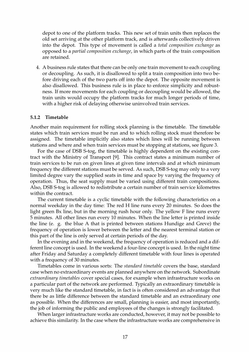
5.1.2 Timetable
Another main requirement for rolling stock planning is the timetable. The timetablestates which train services must be run and to which rolling stock must therefore beassigned. The timetable implicitly also states which lines will be running betweenstations and where and when train services must be stopping at stations, see figure 3.
For the case of DSB S-tog, the timetable is highly dependent on the existing con-tract with the Ministry of Transport [9]. This contract states a minimum number oftrain services to be run on given lines at given time intervals and at which minimumfrequency the different stations must be served. As such, DSB S-tog may only to a verylimited degree vary the supplied seats in time and space by varying the frequency ofoperation. Thus, the seat supply must be varied using different train compositions.Also, DSB S-tog is allowed to redistribute a certain number of train service kilometreswithin the contract.
The current timetable is a cyclic timetable with the following characteristics on anormal weekday in the day time: The red H line runs every 20 minutes. So does thelight green Bx line, but in the morning rush hour only. The yellow F line runs every5 minutes. All other lines run every 10 minutes. When the line letter is printed insidethe line (e. g. the blue A that is printed between stations Hundige and Greve) thefrequency of operation is lower between the letter and the nearest terminal station orthis part of the line is only served at certain periods of the day.
In the evening and in the weekend, the frequency of operation is reduced and a dif-ferent line concept is used. In the weekend a four-line concept is used. In the night timeafter Friday and Saturday a completely different timetable with four lines is operatedwith a frequency of 30 minutes.
Timetables come in various sorts: The standard timetable covers the base, standardcase when no extraordinary events are planned anywhere on the network. Subordinateextraordinary timetables cover special cases, for example when infrastructure works ona particular part of the network are performed. Typically an extraordinary timetable isvery much like the standard timetable, in fact is is often considered an advantage thatthere be as little difference between the standard timetable and an extraordinary oneas possible. When the differences are small, planning is easier, and most importantly,the job of informing the public and employees of the changes is strongly facilitated.
When larger infrastructure works are conducted, however, it may not be possible toachieve this similarity. In the case where the infrastructure works are comprehensive in
17

Figure 3: The graphical representation of the DSB S-tog timetable valid from December2012 to December 2013 for weekdays. Each line is represented by a different colour.There is a different line concept on weekends and at night.
18
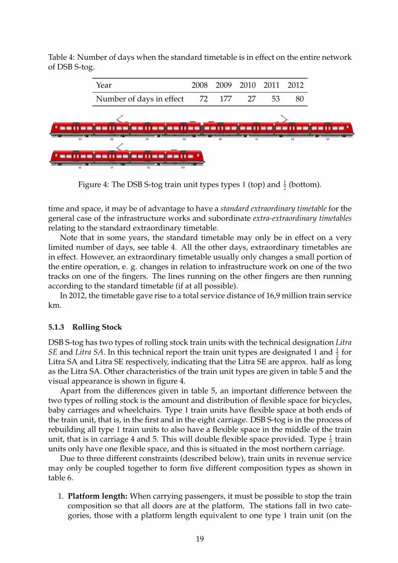
Table 4: Number of days when the standard timetable is in effect on the entire networkof DSB S-tog.
Year 2008 2009 2010 2011 2012
Number of days in effect 72 177 27 53 80
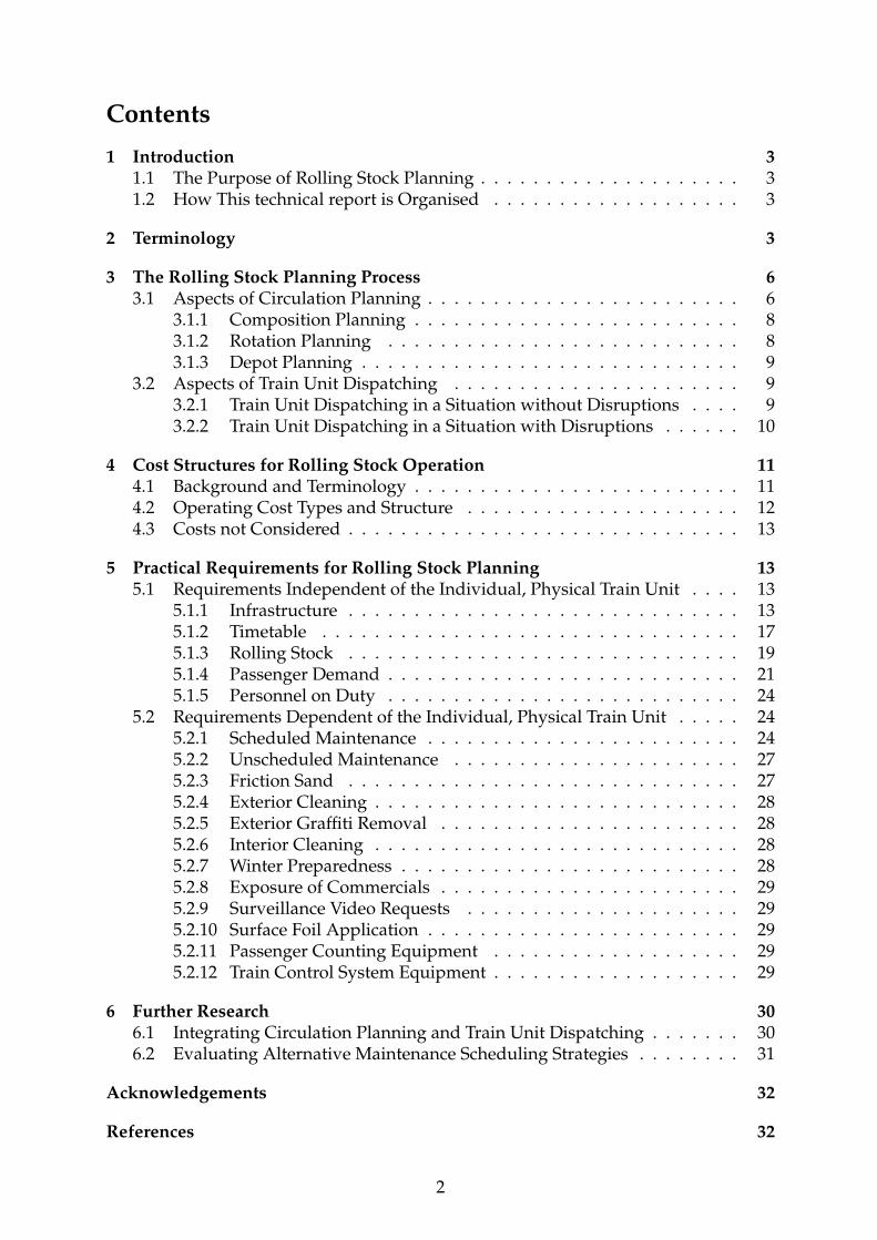
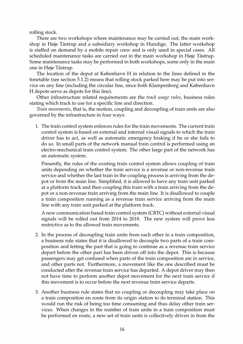
Figure 4: The DSB S-tog train unit types types 1 (top) and 12 (bottom).
time and space, it may be of advantage to have a standard extraordinary timetable for thegeneral case of the infrastructure works and subordinate extra-extraordinary timetablesrelating to the standard extraordinary timetable.
Note that in some years, the standard timetable may only be in effect on a verylimited number of days, see table 4. All the other days, extraordinary timetables arein effect. However, an extraordinary timetable usually only changes a small portion ofthe entire operation, e. g. changes in relation to infrastructure work on one of the twotracks on one of the fingers. The lines running on the other fingers are then runningaccording to the standard timetable (if at all possible).
In 2012, the timetable gave rise to a total service distance of 16,9 million train servicekm.
5.1.3 Rolling Stock
DSB S-tog has two types of rolling stock train units with the technical designation LitraSE and Litra SA. In this technical report the train unit types are designated 1 and 1
2 forLitra SA and Litra SE respectively, indicating that the Litra SE are approx. half as longas the Litra SA. Other characteristics of the train unit types are given in table 5 and thevisual appearance is shown in figure 4.
Apart from the differences given in table 5, an important difference between thetwo types of rolling stock is the amount and distribution of flexible space for bicycles,baby carriages and wheelchairs. Type 1 train units have flexible space at both ends ofthe train unit, that is, in the first and in the eight carriage. DSB S-tog is in the process ofrebuilding all type 1 train units to also have a flexible space in the middle of the trainunit, that is in carriage 4 and 5. This will double flexible space provided. Type 1
2 trainunits only have one flexible space, and this is situated in the most northern carriage.
Due to three different constraints (described below), train units in revenue servicemay only be coupled together to form five different composition types as shown intable 6.
1. Platform length: When carrying passengers, it must be possible to stop the traincomposition so that all doors are at the platform. The stations fall in two cate-gories, those with a platform length equivalent to one type 1 train unit (on the
19
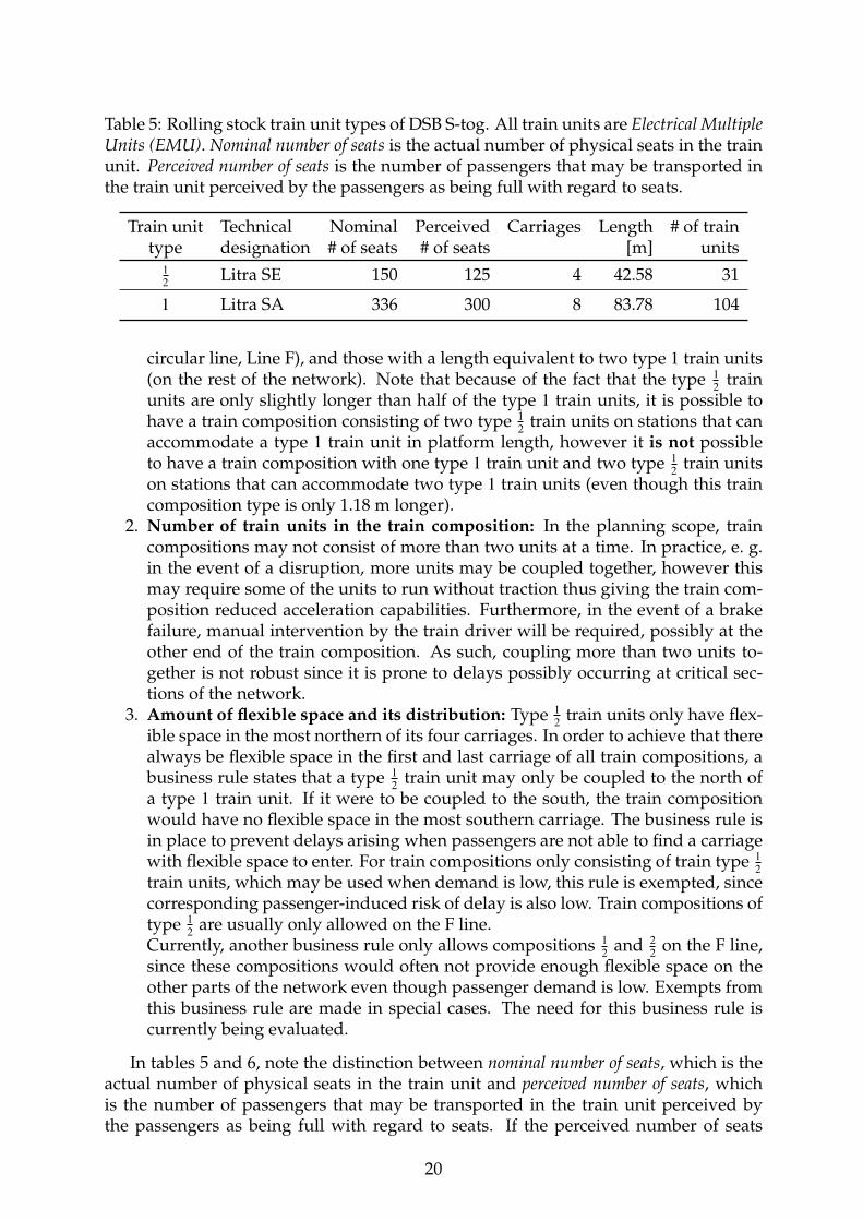
Table 5: Rolling stock train unit types of DSB S-tog. All train units are Electrical MultipleUnits (EMU). Nominal number of seats is the actual number of physical seats in the trainunit. Perceived number of seats is the number of passengers that may be transported inthe train unit perceived by the passengers as being full with regard to seats.
Train unit Technical Nominal Perceived Carriages Length # of traintype designation # of seats # of seats [m] units
12 Litra SE 150 125 4 42.58 31
1 Litra SA 336 300 8 83.78 104
circular line, Line F), and those with a length equivalent to two type 1 train units(on the rest of the network). Note that because of the fact that the type 1
2 trainunits are only slightly longer than half of the type 1 train units, it is possible tohave a train composition consisting of two type 1
2 train units on stations that canaccommodate a type 1 train unit in platform length, however it is not possibleto have a train composition with one type 1 train unit and two type 1
2 train unitson stations that can accommodate two type 1 train units (even though this traincomposition type is only 1.18 m longer).
2. Number of train units in the train composition: In the planning scope, traincompositions may not consist of more than two units at a time. In practice, e. g.in the event of a disruption, more units may be coupled together, however thismay require some of the units to run without traction thus giving the train com-position reduced acceleration capabilities. Furthermore, in the event of a brakefailure, manual intervention by the train driver will be required, possibly at theother end of the train composition. As such, coupling more than two units to-gether is not robust since it is prone to delays possibly occurring at critical sec-tions of the network.
3. Amount of flexible space and its distribution: Type 12 train units only have flex-
ible space in the most northern of its four carriages. In order to achieve that therealways be flexible space in the first and last carriage of all train compositions, abusiness rule states that a type 1
2 train unit may only be coupled to the north ofa type 1 train unit. If it were to be coupled to the south, the train compositionwould have no flexible space in the most southern carriage. The business rule isin place to prevent delays arising when passengers are not able to find a carriagewith flexible space to enter. For train compositions only consisting of train type 1
2train units, which may be used when demand is low, this rule is exempted, sincecorresponding passenger-induced risk of delay is also low. Train compositions oftype 1
2 are usually only allowed on the F line.Currently, another business rule only allows compositions 1
2 and 22 on the F line,
since these compositions would often not provide enough flexible space on theother parts of the network even though passenger demand is low. Exempts fromthis business rule are made in special cases. The need for this business rule iscurrently being evaluated.
In tables 5 and 6, note the distinction between nominal number of seats, which is theactual number of physical seats in the train unit and perceived number of seats, whichis the number of passengers that may be transported in the train unit perceived bythe passengers as being full with regard to seats. If the perceived number of seats
20
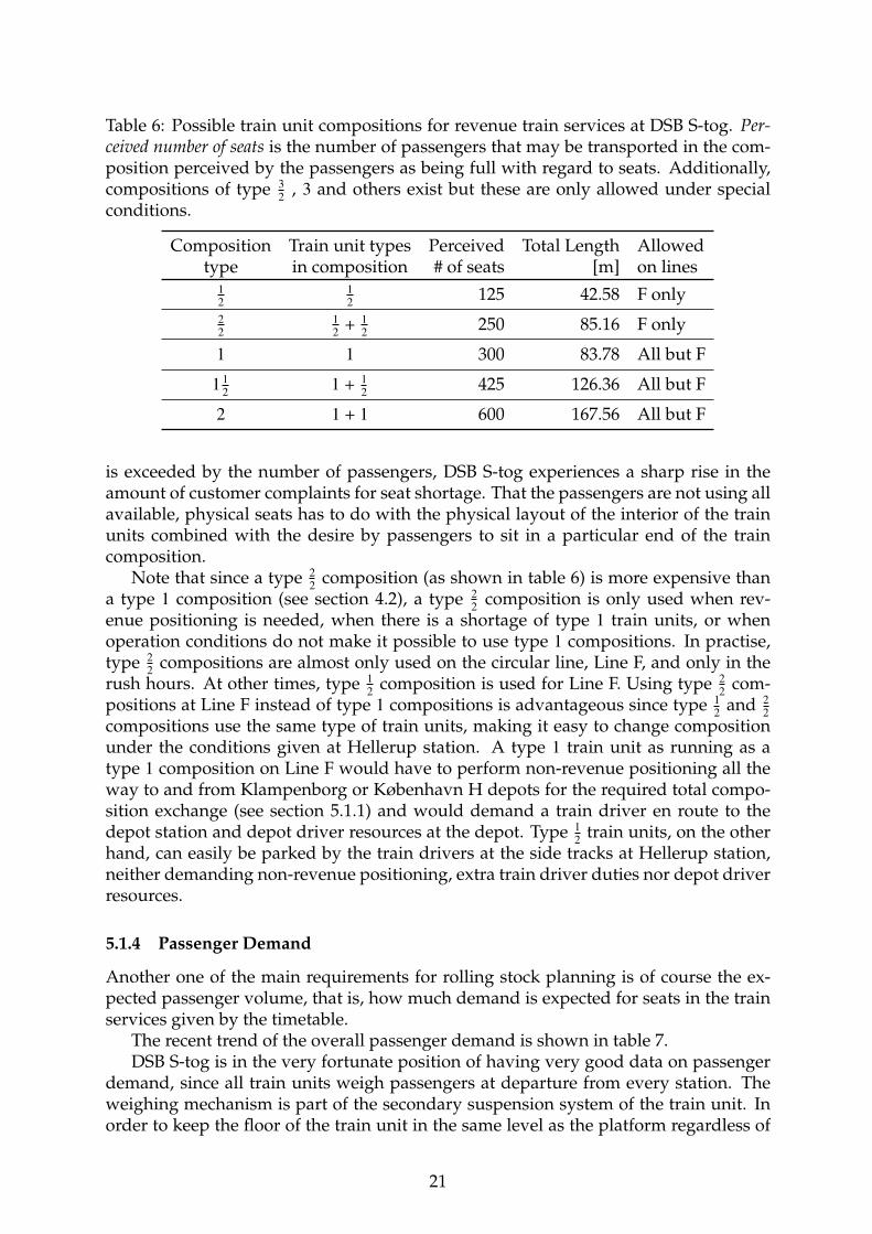
Table 6: Possible train unit compositions for revenue train services at DSB S-tog. Per-ceived number of seats is the number of passengers that may be transported in the com-position perceived by the passengers as being full with regard to seats. Additionally,compositions of type 3
2 , 3 and others exist but these are only allowed under specialconditions.
Composition Train unit types Perceived Total Length Allowedtype in composition # of seats [m] on lines
12
12 125 42.58 F only
22
12 + 1
2 250 85.16 F only
1 1 300 83.78 All but F
112 1 + 1
2 425 126.36 All but F
2 1 + 1 600 167.56 All but F
is exceeded by the number of passengers, DSB S-tog experiences a sharp rise in theamount of customer complaints for seat shortage. That the passengers are not using allavailable, physical seats has to do with the physical layout of the interior of the trainunits combined with the desire by passengers to sit in a particular end of the traincomposition.
Note that since a type 22 composition (as shown in table 6) is more expensive than
a type 1 composition (see section 4.2), a type 22 composition is only used when rev-
enue positioning is needed, when there is a shortage of type 1 train units, or whenoperation conditions do not make it possible to use type 1 compositions. In practise,type 2
2 compositions are almost only used on the circular line, Line F, and only in therush hours. At other times, type 1
2 composition is used for Line F. Using type 22 com-
positions at Line F instead of type 1 compositions is advantageous since type 12 and 2
2compositions use the same type of train units, making it easy to change compositionunder the conditions given at Hellerup station. A type 1 train unit as running as atype 1 composition on Line F would have to perform non-revenue positioning all theway to and from Klampenborg or København H depots for the required total compo-sition exchange (see section 5.1.1) and would demand a train driver en route to thedepot station and depot driver resources at the depot. Type 1
2 train units, on the otherhand, can easily be parked by the train drivers at the side tracks at Hellerup station,neither demanding non-revenue positioning, extra train driver duties nor depot driverresources.
5.1.4 Passenger Demand
Another one of the main requirements for rolling stock planning is of course the ex-pected passenger volume, that is, how much demand is expected for seats in the trainservices given by the timetable.
The recent trend of the overall passenger demand is shown in table 7.DSB S-tog is in the very fortunate position of having very good data on passenger
demand, since all train units weigh passengers at departure from every station. Theweighing mechanism is part of the secondary suspension system of the train unit. Inorder to keep the floor of the train unit in the same level as the platform regardless of
21
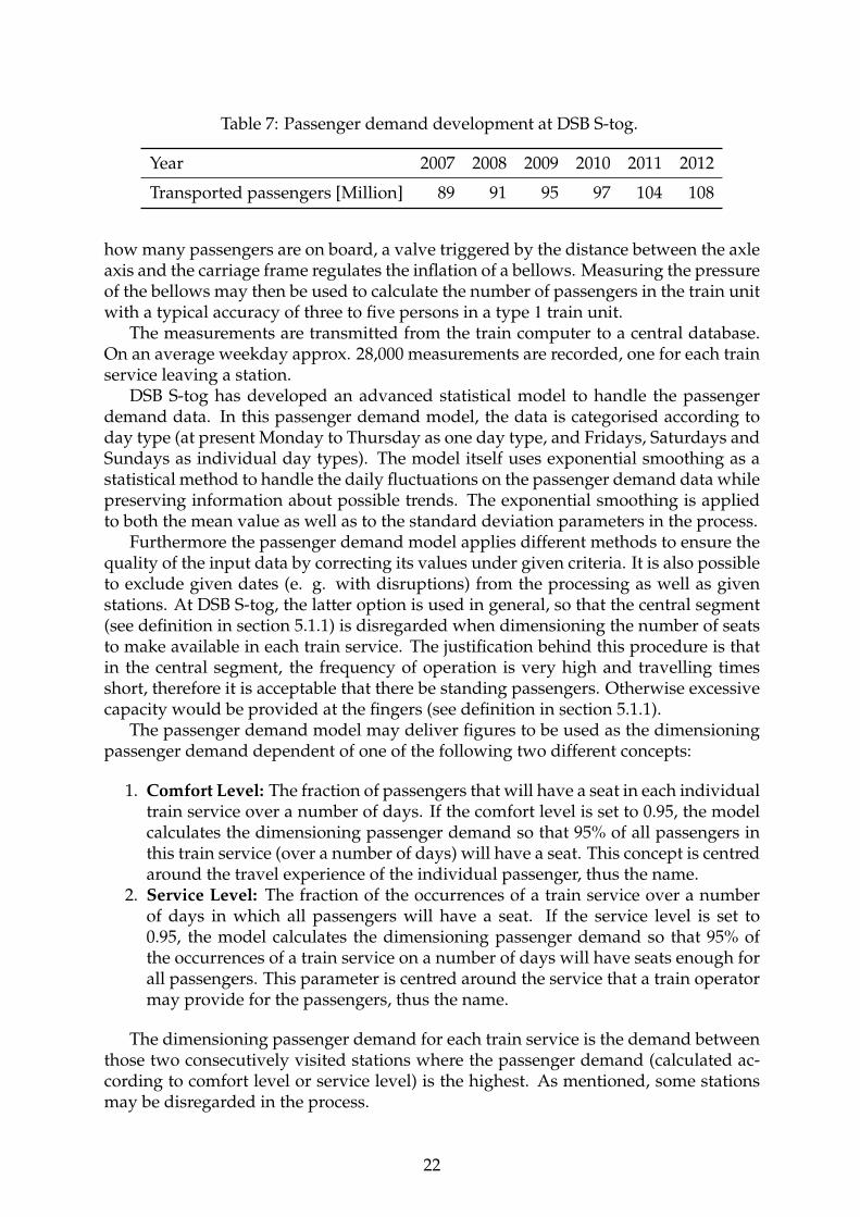
Table 7: Passenger demand development at DSB S-tog.
Year 2007 2008 2009 2010 2011 2012
Transported passengers [Million] 89 91 95 97 104 108
how many passengers are on board, a valve triggered by the distance between the axleaxis and the carriage frame regulates the inflation of a bellows. Measuring the pressureof the bellows may then be used to calculate the number of passengers in the train unitwith a typical accuracy of three to five persons in a type 1 train unit.
The measurements are transmitted from the train computer to a central database.On an average weekday approx. 28,000 measurements are recorded, one for each trainservice leaving a station.
DSB S-tog has developed an advanced statistical model to handle the passengerdemand data. In this passenger demand model, the data is categorised according today type (at present Monday to Thursday as one day type, and Fridays, Saturdays andSundays as individual day types). The model itself uses exponential smoothing as astatistical method to handle the daily fluctuations on the passenger demand data whilepreserving information about possible trends. The exponential smoothing is appliedto both the mean value as well as to the standard deviation parameters in the process.
Furthermore the passenger demand model applies different methods to ensure thequality of the input data by correcting its values under given criteria. It is also possibleto exclude given dates (e. g. with disruptions) from the processing as well as givenstations. At DSB S-tog, the latter option is used in general, so that the central segment(see definition in section 5.1.1) is disregarded when dimensioning the number of seatsto make available in each train service. The justification behind this procedure is thatin the central segment, the frequency of operation is very high and travelling timesshort, therefore it is acceptable that there be standing passengers. Otherwise excessivecapacity would be provided at the fingers (see definition in section 5.1.1).
The passenger demand model may deliver figures to be used as the dimensioningpassenger demand dependent of one of the following two different concepts:
1. Comfort Level: The fraction of passengers that will have a seat in each individualtrain service over a number of days. If the comfort level is set to 0.95, the modelcalculates the dimensioning passenger demand so that 95% of all passengers inthis train service (over a number of days) will have a seat. This concept is centredaround the travel experience of the individual passenger, thus the name.
2. Service Level: The fraction of the occurrences of a train service over a numberof days in which all passengers will have a seat. If the service level is set to0.95, the model calculates the dimensioning passenger demand so that 95% ofthe occurrences of a train service on a number of days will have seats enough forall passengers. This parameter is centred around the service that a train operatormay provide for the passengers, thus the name.
The dimensioning passenger demand for each train service is the demand betweenthose two consecutively visited stations where the passenger demand (calculated ac-cording to comfort level or service level) is the highest. As mentioned, some stationsmay be disregarded in the process.
22

0
10
20
30
40
50
60
70
Weekdays Fridays Saturdays Sundays
Num
ber o
f tra
ins
dem
ande
d w
ith s
peci
fied
train
com
posi
tion
type
Train composition type 1/2Train composition type 1
Train composition type 1 1/2Train composition type 2
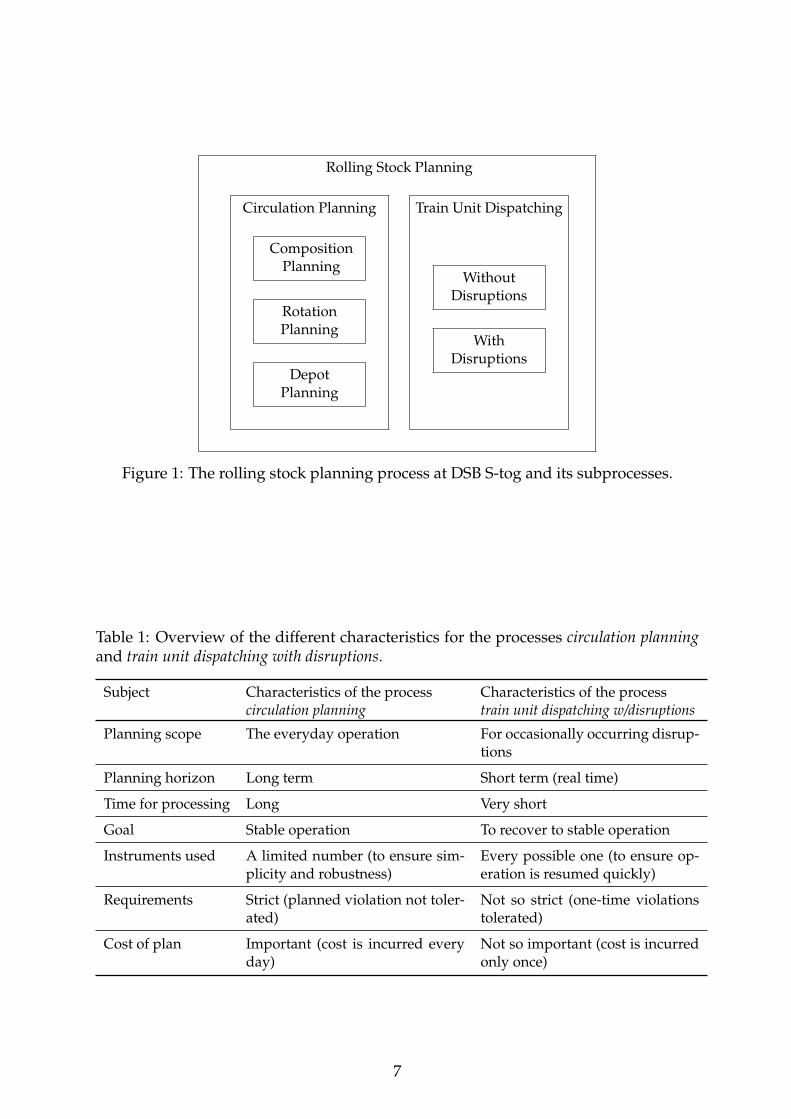
Figure 5: Passenger demand by day type and time expressed as demand for numberof specific train composition types, as defined in table 6 on page 21. The compositiontypes are stacked in the figure, their common total indicating the total number of trainservices in service by day type and time. The suboptimal train composition type 2
2 isnot shown.
Figure 5 shows a graphical representation of current passenger demand data. Herethe passenger demand is converted to train composition type according to the seatcapacity of the individual train unit types, see table 6. As may be seen from the figure,the train composition type 2 with the highest capacity is only demanded in the rushhours on weekdays and Fridays. The same goes for the train composition type 11
2 , thetrain composition type with the second highest capacity, the only difference being thata few train services at Sunday afternoon also demand this kind of composition.
When comparing the demand for the composition 12 in figure 5, to the amount of
short train units available to DSB S-tog as shown in table 5, page 20, one can see thatthe demand for half-length train units is often much higher than the number of half-length train units available. In most of these cases DSB S-tog is forced to assign full-length train units to the train services thus providing excess seat capacity and havingto bear the extra cost.
Since 2010 it has been free of charge to bring along bicycles in all DSB S-tog trainservices. This has meant an increase in passenger demand for flexible space wherebicycles may be parked. This is something that rolling stock planning may need totake into account in the future. DSB S-tog is in the process of rebuilding all train unittype 1 train units to also have a large flexible space in the middle of the train unit. Inthis way the flexible space capacity will be doubled for all train unit type 1 and the
23
flexible space distribution will be more even in the entire length of train compositionsconsisting of train unit type 1 train units.
When a rolling stock plan does not provide enough seats to meet passenger de-mand, the consequences for the train operator are risk of delays due to overcrowd-ing, customer dissatisfaction and customer complaints. All of these consequences mayeventually have negative economic implications.
If on the other hand, a rolling stock plan provides too many seats, this also hasnegative economic implications in that the surplus seats add an extra cost at virtuallyno extra gain.
Finally, there is also a political demand from society that DSB S-tog maintains anefficient operation. Only by doing so may DSB S-tog gain future transport contracts.
This underlines the importance of having a rolling stock plan that meets passengerdemand as closely as possible.
5.1.5 Personnel on Duty
In order to couple and decouple train units and to drive train units into the depot forparking and back to the platform for service, a designated crew of depot drivers operateat DSB S-tog. Each depot has a number of depot drivers on duty at different hours ofthe week, and any rolling stock plan must of course adhere to this number, and notdemand more depot operations than it is possible to conduct with the crew on duty.
How many depot drivers are hired and when they should be on duty is decidedevery time a standard timetable is planned (see definition in section 5.1.2), based onthe demand in the corresponding rolling stock plan. Extraordinary timetables mustthen adhere to then number of depot drivers hired and their duties for the standardtimetable.
Recently, the train drivers, that is, the employee group driving train services inscheduled passenger service as well as non-revenue positioning train services, do per-form some of the operations previously conducted by the depot drivers, for stationsHillerød, Farum, Køge and Frederikssund in the morning and evening on weekends.This also needs to be integrated into the rolling stock planning process.
5.2 Requirements Dependent of the Individual, Physical Train Unit
This section describes the requirements for the rolling stock planning process that aredependent of (that is directly related to) the individual physical train unit. For ex-ample, maintenance requirements are related to the individual physical train unit: Ifa train unit has a break down, then maintenance must be carried out on exactly thattrain unit.
5.2.1 Scheduled Maintenance
As stated by the Danish Transport Authority, each train unit belonging to DSB S-togmust undergo scheduled maintenance at given intervals.
A standard maintenance check of the individual train unit must be scheduled ev-ery 50,000 km of service distance. The duration of a scheduled standard maintenancecheck is approx. 4 hours.
24
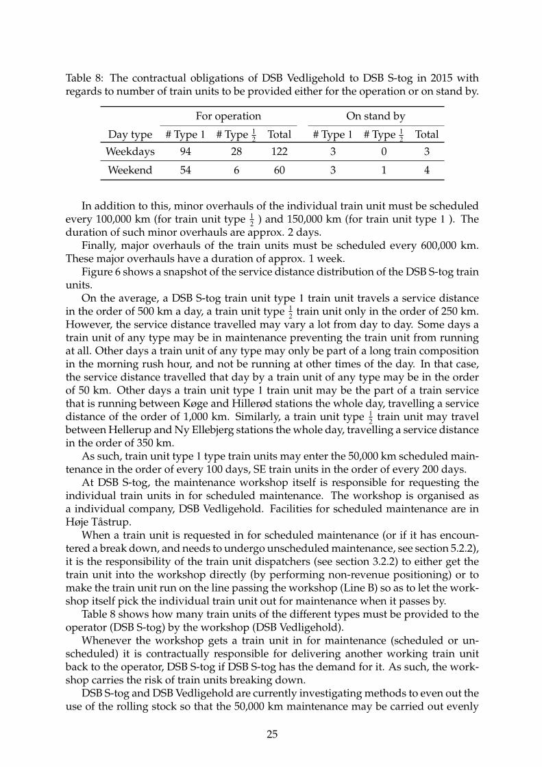
Table 8: The contractual obligations of DSB Vedligehold to DSB S-tog in 2015 withregards to number of train units to be provided either for the operation or on stand by.
For operation On stand by
Day type # Type 1 # Type 12 Total # Type 1 # Type 1
2 Total
Weekdays 94 28 122 3 0 3
Weekend 54 6 60 3 1 4
In addition to this, minor overhauls of the individual train unit must be scheduledevery 100,000 km (for train unit type 1
2 ) and 150,000 km (for train unit type 1 ). Theduration of such minor overhauls are approx. 2 days.
Finally, major overhauls of the train units must be scheduled every 600,000 km.These major overhauls have a duration of approx. 1 week.
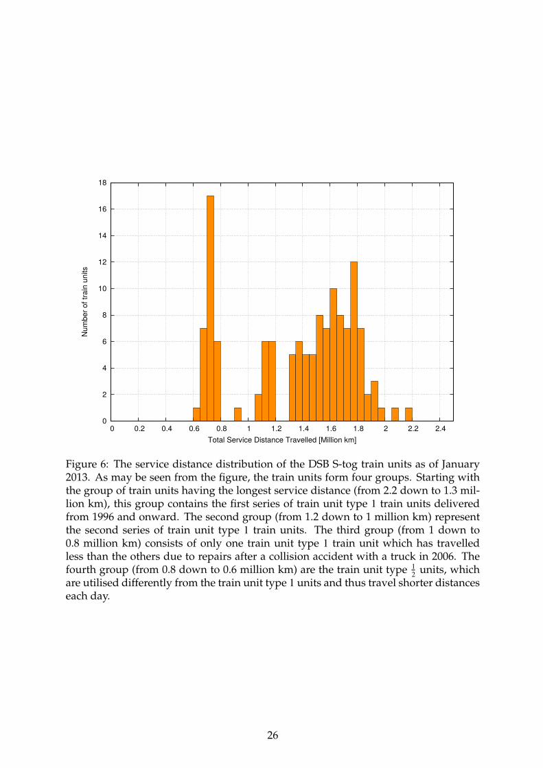
Figure 6 shows a snapshot of the service distance distribution of the DSB S-tog trainunits.
On the average, a DSB S-tog train unit type 1 train unit travels a service distancein the order of 500 km a day, a train unit type 1
2 train unit only in the order of 250 km.However, the service distance travelled may vary a lot from day to day. Some days atrain unit of any type may be in maintenance preventing the train unit from runningat all. Other days a train unit of any type may only be part of a long train compositionin the morning rush hour, and not be running at other times of the day. In that case,the service distance travelled that day by a train unit of any type may be in the orderof 50 km. Other days a train unit type 1 train unit may be the part of a train servicethat is running between Køge and Hillerød stations the whole day, travelling a servicedistance of the order of 1,000 km. Similarly, a train unit type 1
2 train unit may travelbetween Hellerup and Ny Ellebjerg stations the whole day, travelling a service distancein the order of 350 km.
As such, train unit type 1 type train units may enter the 50,000 km scheduled main-tenance in the order of every 100 days, SE train units in the order of every 200 days.
At DSB S-tog, the maintenance workshop itself is responsible for requesting theindividual train units in for scheduled maintenance. The workshop is organised asa individual company, DSB Vedligehold. Facilities for scheduled maintenance are inHøje Tåstrup.
When a train unit is requested in for scheduled maintenance (or if it has encoun-tered a break down, and needs to undergo unscheduled maintenance, see section 5.2.2),it is the responsibility of the train unit dispatchers (see section 3.2.2) to either get thetrain unit into the workshop directly (by performing non-revenue positioning) or tomake the train unit run on the line passing the workshop (Line B) so as to let the work-shop itself pick the individual train unit out for maintenance when it passes by.
Table 8 shows how many train units of the different types must be provided to theoperator (DSB S-tog) by the workshop (DSB Vedligehold).
Whenever the workshop gets a train unit in for maintenance (scheduled or un-scheduled) it is contractually responsible for delivering another working train unitback to the operator, DSB S-tog if DSB S-tog has the demand for it. As such, the work-shop carries the risk of train units breaking down.
DSB S-tog and DSB Vedligehold are currently investigating methods to even out theuse of the rolling stock so that the 50,000 km maintenance may be carried out evenly
25
0
2
4
6
8
10
12
14
16
18
0 0.2 0.4 0.6 0.8 1 1.2 1.4 1.6 1.8 2 2.2 2.4
Num
ber o
f tra
in u
nits
Total Service Distance Travelled [Million km]
Figure 6: The service distance distribution of the DSB S-tog train units as of January2013. As may be seen from the figure, the train units form four groups. Starting withthe group of train units having the longest service distance (from 2.2 down to 1.3 mil-lion km), this group contains the first series of train unit type 1 train units deliveredfrom 1996 and onward. The second group (from 1.2 down to 1 million km) representthe second series of train unit type 1 train units. The third group (from 1 down to0.8 million km) consists of only one train unit type 1 train unit which has travelledless than the others due to repairs after a collision accident with a truck in 2006. Thefourth group (from 0.8 down to 0.6 million km) are the train unit type 1
2 units, whichare utilised differently from the train unit type 1 units and thus travel shorter distanceseach day.
26
distributed in time so as not to cause bottlenecks in the workshop. Future rolling stockplans may need to take this into account.
5.2.2 Unscheduled Maintenance
Apart from the scheduled maintenance mentioned above, a train unit may break downat any time and require immediate (and thus unscheduled) maintenance. Breakdownsare grouped in one of the following six categories depending on the nature of the break-down. The time before a break down has to be remedied depends on the category.
• Category A is for breakdowns of major concern, preventing the train unit ofcontinuing in passenger service, e. g. when two consecutive sets of doors areblocked. In this case, in the event of an emergency, the train unit may not beevacuated according to the safety regulations. For this reason it is not allowed inpassenger service, and must undergo maintenance immediately;
• Category B is for breakdowns of medium concern needing to be remedied rel-atively quickly, e. g. when a train unit is externally covered in graffiti. In thiscategory the train unit must undergo maintenance, in this case exterior graffitiremoval, within 3 hours;
• Category B1 is for breakdowns of medium concern used when the need for aremedy is less urgent, e. g. a heating system failure. In this category the trainunit must undergo maintenance before 0300h the next day;
• Category C is for breakdowns of minor concern needing to be remedied within72 hours, e. g. one set of blocked doors;
• Category C1 is for breakdowns of minor concern that only need to be remediedwithin one week, e. g. a compressor fault. The train units have hydraulic brakesindependent of the pneumatic system;
• Category D is for breakdowns which have no impairing effect on the function-ality of the train unit, e. g. an interior overhead light that is not functioning.Breakdowns of this category can wait until the train unit goes into maintenancefor other reasons.
In addition to the main workshop in Høje Tåstrup and the subsidiary workshop inHundige, DSB Vedligehold also has a mobile repair crew that may head out to remedybroken down train units at any given location at any time.
5.2.3 Friction Sand
In order to enhance friction on tracks made slippery by fallen leaves etc., the trainunits have equipment installed to disperse sand on the tracks in front of the some ofthe wheels. The sand tanks need to be filled to a certain level, otherwise a category Abreakdown of the train unit is registered (see definition section 5.2.2) with an additionalspeed restriction of 60 km/h. The filling level of the sand tanks must be checked every10,000 km of service distance.
Friction sand can be refilled at the workshops at Høje Tåstrup and Hundige andnew facilities are under selection. The refilling of sand is obstructed by any platformstructure beside both sides of the tracks. On the other hand, a surface upon which thefriction sand delivering car may drive must be provided on both sides of the tracks,limiting the number of candidate tracks for new facilities. In addition, friction sandmust be stored free from frost and humidity.
27
5.2.4 Exterior Cleaning
The exterior cleaning of the train units is conducted automatically in tunnel shapedcleaning facilities which the train compositions pass through at a speed of 3 km/h.Facilities are in Høje Tåstrup and Hundige.
It is the goal of DSB S-tog to clean the exterior of all train units every 15 days. Sincethe exterior graffiti removal facility in Høje Tåstrup is on the same track as the facilitiesfor exterior cleaning, this goal can not always be achieved, since the removal of externalgraffiti has precedence.
5.2.5 Exterior Graffiti Removal
Removing graffiti from the outside of a train unit may take anything from half an hourto an entire day depending on the area of the train unit covered and in particular howmuch time has elapsed since the graffiti was painted onto the train unit. The timefactor is one of the reasons for graffiti being a category B break down (see definition insection 5.2.2). Graffiti removal is performed by DSB S-tog staff in facilities in Hundigeand Høje Tåstrup.
5.2.6 Interior Cleaning
The interior cleaning of the train units is performed in on a daily basis in the depots.The cleaning is performed by designated cleaning personnel and also by the depotdrivers, both employee groups are DSB S-tog staff. Train units for day train servicesare cleaned at night and train units for night train services in the morning.
In order to facilitate day to day interior cleaning, a business rule states that trainunits to enter night time service must be put into service by performing a train com-position exchange (see definition in section 5.1.1) with newly cleaned train units. Assuch, a train composition for a night train service will always consist of newly cleanedtrain units. A similar business rule states that, in the morning, train units in a nighttrain service must be driven into the depot without being split up. This ensures thattrain compositions for the day train services are also newly cleaned.
The two business rules are in place to make sure that the cleaning standard is ashigh as possible at all times and to even out the workload of the personnel cleaning. Itis well known that train units with a low cleaning standard attract much more dirt andgarbage than train units with a high level of cleanliness.
As of 2012, DSB S-tog is cleaning the interior of the train units according to howmuch in need of cleaning the individual train units are. This is administered by thecleaning crews themselves in order to achieve employee empowerment. Prior to this,the train units were cleaned according to a schedule.
Internal graffiti is cleaned by DSB S-tog staff and may be performed at any depot.
5.2.7 Winter Preparedness
In order to prevent ice from accumulating underneath the train units in winter time,the undercarriage of all train units must be treated with anti ice fluid every 6 dayswhen the weather is cold. Facilities for doing so are at Høje Tåstrup and KøbenhavnH. The duration of the anti ice treatment itself is one minute for a train unit type 1
2 andtwo minutes for a train unit type 1 , however due to the track layout, only 6 train unitsmay be treated per hour in each of the two facilities.
28

5.2.8 Exposure of Commercials
The train units of DSB S-tog all have commercials mounted internally. Some trainunits also have externally mounted commercials in the form of adhesive foil. In orderto expose commercials in certain geographic regions, it may be required that a certaintrain unit be running on a particular line on a particular set of days.
This may induce the problem of favourite train units, that is, train units that theoperator may want to have running as much as possible. However, in this way, sometrain units may run more than others, possibly creating maintenance bottlenecks whenthe 50,000 km maintenance is to take place at the same time for multiple train units.
5.2.9 Surveillance Video Requests
All train units of DSB S-tog have 24 hour video surveillance. The video recordings ofall cameras in a train unit are stored on hard disks in the train unit and may be re-trieved for investigative purposes upon order by the Police. At present, the retrievingof recordings takes place in the train unit in which the recording was made. WhenPolice requests a video recording from a particular train unit, this train unit must bedriven into the main workshop in Høje Tåstrup for video retrieval within a week fromthe time of the event the Police wants to investigate. Otherwise the recording is over-written. In special cases the retrieving of video recordings may be performed by theDSB S-tog mobile repair crew in any of the depots. DSB S-tog is working on a so-lution to make it possible to remotely download the video recordings in the future,thus making the rolling stock planning free of needing to take this requirement intoconsideration.
5.2.10 Surface Foil Application
The train units of DSB S-tog are all in the process of being covered by a protectivesurface foil. This foil has better resistance to graffiti and may, in the event of damage,be replaced much faster and cheaper than the alternative - a conventional repaint ofthe train unit. In addition to this foil, some train units have a commercial foil appliedon top of the protective foil. The commercial foil is replaced at irregular intervals.
Facilities for foiling are in Hundige. The foiling itself is performed by an externalcompany.
5.2.11 Passenger Counting Equipment
Some of the train units, 12 of the train unit type 1 and 4 of the train unit type 12 have
infrared passenger counting equipment installed. The infrared counting system is usedto count the passengers getting on and off. The data generated is used for modellingpurposes. In order to achieve good data samples for modelling, the train units withinfrared counting equipment may need to run as specific train services on specific days.
5.2.12 Train Control System Equipment
As of 2014, when the new train control system will be rolled out on parts of the net-work, special equipment inside the train units will be required to run on the parts of
29
the network that have the new train control system. Train units not having this equip-ment installed will not be allowed to run on the parts of the network that are controlledby the new train control system.
6 Further Research
This technical report serves as basis for the further research in the current Ph. D.project.
One topic of further research on automating manual procedures for repairing infea-sible rolling stock plans. Based on manual procedures used today by the planners, asimple repair heuristic could be proposed to repair infeasible rolling stock plans madewith the current system.
Another topic of further research is in constructing an integrated rolling stock plan-ning model, integrating the subprocesses of the circulation planning, that is, the com-position, rotation and depot planning subprocesses.
A potential third topic of further research involves the the prospect of integratingthe processes circulation planning and train unit dispatching, processes that are nowtreated separately at DSB S-tog. This topic may be within scope of the current Ph. D.project and a brief outlook is presented in section 6.1 below.
A potential fourth topic of further research relates to the possible maintenancestrategies employed by DSB S-tog inspired from other passenger train operators. Thisis treated in section 6.2 below, but is considered outside the scope of the current Ph. D.project. However, should the maintenance strategies of DSB S-tog change, this will bea change to the requirements that this Ph. D. will need to take into account.
6.1 Integrating Circulation Planning and Train Unit Dispatching
The idea of splitting the process of rolling stock planning in circulation planning andtrain unit dispatching at DSB S-tog is probably historically rooted. At the time whenplanning was conducted using paper and pencil, this may well have been a very goodidea, since the circulation plans may have been produced well in advance thus givingthe planners the needed time to produce them. Also the structure of the planning canbe kept so simple it is easy to conduct, and to inform the involved parties when done.
In the age of automatic planning tools, however, one should ask this question: Doesit make sense to make a detailed long term circulation plan stretching a whole monthinto the future, when reality demands changes to train unit dispatching only a fewhours into the plan?
The posit is that if the processes for both circulation planning and train unit dis-patching may be automated and integrated into each other, a new, possibly simplerway of performing rolling stock planning may be conducted. In this new form thereis no need for the abstraction of virtual train units and the planning horizon may bevery short (perhaps even real time). As such, there will be no need for the manualdispatching step of assigning physical train units to virtual ones.
In fact, recent research in related models for airline crew scheduling shows thatthe cost of a plan may be reduced with up to 9% if the pairing step is skipped [7]. Thepairing step in airline crew scheduling is analogous to planning with virtual train unitsfor rolling stock planning. Pairing is when individual duties are aggregated to tours of
30
duty. The tours of duty are then assigned to individual crew members. When this stepis skipped, the individual duties are assigned directly to the crew members.
The pairing aggregation step has been performed up until now to reduce complex-ity of the airline crew scheduling problem.
For rolling stock planning, the analogy to skipping the pairing step would be todirectly assign physical train units to individual train services, as opposed to assigningvirtual train units to aggregated train services, and then assigning physical train unitsto the virtual ones.
Speaking in analogies, one could say, that one can fill more small stones into abucket if one puts one small stone in at a time, than if one glues together the smallstones to big lumps, and then attempts to fit the big lumps into the bucket.
Another aspect is the planning time span. Traditionally, rolling stock planning atDSB S-tog is conducted with a time span of 7 to 18 days, typically. Recent researchin related topics (hump yard sorting and scheduling) [2], however, shows that thereis only a little gain in producing a combined plan for a longer period as opposed toproducing individual, daily plans for each of the days in the given period and lettingthe finishing conditions of each day form the starting conditions for the calculation ofthe next.
Speaking in analogies one could say, that only a few problems are “bulldozed” intothe future by doing so, and if disruptions are occuring anyway, which they are, theeffect of makeing a plan with a long time span are negligible.
One potential difficulty in integrating rolling stock planning and train unit dis-patching processes may occur if only parts of the different processes are automated.If the rolling stock planning process is automated and plans are produced on a veryshort time horizon, these plans may prove very difficult to handle manually in the caseof a disruption, since the plans may not neccessarily contain the structures built intothe manual plans today making them easy to handle manually.
Investigations must show if the realisation of these ideas of integration (to whatever degree) may prove beneficial to DSB S-tog.
6.2 Evaluating Alternative Maintenance Scheduling Strategies
Different train operators have different maintenance scheduling strategies. Up untilnow it has been the strategy of DSB S-tog and DSB Vedligehold to use each train unitas long as possible before conducting maintenance for that particular train unit. A trainunit thus only enters maintenance when it has been running for 50,000 km since thelast time, or of course, if it breaks down before that limit is reached.
When the train unit enters maintenance at DSB Vedligehold, typically nearly everypossible maintenance task is carried out for that particular train unit. As such, the trainunit may be as good as new when it rolls out from the workshop after maintenance. Therationale for this strategy is to keep the number of maintenance stops for each trainunit to a minimum. In other words, the strategy is: Let’s fix everything now the train unitis here!
Other train operators have different maintenance scheduling strategies. At SBB inSwitzerland for instance, each train unit is typically maintained after much less servicedistance [8]. Also the individual maintenance stops are typically shorter than at DSBS-tog. In other words, the strategy is: Let’s fix what we can when we can!
Using this strategy, the train unit may not at all be as good as new when it leavesmaintenance, however since the general level of maintenance of all train units is higher
31
(since the time since each train unit has been looked over is much shorter), the posit isthat fewer break downs are encountered.
Other train operators again may have different conditions that influence their main-tenance scheduling. At DB S-Bahn Berlin, maintenance may be scheduled after as littleas 600 km (compared to that of 50,000 km at DSB S-tog) due to technical issues withthe rolling stock [6]. Making feasible rolling stock rotation plans under such conditionsmay well be quite a challenge.
Investigations must show if another maintenance scheduling strategy following adifferent rationale than today may prove an advantage to DSB S-tog.
Acknowledgements
The current Ph. D. project is supervised by Professor Jesper Larsen, DTU, Julie Jes-persen Groth, DSB, and Marco Laumanns, IBM.
References
[1] Arianna Alfieri, Rutger Groot, Leo Kroon, and Alexander Schrijver. Efficient Circu-lation of Railway Rolling Stock. Transportation Science, 40(3):378–391, August 2006.
[2] Markus Bohlin. Personal communication, September 2013.
[3] Richard Freling, Ramon M. Lentink, Leo G. Kroon, and Dennis Huisman. Shuntingof Passenger Train Units in a Railway Station. Transportation Science, 39(2):261–272,May 2005.
[4] Henning Makholm. A collection of track maps for Danish railways, track map A,2012.
[5] Matias S Rasmussen, Richard M Lusby, David M Ryan, and Jesper Larsen. Subse-quence Generation for the Airline Crew Pairing Problem. Technical Report May,Technical University of Denmark, DTU Management Engineering, 2011.
[6] S-Bahn-Berlin. Personal communication, December 2011.
[7] Mohammed Saddoune, Guy Desaulniers, Issmail Elhallaoui, and François Soumis.Integrated Airline Crew Pairing and Crew Assignment by Dynamic Constraint Ag-gregation. Transportation Science, 46(1):39–55, February 2012.
[8] Schweizerische Bundesbahnen SBB. Personal communication, December 2011.
[9] Trafikministeriet. Kontrakt mellem Trafikministeriet og DSB S-tog a/s om S-togstrafikken udført som offentlig service i perioden 2005-2014, 2004.
32