roller chain division industrial plastic chains - u.s. tsubaki · pdf fileindustrial plastic...
TRANSCRIPT

3.25"
1.50"
0.531"
0.281"
0.157"
Industrial Plastic ChainsSPECIFICATIONS AND SELECTION GUIDELINES
Roller Chain Division
U.S. Tsubaki, Inc.
1.50"

SPECIFICATIONS AND SELECTION GUIDELINES
2
RS Plastic Chain 3–5
Specifications ......................................................................................................................................3-4
Availability Matrix....................................................................................................................................5
Corrosion Resistance Guide...................................................................................................................5
Clip-Top Chain 6
Specifications .........................................................................................................................................6
Availability Matrix....................................................................................................................................6
Top Chain 7-9
Specifications .....................................................................................................................................7–8
Availability Matrix....................................................................................................................................9
Corrosion Resistance Guide...................................................................................................................9
Poly-Steel Chain 10-11
Specifications .......................................................................................................................................10
Availability Matrix..................................................................................................................................10
Corrosion Resistance Guide.................................................................................................................11
Roller Table Chain 12-13
RT Type Specifications .........................................................................................................................12
ST Type Specifications .........................................................................................................................13
Selection Guidelines 14–23
Conveyor Design ..................................................................................................................................17
Selection Procedure for Roller Table Chain ..........................................................................................19
General Engineering Information .........................................................................................................21
This information is intended to provide general guidelines for conveyor chain selection. Consult U.S. Tsubaki for specificapplication problems.

RS PLASTIC CHAIN
3
RS35P: 0.630"
RS40P: 0.906"
RS50P: 1.000"
RS60P: 1.299"
"A" of RS35P = (Sprocket Pitch Diameter)
– 0.157" 2
"A" of RS40P = (Sprocket Pitch Diameter)
– 0.236" 2
"A" of RS50P = (Sprocket Pitch Diameter)
– 0.276" 2
"A" of RS60P = (Sprocket Pitch Diameter)
– 0.335" 2
Max. Allowable Tension (lbs.)
Chain No. Pitch Standard/MW UMW KV E Y
RS35P .375 40 30 40 30 20 RS40P .500 100 66 100 77 55 RSP40P .500 55 — — — — RS50P .625 154 110 — 110 90 RS60P .750 200 — — — — RS60P-2 .750 286 200 — — — RS60PU .750 190 130 — — — RS60PU-2 .750 242 176 — — — RSP60P .750 132 — — — — RSP60PU .750 100 — — — — RS2040P 1.000 100 66 — — —
Location of Guide Rails and Sprocket
Standard KV180 KV250
Ambient Operating Temp. (°F) 176 356 482 Maximum Allowable Speed (ft./min.) 200 330 330
Operating Conditions
Standard MW UMW HF
Coefficient of Friction 0.25 0.17 0.14 0.30
RS35P ~ RS60P RS2040P

RS PLASTIC CHAIN
4
All dimensions are in inches unless otherwise indicated.
Approx.
Pitch Weight
Chain No. P Slat Width (lbs./ft.)
RS2040P 1.00 1.97 .28 Note: KV Series is clip-type construction and has a slightly longer pin.
RS SINGLE PITCH PLASTIC CHAIN
RS DOUBLE PITCH PLASTIC CHAIN
All dimensions are in inches unless otherwise indicated.
Approx.
Pitch Weight
Chain No. P R W L H1 H2 H (lbs./ft.)
RS35P .375 .200 .188 .512 .157 .197 .354 .10 RS40P .500 .313 .313 .787 .236 .264 .500 .24 RSP40P .500 .313 .313 .787 .236 .264 .500 .17 RS50P .625 .400 .375 .886 .276 .315 .591 .31 RS60P .750 .469 .500 1.181 .335 .346 .681 .48 RS60P-2 .750 .469 .570 2.362 .315 .354 .669 1.00 RS60PU .750 .469 .500 1.181 .335 .346 .681 .48RS60PU-2* .750 .469 .570 2.480 .315 .354 .669 1.00 RSP60P .750 .469 .500 1.181 .335 .346 .681 .35 RSP60PU .750 .469 .500 1.181 .335 .346 .681 .33
*RS60PU-2 measures 2.992 in. to the outside of the extension wings. Note: KV Series is clip-type construction and has a slightly longer pin.
PP
H2
H1
H
R
L
W
1.161"
RS35P~RS60P RS60P-2

RS PLASTIC CHAIN
5
Availability Matrix
Standard Ultra Low Low Anti- Heat Heat Super Corrosion Acid Electro- Static High UltravioletFriction Friction bacterial/ Resistant Resistant Corrosion Resistant Resistant conductive Resistant Friction Resistant
MW/ Anti-mold /High /High Resistant ResistantMWG/ Speed Speed
Chain No. UMW MWB MWS KV180 KV250 SY Y AR E SE HF UVRRS35P • • • • • ☎ • • • • • • • RS40P • • • • • ☎ • • • • • • • RS50P • • • • • • • • • • • RS60P • • • • • ☎ • • • • • • • RS60P-2 • • • • • • • • • • • RS60PU • • • • • • • • • • RS60PU-2 • • • • • • • • • • RS2040P • • • • • • • • • • RSP40P • • • • • • • • RSP60P • • • • • • • • RSP60PU • • •
• = Available ☎ = Call U.S. Tsubaki for availability
Corrosion Resistance Guide
Standard
Fluid RS Plastic
Acetone F Alcohol F Aldehyde Formate F Ammonia F Beer F Carbon Tetrachloride P Citric Acid P Fruit Juice F Gasoline F Lactic Acid F Milk F Oil (Vegetable) F Paraffin F Seawater P Soapy Water F Sodium Chloride P Soft Drinks F Vegetable Juice F Vinegar P Whiskey F
F = Fully Resistant P = Partially Resistant
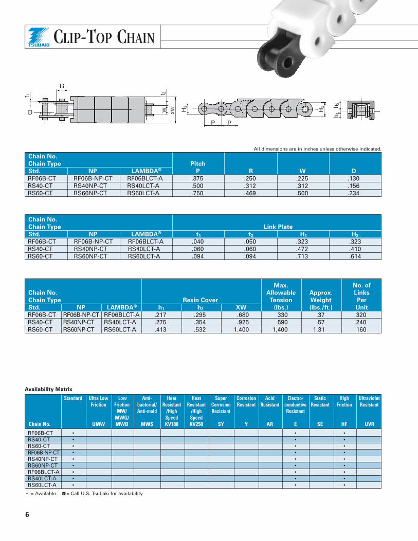
CLIP-TOP CHAIN
6
Max. No. of
Chain No. Allowable Approx. Links
Chain Type Resin Cover Tension Weight Per
Std. NP LAMBDA® h1 h2 XW (lbs.) (lbs./ft.) Unit
RF06B-CT RF06B-NP-CT RF06BLCT-A .217 .295 .680 330 .37 320 RS40-CT RS40NP-CT RS40LCT-A .275 .354 .925 590 .57 240 RS60-CT RS60NP-CT RS60LCT-A .413 .532 1.400 1,400 1.31 160
t 1 t 2W H
1
P P
H2
h 1h 2
All dimensions are in inches unless otherwise indicated.
Chain No.
Chain Type Pitch
Std. NP LAMBDA® P R W D
RF06B-CT RF06B-NP-CT RF06BLCT-A .375 .250 .225 .130 RS40-CT RS40NP-CT RS40LCT-A .500 .312 .312 .156 RS60-CT RS60NP-CT RS60LCT-A .750 .469 .500 .234
Chain No.
Chain Type Link Plate
Std. NP LAMBDA® t1 t2 H1 H2
RF06B-CT RF06B-NP-CT RF06BLCT-A .040 .050 .323 .323 RS40-CT RS40NP-CT RS40LCT-A .060 .060 .472 .410 RS60-CT RS60NP-CT RS60LCT-A .094 .094 .713 .614
Availability Matrix
Standard Ultra Low Low Anti- Heat Heat Super Corrosion Acid Electro- Static High UltravioletFriction Friction bacterial/ Resistant Resistant Corrosion Resistant Resistant conductive Resistant Friction Resistant
MW/ Anti-mold /High /High Resistant ResistantMWG/ Speed Speed
Chain No. UMW MWB MWS KV180 KV250 SY Y AR E SE HF UVR
RF06B-CT • • • RS40-CT • • • RS60-CT • • • RF06B-NP-CT • • • RS40NP-CT • • • RS60NP-CT • • • RF06BLCT-A • • • RS40LCT-A • • • RS60LCT-A • • •
• = Available ☎ = Call U.S. Tsubaki for availability
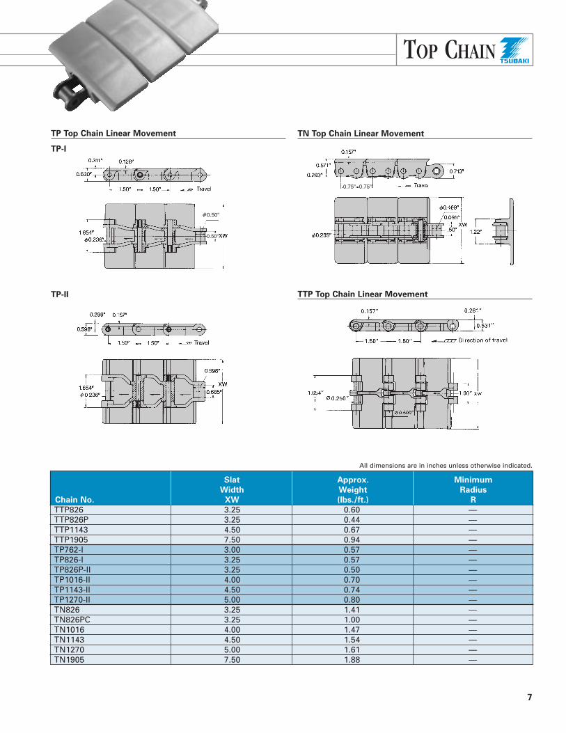
TOP CHAIN
7
TP Top Chain Linear Movement
TP-I
TP-II TTP Top Chain Linear Movement
TN Top Chain Linear Movement
Slat Approx. Minimum
Width Weight Radius
Chain No. XW (lbs./ft.) R
TTP826 3.25 0.60 — TTP826P 3.25 0.44 — TTP1143 4.50 0.67 — TTP1905 7.50 0.94 — TP762-I 3.00 0.57 — TP826-I 3.25 0.57 — TP826P-II 3.25 0.50 — TP1016-II 4.00 0.70 — TP1143-II 4.50 0.74 — TP1270-II 5.00 0.80 — TN826 3.25 1.41 — TN826PC 3.25 1.00 — TN1016 4.00 1.47 — TN1143 4.50 1.54 — TN1270 5.00 1.61 — TN1905 7.50 1.88 —
All dimensions are in inches unless otherwise indicated.

.598
.299
.157
.638
1.50 1.50 1.638
.685
.598
XW
R24"
TOP CHAIN
8
Slat Approx. Minimum
Width Weight Radius
Chain No. XW (lbs./ft.) R
TTUP826 3.25 0.67 24 TTUP826P 3.25 0.47 24 TTUP1143 4.50 0.74 24 TTUP1143P 4.50 0.54 24 TTUP1905 7.50 1.07 24 TPU826 3.25 0.67 20 TPU826P 3.25 0.54 20 TNU826 3.25 1.47 20 TNU1143 4.50 1.54 20 TNU1270 5.00 1.68 20
TTUP Top Chain Curved Movement
TNU Top Chain Curved Movement TPU Top Chain Curved Movement
All dimensions are in inches unless otherwise indicated.

Corrosion Resistance Guide
304 Ultra-highStainless Polymer
Fluid Steel Polyacetal Steel Polyethylene Acetic Acid (5%) X X F F Acetone X F F F Alcohol F F F F Aqueous Ammonia P F F F Beer F F F F Benzene F F F P Carbon Tetrachloride P F P P Caustic Soda (25%) X X F F Citric Acid X P F F Formic Acid X X X F Formic Acid Aldehyde F F F FFruit Juice X F F F Gasoline F F F P Hydrogen Peroxide X X F F Hypochlorite Soda X X X F Lactic Acid X F F F Milk F F F F Nitric Acid (5%) X X F P Oils (Vegetable & Mineral) F F F F Paraffin F F F F Phosphoric Acid X X P F Rice Vinegar (5%) X F P F Seawater X P P F Soapy Water P F F F Sodium Chloride X F P F Soft Drinks F F F F Vegetable Juice P F F F Water X F F F Whiskey F F F F Wine F F F F
F = Fully Resistant P = Partially Resistant X = Not Recommended The above Corrosion Resistance Guide should be used for reference only and does not state or imply any warranty conditions. The table shows results oflab tests at 68° F. Humidity and other conditions must also be considered when selecting Top Chain and liner materials.
TOP CHAIN
9
Availability Matrix
Standard Ultra Low Low Anti- Heat Heat Super Corrosion Acid Electro- Static High UltravioletFriction Friction bacterial/ Resistant Resistant Corrosion Resistant Resistant conductive Resistant Friction Resistant
MW/ Anti-mold /High /High Resistant ResistantMWG/ Speed Speed
Chain No. UMW MWB MWS KV180 KV250 SY Y AR E SE HF UVRTTP826 • • • • • • • • • • • • TTP826P • • • •TTP1143 • • • • • • • • • • • • TTP1905 • • • • • • • • • • • • TP762-I • • • • • • • TP826-I • • • • • • • TP826P-II • ☎ • • • • • • • TP1016-II • • • • • • • • • TP1143-II • • • • • • • • • TP1270-II • • • • • • • • • TN826 • • • • TN826PC • • •TN1016 • • • • TN1143 • • • • TN1270 • • • • TN1905 • • • • TTUP826 • • • • • • • • • • • TTUP826P • ☎ • • • • • • • TTUP1143 • • • • • • • • • • • TTUP1143P • ☎ • • • • • • • TTUP1905 • • • • • • • • • • • TPU826 • • • • • • • • • • • • TPU826P • ☎ • • • • • • • TNU826 • • • • TNU1143 • • • • TNU1270 • • • •
• = Available ☎ = Call U.S. Tsubaki for availability

Additional Information1. Offset links are not available. Please use an even number of links.
2. Existing RS standard sprockets can be used.
3. RF40PC to RF60PC use the same connecting links as stainless steelchain. RF25PC and RF35PC use special connecting links.
4. When replacing stainless steel chain with Poly-Steel Chain, check the chain tension. Chain tension should be less than the maximumallowable tension.
5. Ambient temperature range is -14˚F ~ 176˚F (-10˚C ~ 80˚C).
6. Maximum chain speed is less than 230 ft./min.
7. Coefficient of sliding friction between chain and guide rail is 0.25(without lubrication).
8. The guide rail should support the bottom side of the links.
9. The color of the inner links is brown.
Connecting and Disconnecting1. Disconnect as follows:
As shown in the drawing, place the pin link plate on the jig andpress down on the pin heads. Be careful not to apply too muchpressure to the plastic portion as breakage may occur.
2. For connecting, use a connecting link.
POLY-STEEL CHAIN
10
All dimensions are in inches unless otherwise indicated.
Pitch Pin
Chain No. P R W D L1 L2
RF25PC .250 .130 .125 .091 .177 .217
RF35PC .375 .200 .188 .141 .270 .309
RF40PC .500 .312 .312 .156 .325 .392
RF50PC .625 .400 .375 .200 .406 .472
RF60PC .750 .469 .500 .234 .506 .581
R
Max.
Allowable Approx.
Link Plate Load Weight
Chain No. T1 T2 H h (lbs.) (lbs./ft.) Color
RF25PC .030 .051 .236 .199 18 .06 Brown
RF35PC .050 .087 .354 .307 40 .15 Brown
RF40PC .060 .060 .472 .409 99 .26 Brown
RF50PC .080 .080 .591 .512 154 .39 Brown
RF60PC .094 .094 .713 .614 198 .55 Brown
Availability Matrix
Standard Ultra Low Low Anti- Heat Heat Super Corrosion Acid Electro- Static High UltravioletFriction Friction bacterial/ Resistant Resistant Corrosion Resistant Resistant conductive Resistant Friction Resistant
MW/ Anti-mold /High /High Resistant ResistantMWG/ Speed Speed
Chain No. UMW MWB MWS KV180 KV250 SY Y AR E SE HF UVR
RF25PC • • • • • RF35PC • • • • • RF40PC • • • • • • • • RF50PC • • • • • • • • RF60PC • • • • • • • •
• = Available ☎ = Call U.S. Tsubaki for availability

POLY-STEEL CHAIN
11
Corrosion Resistance Guide
Substance Concentration Temperature (°F) PC Chain PC-SY Chain Acetic Acid 10% 68 H H Alcohol H H Ammonia Water 68 H H Ammonium Nitrate Boiling P H Beer 68 H H Benzene 68 H H Butyric Acid 68 H X Calcium Chloride 68 P H Calcium Hydroxide 20% Boiling H H Calcium Hypochlorite 11-14% 68 X HCarbolic Acid X HCarbon Tetrachlorite (dry) 68 H H Chlorine Gas (dry) 68 X HChlorine Gas (moist) 68 X HChromic Acid 5% 68 X HCitric Acid 50% 68 X HCoffee Boiling H H Developing Solution 68 H H Ethyl Ether 68 H H Ferric Acid 50% 68 X HFormic Acid 50% 68 X HFruit Juice 68 H H Gasoline 68 H H Glycerol 68 H H Honey H H Hydrochloric Acid 2% 68 X HHydrogen Peroxide 30% 68 X HHydrogen Sulfide (dry) H H Ketchup 68 H H Lactic Acid 10% 68 H H Linseed Oil 68 H X Malic Acid 50% Boiling H H Mayonnaise 68 H H Milk 68 H H Nitric Acid 5% 68 X HNitric Acid 65% 68 X HOil (Plant, Mineral) 68 H H Oleic Acid 68 H X Oxalic Acid 10% 68 X HParaffin 68 H X Petroleum 68 H H Phosphoric Acid 5% 68 X HPhosphoric Acid 10% 68 X HPotassium Bichromate 10% 68 H X Potassium Hydroxide 20% 68 H H Potassium Nitrate 25% 68 H X Potassium Permanganate Saturation 68 X HSeawater 68 P H Soap-and-water Solution 68 H X Sodium Chloride 5% 68 H H Sodium Hydrocarbonate 68 H H Sodium Hydroxide 25% 68 H X Sodium Hypochlorite 10% 68 X HSoft Drinks 68 H H Sugar Solution 68 H H Sulfuric Acid 5% 68 X HSynthetic Detergent H H Syrup H H Tartaric Acid 10% 68 H H Vegetable Juice 68 H H Vinegar 68 P H Water H H Whiskey 68 H H Wine 68 H H Zinc Chloride 50% 68 P H Zinc Sulfate 25% 68 X H
H = Highly corrosion resistant P = Partially corrosion resistant X = Not Recommended

All dimensions are in inches unless otherwise indicated.
Pitch Pin Link Plate
Chain No. P R1 W d1 L1 H T
RT404SS .500 .313 .313 .154 5.339 .437 .059 RT408SS .500 .313 .313 .154 9.276 .437 .059 RT412SS .500 .313 .313 .154 13.213 .437 .059 RT416SS .500 .313 .313 .154 17.150 .437 .059 RT504SS .625 .400 .375 .200 5.622 .547 .079 RT508SS .625 .400 .375 .200 9.559 .547 .079 RT512SS .625 .400 .375 .200 13.496 .547 .079 RT516SS .625 .400 .375 .200 17.433 .547 .079 RT520SS .625 .400 .375 .200 21.370 .547 .079 RT524SS .625 .400 .375 .200 25.307 .547 .079 RT604SS .750 .469 .500 .235 6.047 .661 .094 RT608SS .750 .469 .500 .235 9.984 .661 .094 RT612SS .750 .469 .500 .235 13.921 .661 .094 RT616SS .750 .469 .500 .235 17.858 .661 .094 RT620SS .750 .469 .500 .235 21.795 .661 .094 RT624SS .750 .469 .500 .235 25.732 .661 .094
ROLLER TABLE CHAIN
12
(does not rotate)
R 1
Center
Distance Max.
Effective Between Allowable Approx.
Plastic Roller Width Chains Load Weight
Chain No. R2 L2 C1 C3 (lbs./ft.2) (lbs./ft.)
RT404SS .480 1.969 3.984 4.551 41 2.71 RT408SS .480 1.969 7.921 8.488 41 4.54 RT412SS .480 1.969 11.858 12.425 41 6.37 RT416SS .480 1.969 15.795 16.362 41 8.21 RT504SS .598 1.969 3.984 4.685 61 3.90 RT508SS .598 1.969 7.921 8.622 61 6.37 RT512SS .598 1.969 11.858 12.559 61 8.85 RT516SS .598 1.969 15.796 16.496 61 11.35 RT520SS .598 1.969 19.732 20.433 61 13.80 RT524SS .598 1.969 23.669 24.370 61 16.28 RT604SS .720 1.969 3.984 4.882 61 4.52 RT608SS .720 1.969 7.921 8.819 61 6.98 RT612SS .720 1.969 11.858 12.756 61 9.43 RT616SS .720 1.969 15.795 16.693 61 11.88 RT620SS .720 1.969 19.732 20.630 61 14.33 RT624SS .720 1.969 23.669 24.567 61 16.78
RT TYPE ROLLER TABLE CHAIN Both sides of chain: Stainless Steel
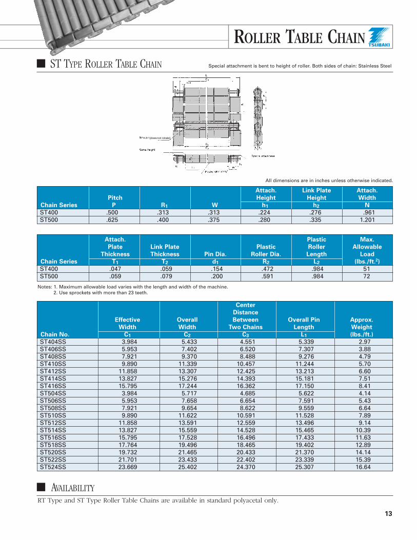
ROLLER TABLE CHAIN
13
(does not rotate)
All dimensions are in inches unless otherwise indicated.
Attach. Link Plate Attach.
Pitch Height Height Width
Chain Series P R1 W h1 h2 N
ST400 .500 .313 .313 .224 .276 .961 ST500 .625 .400 .375 .280 .335 1.201
Center
Distance
Effective Overall Between Overall Pin Approx.
Width Width Two Chains Length Weight
Chain No. C1 C2 C3 L1 (lbs./ft.)
ST404SS 3.984 5.433 4.551 5.339 2.97 ST406SS 5.953 7.402 6.520 7.307 3.88 ST408SS 7.921 9.370 8.488 9.276 4.79 ST410SS 9.890 11.339 10.457 11.244 5.70 ST412SS 11.858 13.307 12.425 13.213 6.60 ST414SS 13.827 15.276 14.393 15.181 7.51 ST416SS 15.795 17.244 16.362 17.150 8.41 ST504SS 3.984 5.717 4.685 5.622 4.14 ST506SS 5.953 7.658 6.654 7.591 5.43 ST508SS 7.921 9.654 8.622 9.559 6.64 ST510SS 9.890 11.622 10.591 11.528 7.89 ST512SS 11.858 13.591 12.559 13.496 9.14 ST514SS 13.827 15.559 14.528 15.465 10.39 ST516SS 15.795 17.528 16.496 17.433 11.63 ST518SS 17.764 19.496 18.465 19.402 12.89 ST520SS 19.732 21.465 20.433 21.370 14.14 ST522SS 21.701 23.433 22.402 23.339 15.39 ST524SS 23.669 25.402 24.370 25.307 16.64
Attach. Plastic Max.
Plate Link Plate Plastic Roller Allowable
Thickness Thickness Pin Dia. Roller Dia. Length Load
Chain Series T1 T2 d1 R2 L2 (lbs./ft.2)
ST400 .047 .059 .154 .472 .984 51 ST500 .059 .079 .200 .591 .984 72
RT Type and ST Type Roller Table Chains are available in standard polyacetal only.
AVAILABILITY
ST TYPE ROLLER TABLE CHAIN Special attachment is bent to height of roller. Both sides of chain: Stainless Steel
Notes: 1. Maximum allowable load varies with the length and width of the machine. 2. Use sprockets with more than 23 teeth.

14
CONFIRM THE OPERATING CONDITIONSOF THE CONVEYOR
1. Type of conveyor (slat conveyor, bucket elevator, etc.)
2. Method of chain travel (horizontal, inclined, or vertical)
3. Type, weight, and size of conveyed materials
4. Weight of conveyed materials per foot of conveyor length
5. Conveyor speed
6. Conveyor length
7. Method of lubrication
8. Considerations for special environments
SELECT THE APPROXIMATE CHAIN SIZEUse the following formula to estimate the chain tension(T). Select a chain with an allowable load equal to orabove the result.
T (lbs.) = MT • f • k1
MT = Total weight of conveyed material (lbs.)f = = Coefficient of friction, sliding and/or rolling
(f1 and/or f2 of Table I and II).k1 = Chain speed coefficient (Table III)
CALCULATE THE DESIGN CHAIN TENSIONCalculate the chain tension using the actual weight of theconveyor chain and material conveyed, as shown.
Chain Rolling
■ Horizontal Conveyor
T = (M + 2.1 w) f1 C
■ Horizontal Accumulating Conveyor
T = (W1 + M) L1 f1 + W2 L2 f2 + (W2 + M) L2 f3 + 1.1 M (L1 + L2) f1
■ Inclined Conveyor
T = (M + w) (f1 Ccos� + Csin�) + 1.1 w (f1 Ccos� - Csin�)
When (f1 Ccos� - Csin�) < 0, 1.1 w (f1 Ccos� - Csin�) = 0
orT = (M + w) (V + f1 H) + 1.1 w (f1 H – V)When (f1 H –V) < 0, 1.1 w (f1 H –V) = 0
■ Horizontal Plus Inclined Conveyor
T = (M + 2.1 w) f1 C1 + (M + w) (f1 C2cos� + C2sin�) + 1.1 w (f1 C2cos� - C2sin�)
When (f1 C2cos� - C2sin�) < 0, 1.1 w (f1 C2cos� - C2sin�) = 0
orT = (M + 2.1 w) f1 C1 + (M + w) (V + f1 H) + 1.1 w (f1 H – V)When (f1 H – V) < 0, 1.1 w (f1 H – V) = 0
■ Vertical Conveyor
T = (M + w) V
STEP 1
STEP 2
STEP 3
SELECTION GUIDELINES

15
Chain Sliding
■ Horizontal Conveyor
T = (M + 2.1 w ) f2 C
■ Horizontal Accumulating Conveyor
T = (M + w) L1 f2 + M2 L2 f2 + (M2 + w) L2 f3 + 1.1 w (L1 + L2) f2
■ Inclined Conveyor
T = (M + w) (f2 Ccos� + Csin�) + 1.1 w (f2 Ccos� - Csin�)When (f2 Ccos� - Csin�) < 0, 1.1 w (f2 Ccos� - Csin�) = 0
orT = (M + w) (V + f2 H) + 1.1 w (f2 H –V)When (f2 H – V) < 0, 1.1 w (f2 H – V) = 0
■ Horizontal Plus Inclined Conveyor
T = (M + 2.1 w) f2 C1 + (M + w) (f2 C2cos� + C2sin�) + 1.1 w (f2 C2cos� - C2sin�)
When (f2 C2cos� - C2sin�) < 0, 1.1 w (f2 C2cos� - C2sin�) = 0
orT = (M + 2.1 w) f2 C1 + (M + w) (V + f2 H) +
1.1 w (f2 H – V)When (f2 H – V) < 0, 1.1 w (f2 H – V) = 0
■ Top Chain Linear Movement
(Use this formula for TP, TN, TTP, RSP and Clip-Top Chain)
T = (M + 2.1 w) f2 C + M L2 f3
■ Curved Movement
(Use this formula for TPU and TNU Chain)Chain tension for curved movement is calculated similarlyto that for linear movement. The tension at corners iscompensated for by angle factor (K2) and length factor(K3).
Calculate chain tension for each part ABC…F. The tensionat F is the greatest acting on the chain.T = T F
Slack side:
Chain tension at A : T AT A = L1 w f2 k2, L1 = l1 + R1 k3 (k2 and k3 at 180°)Chain tension at B : T BT B = {T A + L2 w f2} k2, L2 = l2 + R2 k3 (k2 and k3 at 90°)Chain tension at C : T CT C = T B + L3 w f2, L3 = l3
Liner
SELECTION GUIDELINES

STEP 5
STEP 2
16
STEP 4Loaded side:
Chain tension at D : T DT D = {T C + (M + w) L4 f2 + M L'4 f3} k2,
L4 = l3 + R2 k3
(k2 and k3 at 90˚)Chain tension at E : T ET E = {T D + (M + w) L5 f2 + M L'5 f3} k2,
L5 = l2 + R1 k3
(k2 and k3 at 180˚)Chain tension at F : T FT F = T E + (M + w) L6 f2 + M L'6 f3
VERIFY THE CHAIN SELECTION
Multiply the chain tension (T) by the chain speed coefficient (K1) listed in Table V and verify the following formula.
T • K1 < Maximum allowable load of the chain
When the design chain tension (T • K1) is more than theallowable load or significantly less than it, retry the samesteps for the next larger or smaller chain size.
VERIFY THE ALLOWABLE ROLLER LOADWhen the load is carried on the rollers, the total weight ofthe chain and the load per roller should not exceed theallowable roller load shown in Table VI.
Table VI: Allowable Roller Load
Allowable Roller Load (lbs./roller)
AS and SS
Chain No. Stainless Roller Standard Roller
RS40 44 33 RS60 110 66 C2040 44 33
Table V: Chain Speed Coefficient (K1)
Chain Speed (ft./min.) Speed Factor (K1)
0 ~ 50 1.0 50 ~ 100 1.2
100 ~ 160 1.4 160 ~ 230 1.6 230 ~ 300 2.2 300 ~ 360 2.8 360 ~ 400 3.2
Table IV: Angle Factor and Length Factor (k2 and k3)
Angle Factor (k2)
TPU and TNU Chains
Turning Angle Length Factor (k3) Dry Lubricated
30° 0.5 1.15 1.10 60° 1.0 1.30 1.15 90° 1.6 1.50 1.25 120° 2.1 1.70 1.35 150° 2.6 1.90 1.50 180° 3.1 2.20 1.60
Table I: Coefficient of Rolling Friction (f1)
Type of Roller Dry Lubricated
Standard “S” roller type .21 .14
Table II: Coefficient of Sliding Friction (f2)
Dry Lubricated
Chain and rail .30 .20 Top plate and liner .25 .15
Table III: Coefficient of Friction between Material Conveyed
and Top Plate (f3)
Coefficient of
Conveyed Material Lubrication Dynamic Friction
Plastic and paper Dry 0.25containers and film packages
Soapy water 0.10
Metal cans Dry 0.25 Soapy water 0.15
Bottles and ceramics Dry 0.40
Soapy water 0.20
Metal industrial partsDry 0.25 Oil 0.15
SELECTION GUIDELINES

STEP 6
17
T = Chain tension (lbs.) w = Weight of chain and attachments (lbs./ft.) M = Weight of conveyed material (lbs./ft.)M2 = Weight of accumulating material (lbs./ft.)V = Vertical center distance of conveyor (ft.)H = Horizontal center distance of conveyor (ft.)C = Center distance between sprockets (ft.)L1 = Length of conveying section (ft.)L2 = Length of accumulating section (ft.)L´ = Length of accumulating section for curved
movement chain (ft.)l = Length of conveyor not loaded (ft.)f1 = Coefficient of rolling friction between chain and
guide railf2 = Coefficient of sliding frictionf3 = Coefficient of friction between material conveyed
and top plate� = Transmission efficiencyS = Speed = P N n/12 (ft./min.)P = Chain pitch (in.)N = Number of sprocket teethn = Sprocket speed (rpm)
CALCULATE THE REQUIRED POWER (HP)■ Horizontal and/or Inclined Conveyor
HP = T•S33,000 • �
■ Vertical Conveyor
HP = M•V•S33,000 • �
CONVEYOR DESIGNThe layout of a conveyor varies with the type of chainused. A typical layout is shown below. Goods should beconveyed on the tension side of the chain, and the slack(return) side should be supported by guide rails withsloped ends to prevent chain vibration and conveyor pulsation.
Guide rail selectionThe guide rail consists of the conveyor frame and liner.The top chain slides along the liner to minimize frictionalresistance and wear to protect the chain and minimize thedriving power.
Location of guide rails and sprocketWhen the chain engages with the sprocket, the chainmoves up and down slightly due to the sprocket’s polygonaleffect. Therefore, the guide rail on the loaded side mustbe positioned so that the chain is horizontal when at thehighest level. Use the following equation to determineguide rail installation dimension (A).
A = Pitch diameter of sprocket + B (in.)2
Chain Type B C
TN • TNU .433 1.496 TP-I .197 1.496 TP-II • TPU • TTP .157 1.496
Note: Refer to page 3 for RS Plastic Chain.
Dimensions are in inches
SELECTION GUIDELINES
A
C

18
Liner
FrameW
Frame
Linear Movement Chain
Conveying Side Return Side (Top Plate Sliding)
Liner
Frame
W1
W2
W1 Liner
W2
t1t3
W2Liner
t1
Liner
t1t2
Frame
Liner
Liner
Frame
t1
W3
Liner
Frame
t1t2
Liner
Curved Movement Chain
Straight Section Curved Section
TTUPTNU
Conveying Side
TPU
Conveying Side
Conveying Side Return Side
Return Side Return Side
Linear Movement Chain (in.)
Chain Type X W
RF06B-CT 0.780 0.750 RS40-CT 1.025 1.000 RS60-CT 1.500 1.500 TP — 1.772 TTP — 1.772 TN — 1.496
Curved Movement Chain (in.)
Chain
Type W1 W2 W3 W4 W5 t1 t2 t3
TPU 1.772 1.772 1.772 1.890 1.890 .472 .472 .472 TNU 1.496 1.496 1.496 — — .709 .709 —
■ Guide rail inside width
SELECTION GUIDELINES
“A” = Sprocket Pitch Diameter - Roller Diameter2
Dimension “A” appliesto Clip-Top Chain only.

19
1. Allow 3.5 to 5.5 inches of slack under the drive sprocketduring operation.
2. An engagement angle of more than 150° must bebetween the drive sprocket and the chain.
3. The guide rail radius R (in.) must be larger than theradius of chain backbend listed in the table below.
4. Guide rails must have sloped ends to prevent interference with the chain.
SELECTION PROCEDURE FORROLLER TABLE CHAIN
Use the following capability graphs to determine RollerTable size;
■ ST Roller Table Conveyor Capability Graph
How to use the graph:If W equals 61 lbs./ft.2 and the conveyor length equals32.8 ft., select Roller Table numbers ST514 to ST504.W = Weight of conveyed load (lbs./ft.2)
= Weight of conveyed object (lbs.)
Base area of conveyed object (ft.2)
■ Slack side guide rail arrangement
Top plate sliding (applicable for all Top Chains)
Attachment sliding (TPU type)
Chain Type h H
TPU .236 1.024
Minimum Radius of Chain Backbend (in.)
Chain Type Min. Backbend Radius
RS40P 5 RS60P 18 RS2040P 18 RF06B-CT 12RS40-CT 8.25RS60-CT 14TP•TTP•TPU 2 TN•TNU 4
SELECTION GUIDELINES
20
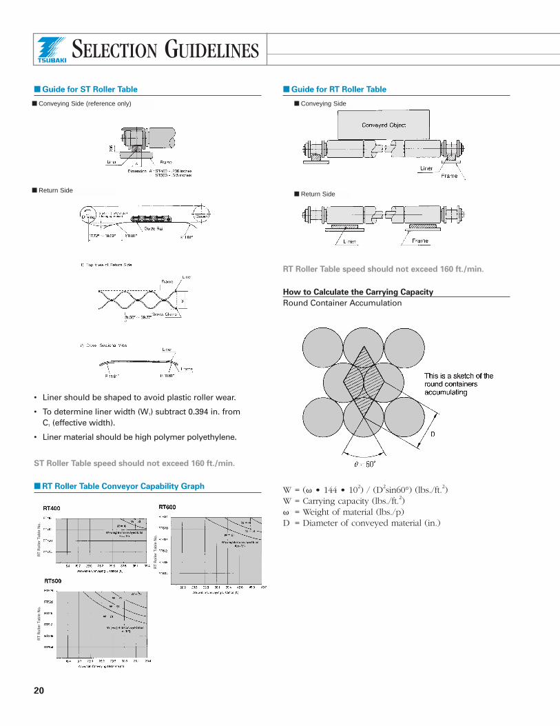
■ Guide for ST Roller Table
• Liner should be shaped to avoid plastic roller wear.
• To determine liner width (W1) subtract 0.394 in. from C1 (effective width).
• Liner material should be high polymer polyethylene.
ST Roller Table speed should not exceed 160 ft./min.
■ RT Roller Table Conveyor Capability Graph
■ Guide for RT Roller Table
RT Roller Table speed should not exceed 160 ft./min.
How to Calculate the Carrying Capacity
Round Container Accumulation
W = (� • 144 • 102) / (D2sin60°) (lbs./ft.2)W = Carrying capacity (lbs./ft.2)� = Weight of material (lbs./p)D = Diameter of conveyed material (in.)
RT
Ro
ller
Tab
le N
o.
RT
Ro
ller
Tab
le N
o.
RT
Ro
ller
Tab
le N
o.
■ Return Side
■ Conveying Side
■ Return Side
■ Conveying Side (reference only)
SELECTION GUIDELINES

21
Selection Procedure Example
Specifications
Conveyor length: 26.2 ft.Weight of conveyed object: 44 lbs.Dimensions of conveyed object:
0.98 ft. • 0.66 ft. • 0.33 ft.
Selection
Select ST type for smooth conveying and to provide “side-through” transfer lines.
From the ST Roller Table Capability Graph:W = 44/(0.98 • 0.66) = 68 lbs./ft.2
According to the following table, if W = 68 lbs./ft.2
and the conveyor length is 26.2 ft., ST504~ST516 is the appropriate selection.
Determine the chain width (C1) using the dimension diagrams on pages 12 and 13.
In this example, ST510SS Roller Table Chain with width(C1) of 9.890 in. was selected for objects with the abovedimensions.
GENERAL ENGINEERING INFORMATION
Points to consider:
1. Use take-up devices to eliminate chain slack on longconveyors. Take-up stroke = (Center distance between sprocket • 0.02) + Catenary sag allowance.
2. Always engage chain with at least three sprocket teeth.
3. All sprocket teeth on the head shaft should be alignedwhen two or more strands of conveyor chain are inoperation. Chain may be matched at the factory for uniform length and accurate multiple-strand operation.
Considerations for use in special environments:
1. Under very low or high temperatures:Special consideration must be taken when chain is tooperate in freezing chambers, cold areas, when it passesthrough a heat-treatment furnace, or when it will beaffected by heat from conveyed material.
2. In wet conditions:When chain is exposed to water, as in a sterilizer or water screen, excessive wear due to insufficientlubrication and rust may shorten chain life.
3. In corrosive conditions:When chain is exposed to an acidic or alkaline solutionor operated in a corrosive atmosphere, chemical corrosionmay cause excessive wear. Hydrogen embrittlement mayalso occur in an acidic environment. Exposure to sea ormine water may cause electrochemical corrosion.
Method of Chain Travel and Type of Rollers
Method of
Chain Travel Type of Roller Features
• Suitable for impactand harshconditions
• Economical• Impact
resistant• Greater
powerrequired
Standard “S” roller type• Lightweight• Lower allowable
roller load
Chain Rolling
Chain Sliding
(Double Pitch
Chain)
Generally used for:• Conveyor
lengths lessthan 35 ft.
• Conveyorspeeds lessthan 70 ft./min.
SELECTION GUIDELINES

22
4. In dusty conditions:Chain wears quickly in dusty conditions, such as in the presence of coke, metal powder, and sand, becauseforeign material gets between chain parts and in theengaging surfaces of the chain and sprocket teeth.
This information is intended to provide general guidelinesfor conveyor chain selection. Consult U.S. Tsubaki forspecific application problems.
Chain Type Feature Application
TPTTP TTP-P TN TN-NP TN-NP-LAMBDA TN-SS
RS-P
TTUP TTUP-P TPU TNU TNU-NP TNU-AS
Self-lubrication, quiet operation. Anti-corrosive, suitable for transportationof small-sized goods due to clearance between top plates.
Self-lubrication, quiet operation. Anti-corrosive, suitable for transportationof small-sized goods due to clearance between top plates.
Used for simple curved operation. TN type side bow feature.
Damage-free, quiet operation. Smooth transportation, easy removal oftop plate. Easy repair.
Quiet and trouble-free operation with anti-corrosive protection.
Conveying steel, cans, finished parts, paper-packages, etc.
Conveying electronic partsand small items.
Curved operation for TTUP.
Curved operation for TP.
Curved operation for TN.
LIN
EA
R M
OV
EM
EN
T
CU
RV
ED
MO
VE
ME
NT
Top Plate Selection and Engineering Information
Maximum Maximum
Speed Ambient Allowable
Materials (ft./min.) Temperature Load
Chain Type Top Plate Chain/Pin Lubricated Dry (°F) (lbs.)
TP Plastic 304
330 160 -4~176 264 Stainless Steel
TTP Plastic 304
330 160 -4~176 187 Stainless SteelTTP-P Plastic Plastic 330 160 -4~176 187 TN Plastic Carbon Steel 390 200 15~176 1,628
TN-NP Plastic Nickel-plated
390 200 15~176 1,628 Carbon Steel
TN-NP-LAMBDA PlasticNickel-plated
390 200 15~176 1,628 Carbon Steel
TN-SS Plastic 304
230 150 -4~176 231 Stainless Steel
RS-P Plastic 304
200 200 -4~176 Refer to page 3. Stainless Steel
TTUP Plastic 304
330 160 -4~176 240Stainless SteelTTUP-P Plastic Plastic 330 160 -4~176 195
TPU Plastic 304
260 160 -4~176 220 Stainless SteelTNU Plastic Carbon Steel 330 200 15~176 902
TNU-NP Plastic Nickel-plated
330 200 15~176 902 Carbon Steel
TNU-AS Plastic 600
330 150 -4~176 180Stainless Steel
LIN
EA
R M
OV
EM
EN
T
CU
RV
ED
MO
VE
ME
NT
SELECTION GUIDELINES

■ Top Plate Material Application
Select top plate material according to the type of goods to be moved.
■ Select the appropriate liner material.
23
Abrasive Atmosphere
Dry Lubricated
Conveyed Material Top Plate Material No Yes No Yes
Tin cans, aluminum cans, metal containers ★ ✕ ★Plastics and plastic-covered containers, Polyacetal ✕paper containersGlass jars, glass products, ceramics ✕ ✕
Abrasive Atmosphere
Dry Lubricated
Top Plate Material Liner Material No Yes No Yes
Polyacetal
Stainless Steel ★ ★
Steel ★ ★
Ultra-high Polymer ✕
Polyethylene
■ Establish general conveyor conditions.
A) Materials conveyed1) Container material2) Weight3) Dimensions
B) Conveyor arrangement1) Linear or curved movement2) Conveyor length3) Layout4) Space limitations
C) Other conditions1) Conveyor capacity2) Interval3) Conveyor speed4) Lubrication requirements5) Material conveyance regularity
D) Environment1) Temperature2) Corrosive conditions (See page 9)3) Wear-causing agents
Top Plate Selection
SELECTION GUIDELINES
★ Suggested Good Limited use ✕ Not suggested
★ Suggested Good Limited use ✕ Not suggested

U.S. Tsubaki, Inc.Corporate Headquarters301 E. Marquardt DriveWheeling, IL 60090Tel: (800) 323-7790
(847) 459-9500Fax:(847) 459-9515Web Site: www.ustsubaki.com
© U.S. Tsubaki, Inc. 2003 All Rights Reserved. Printed in the U.S.A. 4/03 L10914
NOTE: In accordance with the policy of U.S. Tsubaki, Inc., to consistentlyimprove its products, the specifications in this brochure are subject tochange without notice. FOR CURRENT TERMS AND CONDITIONS OFSALE, SEE OUR CURRENT PRICE LIST.