roll-designed 3d nanofibrous scaffold suitable for the ... research roll-designed 3d nanofibrous...
TRANSCRIPT

ORIGINAL RESEARCH
Roll-designed 3D nanofibrous scaffold suitablefor the regeneration of load bearing bone defects
Fatemeh Hejazi1 • Hamid Mirzadeh1
Received: 30 May 2016 / Accepted: 7 November 2016 / Published online: 18 November 2016
� The Author(s) 2016. This article is published with open access at Springerlink.com
Abstract In this work, an innovative and easy method for
the fabrication of 3D scaffold from 2D electrospun struc-
tures is introduced. For this aim, coral microparticles were
fixed inside the nanofibrous PCL/Gelatin mat and the
obtained structure was post assembled into a cylindrical
design. Scaffold fabrication procedure is described in detail
and morphological properties, physical and mechanical
characteristics and in vitro assessments of the prepared
scaffold are reported. Presences of coral microparticles in
the structure led to the formation of empty spaces (3D
pores) between nanofibrous layers which in turn prevent
the compact accumulation of nanofibers. Post-assembly of
the obtained nanofibrous coral-loaded structures makes it
possible to prepare a scaffold with any desired dimension
(diameter and height). Existence of coral particles within
the nanofibrous mats resulted in distant placement of layers
toward each other in the assembling step, which in turn
create vacancy in the structure for cellular migration and
fluid and nutrients exchange of the scaffold with the sur-
rounding environment. Cell morphology within the scaf-
folds is investigated and cytotoxicity and cytocompatibility
of the structure is evaluated using Alamar blue assay.
Enhancement in mineralization of the seeded cells within
the prepared coral-loaded scaffolds is demonstrated by the
use of SEM-EDX. Performed compression mechanical test
revealed excellent modulus and stiffness values for the
cylindrical samples which are comparable to those of nat-
ural bone tissue.
Keywords 3D scaffold � Coral microparticles � Cellularinteractions � Mechanical properties
Introduction
To the regeneration of a damaged tissue, in particular bone
tissue, the key factor is to develop a three dimensional
scaffold which mimics the microstructure, chemical com-
position and mechanical and functional properties of native
tissue. In this work, we aimed to develop a scaffold for the
regeneration of load bearing bone tissue.
Cortical bone, synonymous with compact bone, is one of
the two types of osseous tissue that form bones. Cortical
bone facilitates bone’s main functions: to support the
whole body, protect organs, provide levers for movement,
and store and release chemical elements, mainly calcium.
As its name implies, cortical bone forms the cortex, or
outer shell, of most bones. Compact bone is much denser
than cancellous bone, which is the other type of osseous
tissue. Furthermore, it is harder, stronger and stiffer than
cancellous bone. Cortical bone contributes about 80% of
the weight of a human skeleton. The primary anatomical
and functional unit of cortical bone is the osteon (Netter
1987). The osteon consists of a central canal called the
osteonic (haversian) canal, which is surrounded by con-
centric rings (lamellae) of matrix which are composed of
collagen nanofibers. Between the rings of matrix, the bone
cells (osteocytes) are located in spaces called lacunae.
Small channels (canaliculi) radiate from the lacunae to the
osteonic (haversian) canal to provide passageways through
the hard matrix. In compact bone, the haversian systems
are packed tightly together to form what appears to be a
solid mass (Cancer Registration and Surveillance Modules
2000; Martini et al. 2011; Ch 2012).
& Hamid Mirzadeh
1 Department of Polymer Engineering and Color Technology,
Amirkabir University of Technology (Tehran Polytechnic),
424 Hafez Avenue, 1591634311 Tehran, Iran
123
Prog Biomater (2016) 5:199–211
DOI 10.1007/s40204-016-0058-2
In tissue engineering, full differentiation and normal
biological activity of the cells requires the possibility of
their growth in a three dimensional manner (Kazemnejad
2009; Li et al. 2003). As such, providing 3D scaffold with
efficient porosity and pore size for freely and optimal cell
migration is essential (Thorvaldsson et al. 2008).
Electrospinning is one of the beneficial techniques for
the fabrication of assemblies with nanofibrous structure of
native ECM. Flexibility of process, variety of the possible
materials to be used, control over the morphology of the
obtained nanofibers and probability of additive incorpora-
tion within the nanofibrous structure are among the
advantageous of this method (Chomachayi et al. 2016).
However, small diameter of electrospun nanofibers
results in low porosity and small sized pores of the
obtained structure. In such condition, no cellular migration
can occur into the inner layers (Khorshidi et al. 2015),
which leads to 2D flattening of the growing cells on top of
the exterior surface.
To overcome these limitation of electrospun structures
many studies have been done such as; using the mixed
structure of nano and microfibers (Thorvaldsson et al.
2008; Khorshidi et al. 2015; Pham et al. 2006), applying
sacrificial agent between nanofibers (Kidoaki et al. 2005;
Nam et al. 2007),stacking electrospun layers and mem-
brane (Beachley et al. 2014; Madurantakam et al. 2013;
Tong and Wang 2013), assembly of spinned nanofibers
(Koh et al. 2010; Kim and Lee 2011), mechanical expan-
sion of the electrospun mats (Shim et al. 2010),rolling or
folding the fibers (Ru et al. 2013; Leung et al. 2012),
changing the solution properties (Hejazi and Mirzadeh
2016), and using liquid flow in the spinning fiber path
(Nguyen et al. 2012). Although these methods were more
or less successful in the modification of electrospinning
process, they raise other drawbacks for the obtained
structure such as decrease in mechanical properties.
In this work, we introduced an easy method for the
fabrication of 3D scaffold from electrospun structure which
possesses modified porosity and enhanced pore size in
addition to proper mechanical properties for load bearing
applications. For this aim, coral microparticles were fixed
within nanofibrous structure and the fabricated mat was
rolled up into the cylindrical shape.
Natural coral is comprised of calcium carbonate (more
than 98%) with highly porous structure possessing
numerous interconnected channels (http://www.drugs.com/
npp/coral.html). Due to its similarity to bone tissue, coral is
compatible and has a good degradation rate that could well
match the new bone formation rate in the application of
bone tissue engineering (Xiao et al. 2010). Natural coral
has good mechanical properties which are comparable to
that of native bone tissue (John and Chamberlain 1978).
This work is the first report of using a mixed structure of
polymer and natural coral. In fact, we have established this
innovative method to make use of biopolymers advanta-
geous in addition to natural coral benefits. Nanofibrous
micro structure and advanced cellular interactions of
polymer phase together with mechanical and osteconduc-
tive properties of coral, could help to achieve a proper
scaffold for the regeneration of load bearing bone defects.
Experimental
Materials
Polycaprolactone (PCL), MW = 80,000 Da and gelatin
from porcine skin, Type A, lyophilized powder, c-irradi-ated, BioXtra, suitable for cell culture, were purchased
from Sigma Aldrich. Acetic acid and ethyl acetate were
purchased from Merck (Germany). Coral was obtained
from Persian Gulf coral reefs.
Coral sizing and disinfection
Coral pieces were grinded by the use of mechanical mill
and the obtained particles were classified into different
sizes by the use of sequential sieves.
After being sorted, the coral microparticles were disin-
fected by immersing in sodium hypochlorite solution
(Merck, Germany) for 30 h followed by washing with
distilled water several times and vacuum drying. It is worth
to mention that the disinfection process of the coral was
carried out after they were grinded into micro sized parti-
cles, to enhance the exposure of their surface with disin-
fecting solution. After being disinfected, coral particles
were sterilized by being exposure to gamma radiation
(25 KG) for 2 h.
Scaffold fabrication method
16 wt% polymer solution for electrospinning was prepared
by dissolving PCL and gelatin with a weight ratio of 70:30
in a solvent mixture containing acetic acid, ethyl acetate,
and water in 3:2:1 ratio. 4.8% concentrations of gelatin was
taken in a glass container containing solvent and dissolved
at 50 �C under constant stirring for 4 h. After the gelatin
was dissolved, PCL (11.2 wt%) was added to this solution
and was stirred overnight at room temperature. (Binulala
et al. 2014).
The prepared polymer solutions were taken in a 5 ml
syringe and loaded in the electrospinning setup. Electro-
spinning was performed with an applied voltage of 10 kV,
flow rate of 1 ml/h and the needle tip and collector distance
200 Prog Biomater (2016) 5:199–211
123

(air gap) of 10 cm, to a grounded metallic rotating mandrel
for 1 h.
For the preparation of coral containing structures, ulti-
mate weight ratio of polymer to coral in the structure was
considered as 1:1 or 1:2. At desired time intervals (one
time after 30 min of electrospinning for obtaining 1:1 ratio,
and two times every 20 min for 1:2 ratio) a defined amount
of coral microparticles was loaded on the collected
nanofibrous mat (Fig. 1).
To obtain uniform distribution of coral microparticles,
first the particles were dispersed on a flat surface according
to a mesh pattern (Fig. 1). For this aim, a flat rectangular
plate which its width and length were equal to the length
(L) and circumference (pD) of the rotational mandrel,
respectively, was used as the substrate. For primary dis-
tribution of coral microparticles on this plate, a mesh (No
140, 70 and 50, for distribution of microparticles with the
size of 100, 200 and 300 lm, respectively) was put on it. A
Fig. 1 Schem of the step by
step procedure used for the
fabrication of coral-loaded roll
scaffolds
Prog Biomater (2016) 5:199–211 201
123

defined amount of coral (equal to the overall weight of the
nanofibrous layer that would form after 1 h of electro-
spinning) was dispersed on the plate which was covered
with mesh. After picking up the mesh from the plate, a
uniform distribution of particles was obtained according to
the pattern of the mesh pores.
At each considered time interval, the formed nanofi-
brous layer was wetted by spraying ethanol (70%) solution.
The collector mandrel which was covered by the wet
nanofibrous mat was removed from the electrospinning
chamber and put on the explained plate and rolled on it
from one side to the other. By this method, coral
microparticles were attached to the wet surface of nanofi-
brous mat with a uniform pattern. The mandrel which was
covered with coral-loaded nanofibrous mat was returned to
the electrospinning chamber and exposed to the further
spinning procedure.
To prepare the 3D scaffolds, the fabricated electrospun
mats (with or without coral microparticles) were cut into
strands with desired width and length, then these strands
were rolled up into cylindrical shape. To prevent the pre-
pared structure from unrolling, the ultimate (outer) layer
was attached to the former layer by a mild and quick
exposure of a small spot in the tail-end of outer layer of the
rolled structure to a hot surface. Seven types of roll scaf-
folds were prepared by varying the polymer to coral ratio
and coral particle size (Table 1).
Scaffold morphology
The morphological evaluation of the scaffolds was per-
formed with SEM (AIS 2100, Seron Technology, Korea)
after sputter coating (BAL TECH) with gold.
Porosity measurement
To measure the porosity of the prepared scaffolds, two
methods were considered.
Gravimetry method
In the first step, porosity of the prepared samples was
obtained from gravimetry method by the following equa-
tion (Szentivanyi et al. 2011):
Porosity %ð Þ ¼ 1� qsqmix
� 100 ¼ 1�Ws=Vs
qmix
� 100 ð1Þ
where WS represents the scaffold dry weight, Vs is the
volume of the scaffold and qmix stands for the density of
the used materials which determines with the following
equation (Feinstein 1972):
qmix ¼MT
VA þ VBð Þ ð2Þ
where MA and MB are mass of A and B in the mixture,
VA = MA
qA, and VB = MB
qB.
Mercury intrusion method
Mercury intrusion porosimetry was the second method
which was considered to determine scaffold porosity and
pore size.
In this method, mercury, which was a nonwetting liquid,
entered through the dry scaffold under pressurized condi-
tions. Samples placed in penetrometer and subjected to
high vacuum. By achieving the minimum required pressure
inside the penetrometer, mercury flowed and surrounded
the sample. Subtracting the initial volume of the mercury
which surrounds the sample from the volume of the pen-
etrometer gave the sample volume (Vscaffold). By increasing
the applied pressure, the mercury entered increasingly
smaller pores. Total volume of mercury forced into the
sample was defined as Vintrusion. As such, the open porosity
of the scaffold (p), which is accessible for the intrusion of
mercury, was calculated from the following equation
(Karageorgiou and Kaplan 2005; Loh and Choong 2013):
p ¼ Vintrusion
Vscaffold
� �� 100 ð3Þ
And the closed porosity (x), pores with no intery in
which the mercury can not diffuse through them, was
calculated by the use of total porosity (P) which was
determined by gravimetry method.
x ¼ P� p ð4Þ
The volume of the diffused mercury at each pressure
interval was used for the estimation of pore size. The pore
size was estimated using the Washburn equation:
r ¼ 2scos hð Þp
ð5Þ
Table 1 Prepared samples codes and composition
Sample code Polymer to coral ratio Coral microparticle size (lm)
CF-Roll 1:0 No loaded coral
Roll A 1:1 100
Roll B 1:1 200
Roll C 1:1 300
Roll D 1:2 100
Roll E 1:2 200
Roll E 1:2 300
202 Prog Biomater (2016) 5:199–211
123
where r is the pore radius, s is the surface tension of
mercury, h is the contact angle of the mercury, and p is
each pressure interval. Radius values were calculated
automatically and average value was obtained after all
points were recorded.
For all kind of samples, 3 individual replicants were
used and the results reported as the average value.
Water uptake test
The water uptake capacity of the prepared scaffolds was
determined by soaking them (n = 3) in phosphate buffered
saline (pH 7.4) at 37 �C for for 0.5, 1, 6, 24, 96 and 240 h.
The water-uptake ratio is defined as the ratio of the weight
increase to the initial weight (wd) (Pezeshki-Modaress et al.
2014).
W ¼ ½ðww � wdÞ=wd� � 100 ð6Þ
where ww represents the weight of the scaffolds after
immersion in the PBS solution at each time point and wd is
the initial weight of the dry scaffolds. For all kind of
samples, 3 individual replicants were considered and val-
ues are expressed as the mean ± standard deviation.
Mechanical analysis
Uniaxial mechanical tests were performed with (SANTAM,
STM-20) in z-directional (along with the cylinder axis) com-
pression mode, at a crosshead rate of 0.5 mm/min, and 0.05 N
preload. 3D samples (n = 3, Ø = 5 mm, h = 10 mm) were
tested in dry condition and compressive loadwas applied up to
50% deformation. Compressive modulus and stiffness were
drawn from the stress–strain curve elaboration. Data are
reported as average ± standard deviation.
MG63 cell preparation
In this study, MG-63 Human osteosarcoma cell line was
used for in vitro assays. MG-63 cells were cultured in
DMEM/F12 medium containing 10% FBS, 1% L-glu-
tamine, and 1% penicillin/streptomycin in T-75 tissue
culture flask, and the culture medium was refreshed every
3 days. Cells between three and four passages were used
for the experiments. Prior to each cell seeding, dissociated
cells (with 0.05% trypsin/EDTA) were centrifuged, and
then resuspended in fresh medium.
In vitro cytotoxisity evaluation
The possible release of low molecular weight cytotoxic
substances from the samples and also coral microparticles
were investigated by indirect cytotoxicity tests, using
MG63 human osteosarcoma cells line. Cylindrical samples
and coral microparticles (after being disinfected) were
sterilized by exposure to Gama irradiant for 120 min. To
obtain the extracts, three specimens from each considered
sample were immersed in DMEM medium supplemented
with 10% fetal bovine serum (FBS) and 1% penicillin/
streptomycin. Non-interfered complete medium was con-
sidered to prepare the control. 24 h before adding the
extract, MG63 cells were seeded (cell density = 2 9 104
cells/well) in a 96-well tissue culture plate. After 1, 4 and
7 days of incubation, the extracts and non-interfered
mediums were removed and replaced the medium of pre-
seeded cells. Three replicates for each eluate and medium
were considered. After 24 h, the culture medium of each
well was replaced with 150 ll Alamar BlueTM solution
(10% v/v in culture medium) and the plate incubated for
4 h. 100 ll from the solution of each well was transferred
to a 96 well plate and the absorbance measured using
Thermo Scientific Multiscan Spectrum plate reader (test
wavelength: 540 nm; reference wavelength: 630 nm).
Reported percentage is relative ratio of values related to the
cells in contact with samples to the cells in contact with
non-interfered medium.
Cell seeding
MG-63 cells were resuspended in growth medium con-
taining 10% FBS at the density of 7 9 105 (cells/ml). To
enhance cell attachment to the samples, 100 ll of cell
suspension was put directly onto the top of each scaffold to
obtain a total number of 7 9 104 cells/scaffold and the
samples were put in incubator. After 1.5 h each well was
filled up with the medium. The growth medium was
replaced regularly every 2 days.
Cell morphological observation
At considered time points for morphological investigation
(4 h, 1, 3, 5, and 7 days), cell cultured samples were
detached, washed with PBS solution and fixed in 4% glu-
taraldehyde solution for 30 min. After cell fixation, sam-
ples were washed with PBS buffer again to remove residual
glutaraldehyde followed by dehydration in sequentially
increasing ethanol solutions (10 min for each concentra-
tion). Specimens were subsequently dried in vacuum
overnight. Prepared samples were gold sputtered and
observed under scanning electron microscope (AIS 2100,
Seron Technology, Korea).
Histological evaluation
After In Vitro cell culture, at desired time points, the scaf-
folds were fixed with a formalin10% solution and
Prog Biomater (2016) 5:199–211 203
123
embedded in paraffin. Paraffin blocks were sectioned (5 lmthick), placed onto charged glass slides, deparaffinized and
rehydrated. For histological analysis, sections were stained
with hematoxylin and eosin (H&E) to visualize cell infil-
tration and distribution using optical microscope.
Cell proliferation
To evaluate the MG-63 cells proliferation within the pre-
pared scaffolds, direct cytocompatibility test was per-
formed in considered time points. For this aim, cylindrical
samples (D = 15 mm, h = 5 mm) were cell seeded (with
the density of 7 9 104 (cells/well)) in 24-multiwell tissue
culture plate up to 21 days. At each time point, cells via-
bility (which is a sign of cell number at each time interval)
was determined by replacing culture medium with 2 ml
AlamarBlueTM solution (10% v/v in culture medium).
After 4 h, solution from each well was transferred to 3
wells of 96-multi well plate (100 ll in each well) and
fluorescence value was measured at (test wavelength:
540 nm; reference wavelength: 630 nm). Average value
related to each sample, was normalized by dividing to the
average fluorescence value of the controls. Subsequently,
scaffolds were washed with PBS, fresh culture medium
was added and the plate was transferred to the incubator for
the next time-point.
MG-63 cell mineralization
Calcium formation on the MG-63 cell seeded scaffolds,
was identified by SEM instrument (VEGA, TESCAN,
Czech) equipped with energy dispersive X-ray (EDX)
spectrometer.
Statistical analysis
Statistical analysis was performed using One Way
ANOVA analysis of variance (SPSS 16.0 software) fol-
lowed by Tukey’s significant difference post hoc test.
Experiments were performed in triplicate and data are
expressed as mean ± standard deviation. A p value\0.05
was considered statistically significant.
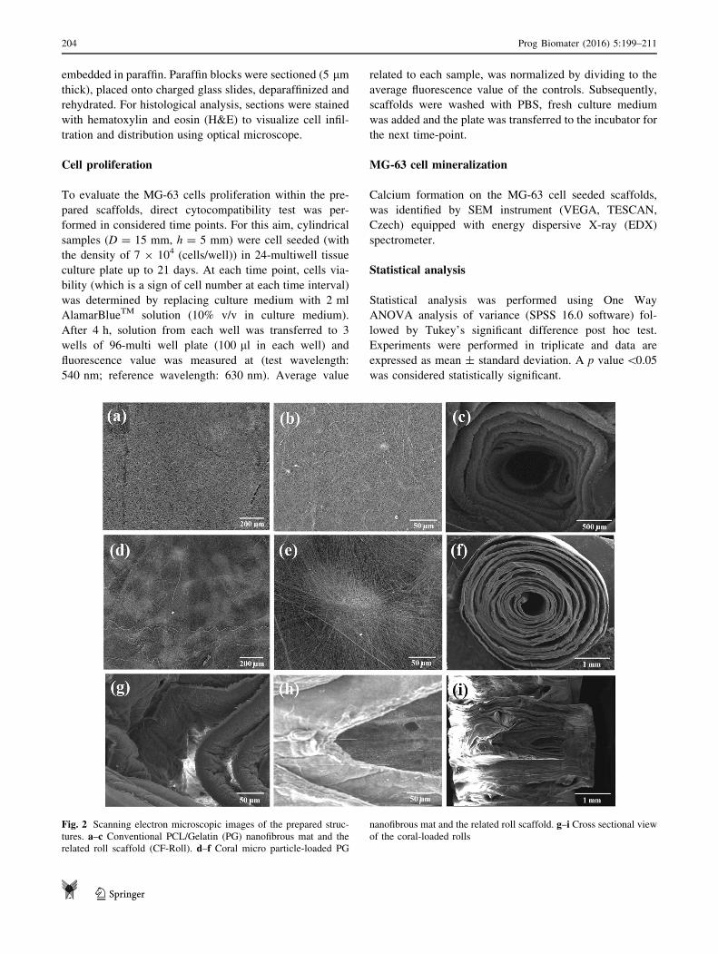
Fig. 2 Scanning electron microscopic images of the prepared struc-
tures. a–c Conventional PCL/Gelatin (PG) nanofibrous mat and the
related roll scaffold (CF-Roll). d–f Coral micro particle-loaded PG
nanofibrous mat and the related roll scaffold. g–i Cross sectional viewof the coral-loaded rolls
204 Prog Biomater (2016) 5:199–211
123
Results and discussion
Morphological evaluation of the scaffold
Figure 2 shows the SEM micrographs of the prepared
structures. The compact accumulation of nanofibers in 2D
electrospun mat is illustrated in upper lane, while existence
of coral microparticles between the spun nanofibers formed
a porous structure with non-compact nanofibrous layers
(second lane). Top views of the rolled coral-free and coral-
loaded nanofibrous layers are shown in Fig. 2c, f, respec-
tively. Horizontal and vertical cross sections of the rolled
scaffolds are shown in Fig. 2g, h in addition to focus on
inner region of vertical cross section (i). These cross-sec-
tional images illustrate the distant placement of nanofi-
brous layers as the result of the presence of coral
microparticles.
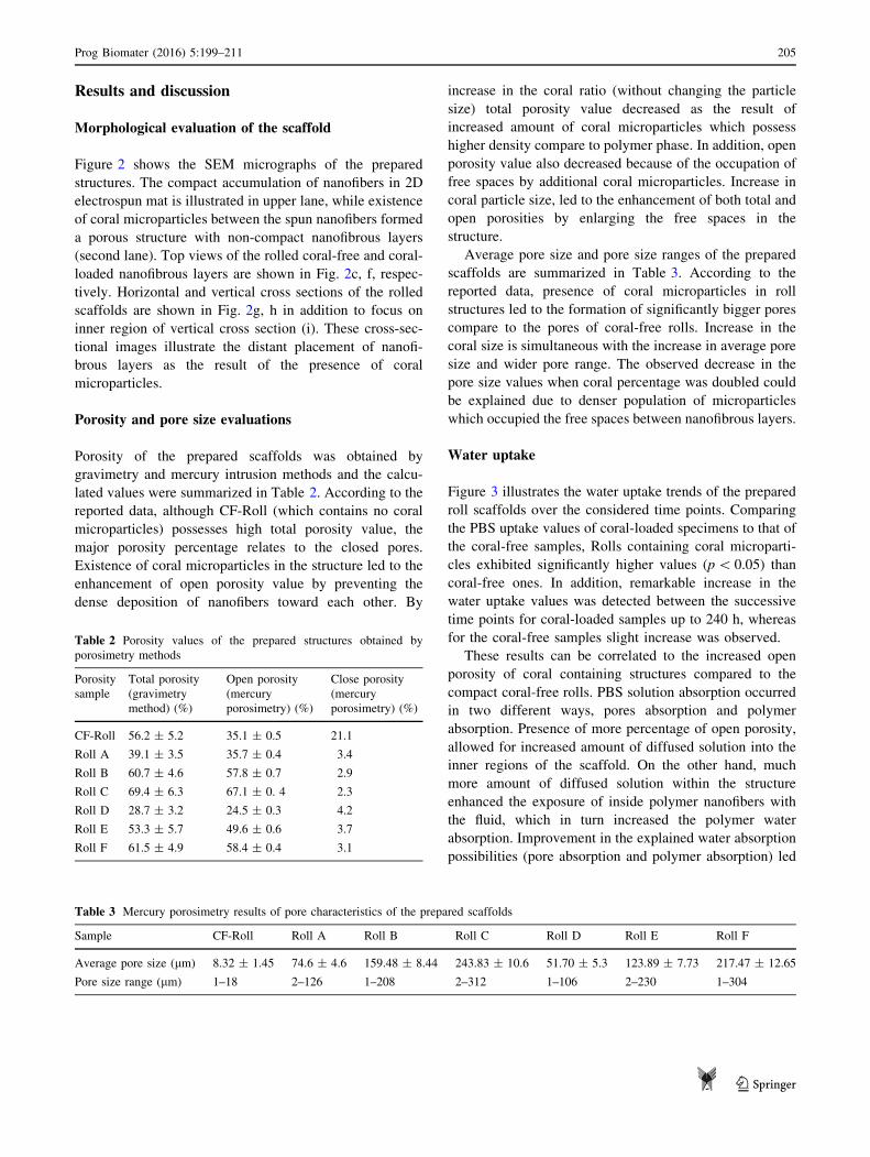
Porosity and pore size evaluations
Porosity of the prepared scaffolds was obtained by
gravimetry and mercury intrusion methods and the calcu-
lated values were summarized in Table 2. According to the
reported data, although CF-Roll (which contains no coral
microparticles) possesses high total porosity value, the
major porosity percentage relates to the closed pores.
Existence of coral microparticles in the structure led to the
enhancement of open porosity value by preventing the
dense deposition of nanofibers toward each other. By
increase in the coral ratio (without changing the particle
size) total porosity value decreased as the result of
increased amount of coral microparticles which possess
higher density compare to polymer phase. In addition, open
porosity value also decreased because of the occupation of
free spaces by additional coral microparticles. Increase in
coral particle size, led to the enhancement of both total and
open porosities by enlarging the free spaces in the
structure.
Average pore size and pore size ranges of the prepared
scaffolds are summarized in Table 3. According to the
reported data, presence of coral microparticles in roll
structures led to the formation of significantly bigger pores
compare to the pores of coral-free rolls. Increase in the
coral size is simultaneous with the increase in average pore
size and wider pore range. The observed decrease in the
pore size values when coral percentage was doubled could
be explained due to denser population of microparticles
which occupied the free spaces between nanofibrous layers.
Water uptake
Figure 3 illustrates the water uptake trends of the prepared
roll scaffolds over the considered time points. Comparing
the PBS uptake values of coral-loaded specimens to that of
the coral-free samples, Rolls containing coral microparti-
cles exhibited significantly higher values (p\ 0.05) than
coral-free ones. In addition, remarkable increase in the
water uptake values was detected between the successive
time points for coral-loaded samples up to 240 h, whereas
for the coral-free samples slight increase was observed.
These results can be correlated to the increased open
porosity of coral containing structures compared to the
compact coral-free rolls. PBS solution absorption occurred
in two different ways, pores absorption and polymer
absorption. Presence of more percentage of open porosity,
allowed for increased amount of diffused solution into the
inner regions of the scaffold. On the other hand, much
more amount of diffused solution within the structure
enhanced the exposure of inside polymer nanofibers with
the fluid, which in turn increased the polymer water
absorption. Improvement in the explained water absorption
possibilities (pore absorption and polymer absorption) led
Table 2 Porosity values of the prepared structures obtained by
porosimetry methods
Porosity
sample
Total porosity
(gravimetry
method) (%)
Open porosity
(mercury
porosimetry) (%)
Close porosity
(mercury
porosimetry) (%)
CF-Roll 56.2 ± 5.2 35.1 ± 0.5 21.1
Roll A 39.1 ± 3.5 35.7 ± 0.4 3.4
Roll B 60.7 ± 4.6 57.8 ± 0.7 2.9
Roll C 69.4 ± 6.3 67.1 ± 0. 4 2.3
Roll D 28.7 ± 3.2 24.5 ± 0.3 4.2
Roll E 53.3 ± 5.7 49.6 ± 0.6 3.7
Roll F 61.5 ± 4.9 58.4 ± 0.4 3.1
Table 3 Mercury porosimetry results of pore characteristics of the prepared scaffolds
Sample CF-Roll Roll A Roll B Roll C Roll D Roll E Roll F
Average pore size (lm) 8.32 ± 1.45 74.6 ± 4.6 159.48 ± 8.44 243.83 ± 10.6 51.70 ± 5.3 123.89 ± 7.73 217.47 ± 12.65
Pore size range (lm) 1–18 2–126 1–208 2–312 1–106 2–230 1–304
Prog Biomater (2016) 5:199–211 205
123

to the increase in overall PBS uptake values of coral con-
taining rolls.
Increase in coral microparticle amount in the structure,
decreased the water uptake rate at early time points
because of initial inhibition toward solution diffusion as the
more microparticles act as barrier in the way of interring
solution. While at further time points, when slow but
continuous diffusion was occurred, because of more distant
placement of nanofibers toward each other as the result of
more in-between microparticles, exposure of nanofibers
and PBS solution intensified and overall PBS uptake values
increased because of more polymer adsorption possibility.
Acoording to the reported data, for all of the prepared
scaffolds no remarkable increase in PBS uptake was
observed between 96 and 240 h which indicates equilib-
rium point for water uptake capasity.
Increase in coral particle size in addition to enhancing
the porosity (which led to the more pore absorption) of the
scaffolds, formed bigger pores in the structure that
increased the PBS uptake rate from early time pints, which
in turn led to the more and accelerated polymer absorption.
Mechanical analysis
To evaluate the mechanical properties of the prepared 3D
nanofibrous scaffolds, compressive mechanical tests were
performed along with the cylindrical axis of the samples.
For each sample, the compressive load was applied up to
50% deformation and representative stress–strain curves
were drawn. Figure 4 represents the r/e curves related to
coral-free verses coral-loaded (1:1, 200 lm) roll. The
specific structure of rolled nanofibrous mat led to obtaining
high modulus and stiffness for CF-Roll scaffold compared
to other reported nanofibrous structures (Shim et al. 2010;
Nguyen et al. 2012; Jennes et al. 2012; Gu et al. 2013;
Sawawi et al. 2013; Lee et al. 2011; Sun et al. 2012;
Wulkersdorfer et al. 2010; Kim et al. 2014; Baker et al.
2012; Milleret et al. 2011). On the other hand, by the
incorporation of stiff coral particles into the polymeric
structure, the r/e curve moved up to higher stress values
and the resultant compressive modulus and stiffness values
Fig. 3 Water uptake behavior in PBS solution up to 240 h for different types of Roll scaffolds. Statistically significant difference is denoted as
* (p\ 0.05)
Fig. 4 Representative compression stress–strain curves of Roll E
specimens
206 Prog Biomater (2016) 5:199–211
123

increased significantly. Compressive mechanical properties
of different types of roll samples are summarized in
Table 4.
According to the reported data, existence of coral
microparticles within the polymer phase with the ratio of
1:1, led to the slight decrease in compression modulus in
small strains. This behavior is mainly related to the col-
lapse of the empty spaces which were formed as the result
of microparticle existence within the scaffold.
In the higher deformations the structure was more
compact, so it was the coral phase which resisted toward
the applied force. As such the significant higher stiffness
and r50% values (p\ 0.05) were detected for coral con-
taining structures compared to coral free ones.
By increasing the coral ratio (from 1 to 2), significant
increase in modulus as well as stiffness and r50% was
observed. This observation can be explained due to the
increased percentage of stiff coral phase which resisted
toward applied force from small deformations.
Increase in coral particle size has dual effect on the
mechanical properties. Increase in the porosity value by
bigger coral microparticles led to the decrease in
mechanical properties, while the required extra force to
break up the bigger particles, increase the mechanical
properties of the samples. In lesser quantities of coral and
smaller deformations, the first effect is more prominent, but
with the further coral ratio and also in higher deformations,
the latter effect would be prevailing.
In vitro cytotoxicity evaluation
DMEM extracts were obtained by immersion of samples
and also coral particles in complete culture medium for 1, 4
and 7 days. The values of Alamar Blue reduced by MG63
cells cultured in presence of the extracts were normalized
to the Alamar Blue values related to the cells in fresh
DMEM incubated for 1, 4 and 7 days. The obtained results
(Fig. 5) indicated good cell viability for the cells which
were cultured in contact with the extracts of the samples as
well as coral microparticles. Considering the eluates of
three time points, no significant difference (p[ 0.05) was
observed for the samples and also coral microparticles.
Cell morphology
Figure 6 shows the SEM images of MG63 cells seeded on
the CF-Roll (First column) and Coral-loaded Roll (second
and third columns) scaffolds at different time points
(SEM images are related to the midline horizontal and
vertical cross sections of the scaffolds). As is illustrated in
these images, seeded cells were detectable on the exterior
surface of CF-Rolls with no considerable migration due to
the compact arrangement of the nanofibrous layers.
Instead, on the coral-loaded rolls, cells spreading and
migration into the inner regions of the scaffold were
remarkable, because of the enhanced pore size and open
porosity between nanofibrous layers as the result of in-
between coral microparticles. In this structure, cells can
migrate between nanofibrous surfaces and in addition to
being in contact with the nanofibrous substrate, can bridge
the surrounding nanofibrous walls instead of just flatten-
ing on the surface.
Cell proliferation
MG63 cells were seeded onto the roll structures up to
21 days; Alamar Blue biochemical assay was performed to
investigate cell viability on the samples at different time
points and the related results are reports in Fig. 7. Com-
pared to the coral-loaded scaffolds, coral-free roll shows
lower cell viability and early stage stop in proliferation
which indicates that the cells did not diffuse into the inner
regions and reach to confluence on the exterior surface of
the scaffold in a short period of time. At the existence of
Table 4 Compressive mechanical parameters determined from
stress–strain curves of the compression tests performed on the 3D
cylindrical Roll scaffolds
Sample Modulus (GPa) Stiffness (GPa) r (50%) (Mpa)
CF-Roll 3.547 ± 0.564 7.144 ± 1.842 2.568 ± 0.715
Roll A 3.052 ± 0.976 10.867 ± 2.379 3.802 ± 0.830
Roll B 2.829 ± 0.713 11.136 ± 1.830 4.058 ± 0.964
Roll C 2.302 ± 0.609 12.110 ± 2.461 4.840 ± 0.776
Roll D 8.247 ± 1.476 17.562 ± 3.679 7.250 ± 1.593
Roll E 7.611 ± 1.057 18.78 ± 3.096 6.928 ± 1.830
Roll F 7.009 ± 0.942 20.62 ± 3.558 7.603 ± 1.761
Fig. 5 Values of Alamar Blue reduced by MG63 cells cultured in
contact with 3D Roll sample eluates at 1 and 4 and 7 days. All the
values are expressed as percentage versus the control
Prog Biomater (2016) 5:199–211 207
123

coral microparticles, by increase in open porosity of the
scaffolds, the probability of cell diffusion enhanced, as
such the proliferation rate and ultimate viable cells on the
related rolls increased as a result of increased area for cell
growth. Increase in coral particle size led to the higher
proliferation values at early time points. This observation
may be due to the fact that bigger particles provide bigger
pores which ease the cellular diffusion into the structure.
But at further time points, when the cells completely
migrate throughout the scaffolds, this is the probability
for the cells in bridging over the nanofibrous layers which
effect the proliferation value. According to the results, by
the use of microparticles with 200 lm average diameter
(Roll B and Roll E), the best situation for cell migration
and growth was provided and subsequently, proliferation
value is significantly higher than when microparticles
with 100 lm diameter was used (Roll A and Roll D). But
when the particles with 300 lm diameter is used (Roll C
Fig. 6 SEM images of MG-63 cells seeded scaffolds at different time points. First column represent the cell seeded CF-Rolls. Second and third
column shows different internal regions of the cell seeded coral-loaded rolls
208 Prog Biomater (2016) 5:199–211
123
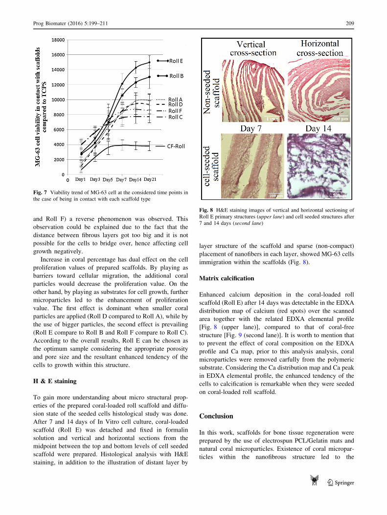
and Roll F) a reverse phenomenon was observed. This
observation could be explained due to the fact that the
distance between fibrous layers got too big and it is not
possible for the cells to bridge over, hence affecting cell
growth negatively.
Increase in coral percentage has dual effect on the cell
proliferation values of prepared scaffolds. By playing as
barriers toward cellular migration, the additional coral
particles would decrease the proliferation value. On the
other hand, by playing as substrates for cell growth, further
microparticles led to the enhancement of proliferation
value. The first effect is dominant when smaller coral
particles are applied (Roll D compared to Roll A), while by
the use of bigger particles, the second effect is prevailing
(Roll E compare to Roll B and Roll F compare to Roll C).
According to the overall results, Roll E can be chosen as
the optimum sample considering the appropriate porosity
and pore size and the resultant enhanced tendency of the
cells to growth within this structure.
H & E staining
To gain more understanding about micro structural prop-
erties of the prepared coral-loaded roll scaffold and diffu-
sion state of the seeded cells histological study was done.
After 7 and 14 days of In Vitro cell culture, coral-loaded
scaffold (Roll E) was detached and fixed in formalin
solution and vertical and horizontal sections from the
midpoint between the top and bottom levels of cell seeded
scaffold were prepared. Histological analysis with H&E
staining, in addition to the illustration of distant layer by
layer structure of the scaffold and sparse (non-compact)
placement of nanofibers in each layer, showed MG-63 cells
immigration within the scaffolds (Fig. 8).
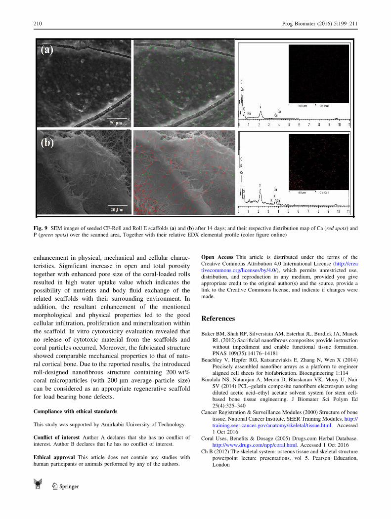
Matrix calcification
Enhanced calcium deposition in the coral-loaded roll
scaffold (Roll E) after 14 days was detectable in the EDXA
distribution map of calcium (red spots) over the scanned
area together with the related EDXA elemental profile
[Fig. 8 (upper lane)], compared to that of coral-free
structure [Fig. 9 (second lane)]. It is worth to mention that
to prevent the effect of coral composition on the EDXA
profile and Ca map, prior to this analysis analysis, coral
microparticles were removed carfully from the polymeric
substrate. Considering the Ca distribution map and Ca peak
in EDXA elemental profile, the enhanced tendency of the
cells to calcification is remarkable when they were seeded
on coral-loaded roll scaffold.
Conclusion
In this work, scaffolds for bone tissue regeneration were
prepared by the use of electrospun PCL/Gelatin mats and
natural coral microparticles. Existence of coral micropar-
ticles within the nanofibrous structure led to the
Fig. 7 Viability trend of MG-63 cell at the considered time points in
the case of being in contact with each scaffold type
Fig. 8 H&E staining images of vertical and horizontal sectioning of
Roll E primary structures (upper lane) and cell seeded structures after
7 and 14 days (second lane)
Prog Biomater (2016) 5:199–211 209
123
enhancement in physical, mechanical and cellular charac-
teristics. Significant increase in open and total porosity
together with enhanced pore size of the coral-loaded rolls
resulted in high water uptake value which indicates the
possibility of nutrients and body fluid exchange of the
related scaffolds with their surrounding environment. In
addition, the resultant enhancement of the mentioned
morphological and physical properties led to the good
cellular infiltration, proliferation and mineralization within
the scaffold. In vitro cytotoxicity evaluation revealed that
no release of cytotoxic material from the scaffolds and
coral particles occurred. Moreover, the fabricated structure
showed comparable mechanical properties to that of natu-
ral cortical bone. Due to the reported results, the introduced
roll-designed nanofibrous structure containing 200 wt%
coral microparticles (with 200 lm average particle size)
can be considered as an appropriate regenerative scaffold
for load bearing bone defects.
Compliance with ethical standards
This study was supported by Amirkabir University of Technology.
Conflict of interest Author A declares that she has no conflict of
interest. Author B declares that he has no conflict of interest.
Ethical approval This article does not contain any studies with
human participants or animals performed by any of the authors.
Open Access This article is distributed under the terms of the
Creative Commons Attribution 4.0 International License (http://crea
tivecommons.org/licenses/by/4.0/), which permits unrestricted use,
distribution, and reproduction in any medium, provided you give
appropriate credit to the original author(s) and the source, provide a
link to the Creative Commons license, and indicate if changes were
made.
References
Baker BM, Shah RP, Silverstain AM, Esterhai JL, Burdick JA, Mauck
RL (2012) Sacrificial nanofibrous composites provide instruction
without impediment and enable functional tissue formation.
PNAS 109(35):14176–14181
Beachley V, Hepfer RG, Katsaneviakis E, Zhang N, Wen X (2014)
Precisely assembled nanofiber arrays as a platform to engineer
aligned cell sheets for biofabrication. Bioengineering 1:114
Binulala NS, Natarajan A, Menon D, Bhaskaran VK, Mony U, Nair
SV (2014) PCL–gelatin composite nanofibers electrospun using
diluted acetic acid–ethyl acetate solvent system for stem cell-
based bone tissue engineering. J Biomater Sci Polym Ed
25(4):325–340
Cancer Registration & Surveillance Modules (2000) Structure of bone
tissue. National Cancer Institute, SEER Training Modules. http://
training.seer.cancer.gov/anatomy/skeletal/tissue.html. Accessed
1 Oct 2016
Coral Uses, Benefits & Dosage (2005) Drugs.com Herbal Database.
http://www.drugs.com/npp/coral.html. Accessed 1 Oct 2016
Ch B (2012) The skeletal system: osseous tissue and skeletal structure
powerpoint lecture presentations, vol 5. Pearson Education,
London
Fig. 9 SEM images of seeded CF-Roll and Roll E scaffolds (a) and (b) after 14 days; and their respective distribution map of Ca (red spots) and
P (green spots) over the scanned area, Together with their relative EDX elemental profile (color figure online)
210 Prog Biomater (2016) 5:199–211
123

Chomachayi MD, Solouk A, Mirzadeh H (2016) Electrospun silk-
based nanofibrous scaffolds: fiber diameter and oxygen transfer.
J Progress Biomater 5:71–80
Feinstein HI (1972) Density of a binary mixture. A classroom or
laboratory exercise. J Chem Educ 49(2):111
Gu BK, Park SJ, Kim MS, Kang CM, Kim JI, Kim CH (2013)
Fabrication of sonicated chitosan nanofiber mat with enlarged
porosity for use as hemostatic materials. Carbohydr Polym 97:65
Hejazi F, Mirzadeh H (2016) Novel 3D scaffold with enhanced
physical and cell response properties for bone tissue regenera-
tion, fabricated by Patterned electrospinning/electrospraying.
J Mater Sci: Mater Med 27:143
Jennes NJ, Wu Y, Clark RL (2012) Fabrication of three-dimensional
electrospun microscope using phase modulated femtosecond
laser pulses. Mater Lett 66:360
John A, Chamberlain JR (1978) Mechanical properties of coral
skeleton: compressive strength and its adaptive significance.
Paleobiology 4(4):419–435
Karageorgiou V, Kaplan D (2005) Porosity of 3D biomaterial
scaffolds and osteogenesis. Biomaterials 26:5474–5491
Kazemnejad S (2009) Hepatic tissue engineering using scaffold, state
of the art. Avicenna J Med Biotechnol 1(3):135–145
Khorshidi S, Solouk A, Mirzadeh H, Mazinani S, Lagaron JM, Sharifi
S, Ramakrishna S (2015) A review of key challenges of
electrospun scaffolds for tissue-engineering applications. J Tissue
Eng Regen Med. doi:10.1002/term.1978
Kidoaki S, Kwon IK, Matsuda T (2005) Mesoscopic spatial designs of
nano- and microfiber meshes for tissue-engineering matrix and
scaffold based on newly devised multilayering and mixing
electrospinning techniques. Biomaterials 26:37–46
Kim YH, Lee BT (2011) Novel approach to the fabrication of an
artificial small bone using a combination of sponge replica and
electrospinning methods. Sci Technol Adv Mater 12:035002
Kim HL, Lee JH, Seo HJ, You KE, Lee MH, Park JC (2014)
Fabrication of three-dimensional poly(lactic-co-glycolic acid)
mesh by electrospinning using different solvents with dry ice.
Macromol Res 22:377
Koh HS, Yong T, Teo WE, Chan CK, Puhaidran ME, Tan TC, Lim A,
Lim BH (2010) Ramakrishna S. In vivo study on novel
nanofibrous intra-luminal guidance channels to promote nerve
regeneration. J Neural Eng 7:046003
Lee JB, Jeong SI, Bae MS, Yang DH, Heo DN, Kim CH, Alsberg E,
Kwon IK (2011) highly porous electrospun nanofibers enhanced
by ultrasonication for improved cellular infiltration. Tissue Eng
A 17:2695
Leung LH, Fan S, Naguib HE (2012) Fabrication of 3D electrospun
structures from poly(lactide-co-glycolide acid)-nano-hydroxya-
patite composites. J PolymSci Part B Polym Phy 50:242
Li WJ, Danielson KG, Alexander PG, Tuan RS (2003) Biological
response of chondrocytes cultured in three-dimensional nanofi-
brous poly(epsilon-caprolactone) scaffolds. J Biomed Mater Res,
Part A 67:1105–1114
Loh QL, Choong C (2013) Three-dimensional scaffolds for tissue
engineering applications: role of porosity and pore size. Tissue
Eng Part B 19(6):485–502
Madurantakam PA, Rodriquez IA, Garg K, McCool JM, Moon PC,
Bowlin GL (2013) Compression of multilayered composite
electrospun scaffolds: a novel strategy to rapidly enhance
mechanical properties and three dimensionality of bone scaf-
folds. Adv Mater Sci Eng 56:1573
Martini FH, TimmonsMJ, Tallitsch RB (2011) Human anatomy, 7th ed.
Pearson, London. ISBN:10:0321688155ISBN 13:9780321688156
Milleret V, Simona B, Neuenschwander P, Hall H (2011) Tuning
electrospinning parameters for production of 3D-fiber fleeces
with increased porosity for soft tissue engineering applications.
Eur Cells Mater 21:286
Nam J, Huang Y, Agarwal S, Lannutti J (2007) Improved cellular
infiltration in electrospun fiber via engineered porosity. Tissue
Eng 13:2249–2257
Netter FH (1987) Musculoskeletal system: anatomy, physiology, and
metabolic disorders. Ciba-Geigy Corporation, Summit, New
Jersey
Nguyen LTH, Liao S, Chan CK, Ramakrishna S (2012) Enhanced
osteogenic differentiation with 3D electrospun nanofibrous
scaffolds. J Nanomed 7(10):1561–1575
Pezeshki-Modaress M, Rajabi-Zeleti S, Zandi M, Mirzadeh H, Sodeifi
N, Nekookar A, Aghdami N (2014) Cell loaded gelatin/chitosan
scaffolds fabricated by salt-leaching/lyophilization for skin
tissue engineering: in vitro and in vivo study. J Biomed Mater
Res A 102(11):3908–3917
Pham QP, Sharma U, Mikos AG (2006) Electrospun poly(epsilon-
caprolactone) microfiber and multilayer nanofiber/microfiber
scaffolds: characterization of scaffolds and measurement of
cellular infiltration. Biomacromolecules 7:2796–2805
Ru C, Wang F, Ge C, Luo J (2013) A multifunctional electrospinning
system for manufacturing diversified nanofibrous structures. Rev
Sci Instrum 84:086107
Sawawi M, Wang TY, Nisbet DR, Simon GP (2013) Scission of
electrospun polymer fibres by ultrasonication. Polymer 54:4237
Shim IK, Jung MR, Kim KH, Seol YJ, Park YK, Park WH, Lee SJ
(2010) Novel three-dimensional scaffolds of poly(L-lactic acid)
microfibers using electrospinning and mechanical expansion:
fabrication and bone regeneration. J Biomed Mater Res Part B
Appl Biomater B 95:150–160
Sun B, Long YZ, Yu F, Li MM, Zhang HD, Li WJ, Xu TX (2012)
Self-assembly of a three-dimensional fibrous polymer sponge by
electrospinning. Nanoscale 4:2134
Szentivanyi A, Chakradeo T, Zernetsch H, Glasmacher B (2011)
Electrospun cellular microenvironments: understanding con-
trolled release and scaffold structure. Adv Drug Deliv Rev
63:209–220
Thorvaldsson A, Stenhamre H, Gatenholm P, Walkenstrom P (2008)
Electrospinning of highly porous scaffolds for cartilage regen-
eration. Biomacromolecules 9:1044–1049
Tong HW, Wang M (2013) A novel technique for the fabrication of
3D nanofibrous scaffolds using simultaneous positive voltage
electrospinning and negative voltage electrospinning. Mater Lett
94:116
Wulkersdorfer B, Kao KK, Agopian VG, Ahn A, Dunn JC, Wu BM,
Stelzner M (2010) Bimodal porous scaffolds by sequential
electrospinning of poly(glycolic acid) with sucrose particles. Int
J Polym Sci. doi:10.1155/2010/436178
Xiao C, Zhou H, Ge S, Tang T, Hou H, Luo M, Fan X (2010) Repair
of orbital wall defects using biocoral scaffolds combinedwith
bone marrow stem cells enhanced by human bonemorphogenetic
protein-2 in a canine model. Int J Mol Med 26:517–525
Prog Biomater (2016) 5:199–211 211
123