rockwell compactlogix or controllogix to omron nx-csg320 ... · compactlogix io module status from...
TRANSCRIPT

OMRON Rockwell CompactLogix or ControlLogix
To Omron NX-CSG320 + NX-SL5700
EtherNet/IP Implicit Messaging Quickstart Guide
Version 1.0
3/9/2018

Section 1: Introduction
This document will allow the user to setup an Ethernet/IP Tag Datalink (Implicit Messaging)
connection between a Rockwell ControlLogix or CompactLogix PLC and an Omron NX-SL5700
safety CPU, through an NX-CSG320 communications gateway.
In this configuration, the NX-SL5700 is performing the machine safety functions, incorporating
devices such as door switches, safety area scanners, ESTOP buttons, force guided relays,
remote safety IO blocks, robots with CIP Safety capabilities, and other safety components.
The PLC is performing only non-safety functions such as the monitoring of the safety devices for
annunciation on an HMI.
Tags can be mapped from 2 different places when using an NX-CSG320 and an NX-SL5700.
Tags can be mapped from the Safety CPU to the Gateway, and then mapped to Ethernet/IP, or
status information from local NX safety IO connected directly to the NX-CSG320 can be
mapped directly to EtherNet/IP.
This Tag Datalink (Implicit Messaging Connection) will share:
2 boolean data points from the ControlLogix through the NX-CSG320 to the NX-SL5700
6 boolean data points from the NX-SL5700 through the NX-CSG320 to the
CompactLogix
IO Module status from local NX Safety IO from the NX-CSG320 to the CompactLogix.
This document will explain both of these mapping methods.
Note: the names of the NX-SL5700 and NX-CSG320 as shown in Sysmac Studio have been
changed from the default for clarity.

Section 2: Mapping data from the NX-SL5700 to the NX-CSG320
Mapping data from the NX-SL5700 to the NX-CSG320 is used when internal values from the
safety program need to be exposed on EtherNet/IP, such as the state of Function Block, as
shown below. In this example ESTOP_1_Monitor only turns on when the ESTOP button is not
pressed in, and the RESET_IN signal has been applied to reset the Emergency Stop function
block.

1. In Sysmac Studio, create the 8 Global Variables in the NX-SL5700 Safety CPU. 2 are
‘Input’ and 6 are ‘Output’ in the Expose Column. The 6 outputs are intended to show
the monitoring of internal safety status in the safety CPU, and the 2 inputs are non-safe
auxiliary inputs from the PLC, used for non-safety functions such as auxiliary lamps.

Section 3: Mapping data from the NX-CSG320 to EtherNet/IP
1. At the top of the Multiview Explorer, select the Communications Gateway device, and
then double click IO Map.
2. On the IO Map, enter variable names in the NX-CSG320 that match the names shown
on the left in the NX-SL5700. It is not required that the names match, but for ease of
programming, it is recommended that they do match. This step connects the Tags it the
NX-SL5700 Safety CPU to Tags in the NX-CSG320 gateway.

3. To map the logical values (on/off state) and status of local NX Safety IO located on the
IO bus local to the NX-CSG320 and NX-SL5700, add variables to the IO Map for NX
safety modules as shown.
4. Double click Global Variables.

5. In the Global Variables, change the Network Publish to Output for the Door, Scanner,
ESTOP, Logical Values and IO Status tags, and Input for the Lamp control Tags. This
makes the Tags available to be used in an EtherNet/IP connection.
6. To begin the EtherNet/IP setup, select Tools, EtherNet/IP Connection Settings.
7. Double click on the top port (Built-in EtherNet/IP Port Settings – Port 1).

8. Click Registration All to import the Global Variables into the EtherNet/IP configuration.
9. Click Register. This creates a Tag Set (assembly) for each Tag. In steps 10 through
12, the individual Input Tag Sets will be consolidated into a single Tag set.
10. Select and Delete Tag Set Lamp_2_Control, leaving only 1 Tag Set (Lamp_1_Control).

11. Right click Lamp_1_Control and select Create New Tag.
12. Type ‘L’ to activate the drop down list of all tags beginning with ‘L’ and select
Lamp_2_Control.
13. Click twice slowly on the Tag Set Name Lamp_1_Control, and rename it ‘Inputs’. Note:
this is not a necessary step, but is done to distinguish Tags and Tag Set names.

14. On the Inputs Tag Set, click ‘Auto’ in the Instance ID column, and change it to 110. This
sets assembly 110 as the Input assembly, which will be used in the configuration of the
CompactLogix connection.
15. Select the Output tab.

16. Repeat steps 10 – 12 for the Output Tag Sets, deleting Tag Sets Door_2_Monitor,
Scanner_1_Monitor, Scanner_2_Monitor, ESTOP_1_Monitor, and ESTOP_2_Monitor.
Add those Tags back to the Door_1_Monitor Tag Set.
17. Click twice slowly on the Tag Set Name Door_1_Monitor, and rename it ‘Outputs’. Note:
this is not a necessary step, but is done to distinguish Tags and Tag Set names.
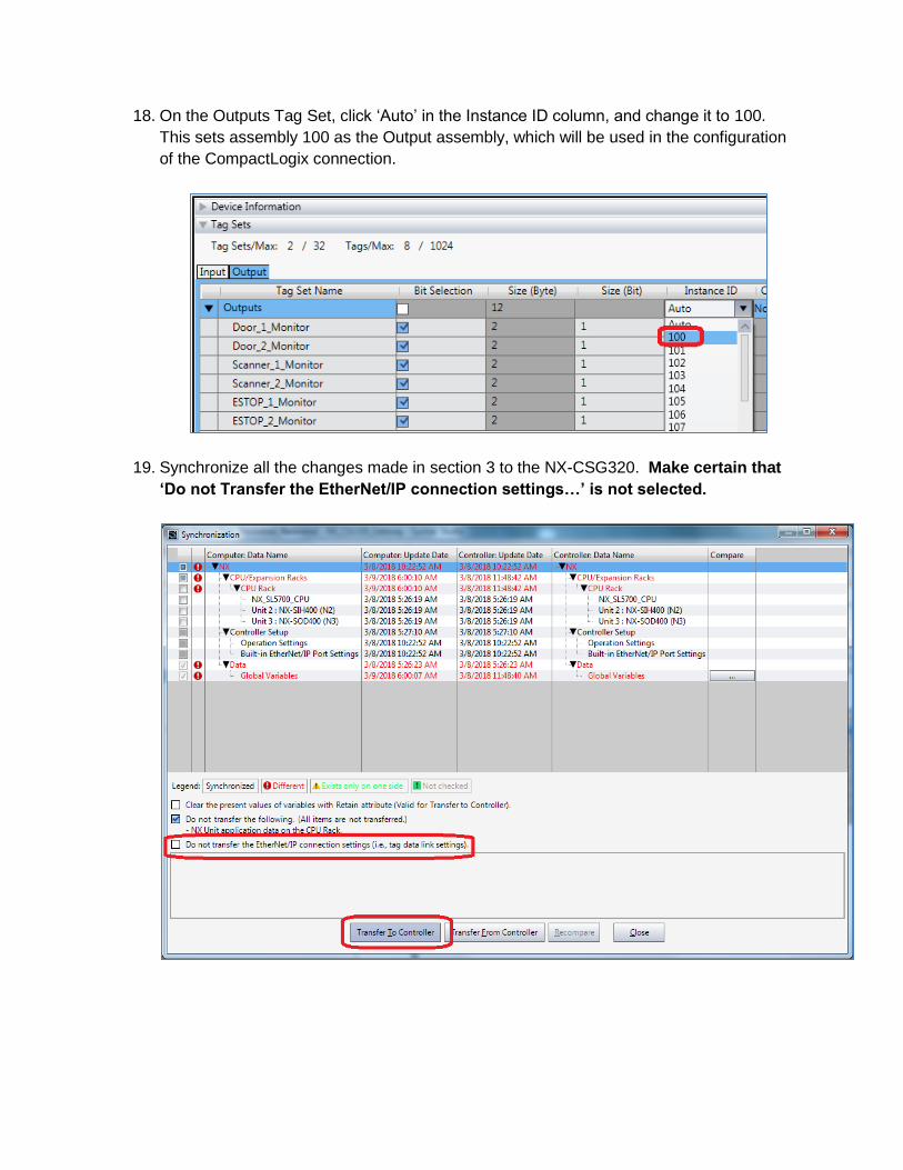
18. On the Outputs Tag Set, click ‘Auto’ in the Instance ID column, and change it to 100.
This sets assembly 100 as the Output assembly, which will be used in the configuration
of the CompactLogix connection.
19. Synchronize all the changes made in section 3 to the NX-CSG320. Make certain that
‘Do not Transfer the EtherNet/IP connection settings…’ is not selected.
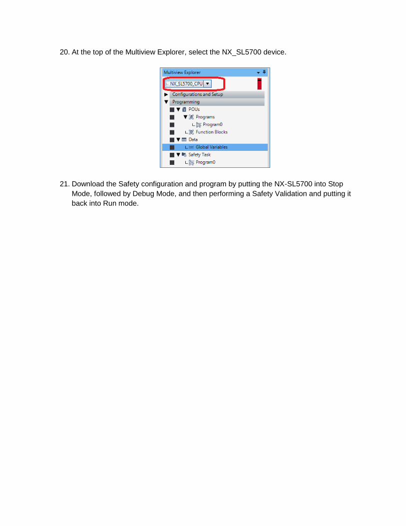
20. At the top of the Multiview Explorer, select the NX_SL5700 device.
21. Download the Safety configuration and program by putting the NX-SL5700 into Stop
Mode, followed by Debug Mode, and then performing a Safety Validation and putting it
back into Run mode.

Section 4: CompactLogix Configuration
1. Open an existing project file or create a new project file for the CompactLogix in
RSLogix 5000 or Studio 5000.
2. Configure the IP address of the CompactLogix as 192.168.1.77 using RSLogix 5000 (as
an example IP Address).
3. In RSLogix 5000, right click on the Ethernet module in the CompactLogix, and click
‘New Module’.
4. In the ‘Communications’ group, select ‘ETHERNET-MODULE Generic Ethernet
Module’, and click ‘OK’.
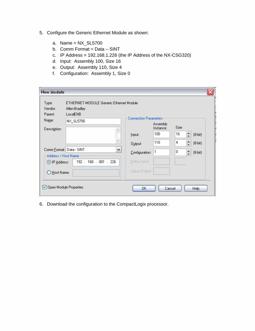
5. Configure the Generic Ethernet Module as shown:
a. Name = NX_SL5700
b. Comm Format = Data – SINT
c. IP Address = 192.168.1.226 (the IP Address of the NX-CSG320)
d. Input: Assembly 100, Size 16
e. Output: Assembly 110, Size 4
f. Configuration: Assembly 1, Size 0
6. Download the configuration to the CompactLogix processor.

Section 5. Monitoring the Data:
Data mapped from the NX-SL5700 uses at least 2 bytes of data for each tag, regardless
of the data type. Based on the order of the Tags in the Input Tag Set and Output Tag
Set, the data flow would be as shown: