rockets and launchers, all types. pt3 - murdercube.com arms/rocketspt3.pdf · the m4 p.d rocke. t...
TRANSCRIPT

DECLASSIFIED M4A1 FUZE
SECTION V
4.5" ROCKET FUZE DEVELOPMENT
87 GENERAL The M4 P.D. rocket fuze as
sembled with the M8 rocket has undergone change since its standardization. Two successive major changes resulted in the M4A1 and the M4A2 fuzes. These changes and the modified fuzes are discussed in the following paragraphs.
88 FUZE, P.D., M4A1 a. The principal changes in the
.M4 fuze (see fig. 37) to produce the M4A1 fuze are as follows:
(1) A different delay time has been provided. Approximately 40 percent of the present production of M4A1 fuzes retain the .1-sec. delay found in the M4 fuze. Such fuzes are for ground use only. The remaining production quantities of the M4A1 fuze have a .015-sec. delay. This delay was r e quested by the Army Air Forces, and fuzes having this delay are for air use only. The short-delay charge consists of approximately .136 grain of Army black powder, grade A-5, compressed at a pressure of 60,000 lb./sq.in. The .1-sec. delay charge consists of 1.23 grains of a similar powder pressed under a similar pressure. The dimensions of the delay-element housing depend on the type of delay charge used. When the delay charge is inserted in the small central cavity, the long narrow hole below the compression chamber is 1.520" long; when the short-delay charge is inserted, the hole is .355" long. The difference in length of this hole is obtained by increasing the length of the compression chamber. The different delay times will be included as part of the nomenclature of the fuze and will appear stamped on the fuze. Requests for the fuze should specify the delay time required.
(2) The walls of the fuze have been made thinner so as to reduce the total weight of the fuze.
(3) With the use of the two-zone propellant in the modified M8 rocket, it was found necessary to reduce the spring tension so that a lower acceleration would arm the fuze. The M4 fuze required 160 G. to arm (in later production models this requirement was reduced to 100 G.); the M4A1 r e quires 100 G. to arm.
b. Upon completion of the present production program for the M4A1 fuze, it is contemplated that the fuze w i l l be declared limited standard. Production of the M4A2 will begin on a large scale, and issues of the M4A1 will be made until stocks are exhausted.
89 FUZE, P.D., M4A2 The M4A2 rocket fuze (see fig.
60) differs from the M4 and M4A1 in the following respects:
a. The body has been redesigned to seat a new type of setting pin. In the M4 and M4A1 fuzes when the setting pin was not rotated completely through 180°, the flash holes in the setting pin were not alined with the body flash hole and the delay and instantaneous flash holes; the setting pin presented a solid metal surface to the flame from either the super quick or delay elements, and the fuze would not function completely. When this condition existed, the rocket became a dud. To obviate this difficulty, the arrangement illustrated in figure 60 was devised. An oblique hole, 5/32" in diameter, is drilled from the upper rim of the delay-arming-pin hole to the body flash hole. Into this
-80

&SCUSSIFIED M4A2
hole, at a 25° angle, is fitted the delay element. The flash from the delay element is thus certain to pass unobstructed through the body flash hole and set off the slider detonator no matter whether the setting pin is set correctly or not.
b. The new setting pin is 1.33" long and has a single diagonal flash hole passing through the unslotted end. This flash hole is .218" in diameter and is set at angle of 28°.
FIG 59 SETTING PIN
FUZE
c. The slider for t h e M4A2 fuze is made of aluminum, affecting a considerable reduction in weight. At the same time, the lockingpinhas been strengthened (see fig. 60). The combination of these two changes has done much to prevent malfunctions of the fuze during ricochet. In the M4 and M4A1 fuzes, the heavy slider occasionally sheared the weaker locking pin and slid back into the unarmed position. Such a malfunction is unlikely to occur now.
d. Another change is the use of a lead-brass forged body as a third alternative. This is in addition to the malleable-iron and gray-iron castings previously specified.
DECLASSIFIED -81

M4A2 FUZE
DECLASSIFIED -82

DECLASSIFIED 4.5*
LAUNCHERS
SECTION VI
4.5" ROCKET LAUNCHERS
90 GENERAL a. Launchers for rockets, 4.5"
and larger, are of three general classifications.
(1) Air-to-ground or air-to-air launchers are mounted on aircraft and are used to launch rockets at ground targets or at other aircraft.
(2) Ground-to-ground launchers are mounted on vehicles or emplaced on the ground and are used to launch rockets at ground targets.
(3) Antiaircraft launchers are mounted on vehicles or emplaced on the ground and a r e used to launch rockets at aircraft. They are not used by the United States Army.
b. There are three types of ground-to-ground launchers.
91 LAUNCHER, ROCKET, MULTIPLE ARTILLERY, 4.5% T27 AND T27E1
a. D e s c r i p t i o n . — The T27 launcher (see figs. 61 and 62), designed to provide a light and highly mobile weapon of great fire power for groundto-ground use, is an eight-tube launcher. It maybe mounted on a 1-1/2-ton truck or assembled for ground fire at a selected position. This weapon is in the development stage. A second pilot, which will be designated T27E1, is being designed for breakdown into two-man loads not exceeding 120 lb. each.
b. Principal characteristics.
No. of tubes 8
Elevation -5° to +45°
Traverse • Provided by turning truck, or by shifting trail in ground fire.
Firing mechanism-Electric, p e r m i t ting single-round or ripple fire.
Blast protection for crew None
Sighting equipment • For indirect f i r e on ly .
Weight
c_. Ripple fire.— Ripple fire refers to the setting of the firing mechanism that permits the rockets to be launched one after another at short intervals.
92 LAUNCHER, ROCKET, MULTIPLE ARTILLERY, 4.5", T34
a. Description.— This groundto-ground launcher (see fig. 63), now under development, will be mounted on the turret of an M4 medium tank. It is of the expendable type, composed of 60 opaque plastic tubes which may be jettisoned at will. The rockets are fired electrically, either singly or in ripple fire. Elevation is from -5° to +30° by means of the elevating mechanism of the gun in the turret. Traverse is accomplished by movement of the t u r r e t . Al l 4.5" ground-to-ground rockets may be used in this launcher. T h e launcher weighs approximately 1,800 lb.
b. Principal characteristics.
No. of tubes - 60
Elevation -5° to +30°
Provided by rotat-Traverse ing turret.
Firing mechanism- Electric, permi t ting single-round or ripple fire.
-83 DECLASSIFIED

T36 DECkASSIBED
LAUNCHER
•Bfafcft Tank itself.
Sighting equipment—Tank equipment.
Weight (approx.) 1,800 lb.
93 LAUNCHER, ROCKET, MULTIPLE ARTILLERY, 4.5", T36
a. D e s c r i p t i o n . — This is a ground-to-ground launcher with eight light steel tubes. It can be fired from the ground or installed on a 1/4-ton 4 x 4 truck. Firing is electrical, in single rounds or in ripple fire. Elevation is from -5° to +35°. When mounted in the 1/4-ton truck, the launcher is traversed by movement of the vehicle. When the launcher is used as a ground weapon, it can be traversed through 20°. This launcher is under development.
b. Principal characteristics.
No. of tubes 8
Elevation -5° to +45°
Traverse: Truck-mounted Provided by turn
ing truck. Ground-emplaced 20°
Firing mechanism-Electric, p e r m i t ting single-round or ripple fire.
Blast protection
Sighting equipment
Weight
DECLASSIFIED -84

DECLASSIFIED T27 LAUNCHER
DECLASSIFIED -85

DECLASSIFIED T27 LAUNCHER
FIGURE 62. - T27 LAUNCHER MOUNTED ON 1-1/2-TON 6 X 6 PERSONNEL, CARRIER. TOP: FRONT, 45° ELEVATION. BOTTOM: THREE-QUARTER.' LEFT FRONT, -5° DEPRESSION
-86- DECLASSIFIED

T34 DECLASSIFIED LAUNCHER
FIGURE 63. - T34 LAUNCHER ON MEDIUM TANK, M4-TYPE<
DECLASSIFIED -87

NOTES

NOTES
-89

7.2" DECLASSIFIED ROCKETS
CHAPTER 5-7.2" ROCKETS AND LAUNCHERS
SECTION I
ROCKET, H.E., 7.2", T14
94 ROCKET H.E., 7.2", T14 The muzzle velocity is approximately This rocket was designed to 920 ft./sec, and the maximum range
carry a powerful demolition charge. It is approximately 6,000 yd. The Fuze, is propelled by a fast-burning double Tl, and Fuze, Mk. 137 (Navy), are used base powder in extruded stick form. with this rocket.
SECTION II
ROCKET, CHEMICAL, 7.2", T15
95 ROCKET, CHEMICAL, 7.2", T15 H.E. head used with the T14. The T15 weighs approximately 701b. The mini-
The T15 rocket is similar to the mum range for this projectile is 500 yd. T14 rocket except for substitution of a The Tl and Mk. 137 (Navy) fuzes are chemical-loaded head in place of the used.
SECTION III
ROCKET, H.E., AT, 7.2", T16
96 ROCKET, H.E., AT, 7.21, T 17 T14 rocket except that it has a highThis rocket is the same as the explosive antitank head.
SECTION IV
ROCKET, PRACTICE, 7.2", T17
97 ROCKET, PRACTICE, 7.2", T 17 inert head substituted for the H.E. head This is the T14 rocket with an on the T14.
DECLASSIFIED -90

NOTES
-91

NOTES
-92
DECLASSIFIED T ROCKET
SECTION V
ROCKET, CHEMICAL, 7.2", T21
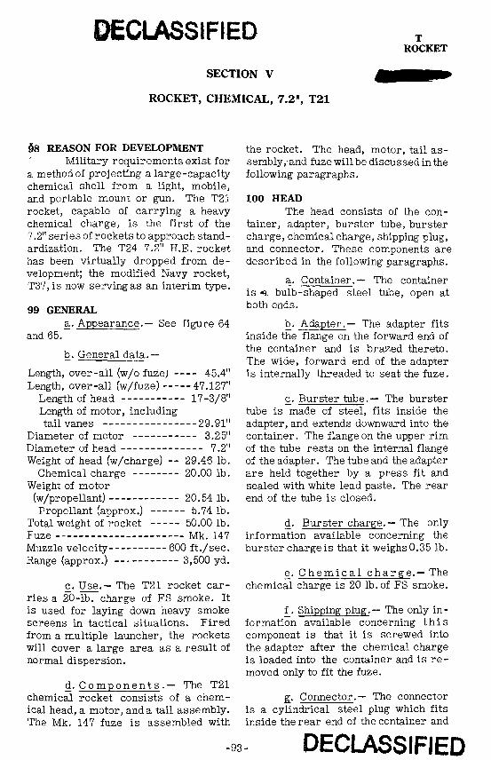
§8 REASON FOR DEVELOPMENT Military requirements exist for
a methodof projecting a large-capacity chemical shell from a light, mobile, and portable mount or gun. The T21 rocket, capable of carrying a heavy chemical charge, is the first of the 7.2" series of rockets to approach standardization. The T24 7.2" H.E. rocket has been virtually dropped from development; the modified Navy rocket, T37, is now serving as an interim type.
99 GENERAL a. Appearance.— See figure 64
and 65.
b. General data.—
Length, over-all (w/o fuze; 45.4" Length, over-all (w/fuze) 47.127"
Length of head 17-3/8" Length of motor, including tail vanes 29.91"
Diameter of motor 3.25" Diameter of head - - - 7.2" Weight of head (w/charge) - - 29.46 lb.
Chemical charge 20.00 lb. Weight of motor
(w/propellant) 20.54 lb. Propellant (approx.) 5.74 lb.
Total weight of rocket 50.00 lb. Fuze Mk. 147 Muzzle velocity 600 ft./sec. Range (approx.) 3,500 yd.
c. Use.— The T21 rocket carries a 20-lb. charge of FS smoke. It is used for laying down heavy smoke screens in tactical situations. Fired from a multiple launcher, the rockets will cover a large area as a result of normal dispersion.
d. Components .— The T21 chemical rocket consists of a chemical head, a motor, and a tail assembly. The Mk. 147 fuze is assembled with
the rocket. The head, motor, tail assembly, and fuze will be discussed in the following paragraphs.
100 HEAD The head consists of the con
tainer, adapter, burster tube, burster charge, chemical charge, shipping plug, and connector. These components are described in the following paragraphs.
a. Container.— The container is «. bulb-shaped steel tube, open at both ends.
b. Adapter.— The adapter fits inside the flange on the forward end of the container and is brazed thereto. The wide, forward end of the adapter is internally threaded to seat the fuze.
c. Burster tube.— The burster tube is made of steel, fits inside the adapter, and extends downward into the container. The flange on the upper rim of the tube rests on the internal flange of the adapter. The tube and the adapter are held together by a press fit and sealed with white lead paste. The rear end of the tube is closed.
d. Burster charge.— The only information available concerning the burster charge is that it weighs 0.35 lb.
e. C h e m i c a l charge.— The chemical charge is 20 lb.of FS smoke.
f_. Shipping plug.— The only information available concerning t h i s component is that it is screwed into the adapter after the chemical charge is loaded into the container and is re moved only to fit the fuze.
g_. Connector.— The connector is a cylindrical steel plug which fits inside the rear end of the container and
-93 DECLASSIFIED

DECLASSIFIED T21 ROCKET
-94- DECLASSIFIED

T21 DECLASSIFIED ROCKET
o
-95 DECLASSIFIED

DECLASSIFIED T21
ROCKET
is brazed thereto. The rear portion of the connector is threaded internally to seat the forward end of the motor body.
101 MOTOR a. A p p e a r a n c e . — Figure 64
gives a cross section of the riaotor and its components.
b. Components. — The m o t o r consists of a motor body, shipping cap, venturi tube, grid, and the propellant assembly. In the following subparagraphs the first four of these components will be described. The propellant assembly will be discussed in a separate paragraph.
(1) Motor body.— The motor body is a steel tube .11" thick and 28.935" long. It is tapered near the rear end. This taper commences approximately 7" from the rear end and ceases approximately 4"from that end. The rear portion of the body has a diameter of 2.755". The forward end of the tube is externally threaded through 1" of its length and fits inside the connector of the head.
(2) Shipping cap. — The shipping cap, made of drab-colored plastic, is shaped as shown in figure 66. The walls a r e internally threaded to f i t t he threaded end of the motor body. Two winglike projections on the upper surface of the cap assist in screwing on the cap.
(3) Venturi tube.— The venturi tube is shown in figure 67. It is slipped down through the large, open end of the motor body, and the end B is welded to the inner edge of the motor-body rim. The tube is steel and has the shape and dimensions illustrated in figure 67. The hole C is .125" in diameter and allows gas to escape into the space between tube and motor body. Gas in this cavity tends to equalize the pressure on both sides of the venturi tube and prevent its distortion.
(4) Grid.— The grid consists of four steel pieces, each notched as shown in A, figure 68. These four pieces are interlocked to form the assembly shown in B, figure 68. Each end of each piece is rounded to fit the internal surface of the motor body. The grid is dropped down through the large opening in the motor body and comes to rest crosswise on the upper rim of the venturi.
_̂_ A ~I375~ (-.187
I 1
L 1\ B A c •A
—2gMAX--\ h-2.75 ROUC FIG.68 GRID
102 PROPELLANT ASSEMBLY This assembly is a part of the
motor assembly, but for sake of simplicity of presentation it is described in this separate paragraph. The propellant assembly consists of the propellant-powder assembly, closure disk, spring, igniter assembly, desiccant assembly, and tail plug. These compo-
DECLASSIFIED -96

DECLASSIFIED T21
ROCKET
nents are described in subparagraphs a through f_ below; in subparagraph g_, the assembly and functioning of the propellant are discussed.
a. Propellant-powder assembly. This assembly consists of four sticks of propellant powder and four propellant-powder washers. Each of t he four washers is cemented to one end of the four sticks. The propellant is ignited at its forward end rather than at its rear end as was the case in the previously discussed rockets.
(1) Propellant powder. —A stick of propellant powder is 20.5" long and has a 1" axial hole. The view in figure 69 shows the three longitudinal ridges on the surface of the stick. There are eight sets of three holes each in each stick. Figure 69 shows the relative position of one set of holes. These holes make the propellant stick burn more evenly.
r-|DIA.-24 HOLES
FIG.69 PROPELLENT POWDER
(2) Propellant-powder washer. The washer is made of celluloid 1/8" thick. The external d i a m e t e r is 2-15/32", and the internal diameter is 1-3/64".
b. Closure disk.— The closure disk is of black, hard fiber 3.03" in diameter and 1/8" thick.
c. Spring.— The spring is made of annealed steel and has the shape and dimensions shown in figure 70. The spring is welded to the face of the igniter cap (see fig. 64).
ir1
1/
1 i
)
;
T"
t
» r> .9. - 1 6
FIG. 70 SPRING
d. Igniter assembly.— The igniter assembly consists of an igniter c a p , igniter holder, electric squib, and igniter charge. These igniter components will be described in the following subparagraphs.
(1) Igniter cap. — The igniter cap is 2.375"in diameter and3/8"deep. It is made of steel .0179" thick.
(2) Igniter holder. —The igniter holder is made of clear plastic and has the shape and dimensions illustrated in figure 71. The electric squib is slipped into the axial hole of the igniter holder. After the igniter charge is pouredinto the igniter cap, the holder is cemented to the cap (see fig. 64.)
FIG. 71 IGNITER HOLDER
(3) Electric squib. - The squib is a commercial electric igniter with
-97 DECLASSIFIED

T21 DECLASSIFIED ROCKET
two plastic-coated lead wires, each 24" long. The free ends of the lead wires are stripped for a distance of 1". To each stripped end, 12" of insulated lead wire is bound with friction tape. The free ends and tha taped ends of each of these second lengths of wire are stripped for 3/4". One wire is attached to the terminal on the front shroud of the tail assembly, and the other is attached to the rear-shroud terminal.
(4) Igniter charge.— The igniter charge is black powder.
e. Desiccant assembly. — The desiccant assembly consists of three 5" squares of cheesecloth bound into a bag. The bag contains 30 to 35 grains of silica gel. This assembly absorbs moisture and prevents the moisture content of the propellant from becoming too high.
f_. Tail plug.— The tail plug is black, hard fiber, 1/8" thick and 2.25" in diameter. Opposite each other on the rim of the plug are two small notches.
g. Assembly and functioning. (l) Assembly.— The four propellant sticks with washers attached are inserted in the threaded end of the motor body, washer ends first, and rest on the grid. The igniter assembly is then inserted in the same end; the wires are drawn through the venturi tube. The projection on the igniter holder spaces the propellant sticks. The closure disk is fitted into the motor body, pressed down upon the spring, and cemented in place. The tension of the spring holds the igniter firmly against the propellant sticks, holding the latter in place. The desiccant assembly is placed in the venturi tube. The tail plug is inserted in the rear of the venturi tube with one igniter lead wire in eachnotch. The tail plug is cemented in place.
(2) Functioning. — When electric current is turned on, the squib explodes
DECLASSIFIED -98
and sets off the igniter charge. The flame of the igniter charge starts the inside and outside of the upper half of each propellant stick burning. The rapid burning of the sticks results in a high gas pressure that provides the motive power for the rocket.
103 TAIL ASSEMBLY The tail assembly serves to
stabilize the rocket in flight and as a contact point for the electric current that explodes the igniter. The tail assembly consists of two tail vanes, a front and rear shroud, and four fins. The components a r e described as follows:
a. Tail vanes.— Each vane is made of steel and is shaped roughly like a W. The curved middle portion A (see fig. 72) is welded to the rear outer surface of the motor body. The feet of the vanes, labeled B, support the front and rear shrouds. The rear shroud is welded to end B", and the front shroud is riveted to end B' through the holes C.
b. Front shroud.— The front shroud is a steel ring 7.20" in diameter and 1.94" high. Equally spaced about the ring are four pairs of holes. The front shroud is slipped over the feet of the vanes, and the holes in the shroud and in the feet are alined. Shroud and vanes are fastened by means of insulated rivets. A terminal for one of the igniter lead wires is attached to the inner surface of the shroud.
c. Rear shroud. — The r e a r shroud is identical to the front shroud
-

T21 ROCKET
except that it has no holes and is welded at three points to each vane foot. The rear shroud is assembled with a .12" gap between it and the front shroud. A termini for the other igniter lead wire is attached to the inner surface of the shroud.
vid. Fin. — The steel fins a r e welded to the outside of the motor body just forward of the taper. Area A is welded to the motor body, and end B is welded to blade C of an adjacent fin (see fig. 73). End D extends rearward along the motor body, and the edge E is welded to the outer surface of the rear shroud
104 FUZE, MK. 147 (NAVY) a. General.— The Army pro
cures this fuze from the Navy. It is 2.414" long and 1.750" in greatest diameter (see fig. 74). The threads just below the shoulder engage those in the adapter of the T21 rocket. Into the bottom of the fuze is screwed an adapter that seats the burster. This burster ruptures the case and scatters t h e chemical contents of the rocket. The fuze is made of cadmium-plated steel and weighs approximately 1/2 lb. without the burster.
b. Action. - (1) The fuze i s shipped with the components in the position shown in figure 74. After the fuze is screwed into the rocket, the following steps are taken prior to firing:
(a) The shipping-guard tape is removed. This tape is wrapped in a clockwise direction over the shipping
guard and body in such a manner as to extend over and completely cover the body shoulder.
(b) The shipping guard is r e moved. This is a brass cup with a rounded bottom that fits over the propeller assembly and is held in place on the body shoulder by the shipping-guard tape. The removal of t h e shipping guard exposes the propeller assembly and the upper half of the body.
(c) The safety wire is removed. On the safety wire is a white tag, 3"x 1". In black letters appears the following information:
REMOVE SAFETY WIRE
over (obverse)
REPLACE SAFETY WIRE
IF ROUND IS UNFIRED
over (reverse)
The underlined words are in red. The removal of the safety wire permits movement of the set-back pellet when sufficient acceleration is gained.
(2) When the rocket i s fired the set-back pellet moves to the rear against the tension of the set-backpellet spring. The propeller locking pin, which is staked to the pellet and extends through a hole in the body, moves to the rear with the pellet. This rearward movement of pellet and pin frees the propeller assembly and permits it to rotate.
(3) The propeller assembly begins to spin. After 2.1 turns it has moved outward far enough so that the propeller lock pin on returning to its
-99 DECLASSIFIED

T21 DECLASSIFIED ROCKET
z 0.
Q CO
^ X D O cc <r
LU UJ O _J izId
dl
LU iLU a. Q.O O
X en octo a.
w
DECLASSIFIED -100

DECLASSIFIED T21 ROCKET
forward position, cannot act as a positive lock. The fuze is not yet armed. The propeller assembly continues to rotate, and is unscrewed from the body. The assembly then rotates freely, for it is free of the body threads, which are riding in the groove next to the shoulder of the pin. The point of the firing pin has withdrawn into the central hole of the closure plate, freeing the shutter. The shutter can now move.
(4) The shutter, cocked by the "mouse-trap" shutter spring, rotates clockwise until it is stopped by the closure-plate pin. In this position, the detonator assembly, housed in the central shutter hole, is in line with the firing pin and the lead-cup charge. The shutter is locked in this position by a spring-actuated detent that moves into a recess in the closure plate. The fuze is now armed.
(5) On impact, the propeller assembly is driven rearward and the firing-pin threads shear t h e b o d y threads. The firing pin drives into the detonator assembly, causing it to explode. This explosion is carried through the tetryl lead and the tetryl burster charge. The action of the fuze is complete.
c. Explosive c o m p o n e n t s . (1) Detonator assembly.— The components of the detonator are an upper charge of .052 gm.of lead-azide priming mixture, an intermediate charge of .110 gm. of lead azide, and a lower charge of .070 gm. of tetryl. The upper end of the detonator is identified by a green disk; the lower end by a red disk.
(2) Lead-cup charge. — The lead cup is cemented into place in the central
hole of the lead-in disk .075 gm. of tetryl. The lead cup is made of aluminum and is .182" in diameter at the rim and .190" deep.
d. Packing. — No information is available at present.
§_. Marking. — No information is available at present.
f . S a f e t y features . - (1) T h e safety locking wire prevents movement of the set-back pellet until the wire is removed.
(2) The set-back-pellet spring will compress completely only under a pellet pressure caused by an acceleration of 40 gravities.
(3) The propeller must rotate 2.1 turns before armd^gi
(4) The firing pin must withdraw completely before the shutter can snap over.
105 PAINTING AND MARKING a. Head. — The head is painted
gray. About the nose of the head is painted a narrow yellow band, and stenciled on the head in yellow is the nomenclature of the rocket.
b. Motor and t a i l assembly. All external surfaces of motor and tail assembly (except contact points in the latter) are painted olive drab with no-nomenclature stenciled in yellow.
c. Note.— Detailed information on a and b above is not available.
106 PACKING No information is available.
DECLASSIFIED
-101

T24 ROCKET
SECTION VI
ROCKET, H.E., 7.2", T24
107 REASON FOR DEVELOPMENT redesigned, since the T24 carries a See paragraph 98 of the preced- 21.60 lb. charge of high explosive.
ing section. b. The fins in the tail assembly
108 GENERAL of the T21 rocket are not assembled with The T24 rocket is identical to the T24 rocket.
the T21 chemical rocket with the following exceptions: c. The head of the T24 rocket
is painted olive drab with yellow let-a. The head has been slightly tering.
SECTION VII
ROCKET, H.E., 7.2", T37
109 REASON FOR DEVELOPMENT c. Components.- N e a r l y a l l Military requirements indicated the components of this rocket are ob-
a need for a rocket capable of carrying tained from the Navy. The T37 is a heavy charge of high explosive. This patterned after a point-detonating Navy heavy charge was to be used for breach- rocket of simple design. T h e T37 ing concrete emplacements, and the rocket has been redesigned to provide effect was to be achieved by blast. for a base-detonating fuze. The head
is made of thin steel to give the maxi110 GENERAL mum blast effect from the charge.
a. Appearance.— See figure 75. The T37 is of modified Navy design / d. Propellant. — The propellant serving as an interim type. s/^s a N a v y double-base solventless
powder. It is a single unperforated, b . Data.— cruciform stick. The outer edges of
the stick are inhibited in manufacturing, Length (approx.) 36" and only the inner edges are permitted
Length of container 20" to burn. Length of motor 16"
Diameter of fin and container - - 7.2" 111 FUZE, B.D., MK. 146 Diameter of motor 3.25" This fuze is obtained from the Weight (approx.) 60 lb. Navyand is illustrated in cross section Weight of charge in figure 76. It is pressure operated Weight of propellant —-"—r1-:--»-->; g|id,i^'|qpatetiin the rear surface of the Velocity (approx.) 170ft. /set*. of ' tnVWad. ' The rear surface of the Range fuze extends intothe motor and is sub-
DECLASSIFIED

T37 DECLASSIFIED ROCKET
DECLASSIFIED
-103

DECLASSIFIED MK.146 FUZE
INLET SCREW
INLET SCREEN
PLUG
GASKET DIAPHRAGM
SHEAR WIRE
FIRING PIN BODY
DETENT
SHUTTER LOCKING PIN
FIRING PIN
SHUTTER
BOOSTER (TETRYL)
. SHUTTER N
(UNARMED posmoN)
SHUTTER LOCKING PIN
DETENT
SECTION X - X
FIGURE 76. - FUZE-, B.D., MK. 146
INLET CUP
ORIFICE
HEAD
ARMING PLUNGER
LOCKING BALL
BODY
FIRING PIN SPRING
SHUTTER SPRING
-SHUTTER HINGE PIN
SPACER SLEEVE
L E A D - I N (TETRYL)
MAGAZINE
FIRING PIN
SHUTTER SPRING
DETONATOR
DECLASSIFIED -104

T37 DECLASSIFIED ROCKET
jected to the pressure of the propellant gas. The action of the fuze is described as follows:
a. Gas from the burning propellant seeps through the inlet screen, through the transverse hole in the inlet screw, and through t h e inlet-screw orifice.
b. When sufficient gas pressure is builtup in the pressure chamber, the diaphragm is depressed.
c. Under the pressure of the diaphragm, the arming plunger is driven downward. Sufficient pressure must be exerted by the diaphragm on the arming plunger to cause the latter to shear the shear wire.
d. When t h e arming plunger moves downward, the locking ball moves into the recess in the arming plunger.
e. With the locking ball in the arming-plunger recess, the fir ing-pin body, under tension of the firing-pin
spring, is forced upward, withdrawing the firing pin from its position in the shutter. When in the shutter, the firing pin prevents rotation of the shutter.
f_. The shutter, no longer r e strained by the firing pin, is forced in a clockwise direction by the shutter spring, rotating on the shutter hinge pin. The shutter rotates until halted by the shutter locking pin and is locked in this position by the spring-actuated detent.
g_. In this position of the shutter, the shutter detonator is in line with the firing pin above and the lead-in below.
h. On impact of t he rocket, the firing pin continues forward by inertia, and drives into the detonator. The detonator i s exploded, and this explosion travels through the lead-in, into the booster. The booster explodes, setting off the rocket charge. T h e function of the fuze is completed.
DECLASSIFIED
-105

NOTES
-106

NOTES
-107

T40 DECLASSIFIED LAUNCHER
SECTION VIII
LAUNCHER, ROCKET, MULTIPLE ARTILLERY, 7.2", T40
112 MILITARY CHARACTERISTICS Firing Electric — single a. T h e T40 is a ground-to- mechanism -- •- round or ripple fire
ground rocket launcher (see discussion Protection Armor plating of launchers, par. 90) having the following military characteristics: b. This launcher is used for the
7.2" rocket, Mk. VI (Navy). The mount-No. of tubes (max.) 20 ing of the launcher will not interfere Mounting M4-type tank turret with waterproofing of the tank, and the Traverse By tank turret launcher maybe jettisoned at any time. Elevation — -5° to +25° by turret gun The armor plate on the bottom and sides
mechanism serves to protect the rockets loaded on Sighting Turret gun mechanism the rails against cal..30 ammunition.
NOTES
DECLASSIFIED
-108

NOTES
-109

NOTES
-no

DECLASSIFIED ROCKETS
CHAPTER 6 -8" ROCKETS
113 GENERAL The 8" rocket consists of a M8 tail assembly. A standard bomb
100-lb. bomb assembled by means of fuze, slightly modified so that it will an adapter to an M8, 4.5" motor. The arm at the slow rocket velocity, will fin assembly of the bomb replaces the be used.
NOTES
DECLASSIFIED -ill

DECLASSIFIED 10" ROCKETS
CHAPTER 7-10" ROCKETS
SECTION I
ROCKET, H.E., 10", T10
114 GENERAL Range (45° elevation) 2,200 yd. The rocket, H.E., 10", T10, is Weight of head (w/filler) 117 lb.
a ground-to-ground projectile which can Filler (TNT) 77 lb. be used for demolition. When used for Head 40 lb. demolition purposes, the head is filled Fuze (bomb, nose) MHO with TNT. Chemical may be substi- Motor: tuted when it is desired to lay down gas. Length 23-1/2" The rocket has fixed fins and is fired Diameter 10" electrically. Propellant (double-base
powder) 108 sticks 115 PRINCIPAL CHARACTERISTICS Length, each stick 5"
Outside diameter 7/8" Weight, total 210 lb. Inside diameter • 1/4" Length, over-all 53" Burning time .2 sec. Muzzle velocity 440 ft./sec. Internal pressure - - 2,800 lb./sq. in.
SECTION II
ROCKET, H.E., 10", T1OE1 (HIGH VELOCITY)
116 GENERAL This rocket differs from the T10 Weight of head (w/filler) 68 lb.
in the following specifications. Filler (TNT) 40 1b. Head- 28 1b.
Total weight 190 1b. Fuze M4 Muzzle velocity 1,050 ft./sec. Propellant (double-base) Maximum range 5,000 yd. powder) 162 sticks'
SECTION III
ROCKET, H.E., AT, 10", T10E2
117 GENERAL Rocket T10E2, differs from the hollow-charge principle. The head,
T10 only in its weight (180 lb.) and the ^wi|hotit filler, weighs 40 lb. The weight use of an H.E. AT head employing'the oYfnT TNT'filler is 35 lb.
DECLASSIFIED -112

NOTES
-113

NOTES
-114

NOTES
-115

DECLASSIFIED
ROCKETfe AND LAUNCHERS, ALL TYPES • OS 9-69
DECLASSIFIED