rock shaft resistance of bored piles socketed …eprints.utm.my/id/eprint/53567/25/rajashahromnizam...
TRANSCRIPT
ROCK SHAFT RESISTANCE OF BORED PILES SOCKETED INTO
DECOMPOSED MALAYSIA GRANITE
RAJA SHAHROM NIZAM SHAH BIN RAJA SHOIB
UNIVERSITI TEKNOLOGI MALAYSIA

ROCK SHAFT RESISTANCE OF BORED PILES SOCKETED INTO
DECOMPOSED MALAYSIA GRANITE
RAJA SHAHROM NIZAM SHAH BIN RAJA SHOIB
A project report submitted in partial fulfilment of the
requirements for the award degree of
Master of Engineering (Civil-Geotechnics)
Faculty of Civil Engineering
Universiti Teknologi Malaysia
JANUARY 2015

iii
I dedicate this project report to
All my family, the symbol of love and giving,
My friends who encourage and support me,
All the people in my life who touch my heart,

iv
ACKNOWLEDGEMENT
First and foremost, I would like to thank Allah the Almighty for His guidance
and help in giving me the strengths to complete this report. I would like to express
my special appreciation and thanks to my advisor Dr. Ahmad Safuan A Rashid, you
have been a tremendous mentor for me. I would like to thank you for your
encouragement, knowledge, motivation, patience and time in helping me along the
preparations of this report. Your time and dedication to my project is highly
appreciated.
I would also like to thank my company MMC-GAMUDA KVMRT (PDP)
Sdn Bhd especially my superior, Mr. Ir. Andrew Yeow Pow Kwei for allowing me to
make benefit of the available data from the MRT project as part of my project. All of
his encouragement, technical advice, support and guidance are priceless.
A special thanks to my family. Words cannot express how grateful I am to
my mother, Tamknah Binti Mat and siblings for all of the sacrifices that you’ve made
on my behalf. Your prayer for me was what sustained me thus far. I would also like
to thank all of my friends who supported me directly and indirectly in writing, and
incented me to strive towards my goal. Last but not least, deepest thanks go to all
peoples who took part in helping me complete this project report.

v
ABSTRACT
The design of large diameter bored piles socketed into rock has emphasized
considerable attention in sedimentary rocks. However, the design only has been
occasionally addressed in igneous and metamorphic rocks. Design methods based on
the performance of sockets in sedimentary rocks have been proposed in literature,
but it is uncertain how applicable they are to other rock types. This paper attempts to
review the applicability of the formulae published in the literature in granite
formation of Malaysia. A program of field testing tests was conducted to measure
the axial response of bored piles. A total of 15 bored piles of diameter varying from
1000mm to 1500mm were constructed in decomposed granite using techniques
including advancing of temporary casing and with drilling slurry composed of
bentonite fluids. These bored piles were tested with static load test and high strain
load dynamic test to verify its integrity and performance and the results of the load
tests were evaluated in this study. The results demonstrate that method proposed by
Horvath & Kenny gives the best prediction of rock shaft resistance for decomposed
granite. The trend of the rock discontinuities were also scattered with relationship to
rock shaft resistance and rock compressive strength although proportional increase
of rock compressive strength with rock quality designation was observed. Based on
the results obtained and the assessment made in this study, it can be deduced that the
proposed literature based on sedimentary rocks is applicable to decomposed granite
and the maximum rock shaft resistance can mobilise up to 1850kPa in RQD>60%.
vi
ABSTRAK
Reka bentuk cerucuk tuang situ bersaiz besar yang disoket ke dalam batu
telah banyak memberi perhatian dalam jenis batuan sedimen. Walau bagaimanapun,
hanya kadang-kadang sahaja reka bentuk di dalam batuan igneus dan metamorfik
diketengahkan. Kaedah reka bentuk berdasarkan prestasi soket dalam batuan
sedimen telah dicadangkan dalam banyak penulisan, tetapi tidak pasti bagaimana
aplikasi kaedah tersebutdibolehpakai kepada jenis batuan yang lain. Kertas kerja ini
cuba untuk mengkaji kebolehgunaan rumus yang diterbitkan dalam penulisan
sebelumnyauntukjenis batuan granit di Malaysia. Program ujian lapangan telah
dijalankan untuk mengukur tindak balas paksi cerucuk tuang situ. Sebanyak 15
cerucuk tuang situberlainan diameter dari 1000mm 1500mm telah dibina di dalam
granit terluluhawa menggunakan teknik termasuk memasukkan selongsong
sementara dan dengan penggerudian lumpur yang terdiri daripada cecair bentonit.
Cerucuk tuang situ ini telah diuji dengan ujian beban statik dan ujian beban ujian
dinamik untuk mengesahkan integriti serta prestasi dan keputusan ujian beban telah
dinilai dalam kajian ini. Keputusan menunjukkan bahawa kaedah yang dicadangkan
oleh Horvath & Kenny memberikan ramalan yang terbaik bagi ketahan sisi batu
granit terluluhawa. Trend bagi ketidakselanjaran batu juga berselerak dengan
hubungan ketahanan sisi batu dan kekuatan mampatan batu walaupun peningkatan
berkadar pada batu kekuatan mampatan dengan penetapan kualiti batu (RQD)
diperhatikan. Berdasarkan keputusan yang diperolehi dan penilaian yang dibuat
dalam kajian ini, dapat disimpulkan bahawa penulisan yang berasaskan batuan
sedimen adalah dibolehpakai untuk granit terluluhawa dan maksimum ketahanan sisi
batu boleh mencecah sehingga 1850kPa dalam RQD> 60%.
vii
TABLE OF CONTENTS
CHAPTER TITLE PAGE
DECLARATION ii
DEDICATION iii
ACKNOWLEDGEMENTS iv
ABSTRACT v
ABSTRAK vi
TABLE OF CONTENTS vii
LIST OF TABLES x
LIST OF FIGURES xi
LIST OF SYMBOLS xiii
1 INTRODUCTION
1.1 Background 1
1.2 Problem Statement 4
1.3 Objectives of the Study 4
1.4 Scope of the Study 5
1.5 Significance of the Study 6
2 LITERATURE REVIEW
2.1 Introduction 7

vii
2.2 Deep Foundation 7
2.3 Bored Pile 8
2.3.1 Types of Bored Pile 9
2.3.2 Construction Procedures 9
2.3.2.1 Dry Method 10
2.3.2.2 Casing Method 10
2.3.2.3 Wet Method 11
2.3.3 Technique and Equipment 11
2.3.3.1 Power Augers 11
2.3.3.2 Boring with Casing Oscillators 12
2.3.3.3 Continuous Flight Auger
Drilling Rig
12
2.3.3.4 Drilling with Kelly 13
2.3.3.5 Reverse-Circulation Drilling
Rigs
13
2.4 Goetechnical Capacity of Bored Pile 14
2.4.1 Factor of Safety 14
2.4.2 Design of Geotechnical Capacity in Soil 15
2.4.2.1 Semi-empirical Method 15
2.4.2.2 Simplified Soil Mechanics
Method
17
2.4.3 Design of Geotechnical Capacity in
Rock
20
2.4.3.1 Previous Studies on Predicting
Rock Shaft Resistance
23
2.5 Pile Load Testing 26
2.5.1 Static Load Test (Maintained Load Test) 26
2.5.1.1 Test Equipment and Instrument 27
2.5.1.2 Test Procedure 29
viii
2.5.2 High Strain Dynamic Load Test 31
2.6 Correlation Studies Between Static and High
Strain Dynamic Load Tests
34
3 METHODOLOGY
3.1 Introduction 36
3.2 Data Collection 36
3.3 Compilation of Data 38
3.4 Data Analysis 38
3.5 Comparison of Results 39
4 RESULTS AND DISCUSSION
4.1 Introduction 41
4.2 Background of Case Study 41
4.2.1 General Geology of Site Location 42
4.2.2 Exploratory Boreholes 43
4.2.3 Subsoil Condition 45
4.2.4 Strength of Rock 50
4.2.5 Pile Testing Programme 53
4.3 Pile Testing Results 55
4.3.1 Pile Load Test Interpretation 56
4.3.2 Measured Versus Predicted Rock Shaft
Resistance
59
4.3.3 Trend of Rock Discontinuities with
respect to Maximum Mobilised Rock
Shaft Resistance
62
4.4 Discussion from Results of Analysis 63
5 CONCLUSION AND RECOMMENDATIONS
5.1 Conclusion 65

ix
5.2 Recommendation for future work 66
REFERENCES 68
x
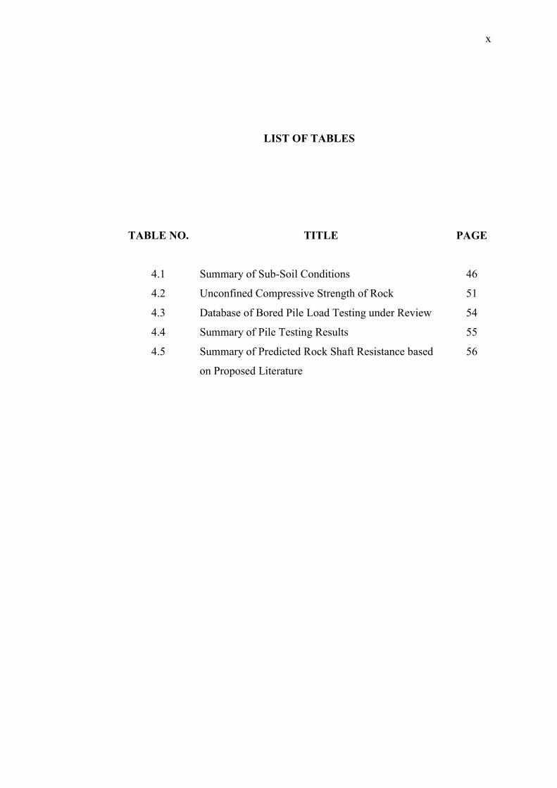
LIST OF TABLES
TABLE NO. TITLE PAGE
4.1 Summary of Sub-Soil Conditions 46
4.2 Unconfined Compressive Strength of Rock 51
4.3 Database of Bored Pile Load Testing under Review 54
4.4 Summary of Pile Testing Results 55
4.5 Summary of Predicted Rock Shaft Resistance based
on Proposed Literature
56

xi
LIST OF FIGURES
FIGURE NO. TITLE PAGE
1.1 Key Plan and Location Map 2
1.2 Proposed MRT Alignment (Sungai Buloh to
Kajang)
3
2.1 Rock Socket Reduction Factor, (After Tomlinson,
1995)
22
2.2 Rock Socket Reduction Factor, (After Tomlinson,
1995)
22
2.3 Maintained Load Test Setup 27
2.4 (a) Test Equipments : 30 tonne steel ram with hydraulic
releaser
32
2.4 (b) Test Equipments : Pile Driving Analyser 32
2.4 (c) Test Equipments : accelerometer 32
2.4 (d) Test Equipments: transducer 32
3.1 Methodology Framework of The Study 37
4.1 Geological Map of Proposed MRT Alignment 43
4.2 (a) Sub-soil Profile Along Boreholes BH-TP3 to BH7-
IPLT
47
4.2 (b) Sub-soil Profile Along Boreholes BH-10 to BH-18 48
4.2 (c) Sub-soil Profile Along Boreholes BH-21 to BH-11s 49
4.3 Maximum Mobilised Rock Shaft Resistance versus
UCS
58

xi
4.4 Maximum Mobilised Rock Shaft Resistance versus
Pile Top Settlement
58
4.5 (a) Measured versus Predicted for Rock Shaft
Resistances : Rowe & Armitage (1987)
59
4.5 (b) Measured versus Predicted for Rock Shaft
Resistances : Rosenberg & Journeaux (1976),
59
4.5 (c) Measured versus Predicted for Rock Shaft
Resistances : Horvath & Kenney, b=0.2 (1979)
60
4.5 (d) Measured versus Predicted for Rock Shaft
Resistances : Horvath & Kenney, b=0.3 (1979),
60
4.5 (e) Measured versus Predicted for Rock Shaft
Resistances : Zhang & Einstein (1998)
61
4.6 Maximum Rock Shaft Resistance versus RQD 62
4.7 Unconfined Compressive Strength of Rock versus
RQD
63

xiii
LIST OF SYMBOLS
Qag - Allowable geotechnical capacity
Qsu - Ultimate shaft capacity
Qbu - Ultimate base capacity
fsu - Unit shaft resistance for each layer
fbu - Unit base resistance for the bearing layer
As - Pile shaft area
Ab - Pile base area
Fs - Partial Factor of Safety for Shaft Resistance
Fb - Partial Factor of Safety for Base Resistance
Fg - Global Factor of Safety for Total Resistance
Ksu - Ultimate unit shaft resistance of soil
Kbu - Ultimate unit bearing resistance of soil
- Adhesion factor
su - Undrained shear strength
Kse - Effective stress shaft resistance factor
v - Vertical effective stress
' - Effective angle of friction (degree) of soils
Nc - Bearing capacity factor
- Shaft resistance factor for coarse grained soils
quc - Unconfined compressive strength of intact rock
- Reduction factor with respect to quc
- Reduction factor with respect to the rock mass effect
qs - Ultimate rock shaft resistance
xiii
uc - Unconfined compressive strength of intact rock
rc - Unconfined compressive strength of rock or concrete
jc - Case method damping factor
ε - Strain
Ru - Ultimate resistance in the soil ‘springs’
qs(max) - Maximum mobilised rock shaft resistance
CHAPTER 1
INTRODUCTION
1.1 Background
The Klang Valley Mass Rapid Transit (KVMRT) is the latest rail-based
public transport development and being constructed by Government of Malaysia to
alleviate the traffic congestion in Kuala Lumpur. This first phase of this project
involves the construction of 51km rail alignment from Sungai Buloh to Kajang.
Locations of the KVMRT project are shown in Figure 1.1 and Figure 1.2. As initially
envisaged the project required the construction of thousands of large diameter bored
piles from 1m diameter and up to 2.8m diameter to support both the viaducts and
station developments. These structures were to be founded on a wide range of rock
types comprising the geological of granite, kenny hill, limestone and kajang
formations.
Deep foundations are a common foundation selection for all types of
structures particularly cast in-situ bored pile. Bored pile was chosen in the
advantages of minimum ground vibration, higher design working load, and can be
installed into rock bearing strata. It is becoming common practice to socket the shafts
into bedrock to transmit high foundation loads. However, the need to improve the

2
efficiency of pile designs and higher design loads is providing an increasing
requirement for rock-socketed piles. Design loads are limited for piles relying upon
end bearing in rock, even if the measured rock strength is higher than the pile
concrete strength. This is due to uncertainty about the rock quality over whole pile
diameter, which may be lower than expected because of weathering or construction
effects. Thus, it is prudent to design an optimum rock shaft resistance in order to
prevent excessive rock socketing.
Figure 1.1 : Key Plan and Location Map
N N

3
Figure 1.2 : Proposed MRT Alignment (Sungai Buloh to Kajang)
Due to the uncertainties associated with pile design, available semi-empirical/
empirical methods for determination of ultimate resistance of pile may pose
unreliability and, thereby, may significantly affect safety and economy of a project.
Therefore, although expensive, pile load tests are usually conducted to verify the
design loads and to evaluate the actual response of the pile under loading.
Static load tests (SLT) are generally a “must” and are among the most reliable
and important to ensure satisfactory pile performance with particular reference to the
capacity, settlement and structural integrity. Usually, at least one or two tests per site
or 1 to 2% of the piles are selected for load tests. During this test, load would be
applied on the selected pile and the pile settlement under the acting load would be
recorded. As a common practice, pile would be loaded up to twice of the working
load, which is regarded as the Test Load of the pile. On most occasions, the results of
this test do not show a distinct plunging ultimate load, therefore the results need
interpretation to estimate pile capacity or ultimate load.
4
1.2 Problem Statement
It is noticeable that very few studies on the ultimate rock shaft resistance of
bored piles particularly on igneous rock have been carried out in Malaysia. Most of
the bored piles design Malaysia is practised in based on the proposed literatures
which were emphasized on sedimentary rocks. The method used by previous
literatures correlates the maximum rock shaft resistance with respect to rock
compressive strength which is obtained from laboratory test results conducted on the
intact rock core samples.
Design methods based on the performance of sockets in sedimentary rocks
have been proposed in the literatures, but it is uncertain how applicable these
methods to other rock types. The problem faced by designers is what magnitude of
skin friction can be shed into the granite in Malaysia. Whether the characteristics of
this type of rock are similar with granite in other countries like Hong Kong.
1.3 Objective of the Study
The aim of this study is to identify the most appropriate interpretation
methods to estimate the rock shaft resistance of granite in Malaysia. The objective of
the study comprises of the following:
(i) To review the applicability of available design relationship addressing shaft
resistance of decomposed rock.
(ii) To determine the maximum rock shaft resistance particularly in granite
formation in Malaysia.
(iii) To validate the designs relationship with respect to field pile load test results.
5
(iv) To identify the trends in behaviour of rock discontinuities and unconfined
compressive strength with respect to maximum rock shaft resistance.
1.4 Scope of the Study
This study is based on the real time construction project of the proposed
Klang Valley MRT Jajaran Sungai Buloh to Kajang. It is worth to note that there are
thousands of bored piles have been proposed for foundation supports to the MRT
viaducts and station developments. These bored piles are to be founded in wide
range of rock types comprised on granite, kenny hill, limestone and kajang
formations. However for this study, only the rock shaft resistance of bored piles with
diameter varying from 1000mm to 1500mm which were constructed in granite
formation have been considered. All of these bored piles were socketed from 1m up
to 7.3m into rock and tested with pile load testing.
The scope of this study is on the prediction of socket shaft resistance rather
than end bearing resistance. The data for this study was acquired from MMC-
Gamuda KVMRT (PDP) Sdn Bhd. These include Soil Investigation Reports, bored
piling records and pile load testing results. In total, 15 pile testing results which
consists of 5 using static load test and 10 using dynamic load test were reviewed and
evaluated.

6
1.5 Significance of the Study
The precise prediction of maximum rock shaft resistance of bored piles in
granite is a complex problem because it is function of a numbers of factors. These
factors include method of boring and coring, rock discontinuities, surface roughness,
method of concreting, quality of concrete, expertise of the construction personnel,
ground conditions etc. beside the pile geometry. Typically, the ultimate values of
rock shaft resistance adopted in bored pile design for granite formation in Malaysia is
limited between 1000 kPa to 1400 kPa subject to the rock compressive strength
results whichever is the lowest.
The significance of this study is to ensure the design methods adopted for
design of rock shaft resistance are satisfactory and in order. This study will also
provides more understanding on the trends of rock discontinuities particularly of
RQD and rock compressive strength with respect to maximum rock shaft resistances.
Eventually, magnitude of ultimate rock shaft resistance for granite formation can be
determined which can be adopted in the bored pile design.
REFERENCES
Buildings Ordinance Office (BOO). (1980). “Pile foundations.” Prac. Note for
Authorised Persons and Registered Struct. Engrs., No. 66, 1997 Revision,
Buildings Department, Hong Kong.
Briaud, J., Ballouz, M., and Nasr, G. (2000). “Static Capacity Prediction by Dynamic
Methods for Three Bored Piles.” J. Geotech. Geoenviron. Eng., 126(7), 640–649.
Bastidas, V. and Caicedo, N. (2011). “High-Strain Dynamic Load Testing at the
Bahia-San Vicente Bridge: Evaluation of Results against Design Values”. Geo-
Frontiers 2011: pp. 20-26.
Charles W. W. Ng, Terence L.Y.Yau, and Jonathan H.M.Li (2001). “Side resistance
of large diameter bored piles socketed into decomposed rocks.”. Journal of
Geotechnical and Geoenvirontmental Engineering: Vol. 127, No. 8, August 2001,
pp. 658-669.
Coduto, Donald P., (1994). Foundation Design: Principles and Practices. Prentice
Hall, United States of America.
Garland Likins, Frank Rausche (2004). Correlation of CAPWAP with Static Load
Test. Proceedings of The Seventh International Conference on the Application of
Stresswave Theory to Piles 2004, The Institute of Engineers Malaysia.
69
Hong Kong Special Administrative Region. (2004)."Code of Practice for
Foundation"., Buildings Department, Hong Kong
Hong Kong Special Administrative Region. (2006)."Foundation Design and
Construction"., Geo-Publication No.1/2006, Civil Engineering and Development
Department, Hong Kong
Horvath, R. G. (1978). “Field load test data on concrete-to-rock bond strength for
drilled pier foundations.”Publ. 78/07, Dept. of Civ. Engrg., University of Toronto,
Toronto
Horvath, R. G., and Kenney, T. C. (1979). “Shaft resistance of rock socketed drilled
piers.” Proc., Symp. on Deep Found., ASCE, New York, 18Hussein, M.,
Robinson, B., and Likins, G. (2004). “Applications of a Simplified Dynamic Load
Testing Method for Cast-in-Place Piles”, PROCEEDINGS GeoSupport 2004:
Drilled Shafts, Micropiling, Deep Mixing, Remedial Methods, and Specialty
Foundation Systems, GeoSupport 2004: pp. 110-121.
International Society for Rock Mechanics (ISRM). (1985). “Suggested method for
determining point load strength.” Int. J. Rock Mech. and Mining Sci., 22, 51–60.
Pells, P. J. N., Douglas, D. J., Rodway, B., Thorne, C., and McManhon, B. K.
(1978). “Design loadings for foundations on shale and sandstone in the Sydney
region.” Res. Rep. No. R315, University of Sydney, Sydney, Australia.
Poulos H.G. and Davis E.H. (1980). Pile Foundation Analysis and Design.Wiley &
Sons, New York. (reprinted by Krieger Publishing, Malabar, Florida, 1990)
Reese, LC. & O’Neill, M.W. (1988).Drilled Shaft : Construction Procedures and
Design Methods, US Department of Transportation-Federal Highway
Administration (Office of Implementation, Washington)
Rosenberg, P., and Journeaux, N. L. (1976). “Friction and end bearing tests on
bedrock for high capacity socket design.” Can. Geotech. J.,Ottawa, 13, 324–333

70
Rowe, R. K., and Armitage, H. H. (1987b). “A design method for drilled piers in soft
rock.”Can. Geotech. J., Ottawa, 24, 126–142.
Svinkin, M. (2011). “Engineering Aspects in Evaluation of Pile Capacity by
Dynamic Testing”. Structures Congress 2011: pp. 1686-1697.
Tomlinson, M. J. (1996). Pile design and construction practice, E&FN Spon,
Chapman & Hall, London.
Tan, Y.C., Chen, C.S. & Liew, S.S. (1998) Load Transfer Behaviour of Cast-in place
Bored Piles in Tropical Residuals Soils. roceedings of the 13th Southeast Asian
Geotechnical Conferences, Taipei
Toh C.T., Ooi T.A., Chiu H.K., Chee S.K., and Ting W.H. (1989). Design
Parameters for bored piles in a weathered sedimentary formation. Proceeding of
the 12thInternational Conference on Soil Mechanics and Foundation Engineering,
Rio de Janeiro, Vol 2