roc800l flow calculations user manual - spartan controls/media/resources/roc/roc800l... · the...
TRANSCRIPT

Remote Automation Solutions
Part Number D301688X012 Form Number A6311 March 2016
ROC800L Flow Calculations User Manual
ROC800L Flow Calculations User Manual
ii Issued March-2016
Revision Tracking Sheet March 2016
This manual may be revised periodically to incorporate new or updated information. The revision date of each page appears at the bottom of the page opposite the page number. A change in revision date to any page also changes the date of the manual that appears on the front cover. Listed below is the revision date of each page (if applicable):
Page Revision Initial release March-2016

ROC800L Flow Calculations User Manual
Issued March-2016 Contents iii
Contents Chapter 1 – Overview 1
1.1 Scope of Manual ................................................................................................................................ 1
Chapter 2 – Calculation of Densities and Volume Correction Factors 3
2.1 Observed to Base Calculations .......................................................................................................... 3 2.1.1 CTL (observed to base) ....................................................................................................... 4 2.1.2 Compressibility (F) (observed to base) ................................................................................ 5 2.1.3 CPL (observed to base) ....................................................................................................... 5 2.1.4 CTPL (observed to base) ..................................................................................................... 6 2.1.5 Base Density ........................................................................................................................ 6
2.2 Base to Alternate Calculations ........................................................................................................... 6 2.2.1 Coefficient of Thermal Expansion (Alpha) ........................................................................... 7 2.2.2 CTL (base to alternate) ........................................................................................................ 7 2.2.3 Compressibility (F) (base to alternate) ................................................................................. 8 2.2.4 CPL (base to alternate) ........................................................................................................ 8 2.2.5 CTPL (base to alternate) ...................................................................................................... 8 2.2.6 Meter Density ....................................................................................................................... 9 2.2.7 CSW ..................................................................................................................................... 9
Chapter 3 – Calculation of Quantity Totals 11
3.1 Pulse Totals ...................................................................................................................................... 11 3.2 Indicated Quantity Totals ................................................................................................................. 12 3.3 Gross Volume Totals ........................................................................................................................ 12 3.4 Gross Standard Volume Totals ........................................................................................................ 13 3.5 Net Standard Volume Totals ............................................................................................................ 14 3.6 Sediment and Water Volume Totals ................................................................................................ 15 3.7 Mass Totals ...................................................................................................................................... 16
Chapter 4 – Calculation of Meter Averages 19
4.1 Flow-Weighted Averages ................................................................................................................. 19 4.2 Flow Rate Averages ......................................................................................................................... 20
Chapter 5 – Calculations of Batch Averages and Totals 21
5.1 Opening and Closing Meter Readings ............................................................................................. 21 5.2 Indicated Volume Totals ................................................................................................................... 21 5.3 Gross Volume Totals ........................................................................................................................ 22 5.4 Gross Standard Volume Totals ........................................................................................................ 22 5.5 Net Standard Volume Totals ............................................................................................................ 22 5.6 Sediment and Water Volume Totals ................................................................................................ 23 5.7 Mass Totals ...................................................................................................................................... 23 5.8 Flow-Weighted Temperature Average ............................................................................................. 24 5.9 Flow-Weighted Pressure Average ................................................................................................... 24 5.10 Flow-Weighted Density Average ...................................................................................................... 25 5.11 Flow Weighted Correction Factor Average ...................................................................................... 25

ROC800L Flow Calculations User Manual
iv Contents Issued March-2016
Chapter 6 – Calculation of Meter Factor using Volume Displacement Proving 27
6.1 Calculation of Gross Standard Prover Volume (GSVp) ................................................................... 27 6.1.1 Calculation of Correction for Temperature on the Prover Body......................................... 28 6.1.2 Calculation of Correction for Pressure on the Prover Body ............................................... 29
6.2 Calculation of the Volume of the Liquid through the Meter at Base Conditions (ISVm) .................. 29 6.3 Calculation of Meter Factor and Repeatability using Average Meter Factor Method ...................... 30
6.3.1 Calculation of Trial Run Meter Factor ................................................................................ 30 6.3.2 Average Trial Run Pressure .............................................................................................. 31 6.3.3 Average Trial Run Temperature ........................................................................................ 32 6.3.4 Repeatability Calculation ................................................................................................... 32 6.3.5 Final Meter Factor Calculation ........................................................................................... 32
6.4 Calculation of Meter Factor and Repeatability using Average Data Method ................................... 33 6.4.1 Repeatability Calculation ................................................................................................... 33 6.4.2 Average Pulse Calculation ................................................................................................. 33 6.4.3 Average Pressure Calculation ........................................................................................... 34 6.4.4 Average Temperature Calculation ..................................................................................... 34 6.4.5 Meter Factor Calculation .................................................................................................... 34

ROC800L Flow Calculations User Manual
Issued March-2016 Overview 1
Chapter 1 – Overview
This document describes the ROC800L calculations for density, volume correction factors, quantity totals, meter averages, batch averages and totals, and meter factor using volume displacement proving.
Note: Information contained in this document does not cover all described calculations in the ROC800L.
1.1 Scope of Manual This manual contains the following chapters: Chapter 1 Overview
A brief description of ROC800L flow calculations.
Chapter 2 Calculation of Densities and Volume Correction Factors
This chapter describes the methods to calculate base density, meter density, and correction factors used to correct the measured volume to a net standard volume of hydrocarbon fluid as described in API Chapter 11.1 (2004).
Chapter 3 Calculation of Quantity Totals
This chapter describes the methods to calculate the hourly, daily averages for meter inputs and calculated values.
Chapter 4 Calculation of Meter Averages
This chapter describes the methods to calculate the hourly, daily averages for meter inputs and calculated values.
Chapter 5 Calculation of Batch Averages and Totals
This chapter describes the calculation and rounding methods to calculate the flow weighted averages and quantity totals over a batch.
Chapter 6 Calculation of Averages and Totals for Batch Tickets
This chapter describes the calculation and rounding methods to calculate a meter factor from a successful prove for both the average data method and the average meter factor method, including rounding.

ROC800L Flow Calculations User Manual
2 Overview Issued March-2016
[This page is intentionally left blank.]

ROC800L Flow Calculations User Manual
Issued March-2016 Calculation of Densities and Volume Correction Factors 3
Chapter 2 – Calculation of Densities and Volume Correction Factors
In This Chapter
2.1 Observed to Base Calculations .......................................................... 3 2.1.1 CTL (observed to base) ........................................................... 4 2.1.2 Compressibility (F) (observed to base) ................................... 5 2.1.3 CPL (observed to base) .......................................................... 5 2.1.4 CTPL (observed to base) ........................................................ 6 2.1.5 Base Density ........................................................................... 6
2.2 Base to Alternate Calculations ............................................................ 6 2.2.1 Coefficient of Thermal Expansion (Alpha) ............................... 7 2.2.2 CTL (base to alternate) ........................................................... 7 2.2.3 Compressibility (F) (base to alternate) .................................... 8 2.2.4 CPL (base to alternate) ........................................................... 8 2.2.5 CTPL (base to alternate) ......................................................... 8 2.2.6 Meter Density .......................................................................... 9 2.2.7 CSW ........................................................................................ 9
This chapter describes the methods to calculate base density, meter density, and correction factors used to correct the measured volume to a net standard volume of hydrocarbon fluid as described in API Chapter 11.1 (2004).
2.1 Observed to Base Calculations This section describes the methods to calculate a base density (density at base temperature and atmospheric pressure) from an observed density (density at an observed temperature and pressure). The observed density input and associated observed temperature and pressure must come in to the ROC800L through one of the density interface points which is assigned either to a station or to a meter. If the density interface point is assigned to a station, the base density is calculated at the station and used by all the meters that are part of the station. If the density interface point is assigned to a meter, the base density is calculated and used at that meter only.
The observed to base correction factors are stored as shown in Table 2-1.
Table 2-1. Observed to Base Correction Factors (Base) Description TLP Factor Correction for Temperature of the Liquid from Observed to Base (CTLobsbase) 204,x,48 Not rounded
Correction for Pressure of the Liquid from Observed to Base (CPLobsbase) 204,x,49 Not rounded
Correction for Temp and Press of the Liquid from Observed to Base (CTPLobsbase) 204,x,42 Not rounded
Compressibility Factor of the Liquid from Observed to Base (Fobsbase) 204,x,51 Not rounded
Thermal Expansion Factor of the Liquid at Base Conditions (Alpha) 204,x,41 Not rounded

ROC800L Flow Calculations User Manual
4 Calculation of Densities and Volume Correction Factors Issued March-2016
Description TLP Factor Density of the Liquid at Base Conditions (RHObase) 204,x,23 Not rounded
2.1.1 CTL (observed to base) The calculation of the temperature correction factor for observed densitometer conditions to base conditions detailed below is performed in accordance with API Manual of Petroleum Measurement Standards (Chapter 11.1, 2004). The correction factors are calculated for a base of 15°C and 0 kPa(g). However, because the CTPL expressions were developed and expressed in terms of a base density at 60°F, this calculation must be done using the following steps:
1. Convert the observed temperature and base temperature from °C to °F and convert the observed pressure in kPa(g) to PSIG (see equations below – reference API section 11.1.5.1).
2. Convert the temperature at ITS-90 to IPTS-68 (reference API section 11.1.5.3) using the following formula.
3. Calculate density at 60°F (RHO60) and associated correction factors (CTL, CPL, CTPL, Fp) for observed 60°F (see equations below - reference API section 11.1.6.2).
4. Using this value of RHO60, calculate density at 15°C and associated temperature correction factor (CTL) 60°F15°C (see equations below – reference 11.1.6.1).
5. Using this value of RHO60, calculate density at line conditions and associated correction factors (CTL, CPL, CTPL, F) for 60°Fline (see equations below – reference 11.1.6.1).
6. Calculate the CTL for observed temperature to 15°C using:
CTL(obs15°C) = CTL (obs60°F) / CTL (60°F15°C)
The calculation for the effect of temperature on the liquid is: ( )[ ]{ }606060 8.01exp δαα +∆+∆−= ttCTL
Where: CTL = Correction factor for the effect of temperature on the
liquid α60 = Coefficient of thermal expansion of the liquid (°F-1) Δt = t* - 60.0068749 t* = Temperature of the liquid at the meter (°F) δ60 = Temperature shift value (a constant 0.01374979547 °F)
ROC800L Flow Calculations User Manual
Issued March-2016 Calculation of Densities and Volume Correction Factors 5
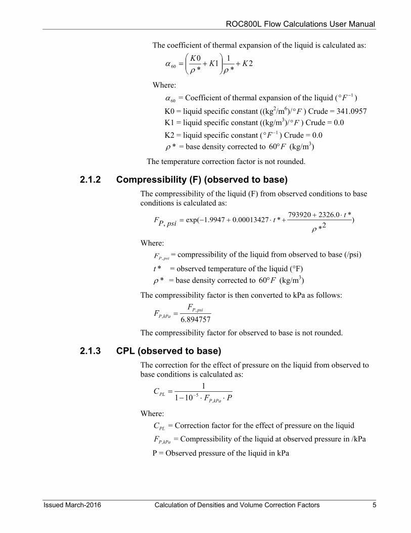
The coefficient of thermal expansion of the liquid is calculated as:
2*
11*0
60 KKK+
+=
ρρα
Where:
60α = Coefficient of thermal expansion of the liquid ( 1−°F )
K0 = liquid specific constant ((kg2/m6)/ F° ) Crude = 341.0957 K1 = liquid specific constant ((kg/m3)/ F° ) Crude = 0.0 K2 = liquid specific constant ( 1−°F ) Crude = 0.0
*ρ = base density corrected to F°60 (kg/m3)
The temperature correction factor is not rounded.
2.1.2 Compressibility (F) (observed to base) The compressibility of the liquid (F) from observed conditions to base conditions is calculated as:
)2*
*0.2326793920*00013427.09947.1exp(,
ρ
ttpsiPF
⋅++⋅+−=
Where:
psiPF ,= compressibility of the liquid from observed to base (/psi)
*t = observed temperature of the liquid (°F) *ρ = base density corrected to F°60 (kg/m3)
The compressibility factor is then converted to kPa as follows:
894757.6,
,psiP
kPaP
FF =
The compressibility factor for observed to base is not rounded.
2.1.3 CPL (observed to base) The correction for the effect of pressure on the liquid from observed to base conditions is calculated as:
PFC
kPaPPL ⋅⋅−= −
,5101
1
Where:
PLC = Correction factor for the effect of pressure on the liquid
kPaPF , = Compressibility of the liquid at observed pressure in /kPa
P = Observed pressure of the liquid in kPa
ROC800L Flow Calculations User Manual
6 Calculation of Densities and Volume Correction Factors Issued March-2016
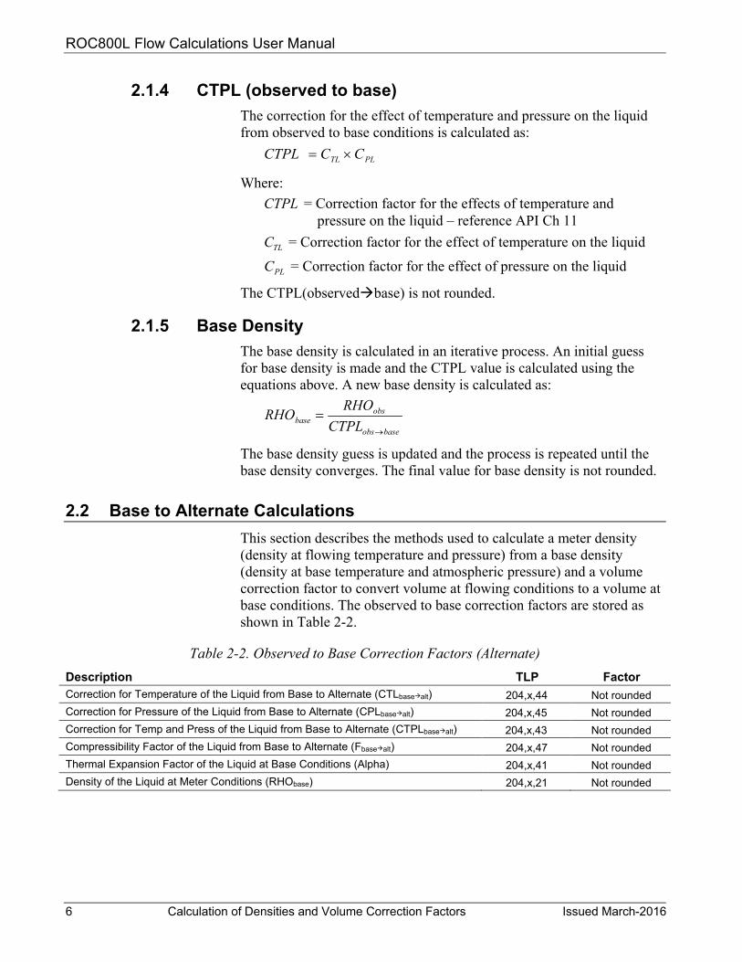
2.1.4 CTPL (observed to base) The correction for the effect of temperature and pressure on the liquid from observed to base conditions is calculated as:
PLTL CCCTPL ×=
Where: CTPL = Correction factor for the effects of temperature and
pressure on the liquid – reference API Ch 11
TLC = Correction factor for the effect of temperature on the liquid
PLC = Correction factor for the effect of pressure on the liquid
The CTPL(observedbase) is not rounded.
2.1.5 Base Density The base density is calculated in an iterative process. An initial guess for base density is made and the CTPL value is calculated using the equations above. A new base density is calculated as:
baseobs
obsbase CTPL
RHORHO→
=
The base density guess is updated and the process is repeated until the base density converges. The final value for base density is not rounded.
2.2 Base to Alternate Calculations This section describes the methods used to calculate a meter density (density at flowing temperature and pressure) from a base density (density at base temperature and atmospheric pressure) and a volume correction factor to convert volume at flowing conditions to a volume at base conditions. The observed to base correction factors are stored as shown in Table 2-2.
Table 2-2. Observed to Base Correction Factors (Alternate) Description TLP Factor Correction for Temperature of the Liquid from Base to Alternate (CTLbasealt) 204,x,44 Not rounded Correction for Pressure of the Liquid from Base to Alternate (CPLbasealt) 204,x,45 Not rounded Correction for Temp and Press of the Liquid from Base to Alternate (CTPLbasealt) 204,x,43 Not rounded Compressibility Factor of the Liquid from Base to Alternate (Fbasealt) 204,x,47 Not rounded Thermal Expansion Factor of the Liquid at Base Conditions (Alpha) 204,x,41 Not rounded Density of the Liquid at Meter Conditions (RHObase) 204,x,21 Not rounded

ROC800L Flow Calculations User Manual
Issued March-2016 Calculation of Densities and Volume Correction Factors 7
2.2.1 Coefficient of Thermal Expansion (Alpha) The coefficient of thermal expansion of the liquid is calculated as:
2*
11*0
60 KKK+
+=
ρρα
Where:
60α = Coefficient of thermal expansion of the liquid ( 1−°F )
K0 = liquid specific constant ((kg2/m6)/ F° ) Crude = 341.0957 K1 = liquid specific constant ((kg/m3)/ F° ) Crude = 0.0
K2 = liquid specific constant ( 1−°F ) Crude = 0.0 *ρ = base density corrected to F°60 (kg/m3)
2.2.2 CTL (base to alternate) The calculation of the volume correction factors for base to line conditions detailed below are performed in accordance with API Manual of Petroleum Measurement Standards (Chapter 11.1, 2004). The correction factors are calculated from a base of 15°C and 0 barg. However, because the VCF expressions were developed and expressed in terms of a base density at 60°F, this calculation must be done using the following steps:
1. Convert the meter temperature and base temperature from °C to °F and convert the meter pressure in barg to PSIG (reference API section 11.1.5.1).
2. Convert the temperature at ITS-90 to IPTS-68 (reference API section 11.1.5.3).
3. Calculate density at 60°F (RHO60) and associated correction factor (CTL) for 15°C60°F (reference API section 11.1.6.2).
4. Using this value of RHO60, calculate density at line temperature pressure and associated correction factors (CTL, CPL, CTPL, Fp) 60°Fline (reference 11.1.6.1).
5. Calculate the CTL for 15°C to line temperature using: CTL(15°Cline) = CTL (60°Fline) / CTL (15°C60°F)
The correction for the effect of temperature on the liquid is calculated as:
( )[ ]{ }606060 8.01exp δαα +∆+∆−= ttCTL Where:
CTL = Correction factor for the effect of temperature on the liquid
60α = Coefficient of thermal expansion of the liquid ( 1−°F )
ROC800L Flow Calculations User Manual
8 Calculation of Densities and Volume Correction Factors Issued March-2016
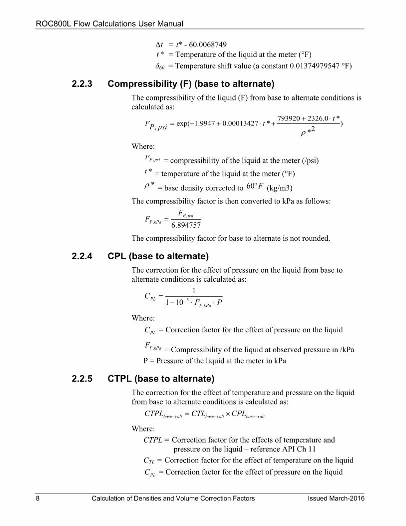
Δt = t* - 60.0068749 *t = Temperature of the liquid at the meter (°F) δ60 = Temperature shift value (a constant 0.01374979547 °F)
2.2.3 Compressibility (F) (base to alternate) The compressibility of the liquid (F) from base to alternate conditions is calculated as:
)2*
*0.2326793920*00013427.09947.1exp(,
ρ
ttpsiPF
⋅++⋅+−=
Where:
psiPF , = compressibility of the liquid at the meter (/psi) *t = temperature of the liquid at the meter (°F) *ρ = base density corrected to F°60 (kg/m3)
The compressibility factor is then converted to kPa as follows:
894757.6,
,psiP
kPaP
FF =
The compressibility factor for base to alternate is not rounded.
2.2.4 CPL (base to alternate) The correction for the effect of pressure on the liquid from base to alternate conditions is calculated as:
PFC
kPaPPL ⋅⋅−= −
,5101
1
Where:
PLC = Correction factor for the effect of pressure on the liquid
kPaPF , = Compressibility of the liquid at observed pressure in /kPa P = Pressure of the liquid at the meter in kPa
2.2.5 CTPL (base to alternate) The correction for the effect of temperature and pressure on the liquid from base to alternate conditions is calculated as:
altbasealtbasealtbase CPLCTLCTPL →→→ ×=
Where: CTPL = Correction factor for the effects of temperature and
pressure on the liquid – reference API Ch 11 CTL = Correction factor for the effect of temperature on the liquid
PLC = Correction factor for the effect of pressure on the liquid
ROC800L Flow Calculations User Manual
Issued March-2016 Calculation of Densities and Volume Correction Factors 9
The CTPL(basealternate) is rounded to 5 decimal places.
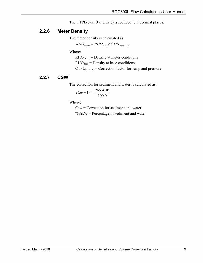
2.2.6 Meter Density The meter density is calculated as:
altbasebasemeter CTPLRHORHO →×=
Where: RHOmeter = Density at meter conditions RHObase = Density at base conditions CTPLbasealt = Correction factor for temp and pressure
2.2.7 CSW The correction for sediment and water is calculated as:
0.100&%0.1 WSCsw −=
Where:
Csw = Correction for sediment and water %S&W = Percentage of sediment and water

ROC800L Flow Calculations User Manual
10 Calculation of Densities and Volume Correction Factors Issued March-2016
[This page is intentionally left blank.]

ROC800L Flow Calculations User Manual
Issued March-2016 Calculation of Quantity Totals 11
Chapter 3 – Calculation of Quantity Totals
In This Chapter
3.1 Pulse Totals ...................................................................................... 11 3.2 Indicated Quantity Totals .................................................................. 12 3.3 Gross Volume Totals ........................................................................ 12 3.4 Gross Standard Volume Totals ......................................................... 13 3.5 Net Standard Volume Totals ............................................................. 14 3.6 Sediment and Water Volume Totals ................................................. 15 3.7 Mass Totals ....................................................................................... 16
This chapter describes the methods to calculate the hourly, daily, and monthly totals, and averages as well as the non-resettable totals that are not part of a batch. The daily totals rollover at the contract hour defined on the Liquid Preferences display and the monthly totals rollover on the first day of the month at contract hour. Non-resettable totals will rollover at the value defined for all double precision accumulators in the ROC system information (91,0,56). By default, this value is 1,000,000,000,000.
3.1 Pulse Totals The pulse totals are kept for each meter for current hour, previous hour, current day, previous day, current month, and previous month as well as a non-resettable pulse total. The incremental pulse count for each calculation period is calculated as:
eviousCurrentincr AccumAccumPulse Pr−= Where:
PulseIncr = Incremental pulses for the calculation period AccumCurrent = PI or APM accumulator at the time of the
calculation AccumPrevious = PI or APM accumulator at the time of the previous
calculation Each pulse accumulator is then incremented by the incremental pulses for the calculation period. Pulse totals are not available at the station level. The values are stored as shown in Table 3-1.
Table 3-1. Pulse Total TLP Description TLP Factor Meter Non-resettable Pulse Total 204,x,184 Not rounded Meter Current Hour Pulse Total 204,x,178 Not rounded Meter Previous Hour Pulse Total 204,x,179 Not rounded Meter Current Day Pulse Total 204,x,180 Not rounded Meter Previous Day Pulse Total 204,x,181 Not rounded Meter Current Month Pulse Total 204,x,182 Not rounded Meter Previous Month Pulse Total 204,x,182 Not rounded

ROC800L Flow Calculations User Manual
12 Calculation of Quantity Totals Issued March-2016
3.2 Indicated Quantity Totals The indicated quantity totals are kept for each meter and for each station for the current hour, previous hour, current day, previous day, current month, and previous month as well as a non-resettable total. The indicated quantity may represent volume or mass, depending on the flow meter type selection at the meter. The incremental indicated quantity for each calculation period is calculated as:
KfactorPulse
IV incrincr =
Where:
IVincr = Incremental indicated quantity for the calculation period Pulseincr = Incremental pulses for the calculation period K-factor = Pulses / Volume or Pulses / Mass
Each meter indicated quantity accumulator is incremented by the incremental IV for the calculation period. Each station indicated quantity accumulator is incremented by the incremental IV for the calculation period for all the meters that are part of that station. The values are stored as shown in Table 3-2.
Table 3-2. Indicated Quantity Total TLP Description TLP Factor Meter Non-resettable IV Total 204,x,145 Not rounded Meter Current Hour IV Total 204,x,109 Not rounded Meter Previous Hour IV Total 204,x,115 Not rounded Meter Current Day IV Total 204,x,121 Not rounded Meter Previous Day IV Total 204,x,127 Not rounded Meter Current Month IV Total 204,x,133 Not rounded Meter Previous Month IV Total 204,x,139 Not rounded Station Non-resettable IV Total 203,x,71 Not rounded Station Current Hour IV Total 203,x,35 Not rounded Station Previous Hour IV Total 203,x,41 Not rounded Station Current Day IV Total 203,x,47 Not rounded Station Previous Day IV Total 203,x,53 Not rounded Station Current Month IV Total 203,x,59 Not rounded Station Previous Month IV Total 203,x,65 Not rounded
3.3 Gross Volume Totals The gross volume totals are kept for each meter and for each station for the current hour, previous hour, current day, previous day, current month, and previous month as well as a non-resettable total.
If the indicated quantity represents volume, the incremental gross volume quantity for each calculation period is calculated as:
MFIVGV incrincr ×=

ROC800L Flow Calculations User Manual
Issued March-2016 Calculation of Quantity Totals 13
If the indicated quantity represents mass, the incremental gross volume quantity for each calculation period is calculated as:
meter
incrincr RHO
MFIVGV
×=
Where:
GVincr = Incremental gross volume for the calculation period IVincr = Incremental indicated quantity for the calculation period RHOmeter = Density of the liquid at meter conditions MF = Meter Factor
Each meter gross volume accumulator is incremented by the incremental GV for the calculation period. Each station gross volume accumulator is incremented by the incremental GV for the calculation period for all the meters that are part of that station. The values are stored as shown in Table 3-3.
Table 3-3. Gross Volume Total TLP Description TLP Factor Meter Non-resettable GV Total 204,x,146 Not rounded
Meter Current Hour GV Total 204,x,110 Not rounded
Meter Previous Hour GV Total 204,x,116 Not rounded
Meter Current Day GV Total 204,x,122 Not rounded
Meter Previous Day GV Total 204,x,128 Not rounded
Meter Current Month GV Total 204,x,134 Not rounded
Meter Previous Month GV Total 204,x,140 Not rounded
Station Non-resettable GV Total 203,x,72 Not rounded
Station Current Hour GV Total 203,x,36 Not rounded
Station Previous Hour GV Total 203,x,42 Not rounded
Station Current Day GV Total 203,x,48 Not rounded
Station Previous Day GV Total 203,x,54 Not rounded
Station Current Month GV Total 203,x,60 Not rounded
Station Previous Month GV Total 203,x,66 Not rounded
3.4 Gross Standard Volume Totals The gross standard volume totals are kept for each meter and for each station for the current hour, previous hour, current day, previous day, current month, and previous month as well as a non-resettable total.
If the indicated quantity represents volume, the incremental gross standard volume quantity for each calculation period is calculated as:
mincrincr CCFIVGSV ×= If the indicated quantity represents mass, the incremental gross standard volume quantity for each calculation period is calculated as:
altbaseincrincr CTPLGVGSV →×=

ROC800L Flow Calculations User Manual
14 Calculation of Quantity Totals Issued March-2016
Where: GSVincr = Incremental gross standard volume for the calculation
period GVincr = Incremental gross volume for the calculation period IVincr = Incremental indicated quantity for the calculation period CCFm = Combined correction factor for the meter CTPLbase->alt = Correction for temp and pressure base to alternate
conditions
Each meter gross standard volume accumulator is incremented by the incremental GSV for the calculation period. Each station gross standard volume accumulator is incremented by the incremental GSV for the calculation period for all the meters that are part of that station. The values are stored as shown in Table 3-4.
Table 3-4. Gross Standard Volume Total TLP Description TLP Factor Meter Non-resettable GSV Total 204,x,147 Not rounded Meter Current Hour GSV Total 204,x,111 Not rounded Meter Previous Hour GSV Total 204,x,117 Not rounded Meter Current Day GSV Total 204,x,123 Not rounded Meter Previous Day GSV Total 204,x,129 Not rounded Meter Current Month GSV Total 204,x,135 Not rounded Meter Previous Month GSV Total 204,x,141 Not rounded Station Non-resettable GSV Total 203,x,73 Not rounded Station Current Hour GSV Total 203,x,37 Not rounded Station Previous Hour GSV Total 203,x,43 Not rounded Station Current Day GSV Total 203,x,49 Not rounded Station Previous Day GSV Total 203,x,55 Not rounded Station Current Month GSV Total 203,x,61 Not rounded Station Previous Month GSV Total 203,x,67 Not rounded
3.5 Net Standard Volume Totals
The net standard volume totals are kept for each meter and for each station for the current hour, previous hour, current day, previous day, current month, and previous month as well as a non-resettable total.
If the indicated quantity represents volume, the incremental net standard volume quantity for each calculation period is calculated as:
CSWCCFIVNSV mincrincr ××= If the indicated quantity represents mass, the incremental net standard volume quantity for each calculation period is calculated as:
CSWGSVNSV incrincr ×= Where:
NSVincr = Incremental net standard volume for the calculation period

ROC800L Flow Calculations User Manual
Issued March-2016 Calculation of Quantity Totals 15
GSVincr = Incremental gross standard volume for the calculation period
IVincr = Incremental indicated quantity for the calculation period CCFm = Combined correction factor for the meter CSW= Correction for sediment and water
Each meter net standard volume accumulator is incremented by the incremental NSV for the calculation period. Each station net standard volume accumulator is incremented by the incremental NSV for the calculation period for all the meters that are part of that station. The values are stored as shown in Table 3-5.
Table 3-5. Net Standard Volume Total TLP Description TLP Factor Meter Non-resettable NSV Total 204,x,148 Not rounded Meter Current Hour NSV Total 204,x,112 Not rounded Meter Previous Hour NSV Total 204,x,118 Not rounded Meter Current Day NSV Total 204,x,124 Not rounded Meter Previous Day NSV Total 204,x,130 Not rounded Meter Current Month NSV Total 204,x,136 Not rounded Meter Previous Month NSV Total 204,x,142 Not rounded Station Non-resettable NSV Total 203,x,74 Not rounded Station Current Hour NSV Total 203,x,38 Not rounded Station Previous Hour NSV Total 203,x,44 Not rounded Station Current Day NSV Total 203,x,50 Not rounded Station Previous Day NSV Total 203,x,56 Not rounded Station Current Month NSV Total 203,x,62 Not rounded Station Previous Month NSV Total 203,x,68 Not rounded
3.6 Sediment and Water Volume Totals
The sediment and water volume totals are kept for each meter and for each station for the current hour, previous hour, current day, previous day, current month, and previous month as well as a non-resettable total.
The incremental sediment and water volume quantity for each calculation period is calculated as:
)0.1(& CSWGSVWS incrincr −×= Where:
S&Wincr = Incremental sediment & water volume for the calculation period
GSVincr = Incremental gross standard volume for the calculation period
CSW = Correction for sediment and water
Each meter sediment and water volume accumulator is incremented by the incremental S&W for the calculation period. Each station sediment

ROC800L Flow Calculations User Manual
16 Calculation of Quantity Totals Issued March-2016
and water volume accumulator is incremented by the incremental S&W for the calculation period for all the meters that are part of that station. The values are stored as shown in Table 3-6.
Table 3-6. Sediment and Water Volume Total TLP Description TLP Factor Meter Non-resettable S&W Total 204,x,149 Not rounded Meter Current Hour S&W Total 204,x,113 Not rounded Meter Previous Hour S&W Total 204,x,119 Not rounded Meter Current Day S&W Total 204,x,125 Not rounded Meter Previous Day S&W Total 204,x,131 Not rounded Meter Current Month S&W Total 204,x,137 Not rounded Meter Previous Month S&W Total 204,x,143 Not rounded Station Non-resettable S&W Total 203,x,75 Not rounded Station Current Hour S&W Total 203,x,39 Not rounded Station Previous Hour S&W Total 203,x,45 Not rounded Station Current Day S&W Total 203,x,51 Not rounded Station Previous Day S&W Total 203,x,57 Not rounded Station Current Month S&W Total 203,x,63 Not rounded Station Previous Month S&W Total 203,x,69 Not rounded
3.7 Mass Totals
The mass totals are kept for each meter and for each station for the current hour, previous hour, current day, previous day, current month, and previous month as well as a non-resettable total.
If the indicated quantity represents volume, the incremental gross mass quantity for each calculation period is calculated as:
meterincrincr RHOGVMass ×= If the indicated quantity represents mass, the incremental gross mass quantity for each calculation period is calculated as:
MFIVMass incrincr ×= Where:
Massincr = Incremental gross mass for the calculation period GVincr = Incremental gross volume for the calculation period IVincr = Incremental indicated quantity for the calculation period RHOmeter = Density of the liquid at meter conditions
MF = Meter Factor
Each meter gross mass accumulator is incremented by the incremental mass for the calculation period. Each station gross mass accumulator is incremented by the incremental mass for the calculation period for all the meters that are part of that station. The values are stored as shown in Table 3-7.

ROC800L Flow Calculations User Manual
Issued March-2016 Calculation of Quantity Totals 17
Table 3-7. Mass Total TLP Description TLP Factor Meter Non-resettable Mass Total 204,x,150 Not rounded Meter Current Hour Mass Total 204,x,114 Not rounded Meter Previous Hour Mass Total 204,x,120 Not rounded Meter Current Day Mass Total 204,x,126 Not rounded Meter Previous Day Mass Total 204,x,132 Not rounded Meter Current Month Mass Total 204,x,138 Not rounded Meter Previous Month Mass Total 204,x,144 Not rounded Station Non-resettable Mass Total 203,x,76 Not rounded Station Current Hour Mass Total 203,x,40 Not rounded Station Previous Hour Mass Total 203,x,46 Not rounded Station Current Day Mass Total 203,x,52 Not rounded Station Previous Day Mass Total 203,x,58 Not rounded Station Current Month Mass Total 203,x,64 Not rounded Station Previous Month Mass Total 203,x,70 Not rounded

ROC800L Flow Calculations User Manual
18 Calculation of Quantity Totals Issued March-2016
[This page is intentionally left blank.]

ROC800L Flow Calculations User Manual
Issued March-2016 Calculation of Meter Averages 19
Chapter 4 – Calculation of Meter Averages
In This Chapter
4.1 Flow-Weighted Averages .................................................................. 19 4.2 Flow Rate Averages ......................................................................... 20
This chapter describes the methods to calculate the hourly and daily averages for meter inputs and calculated values. Daily averages restart at the user defined contract hour on the Liquid Preferences display.
4.1 Flow-Weighted Averages The flow-weighted temperature, pressure, density, correction factor, meter factor, and K-factor averages are kept for each meter for the current hour, previous hour, current day, and previous day. The flow weighted average for each variable is calculated as:
t
ii
QQV
FWA)( ×Σ
=
Where:
FWA = Flow weighted average over the period Vi = Sample of variable at time i Qi = Incremental quantity at time i Qt = Total quantity over the period
The quantity used is the quantity selected under the LiquidCalcs Station screen (General Tab) for Average Flowrate Option (203,x,99). A sample is taken once per second. The values are stored as shown in Table 4-1.
Table 4-1. Flow Weighted Average Storage Description TLP Factor FWA CTPL for Current Hour 204,x,190 Not rounded
FWA CTPL for Previous Hour 204,x,191 Not rounded
FWA CTPL for Current Day 204,x,192 Not rounded
FWA CTPL for Previous Day 204,x,193 Not rounded
FWA Meter Pressure for Current Hour 204,x,194 Not rounded
FWA Meter Pressure for Previous Hour 204,x,195 Not rounded
FWA Meter Pressure for Current Day 204,x,196 Not rounded
FWA Meter Pressure for Previous Day 204,x,197 Not rounded
FWA Meter Temperature for Current Hour 204,x,198 Not rounded
FWA Meter Temperature for Previous Hour 204,x,199 Not rounded
FWA Meter Temperature for Current Day 204,x,200 Not rounded
FWA Meter Temperature for Previous Day 204,x,201 Not rounded
FWA CPLm for Current Hour 204,x,202 Not rounded
ROC800L Flow Calculations User Manual
20 Calculation of Meter Averages Issued March-2016
Description TLP Factor FWA CPLm for Previous Hour 204,x,203 Not rounded
FWA CPLm for Current Day 204,x,204 Not rounded
FWA CPLm for Previous Day 204,x,205 Not rounded
FWA CTLm for Current Hour 204,x,206 Not rounded
FWA CTLm for Previous Hour 204,x,207 Not rounded
FWA CTLm for Current Day 204,x,208 Not rounded
FWA CTLm for Previous Day 204,x,209 Not rounded
FWA Observed Density for Current Hour 204,x,210 Not rounded
FWA Observed Density for Previous Hour 204,x,211 Not rounded
FWA Observed Density for Current Day 204,x,210 Not rounded
FWA Observed Density for Previous Day 204,x,212 Not rounded
FWA Base Density for Current Hour 204,x,213 Not rounded
FWA Base Density for Previous Hour 204,x,214 Not rounded
FWA Base Density for Current Day 204,x,215 Not rounded
FWA Base Density for Previous Day 204,x,217 Not rounded
FWA K-factor for Current Hour 204,x,233 Not rounded
FWA K-factor for Previous Hour 204,x,234 Not rounded
FWA K-factor for Current Day 204,x,235 Not rounded
FWA K-factor for Previous Day 204,x,236 Not rounded
FWA meter factor for Current Hour 204,x,237 Not rounded
FWA meter factor for Previous Hour 204,x,238 Not rounded
FWA meter factor for Current Day 204,x,239 Not rounded
FWA meter factor for Previous Day 204,x,240 Not rounded
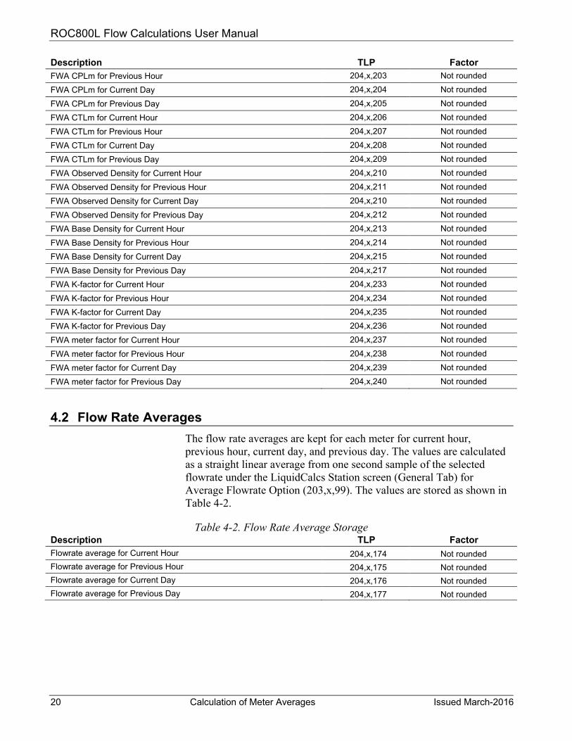
4.2 Flow Rate Averages
The flow rate averages are kept for each meter for current hour, previous hour, current day, and previous day. The values are calculated as a straight linear average from one second sample of the selected flowrate under the LiquidCalcs Station screen (General Tab) for Average Flowrate Option (203,x,99). The values are stored as shown in Table 4-2.
Table 4-2. Flow Rate Average Storage Description TLP Factor Flowrate average for Current Hour 204,x,174 Not rounded Flowrate average for Previous Hour 204,x,175 Not rounded Flowrate average for Current Day 204,x,176 Not rounded Flowrate average for Previous Day 204,x,177 Not rounded

ROC800L Flow Calculations User Manual
Issued March-2016 Calculation of Batch Averages and Totals 21
Chapter 5 – Calculations of Batch Averages and Totals
In This Chapter
5.1 Opening and Closing Meter Readings .............................................. 21 5.2 Indicated Volume Totals ................................................................... 21 5.3 Gross Volume Totals ........................................................................ 22 5.4 Gross Standard Volume Totals ......................................................... 22 5.5 Net Standard Volume Totals ............................................................. 22 5.6 Sediment and Water Volume Totals ................................................. 23 5.7 Mass Totals ....................................................................................... 23 5.8 Flow-Weighted Temperature Average .............................................. 24 5.9 Flow-Weighted Pressure Average .................................................... 24 5.10 Flow-Weighted Density Average ...................................................... 25 5.11 Flow Weighted Correction Factor Average ....................................... 25
This chapter describes the calculation and rounding methods to calculate the flow-weighted averages and quantity totals over a batch.
5.1 Opening and Closing Meter Readings The opening meter reading (MRo) is obtained by reading the non-resettable IV Total (described in Section 2) at the start of the batch. The closing meter reading (MRc) is obtained by reading the non-resettable IV total at the end of the batch. Refer to Table 5-1.
MRo = ROUND(Non-resettable IV Total @ Batch Start) MRc = ROUND(Non-resettable IV Total @ Batch Start)
Table 5-1. Open and Closing Meter Readings Description TLP Bbls gal ft3 MCF m3 Km3 L Non-resettable IV Total 204,x,145 N/A N/A N/A N/A N/A N/A N/A Opening Meter Reading (MRo)
214,x,64 x.xx x.xx x.xxx x.xxxxx x.xxx x.xxxxx xx.0
Closing Meter Reading (MRc)
214,x,90 x.xx x.xx x.xxx x.xxxxx x.xxx x.xxxxx xx.0
5.2 Indicated Volume Totals
The indicated volume total for the batch is calculated as:
octotal MRMRIV −= The indicated volume total for the batch is then rounded per Table 5-2.
Table 5-2. Indicated Volume Total Description TLP Bbls gal ft3 MCF m3 Km3 L Batch IV Total 204,x,16 x.xx x.xx x.xxx x.xxxxx x.xxx x.xxxxx x.x

ROC800L Flow Calculations User Manual
22 Calculation of Batch Averages and Totals Issued March-2016
5.3 Gross Volume Totals The gross volume total for the batch is calculated as:
octotal GVGVGV −= Where:
GVo = Non-resettable Gross Volume Total at batch start GVc = Non-resettable Gross Volume Total at batch end GVtotal = Gross Volume Total for the batch
Table 5-3. Gross Volume Total Description TLP Bbls gal ft3 MCF m3 Km3 L Non-resettable GV Total 204,x,146 N/A N/A N/A N/A N/A N/A N/A
Batch Start GV (GVo) 214,x,65 x.xx x.xx x.xxx x.xxxxx x.xxx x.xxxxx xx.x
Batch End GV (GVc) 214,x,91 x.xx x.xx x.xxx x.xxxxx x.xxx x.xxxxx xx.x
Batch End GV Total (GVtotal) 214,x,17 x.xx x.xx x.xxx x.xxxxx x.xxx x.xxxxx xx.x
5.4 Gross Standard Volume Totals The gross standard volume total for the batch is calculated as:
octotal GSVGSVGSV −= Where:
GSVo = Non-resettable Gross Standard Volume Total at batch start GSVc = Non-resettable Gross Standard Volume Total at batch end GSVtotal = Gross Standard Volume Total for the batch
Table 5-4. Gross Standard Volume Total Description TLP Bbls gal ft3 MCF m3 Km3 L Non-resettable GSV Total 204,x,147 N/A N/A N/A N/A N/A N/A N/A Batch Start GSV (GSVo) 214,x,66 x.xx x.xx x.xxx x.xxxxx x.xxx x.xxxxx xx.x Batch End GSV (GSVc) 214,x,92 x.xx x.xx x.xxx x.xxxxx x.xxx x.xxxxx xx.x Batch End GSV Total (GSVtotal)
214,x,18 x.xx x.xx x.xxx x.xxxxx x.xxx x.xxxxx xx.x
5.5 Net Standard Volume Totals
The net standard volume total for the batch is calculated as:
octotal NSVNSVNSV −= Where:
NSVo = Non-resettable Net Standard Volume Total at batch start
NSVc = Non-resettable Net Standard Volume Total at batch end
NSVtotal = Net Standard Volume Total for the batch
ROC800L Flow Calculations User Manual
Issued March-2016 Calculation of Batch Averages and Totals 23
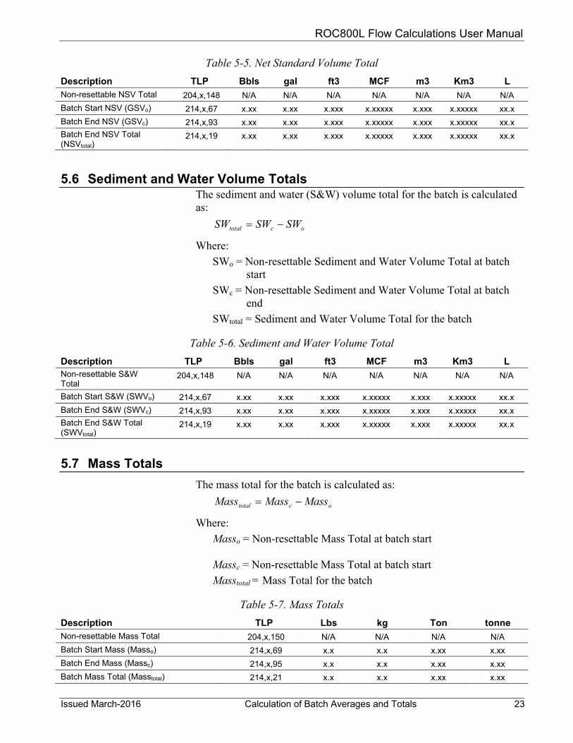
Table 5-5. Net Standard Volume Total Description TLP Bbls gal ft3 MCF m3 Km3 L Non-resettable NSV Total 204,x,148 N/A N/A N/A N/A N/A N/A N/A Batch Start NSV (GSVo) 214,x,67 x.xx x.xx x.xxx x.xxxxx x.xxx x.xxxxx xx.x Batch End NSV (GSVc) 214,x,93 x.xx x.xx x.xxx x.xxxxx x.xxx x.xxxxx xx.x Batch End NSV Total (NSVtotal)
214,x,19 x.xx x.xx x.xxx x.xxxxx x.xxx x.xxxxx xx.x
5.6 Sediment and Water Volume Totals
The sediment and water (S&W) volume total for the batch is calculated as:
octotal SWSWSW −= Where:
SWo = Non-resettable Sediment and Water Volume Total at batch start
SWc = Non-resettable Sediment and Water Volume Total at batch end
SWtotal = Sediment and Water Volume Total for the batch
Table 5-6. Sediment and Water Volume Total Description TLP Bbls gal ft3 MCF m3 Km3 L Non-resettable S&W Total
204,x,148 N/A N/A N/A N/A N/A N/A N/A
Batch Start S&W (SWVo) 214,x,67 x.xx x.xx x.xxx x.xxxxx x.xxx x.xxxxx xx.x Batch End S&W (SWVc) 214,x,93 x.xx x.xx x.xxx x.xxxxx x.xxx x.xxxxx xx.x Batch End S&W Total (SWVtotal)
214,x,19 x.xx x.xx x.xxx x.xxxxx x.xxx x.xxxxx xx.x
5.7 Mass Totals The mass total for the batch is calculated as:
octotal MassMassMass −= Where:
Masso = Non-resettable Mass Total at batch start Massc = Non-resettable Mass Total at batch start Masstotal = Mass Total for the batch
Table 5-7. Mass Totals Description TLP Lbs kg Ton tonne Non-resettable Mass Total 204,x,150 N/A N/A N/A N/A Batch Start Mass (Masso) 214,x,69 x.x x.x x.xx x.xx Batch End Mass (Massc) 214,x,95 x.x x.x x.xx x.xx Batch Mass Total (Masstotal) 214,x,21 x.x x.x x.xx x.xx

ROC800L Flow Calculations User Manual
24 Calculation of Batch Averages and Totals Issued March-2016
5.8 Flow-Weighted Temperature Average The flow-weighted meter temperature average and a flow weighted observed temperature average (if an observed density input is configured) for the batch is calculated as:
t
ii
QQT
TWA)( ×Σ
=
Where:
TWA = Flow-Weighted Temperature Average over the batch Ti = Temperature sample at time i Qi = Incremental quantity at time i Qt = Total quantity over the batch
The quantity used is the quantity selected under the LiquidCalcs Station screen (General Tab) for Average Flowrate Option (203,x,99). A sample is taken once per second and the final value is rounded per Table 5-8.
Table 5-8. Flow-Weighted Temperature Average Description TLP Deg F Deg C Flow-Weighted temperature average 214,x,25 x.x x.x5 Flow-Weighted observed temperature average 214,x,38 x.x x.x5
5.9 Flow-Weighted Pressure Average The flow-weighted meter pressure average and a flow weighted observed pressure average (if an observed density is present) for the batch is calculated as follows:
t
ii
QQP
PWA)( ×Σ
=
Where:
PWA = Flow-Weighted Pressure Average over the batch Ti = Pressure sample at time i Qi = Incremental quantity at time i Qt = Total quantity over the batch
The quantity used as the flow-weighting factor is the quantity selected under the LiquidCalcs Station screen (General Tab) for Average Flowrate Option (203,x,99). A sample is taken once per second and the final value is rounded per the Table 5-9.
Table 5-9. Flow-Weighted Pressure Average Description TLP PSIG kPa(g) barg kg/cm2
Flow-Weighted pressure average 214,x,24 x.0 x.0 x.x x.x Flow-Weighted observed pressure average 214,x,39 x.0 x.0 x.x x.x

ROC800L Flow Calculations User Manual
Issued March-2016 Calculation of Batch Averages and Totals 25
5.10 Flow-Weighted Density Average The flow weighted base density, observed density, and meter density are calculated over the batch. Each flow-weighted density average for the batch is calculated as:
t
ii
QQD
DWA)( ×Σ
=
Where:
DWA = Flow-Weighted Density Average over the batch Di = Density sample at time i Qi = Incremental quantity at time i Qt = Total quantity over the batch
The quantity used as the flow weighting factor is the quantity selected under the LiquidCalcs Station screen (General Tab) for Average Flowrate Option (203,x,99). A sample is taken once per second and the final value is rounded per the Table 5-9.
Table 5-10. Flow-Weighted Density Average Description TLP kg/m3 kg/L RD API gcc Lb/Bbl Lb/gal Lb/ft3 Flow-Weighted base density
214,x,26 x.x x.xxxx x.xxxx x.x x.xxxx x.x x.xxx x.xx
Flow-Weighted observed density average
214,x,27 x.x x.xxxx x.xxxx x.x x.xxxx x.x x.xxx x.xx
Flow-Weighted meter density average
214,x,28 x.x x.xxxx x.xxxx x.x x.xxxx x.x x.xxx x.xx
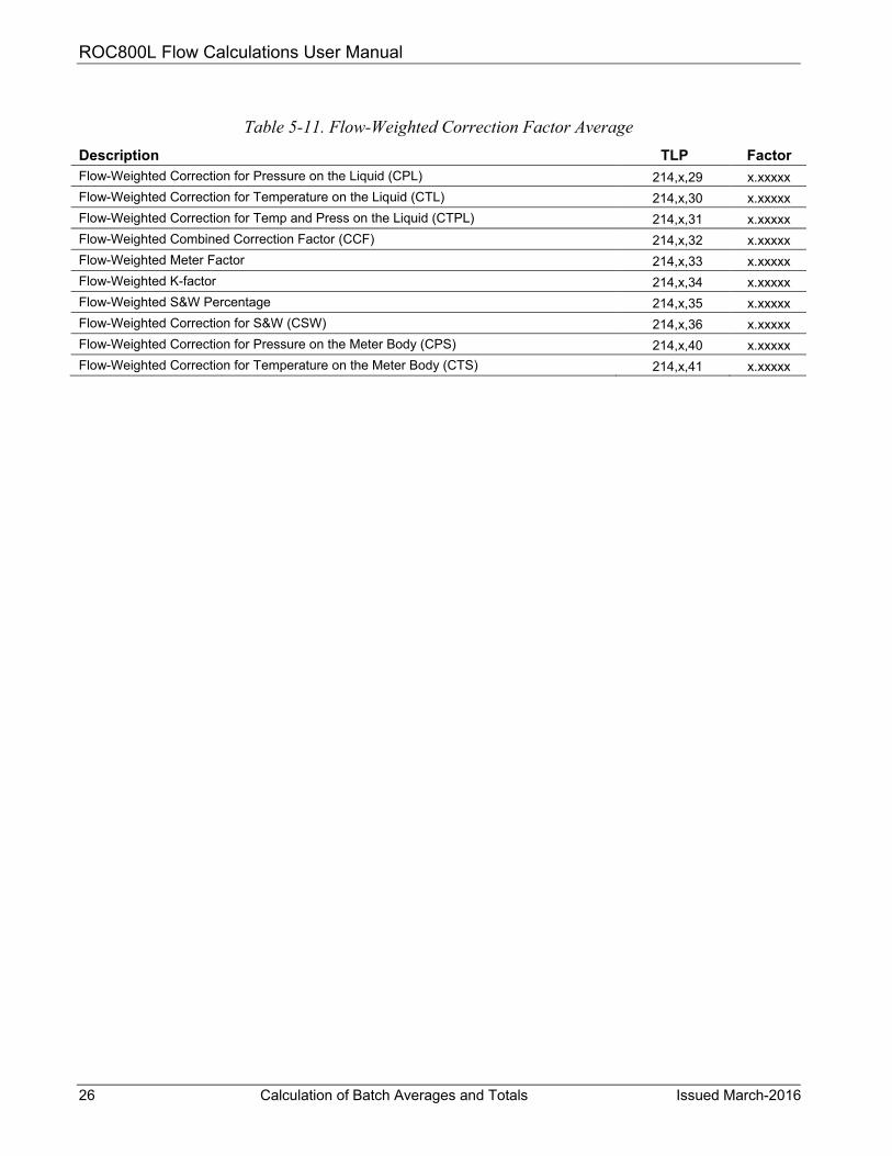
5.11 Flow Weighted Correction Factor Average The flow weighted CPL, CTL, CTPL (or VCF), S&W Percent, CSW, CPS, CTS, CCF, Meter Factor, and K-factor are calculated over the batch. Each flow-weighted factor average for the batch is calculated as:
t
ii
QQF
FWA)( ×Σ
=
Where:
FWA = Flow Weighted Factor Average over the batch Fi = Sample of factor at time i Qi = Incremental quantity at time i Qt = Total quantity over the batch
The quantity used as the flow-weighting factor is the quantity selected under the LiquidCalcs Station screen (General Tab) for Average Flowrate Option (203,x,99). A sample is taken once per second and the final value is rounded per the table below.
ROC800L Flow Calculations User Manual
26 Calculation of Batch Averages and Totals Issued March-2016
Table 5-11. Flow-Weighted Correction Factor Average
Description TLP Factor Flow-Weighted Correction for Pressure on the Liquid (CPL) 214,x,29 x.xxxxx Flow-Weighted Correction for Temperature on the Liquid (CTL) 214,x,30 x.xxxxx Flow-Weighted Correction for Temp and Press on the Liquid (CTPL) 214,x,31 x.xxxxx Flow-Weighted Combined Correction Factor (CCF) 214,x,32 x.xxxxx Flow-Weighted Meter Factor 214,x,33 x.xxxxx Flow-Weighted K-factor 214,x,34 x.xxxxx Flow-Weighted S&W Percentage 214,x,35 x.xxxxx Flow-Weighted Correction for S&W (CSW) 214,x,36 x.xxxxx Flow-Weighted Correction for Pressure on the Meter Body (CPS) 214,x,40 x.xxxxx Flow-Weighted Correction for Temperature on the Meter Body (CTS) 214,x,41 x.xxxxx
ROC800L Flow Calculations User Manual
Issued March-2016 Calculation of Meter Factor Using Volume Displacement Proving 27
Chapter 6 – Calculation of Meter Factor using Volume Displacement Proving
In This Chapter
6.1 Calculation of Gross Standard Prover Volume (GSVp) .................... 27 6.1.1 Calculation of Correction for Temperature on the
Prover Body ........................................................................... 28 6.1.2 Calculation of Correction for Pressure on the
Prover Body ........................................................................... 29 6.2 Calculation of the Volume of the Liquid through the
Meter at Base Conditions (ISVm) ..................................................... 29 6.3 Calculation of Meter Factor and Repeatability using
Average Meter Factor Method .......................................................... 30 6.3.1 Calculation of Trial Run Meter Factor ................................... 30 6.3.2 Average Trial Run Pressure .................................................. 31 6.3.3 Average Trial Run Temperature ............................................ 32 6.3.4 Repeatability Calculation ....................................................... 32 6.3.5 Final Meter Factor Calculation .............................................. 32
6.4 Calculation of Meter Factor and Repeatability using Average Data Method .............................................................................................. 33
6.4.1 Repeatability Calculation ....................................................... 33 6.4.2 Average Pulse Calculation .................................................... 33 6.4.3 Average Pressure Calculation ............................................... 34 6.4.4 Average Temperature Calculation......................................... 34 6.4.5 Meter Factor Calculation ....................................................... 34
This chapter describes the calculation and rounding methods used to calculate a meter factor from a successful prove for both average data method and average meter factor method, including rounding.
6.1 Calculation of Gross Standard Prover Volume (GSVp) The gross standard volume of the prover (volume of the prover at base conditions) is calculated as:
pp CCFBVGSV *=
Where: GSVp = Gross Standard Volume of the Prover BV = Base (Calibrated) Volume of the Prover CCFp = Combined Correction Factor of the Prover
The base volume and the gross standard volume of the prover are rounded as shown in Table 6-1.
ROC800L Flow Calculations User Manual
28 Calculation of Meter Factor Using Volume Displacement Proving Issued March-2016
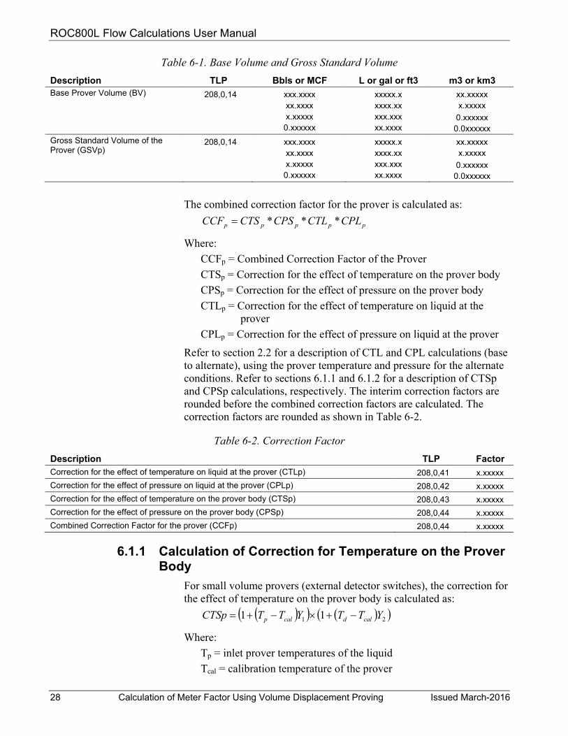
Table 6-1. Base Volume and Gross Standard Volume Description TLP Bbls or MCF L or gal or ft3 m3 or km3 Base Prover Volume (BV) 208,0,14 xxx.xxxx
xx.xxxx x.xxxxx 0.xxxxxx
xxxxx.x xxxx.xx xxx.xxx xx.xxxx
xx.xxxxx x.xxxxx
0.xxxxxx 0.0xxxxxx
Gross Standard Volume of the Prover (GSVp)
208,0,14 xxx.xxxx xx.xxxx x.xxxxx 0.xxxxxx
xxxxx.x xxxx.xx xxx.xxx xx.xxxx
xx.xxxxx x.xxxxx
0.xxxxxx 0.0xxxxxx
The combined correction factor for the prover is calculated as:
ppppp CPLCTLCPSCTSCCF ***=
Where: CCFp = Combined Correction Factor of the Prover CTSp = Correction for the effect of temperature on the prover body CPSp = Correction for the effect of pressure on the prover body CTLp = Correction for the effect of temperature on liquid at the
prover CPLp = Correction for the effect of pressure on liquid at the prover
Refer to section 2.2 for a description of CTL and CPL calculations (base to alternate), using the prover temperature and pressure for the alternate conditions. Refer to sections 6.1.1 and 6.1.2 for a description of CTSp and CPSp calculations, respectively. The interim correction factors are rounded before the combined correction factors are calculated. The correction factors are rounded as shown in Table 6-2.
Table 6-2. Correction Factor Description TLP Factor Correction for the effect of temperature on liquid at the prover (CTLp) 208,0,41 x.xxxxx Correction for the effect of pressure on liquid at the prover (CPLp) 208,0,42 x.xxxxx Correction for the effect of temperature on the prover body (CTSp) 208,0,43 x.xxxxx Correction for the effect of pressure on the prover body (CPSp) 208,0,44 x.xxxxx Combined Correction Factor for the prover (CCFp) 208,0,44 x.xxxxx
6.1.1 Calculation of Correction for Temperature on the Prover Body
For small volume provers (external detector switches), the correction for the effect of temperature on the prover body is calculated as:
( )( ) ( )( )21 11 YTTYTTCTSp caldcalp −+×−+=
Where: Tp = inlet prover temperatures of the liquid Tcal = calibration temperature of the prover

ROC800L Flow Calculations User Manual
Issued March-2016 Calculation of Meter Factor Using Volume Displacement Proving 29
Y1 = thermal coefficient of radial expansion of the prover material (/Deg)
Td = temperature of the displacer shaft Y2 = thermal coefficient of linear expansion of the prover material
(/Deg)
For large volume provers (internal detector switches), the correction for the effect of temperature on the prover body is calculated as:
( )YTTCTSp calp −+=1
Where: Tp = average of the inlet and outlet prover temperatures of the
liquid (/Deg) Tcal = calibration temperature of the prover (/Deg) Y = thermal coefficient of cubic expansion of the prover material
(/Deg)
6.1.2 Calculation of Correction for Pressure on the Prover Body
For single-walled prover, the correction for the effect of pressure on the prover body is calculated as:
( )tE
DPPCPS calpp ×−+=1
Where: Pp = average of the inlet and outlet prover pressures of the liquid Pcal = calibration pressure of the prover D = inside diameter of the prover tube E = Youngs modulus of elasticity of the prover tube steel t = wall thickness of the prover tube
For a double-walled prover, there is no correction for the effect of pressure and CPSp is set equal to 1.0.
6.2 Calculation of the Volume of the Liquid through the Meter at Base Conditions (ISVm)
The indicated standard volume of the liquid at the meter (ISVm) is calculated as:
mm CCFfactorK
PulseCountISV *−
=
Where: ISVm = Indicated Standard Volume of Liquid at the Meter Pulse Count = Number of pulses received at the meter (whole or
interpolated)
ROC800L Flow Calculations User Manual
30 Calculation of Meter Factor Using Volume Displacement Proving Issued March-2016
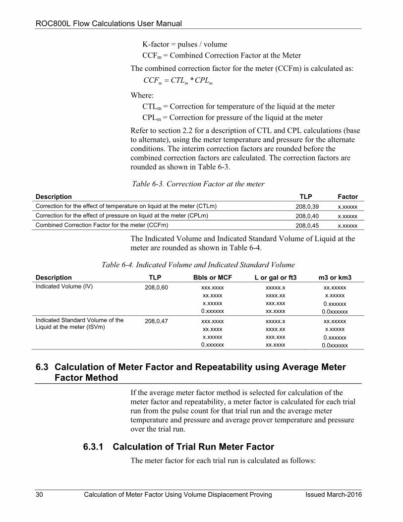
K-factor = pulses / volume CCFm = Combined Correction Factor at the Meter
The combined correction factor for the meter (CCFm) is calculated as:
mmm CPLCTLCCF *=
Where: CTLm = Correction for temperature of the liquid at the meter CPLm = Correction for pressure of the liquid at the meter
Refer to section 2.2 for a description of CTL and CPL calculations (base to alternate), using the meter temperature and pressure for the alternate conditions. The interim correction factors are rounded before the combined correction factors are calculated. The correction factors are rounded as shown in Table 6-3.
Table 6-3. Correction Factor at the meter Description TLP Factor Correction for the effect of temperature on liquid at the meter (CTLm) 208,0,39 x.xxxxx Correction for the effect of pressure on liquid at the meter (CPLm) 208,0,40 x.xxxxx Combined Correction Factor for the meter (CCFm) 208,0,45 x.xxxxx
The Indicated Volume and Indicated Standard Volume of Liquid at the meter are rounded as shown in Table 6-4.
Table 6-4. Indicated Volume and Indicated Standard Volume Description TLP Bbls or MCF L or gal or ft3 m3 or km3 Indicated Volume (IV) 208,0,60 xxx.xxxx
xx.xxxx x.xxxxx 0.xxxxxx
xxxxx.x xxxx.xx xxx.xxx xx.xxxx
xx.xxxxx x.xxxxx
0.xxxxxx 0.0xxxxxx
Indicated Standard Volume of the Liquid at the meter (ISVm)
208,0,47 xxx.xxxx xx.xxxx x.xxxxx 0.xxxxxx
xxxxx.x xxxx.xx xxx.xxx xx.xxxx
xx.xxxxx x.xxxxx
0.xxxxxx 0.0xxxxxx
6.3 Calculation of Meter Factor and Repeatability using Average Meter Factor Method
If the average meter factor method is selected for calculation of the meter factor and repeatability, a meter factor is calculated for each trial run from the pulse count for that trial run and the average meter temperature and pressure and average prover temperature and pressure over the trial run.
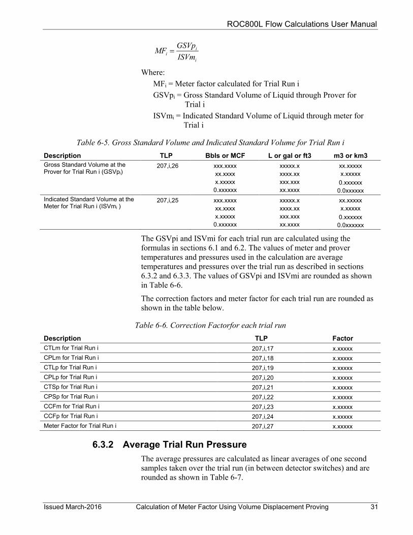
6.3.1 Calculation of Trial Run Meter Factor The meter factor for each trial run is calculated as follows:
ROC800L Flow Calculations User Manual
Issued March-2016 Calculation of Meter Factor Using Volume Displacement Proving 31
i
ii ISVm
GSVpMF =
Where: MFi = Meter factor calculated for Trial Run i GSVpi = Gross Standard Volume of Liquid through Prover for
Trial i ISVmi = Indicated Standard Volume of Liquid through meter for
Trial i
Table 6-5. Gross Standard Volume and Indicated Standard Volume for Trial Run i Description TLP Bbls or MCF L or gal or ft3 m3 or km3 Gross Standard Volume at the Prover for Trial Run i (GSVpi)
207,i,26 xxx.xxxx xx.xxxx x.xxxxx 0.xxxxxx
xxxxx.x xxxx.xx xxx.xxx xx.xxxx
xx.xxxxx x.xxxxx
0.xxxxxx 0.0xxxxxx
Indicated Standard Volume at the Meter for Trial Run i (ISVmi )
207,i,25 xxx.xxxx xx.xxxx x.xxxxx 0.xxxxxx
xxxxx.x xxxx.xx xxx.xxx xx.xxxx
xx.xxxxx x.xxxxx
0.xxxxxx 0.0xxxxxx
The GSVpi and ISVmi for each trial run are calculated using the formulas in sections 6.1 and 6.2. The values of meter and prover temperatures and pressures used in the calculation are average temperatures and pressures over the trial run as described in sections 6.3.2 and 6.3.3. The values of GSVpi and ISVmi are rounded as shown in Table 6-6.
The correction factors and meter factor for each trial run are rounded as shown in the table below.
Table 6-6. Correction Factorfor each trial run Description TLP Factor CTLm for Trial Run i 207,i,17 x.xxxxx CPLm for Trial Run i 207,i,18 x.xxxxx CTLp for Trial Run i 207,i,19 x.xxxxx CPLp for Trial Run i 207,i,20 x.xxxxx CTSp for Trial Run i 207,i,21 x.xxxxx CPSp for Trial Run i 207,i,22 x.xxxxx CCFm for Trial Run i 207,i,23 x.xxxxx CCFp for Trial Run i 207,i,24 x.xxxxx Meter Factor for Trial Run i 207,i,27 x.xxxxx
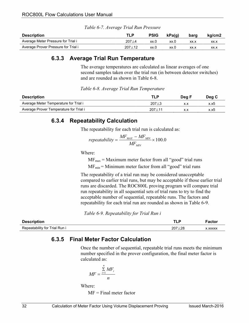
6.3.2 Average Trial Run Pressure The average pressures are calculated as linear averages of one second samples taken over the trial run (in between detector switches) and are rounded as shown in Table 6-7.
ROC800L Flow Calculations User Manual
32 Calculation of Meter Factor Using Volume Displacement Proving Issued March-2016
Table 6-7. Average Trial Run Pressure Description TLP PSIG kPa(g) barg kg/cm2
Average Meter Pressure for Trial i 207,i,4 xx.0 xx.0 xx.x xx.x Average Prover Pressure for Trial i 207,i,12 xx.0 xx.0 xx.x xx.x
6.3.3 Average Trial Run Temperature The average temperatures are calculated as linear averages of one second samples taken over the trial run (in between detector switches) and are rounded as shown in Table 6-8.
Table 6-8. Average Trial Run Temperature
Description TLP Deg F Deg C Average Meter Temperature for Trial i 207,i,3 x.x x.x5 Average Prover Temperature for Trial i 207,i,11 x.x x.x5
6.3.4 Repeatability Calculation The repeatability for each trial run is calculated as:
0.100×−
=MIN
MINMAX
MFMFMF
ityrepeatabil
Where: MFmax = Maximum meter factor from all “good” trial runs MFmin = Minimum meter factor from all “good” trial runs
The repeatability of a trial run may be considered unacceptable compared to earlier trial runs, but may be acceptable if those earlier trial runs are discarded. The ROC800L proving program will compare trial run repeatability in all sequential sets of trial runs to try to find the acceptable number of sequential, repeatable runs. The factors and repeatability for each trial run are rounded as shown in Table 6-9.
Table 6-9. Repeatability for Trial Run i
Description TLP Factor Repeatability for Trial Run i 207,i,28 x.xxxxx
6.3.5 Final Meter Factor Calculation Once the number of sequential, repeatable trial runs meets the minimum number specified in the prover configuration, the final meter factor is calculated as:
n
MFMF
i
n
i 1=Σ
=
Where: MF = Final meter factor
ROC800L Flow Calculations User Manual
Issued March-2016 Calculation of Meter Factor Using Volume Displacement Proving 33
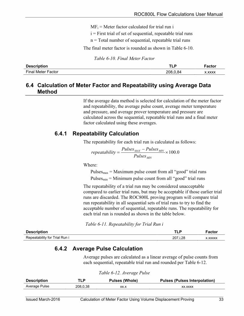
MFi = Meter factor calculated for trial run i i = First trial of set of sequential, repeatable trial runs n = Total number of sequential, repeatable trial runs
The final meter factor is rounded as shown in Table 6-10.
Table 6-10. Final Meter Factor Description TLP Factor Final Meter Factor 208,0,84 x.xxxx
6.4 Calculation of Meter Factor and Repeatability using Average Data Method
If the average data method is selected for calculation of the meter factor and repeatability, the average pulse count, average meter temperature and pressure, and average prover temperature and pressure are calculated across the sequential, repeatable trial runs and a final meter factor calculated using these averages.
6.4.1 Repeatability Calculation The repeatability for each trial run is calculated as follows:
0.100×−
=MIN
MINMAX
PulsesPulsesPulses
ityrepeatabil
Where: Pulsesmax = Maximum pulse count from all “good” trial runs Pulsesmin = Minimum pulse count from all “good” trial runs
The repeatability of a trial run may be considered unacceptable compared to earlier trial runs, but may be acceptable if those earlier trial runs are discarded. The ROC800L proving program will compare trial run repeatability in all sequential sets of trial runs to try to find the acceptable number of sequential, repeatable runs. The repeatability for each trial run is rounded as shown in the table below.
Table 6-11. Repeatability for Trial Run i Description TLP Factor Repeatability for Trial Run i 207,i,28 x.xxxxx
6.4.2 Average Pulse Calculation Average pulses are calculated as a linear average of pulse counts from each sequential, repeatable trial run and rounded per Table 6-12.
Table 6-12. Average Pulse Description TLP Pulses (Whole) Pulses (Pulses Interpolation) Average Pulse 208,0,38 xx.x xx.xxxx

ROC800L Flow Calculations User Manual
34 Calculation of Meter Factor Using Volume Displacement Proving Issued March-2016
6.4.3 Average Pressure Calculation A linear average of the meter pressure and a linear average of the prover pressure over each trial run are calculated as described in section 5.3. Final averages are calculated as linear averages of the trial run data from each of the sequential, repeatable trial runs. These pressure average values are rounded per Table 6-13.
Table 6-13. Average Pressure Description TLP PSIG kPa(g) barg kg/cm2
Average Meter Pressure 208,0,24 xx.0 xx.0 xx.x xx.x Average Prover Pressure 208,0,33 xx.0 xx.0 xx.x xx.x
6.4.4 Average Temperature Calculation A linear average of the meter temperature and a linear average of the prover temperature over each trial run are calculated as described in Section 6.3. Final averages are calculated as linear averages of the trial run data from each of the sequential, repeatable trial runs. These temperature average values are rounded per Table 6-14.
Table 6-14. Final Average Temperature Description TLP Deg F Deg C Final Average Meter Temperature 208,0,23 x.x x.x5 Final Average Prover Temperature 208,0,32 x.x x.x5
6.4.5 Meter Factor Calculation The final meter factor is calculated as:
avg
avg
ISVmGSVp
MF =
Where: MF = Final Meter Factor GSVpavg= Gross Standard Volume of Liquid through Prover ISVmavg=Indicated Standard Volume of Liquid through Meter
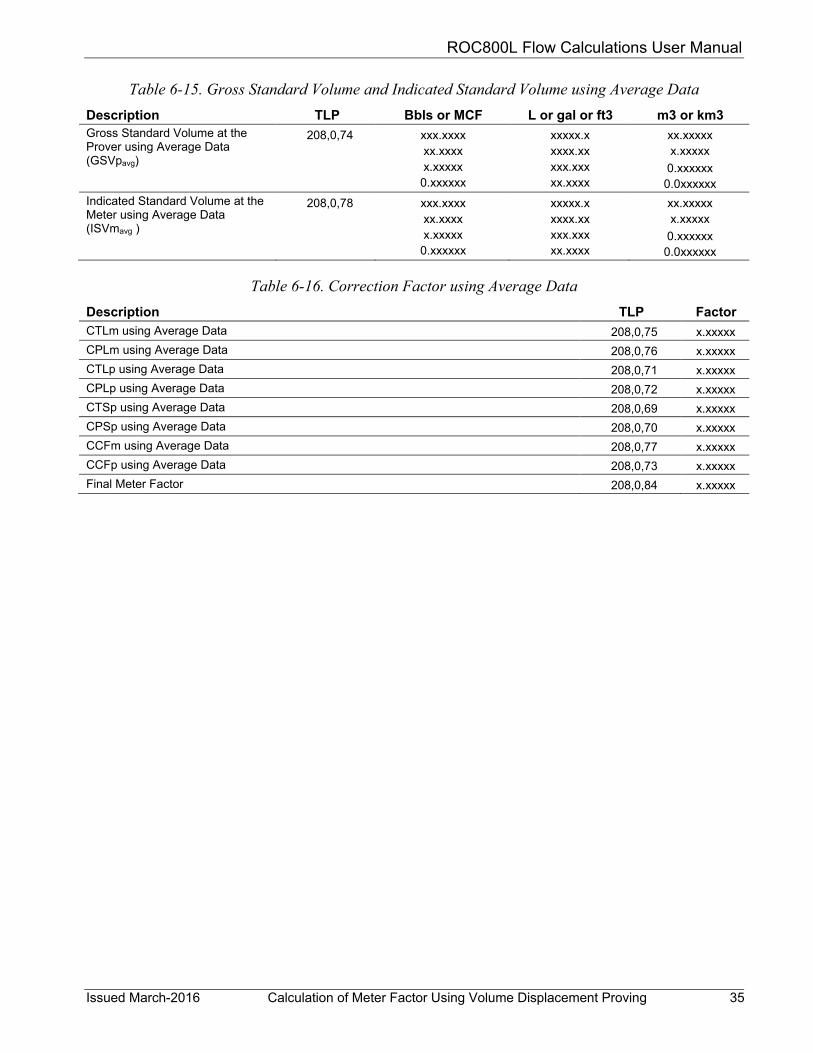
The GSVp and ISVm values are calculated using the formulas in Sections 6.1 and 6.2. The pulse count and values of meter and prover temperatures and pressures used in the calculation are the average values calculated over the sequential, repeatable trial runs as described in Sections 6.4.2, 6.4.3, and 6.4.4. The values are rounded as shown in Tables 6-15 and 6-16.
ROC800L Flow Calculations User Manual
Issued March-2016 Calculation of Meter Factor Using Volume Displacement Proving 35
Table 6-15. Gross Standard Volume and Indicated Standard Volume using Average Data Description TLP Bbls or MCF L or gal or ft3 m3 or km3 Gross Standard Volume at the Prover using Average Data (GSVpavg)
208,0,74 xxx.xxxx xx.xxxx x.xxxxx 0.xxxxxx
xxxxx.x xxxx.xx xxx.xxx xx.xxxx
xx.xxxxx x.xxxxx
0.xxxxxx 0.0xxxxxx
Indicated Standard Volume at the Meter using Average Data (ISVmavg )
208,0,78 xxx.xxxx xx.xxxx x.xxxxx 0.xxxxxx
xxxxx.x xxxx.xx xxx.xxx xx.xxxx
xx.xxxxx x.xxxxx
0.xxxxxx 0.0xxxxxx
Table 6-16. Correction Factor using Average Data Description TLP Factor CTLm using Average Data 208,0,75 x.xxxxx CPLm using Average Data 208,0,76 x.xxxxx CTLp using Average Data 208,0,71 x.xxxxx CPLp using Average Data 208,0,72 x.xxxxx CTSp using Average Data 208,0,69 x.xxxxx CPSp using Average Data 208,0,70 x.xxxxx CCFm using Average Data 208,0,77 x.xxxxx CCFp using Average Data 208,0,73 x.xxxxx Final Meter Factor 208,0,84 x.xxxxx
ROC800L Flow Calculations User Manual
For customer service and technical support, visit www.EmersonProcess.com/Remote/Support.
Global Headquarters, North America, and Latin America:
Emerson Process Management Remote Automation Solutions 6005 Rogerdale Road Houston, TX 77072 U.S.A. T +1 281 879 2699 | F +1 281 988 4445 www.EmersonProcess.com/Remote
© 2016 Remote Automation Solutions, a business unit of Emerson Process Management. All rights reserved.
Remote Automation Solutions, a business unit of Emerson Process Management, shall not be liable for technical or editorial errors in this manual or omissions from this manual. REMOTE AUTOMATION SOLUTIONS MAKES NO WARRANTIES, EXPRESSED OR IMPLIED, INCLUDING THE IMPLIED WARRANTIES OF MERCHANTABILITY AND FITNESS FOR A PARTICULAR PURPOSE WITH RESPECT TO THIS MANUAL AND, IN NO EVENT SHALL REMOTE AUTOMATION SOLUTIONS BE LIABLE FOR ANY INCIDENTAL, PUNITIVE, SPECIAL OR CONSEQUENTIAL DAMAGES INCLUDING, BUT NOT LIMITED TO, LOSS OF PRODUCTION, LOSS OF PROFITS, LOSS OF REVENUE OR USE AND COSTS INCURRED INCLUDING WITHOUT LIMITATION FOR CAPITAL, FUEL AND POWER, AND CLAIMS OF THIRD PARTIES.
Emerson Process Management Ltd, Remote Automation Solutions (UK), is a wholly owned subsidiary of Emerson Electric Co. doing business as Remote Automation Solutions, a business unit of Emerson Process Management. FloBoss, ROCLINK, ControlWave, Helicoid, FBxConnect, and OpenEnterprise are trademarks of Remote Automation Solutions. AMS, PlantWeb, and the PlantWeb logo are marks owned by one of the companies in the Emerson Process Management business unit of Emerson Electric Co. Emerson Process Management, Emerson and the Emerson logo are trademarks and service marks of the Emerson Electric Co. All other marks are property of their respective owners.
The contents of this publication are presented for informational purposes only. While every effort has been made to ensure informational accuracy, they are not to be construed as warranties or guarantees, express or implied, regarding the products or services described herein or their use or applicability. Remote Automation Solutions reserves the right to modify or improve the designs or specifications of such products at any time without notice. All sales are governed by Remote Automation Solutions’ terms and conditions which are available upon request. Remote Automation Solutions does not assume responsibility for the selection, use or maintenance of any product. Responsibility for proper selection, use and maintenance of any Remote Automation Solutions product remains solely with the purchaser and end-user.
Europe: Emerson Process Management Remote Automation Solutions Unit 8, Waterfront Business Park Dudley Road, Brierley Hill Dudley UK DY5 1LX T +44 1384 487200 | F +44 1384 487258
Middle East/Africa: Emerson Process Management Remote Automation Solutions Emerson FZE P.O. Box 17033 Jebel Ali Free Zone – South 2 Dubai U.A.E. T +971 4 8118100 | F +971 4 8865465
Asia-Pacific: Emerson Process Management Remote Automation Solutions 1 Pandan Crescent Singapore 128461 T +65 6777 8211| F +65 6777 0947
Remote Automation Solutions