robust grid-oriented control of high voltage dc links
TRANSCRIPT

HAL Id: hal-01450076https://hal.archives-ouvertes.fr/hal-01450076
Submitted on 17 Mar 2020
HAL is a multi-disciplinary open accessarchive for the deposit and dissemination of sci-entific research documents, whether they are pub-lished or not. The documents may come fromteaching and research institutions in France orabroad, or from public or private research centers.
L’archive ouverte pluridisciplinaire HAL, estdestinée au dépôt et à la diffusion de documentsscientifiques de niveau recherche, publiés ou non,émanant des établissements d’enseignement et derecherche français ou étrangers, des laboratoirespublics ou privés.
Robust grid-oriented control of high voltage DC linksembedded in an AC transmission system International
Journal of Robust and Nonlinear Control †L Arioua, B Marinescu
To cite this version:L Arioua, B Marinescu. Robust grid-oriented control of high voltage DC links embedded in an ACtransmission system International Journal of Robust and Nonlinear Control †. International Journalof Robust and Nonlinear Control, Wiley, 2016, 26, pp.1944 - 1961. �hal-01450076�

INTERNATIONAL JOURNAL OF ROBUST AND NONLINEAR CONTROLInt. J. Robust Nonlinear Control 2016; 26:1944–1961Published online 29 July 2015 in Wiley Online Library (wileyonlinelibrary.com). DOI: 10.1002/rnc.3390
Robust grid-oriented control of high voltage DC links embeddedin an AC transmission system
L. Arioua1,2 and B. Marinescu �1,2,*,†
1RTE R&D Division, 9 rue de la Porte de Buc, Versailles, 78000, France2SATIE Laboratory, Ecole Normale Superièure de Cachan, 61, avenue du President Wilson, Cachan, 94230, France
SUMMARY
Several studies have shown that the way to design controllers for the high-voltage direct current (HVDC)links impacts the transient behavior of the electric system in which the latter are inserted. This can beexploited to improve the performances of the stability of the power system. In this paper, a robust multi-variable control design for the converters of an HVDC link is proposed. It is based on the coordination ofthe control actions of the HVDC converters and the use of a control model. The latter takes into consider-ation, in addition to the dynamics that mostly impact the stability of the neighbor zone of the HVDC link,several cases of faulted situations modeled as uncertainties. AnH1 controller allowed us to achieve robust-ness against such uncertainties. The new controller is tested in comparison with the standard vector controland an optimal linear quadratic controller using the EUROSTAG simulation software (Tractebel Engineering,Brussels, Belgium and Réseau de Transport d’Electricité (RTE) - France) on both academic and realisticlarge-scale power systems. Copyright © 2015 John Wiley & Sons, Ltd.
Received 19 March 2014; Revised 11 April 2015; Accepted 6 June 2015
KEY WORDS: HVDC; transient stability; H1 control; output-feedback control
1. INTRODUCTION
The high-voltage direct current (HVDC) link is a mean of transmission of electric power basedon high-power electronics. During the last decades, this kind of power transmission has obtainedgreat attention. In fact, many projects of insertion of HVDC links are undergoing. Because of itsrapid responses and flexibility, the HVDC technology is able to provide to the transmission systemadvantages as transfer capacity enhancement and power flow control [1]. Initially, it was used tointerconnect two asynchronous systems. In this case of use, the ends of the HVDC link are electri-cally independent, which avoids the propagation of perturbations (like, e.g., faults) between the twoalternating current (AC) areas. This is, for instance, the case of the England–France interconnection[2]. Nowadays, HVDC links are more and more inserted into the same AC power system in parallelwith other existing AC lines and other dynamic elements as generators. In this new context of usewhere the HVDC is embedded in a meshed AC system, all the elements are in interaction, and thestability of the neighbor zone of the HVDC link may be influenced by these interactions. This con-ducted us to find a way to take into consideration the aforementioned interactions during the controllaw synthesis. A new kind of mode—called electrical coupling mode—was put into evidence. Itinvolves dynamics of distant machines, and it is different from a well-known inter-area mode. Thesenew interactions allowed us to better identify the machines responsible for the transient stability ofthe neighbor zone of the HVDC link. This information was exploited to provide a new type of con-trol model. This new context of use of the HVDC links motivated several studies, which confirm
*Correspondence to: B. Marinescu, RTE R&D Division, 9 rue de la Porte de Buc, Versailles, 78000, France.†E-mail: [email protected]�Present address: IRCCyN-Ecole Centrale Nantes, 1, rue de la Noë, FR-44321 Nantes Cedex 3.
Copyright © 2015 John Wiley & Sons, Ltd.
,

ROBUST CONTROL OF HVDCs EMBEDDED IN AN AC GRIDS 1945
that the way to control the HVDC converters impacts the stability of the system in which the linkis embedded [3–8]. Several controller schemes have been proposed to enhance the dynamic perfor-mances of the neighbor zone of the HVDC link. In [9, 10], for instance, the control of the HVDCconverters is developed on the base of the model of the whole power system, but this approach isnot possible for large-scale power systems. Indeed, the major difficulty encountered during the con-trol law synthesis is the way to take into account the rest of the power system. In [11], for example,a coordinated controller based on on-line identification of the power system parameters has beendeveloped. In [12, 13], controllers for HVDC converters using remote information from generatorsare proposed. In [14], an adaptive optimal controller was synthesized using real-time system-widemeasurements. In the approaches cited previously, even if the rest of the power system is taken intoaccount, the use of remote data is unavoidable. These latter are not always available at the convert-ers’ stations, which limits the application of these methods. This conducted us to focus on the wayto take into consideration the power system according to the given grid objectives using only vari-ables available at converter stations. For this, an adequate control model is proposed and next usedfor the synthesis of the regulators of the HVDC link.
This paper presents thus a new method for developing a control model based on the analysis of theAC power system and particularly the AC zone surrounding the HVDC link. This analysis allowedus to determine the main dynamics impacting the power system stability. Moreover, in order to bettercapture the power system variations during a fault, critical faulted situations are considered duringthe synthesis. This led us to use a more efficient robust control design based on the H1 theory.
The paper is organized as follows: In Section 2, the analysis of the different interactions that existin the neighbor zone of the HVDC is presented, which allowed us to develop the nominal nonlinearcontrol model in Section 3. Section 4 is dedicated to the synthesis of the uncertain linear model. Thelatter is used in Section 5 to develop a robust multivariable output-feedback controller for the HVDCconverters. Finally, in Section 6, simulation results are presented to illustrate the performances androbustness of the new control strategy in comparison with those of standard ones.
2. ANALYSIS OF THE NEIGHBOR ZONE OF THE HIGH-VOLTAGEDIRECT CURRENT
We are focusing on the stability of the neighbor zone of the HVDC link. For this reason, we analyzethe different interactions that exist between the different power system dynamic elements. As it isexplained later, these interactions affect the stability of the power system especially when a severefault (short circuit, loss of a group, etc) occurs.
2.1. Power system stability problem
The stability of a power system may be broadly defined as its property to reach an equilibrium pointafter a disturbance as, for instance, a short circuit. Depending on whether the perturbations caused bythe fault are small or large, we speak about small-signal stability or, respectively, transient stability.One of the main concerns in both cases is the loss of synchronism of one or more generators. That is,the frequency of some generators of the grid cannot reach the equilibrium value (50 Hz in Europe)after a disturbance.
Small-signal stability [15]. It is the ability of the power system to maintain synchronism undersmall disturbances such as small variations of loads and generation. The disturbances are consid-ered sufficiently small to allow the use of the linear approximation of the dynamic system equations.The instability that may results can be of two forms: steady increase in rotor angle due to lack ofsufficient synchronizing torque or rotor oscillations of increasing amplitude due to lack of sufficientdamping torque. In today’s power systems, small-signal stability is largely a problem of insuffi-cient damped oscillations. The stability of the following types of oscillations is studied through themodal analysis of the linear approximation model. More specifically, this is reflected by two kindsof modes:
Copyright © 2015 John Wiley & Sons, Ltd. Int. J. Robust Nonlinear Control 2016; 26:1944–1961DOI: 10.1002/rnc

1946 L. ARIOUA AND B. MARINESCU
� Local modes related to the swing of a generator against the rest of the power system.� Inter-area modes related to the swing of several machines in one part of the system against
another group of machines in another part of the system.
Transient stability [15]. It is the ability of the power system to maintain synchronism when sub-jected to a severe transient disturbance like, for instance, short circuits. The system response to sucha disturbance involves large excursions of generator rotor angles because of the nonlinear power–angle relationship. Stability will then depend on both the operating state of the system at the timewhen the disturbance is applied and the severity of the disturbance. In the case of short circuits, thedegree of stability is quantified by the so-called critical clearing time (CCT), which is defined asthe maximal fault duration at a given location for which the system remains transiently stable [15].Thus, the CCT is a marge of stability of the power system.
More specifically, a short circuit systematically leads to two types of topology variations. The firstone corresponds to the modification of the entries of the grid admittance matrix, which correspond tothe branches impacted by the fault. The second one corresponds to the fault clearing (if the fault wason a branch, the clearing is performed by the trip of the branch). The latter topology modificationscan be easily captured into a linear model of the dynamic power system equations. However, becausethe power system is nonlinear, the final post disturbance and, thus, the CCT depend not only onthese topology variations.
Impact of the high-voltage direct current link on the system transient stability. Studies of the HVDClink inserted in a power system have investigated the impact of the HVDC on the transient stabilityand the small-signal stability of its neighbor zone. In [6], for instance, the author shows that theenhancement of the overall system dynamic performance of the neighbor zone of the HVDC link ispossible by minor modifications in the HVDC controls. In [16], the transient stability of the neighborzone of the HVDC link is assessed for different direct current (DC) power levels, which indicateshow the HVDC transmission can increase the CCT at several locations of the neighbor zone.
2.2. Electrical interactions and critical clearing time
Part of the electrical interactions that impact the transient stability can be described by several typesof modes. This is illustrated on the following example.
Example of application
Consider the simplified representation of the France–Spain–Portugal zones introduced in [17],which consists of 23 machines as shown in Figure 1. The system is represented by a detailed non-linear model including generators along with their regulations. Only the high-voltage network .225and 400 kV) is modeled. The interconnection between France and Spain, which consists of four AClines, is reinforced by adding a voltage source converter (VSC)-based HVDC link of 65-km lengthwith a nominal active power of 1000MW and a rated pole voltage of˙320 kV.
The interconnected power system is analyzed here for the perspective of the control of the HVDC.Thus, the open-loop input–output system defined by the controls U and measures y chosen for thecontrol of the converters of the HVDC should be considered (this model is described in detail inSection 4.1 by †NL in (3)). When linearized as explained in Section 4.1, a linear state-space form†L (given further on by (4)) is obtained. The singular values of the transfer matrix of †L presentedearlier are given in Figure 2. Two poorly damped modes are visible, and their characteristics aregiven in Table I.
The modal analysis of the whole system showed that the mode 1 is an inter-area mode. As a matterof fact, the states with higher participation in this mode are related to rotor dynamics (Table I).As recalled in Section 2.1, this kind of mode is due to the electrical coupling of geographicallydistant generators. It is thus of interest to quantify the impact of the HVDC on the stability of itsneighbor zone.
The second mode in Table I is not of inter-area nature because the states with higher participationin this mode are not associated to rotors but to D-axes. It is thus an electrical mode. However, notice
Copyright © 2015 John Wiley & Sons, Ltd. Int. J. Robust Nonlinear Control 2016; 26:1944–1961DOI: 10.1002/rnc

ROBUST CONTROL OF HVDCs EMBEDDED IN AN AC GRIDS 1947
Figure 1. France–Spain–Portugal interconnected systems.
Figure 2. Frequency response of the nominal model.
Table I. Machines with the highest participation in modes 1 and 2.
Machines with f Rotor D-axemajor participation [Hz] participation participation
Mode 1 G15 0.64 0.23 0.0035G23 0.21 0.003
Mode 2 G19 0.16 0.38 0.41G1 0.0063 0.038
that, as shown in Table I, several machines have important participations in this mode. This meansthat this kind of mode, although it is not of electromechanical nature as the inter-area ones, is alsodue to electrical coupling of distant machines and thus of interest for the analysis of the transientstability of a zone. This new type of mode is called in the sequel an electrical coupling mode. Indeed,to further investigate this aspect, consider that the benchmark of Figure 1 for which the impedanceof a line is directly connected to machine G19 (which is highly participating in mode 2, Table I) isvaried. Table II shows that there is a direct correlation between the length of this line, the dampingof mode 2, and the CCT computed at the terminal bus of G19.
Copyright © 2015 John Wiley & Sons, Ltd. Int. J. Robust Nonlinear Control 2016; 26:1944–1961DOI: 10.1002/rnc

1948 L. ARIOUA AND B. MARINESCU
Table II. Correlation between the length of theline, the damping of mode 2 and the CCT.
Impedance of Damping CCTthe line [pu] of the mode 2 [ms]
0.50 3.58 280.36 6.39 290.036 17.89 320.012 21.57 37
CCT, critical clearing time.
Table III. Selected critical machines.
Gen (Fr) CCT [ms] Gen (Sp) CCT [ms]
G16 64 G2 178G15 203 G8 179G17 205 G5 214G21 280 G6 235
Table IV. Machines with the highest participationin the poorly damped coupling modes.
Modes Damping of mode Machine kept
1 3.26 G152 6.40 G19
3. THE NOMINAL NONLINEAR CONTROL MODEL
A full large-scale simulation model of the interconnected power system is usually available andcurrently updated by the transmission system operators (TSOs) (e.g., [18, 19]). We have chosento use this kind of full model to extract a control model. The objective of this latter model is tocapture the dynamics that may impact the transient stability and that have the greatest impact on theneighbor zone of the HVDC link.
3.1. Machine selection strategy
First, as it has been explained in Section 2, the CCT is a good indicator of the transient stability levelof the HVDC link neighboring zone. Therefore, the strategy of machine selection adopted in thispaper is based on the computation of CCTs at well-chosen points of the neighbor zone. These pointsare determined by a priori stability studies (usually carried out by TSOs). To each case of fault,it associated the first machine, which loses synchronism and the corresponding CCT. The lowestvalues, which are situated under a chosen threshold, indicate the machines to be kept for the controlmodel. At this stage, the machines kept for the example in Figure 1 are presented in the Table III.
Second, in Section 2.2, it has been shown that two classes of coupling modes are connectedwith transient stability. They provide information about distant devices that impact the stabilityof the neighbor zone. The list of chosen machines for the control model made previously basedon local (CCT) considerations must thus be enriched by the most participating machines in thepoorly damped aforementioned coupling modes. This allowed us to identify the machines illustratedin Table IV.
Thus, the final list of retained machines is the list of Table III plus G19.
3.2. Network reduction
The topology is also reduced. More precisely, the buses to which the retained machines are con-nected are kept along with the end buses of the interconnections of interest (the HVDC link ones
Copyright © 2015 John Wiley & Sons, Ltd. Int. J. Robust Nonlinear Control 2016; 26:1944–1961DOI: 10.1002/rnc
ROBUST CONTROL OF HVDCs EMBEDDED IN AN AC GRIDS 1949
and the neighbor AC zone ones). The rest of the buses and branches are replaced by a WARD-PVmethod [20], that is, by equivalent impedances and injectors.
3.3. Model of the high-voltage direct current link
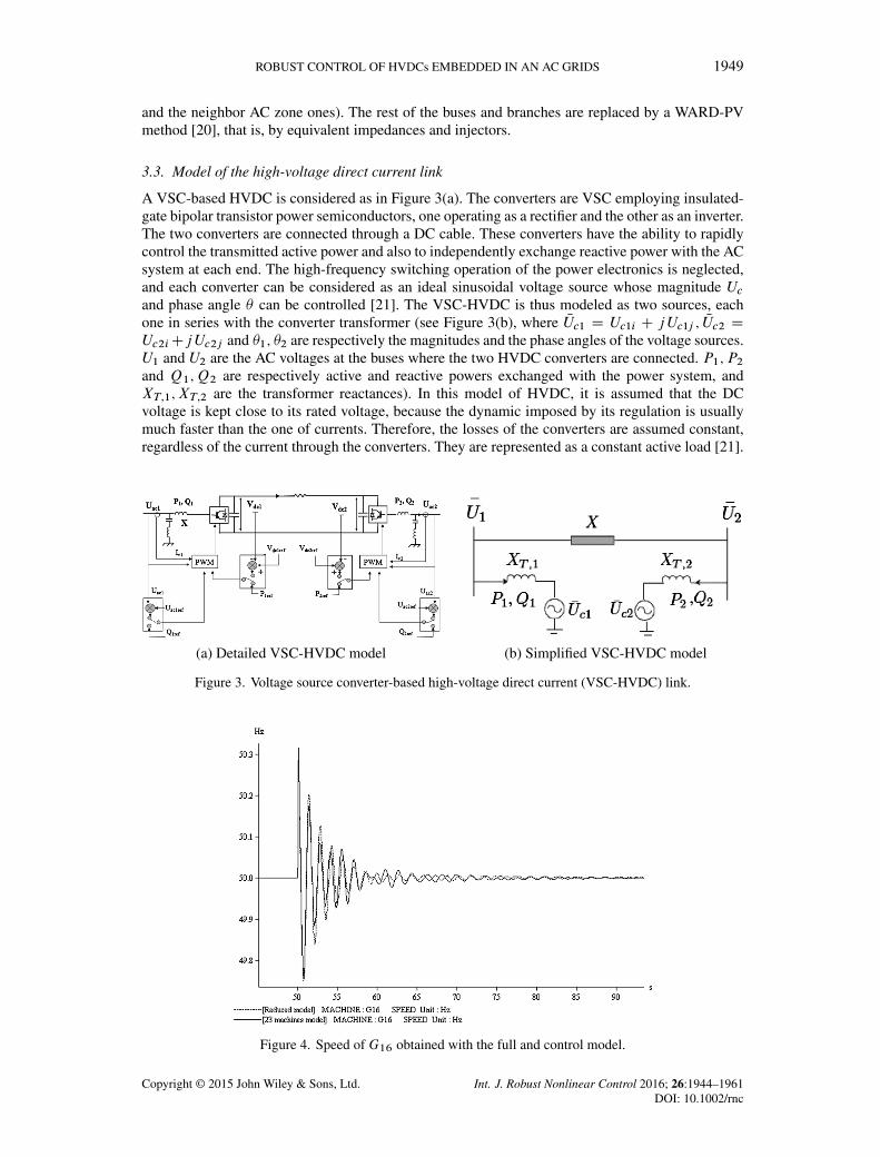
A VSC-based HVDC is considered as in Figure 3(a). The converters are VSC employing insulated-gate bipolar transistor power semiconductors, one operating as a rectifier and the other as an inverter.The two converters are connected through a DC cable. These converters have the ability to rapidlycontrol the transmitted active power and also to independently exchange reactive power with the ACsystem at each end. The high-frequency switching operation of the power electronics is neglected,and each converter can be considered as an ideal sinusoidal voltage source whose magnitude Ucand phase angle � can be controlled [21]. The VSC-HVDC is thus modeled as two sources, eachone in series with the converter transformer (see Figure 3(b), where NUc1 D Uc1i C jUc1j ; NUc2 DUc2iCjUc2j and �1; �2 are respectively the magnitudes and the phase angles of the voltage sources.U1 and U2 are the AC voltages at the buses where the two HVDC converters are connected. P1; P2and Q1;Q2 are respectively active and reactive powers exchanged with the power system, andXT;1; XT;2 are the transformer reactances). In this model of HVDC, it is assumed that the DCvoltage is kept close to its rated voltage, because the dynamic imposed by its regulation is usuallymuch faster than the one of currents. Therefore, the losses of the converters are assumed constant,regardless of the current through the converters. They are represented as a constant active load [21].
Figure 3. Voltage source converter-based high-voltage direct current (VSC-HVDC) link.
Figure 4. Speed of G16 obtained with the full and control model.
Copyright © 2015 John Wiley & Sons, Ltd. Int. J. Robust Nonlinear Control 2016; 26:1944–1961DOI: 10.1002/rnc

1950 L. ARIOUA AND B. MARINESCU
This leads to
P1 D .U1.sin �1Uc1i � cos �1Uc1j //=XT1;
Q1 D .U21 � U1.cos �1Uc1i C sin �1Uc1j //=XT1;
P2 D .U2.sin �2Uc2i � cos �2Uc2j //=XT2;
Q2 D .U22 � U2.cos �2Uc2i C sin �2Uc2j //=XT2:
(1)
In addition, notice that P2 D �P1. The control variables can be expressed as follows:
Uc1i D Uc1i0 C�Uc1i ; Uc1j D Uc1j0 C�Uc1j ;
Uc2i D Uc2i0 C�Uc2i ; Uc2j D Uc2j0 C�Uc2j :(2)
3.4. Validation of the nominal nonlinear control model
Figure 4 shows the speed response of the generatorG16 of the example considered in Section 2.2 to afault obtained with the control model (dotted line) and, respectively, with the full 23-machine model(solid line). The two curves do not completely overlap but have the same shape, which guaranteethe computation of quite similar CCTs with both models.
4. THE UNCERTAIN LINEAR CONTROL MODEL
4.1. Linear approximation of the nominal model
The control model described in Section 3 is nonlinear and can be generally represented by thenonlinear differential and algebraic equations
†NL W
²Px D f .x; U /y D g.x; U /;
(3)
where x represents the state variables (speeds, angles of machines, automatic voltage regulators,governors variables, etc.). The latter model (3) corresponds to the well-known differential-algebraicequations form used to analytically model power systems for transient stability analysis like, forexample, in [22]. The control variables U are the magnitudes of the voltage sources (Section 3.3).The outputs y are the measures of active and reactive powers usually used for the converter controls[21], and yref are the control references.This leads to U D ŒUc1i ; Uc1j ; Uc2i ; Uc2j �; y D ŒP1;Q1;Q2�; yref D ŒPref1;Qref1;Qref2�.
Let
†L W
²� Px D A�x C B�U�y D C�x
(4)
be the linear approximation of (3) around a given equilibrium point .x0; U0; y0/, where �x Dx � x0; �U D Œ�Uc1i ; �Uc1j ; �Uc2i ; �Uc2j �; �y D y � y0 and A;B;C are constant matrices.The latter linear model is used in Section 5 for the synthesis of a robust linear control.
Figure 5. Plant with multiplicative output uncertainty.
Copyright © 2015 John Wiley & Sons, Ltd. Int. J. Robust Nonlinear Control 2016; 26:1944–1961DOI: 10.1002/rnc

ROBUST CONTROL OF HVDCs EMBEDDED IN AN AC GRIDS 1951
Figure 6. Relative error versus the magnitude of Wt .
4.2. Synthesis of the uncertain model
The two kinds of topology variation associated to a fault and explained in Section 2 can be directlytaken into account in the linear approximation of the control model. Indeed, these different topolo-gies generated during different cases of short circuits constitute a family of linear control modelsP�.s/, which can be considered as an unstructured uncertainty. The control model described inSection 3 is considered as the nominal model P.s/. More specifically, Figure 6 shows the singu-lar values of the deviations .P�.s/ � P.s//P.s/�1 of all the aforementioned family of perturbedmodels with respect to the nominal one. The family of perturbed models generated is considered asan uncertain model P�.s/ with output unstructured uncertainty P�.s/ D .1C�.s/Wt .s//P.s/ asshown in Figure 5, where Wt .s/ is the uncertainty weight. The latter weight is used to capture howthe relative uncertainty varies with frequency, and it is chosen such that the maximum magnitudeof all relative error curves in Figure 6 is below this weight. �.s/ is the normalized model deviationwith respect to the nominal model.
5. A ROBUST CONTROL DESIGN
5.1. Design requirements
The regulators of the HVDC converters are generally synthesized to ensure local performances as
� tracking of references for active and reactive powers Pref1;Qref1;Qref2 or for voltages at bothends of the DC link according to the usual time setting for HVDC power control (time constantsbetween 80 and 100 ms),� possibility of inversion of the power flow in a given time (usually around 200 ms).
The control model developed earlier is used to synthesize a singular coordinated controller for bothHVDC converters. This controller has to ensure the performances cited in the preceding texts inaddition to the
� grid performances for several cases of fault (i.e., improvement of the transient stability).
Our control model includes the uncertainties that represent the different cases of critical situations(according to Section 4.2). This motivated the synthesis of a robust multivariable control.
Notice that, to avoid the use of remote variables (e.g., machines speed and angles), an outputfeedback structure is used for the control model.
Copyright © 2015 John Wiley & Sons, Ltd. Int. J. Robust Nonlinear Control 2016; 26:1944–1961DOI: 10.1002/rnc

1952 L. ARIOUA AND B. MARINESCU
Figure 7. Plant with sensitivity weights.
Thus, only variables available at converter stations are used, and a coordinated controller is devel-oped for both converters. Obviously, in case of use of remote signals, the performances of the controlloop can be improved.
5.2. A mixed sensitivity H1 control design
We use the mixed sensitivity H1 control design. The sensitivity S.s/ D .I C P.s/K.s//�1 isthe closed-loop transfer matrix from the reference inputs to the error (i.e., r 7! e in Figure 7). Thecomplementary sensitivity T .s/ D P.s/K.s/.I C P.s/K.s//�1 is the closed-loop transfer matrixfrom the references to the measured outputs (i.e., r 7! Zt in Figure 7), where P.s/ is the nominalmodel, K.s/ is the controller, and I is the identity matrix.
Let Wt .s/ be the weight used to achieve robustness against uncertainties caused by faulted sit-uations as explained in Section 2 and Ws.s/ be another weight based on the desired shape of thesensitivity in order to satisfy the performances specified in Section 5.1.Ws.s/ is chosen in the form [23]
Ws D
�s= kpMs C !b
s C !bkp"
�k; (5)
where !b is the bandwidth,Ms is the peak sensitivity, " is the steady-state error desired with respectto a step input, and k is the order of the weighting function. Notice that making " small enforces theintegral action (in our case " D 10�4).
The closed-loop system is guaranteed stable for all plants in P�.s/, if a controller K.s/, whichensures kWt .s/T .s/k1 6 1 for all frequencies, is found [24]. The desired performances areachieved if kWs.s/S.s/k1 6 1. Thus, the H1 controller K.s/ is designed to minimize thecost function:
� D
�����Ws.s/S.s/
Wt .s/T .s/
�����1
6 1: (6)
The gain � (defined by (6)) obtained is about 1.05. When the value of lambda is less or equal than1, 100% of the desired performances are achieved. However, we assume that 1.05 is acceptable,and the frequency-domain tracking performance and robustness specified before are met by thecontroller K.s/.
5.3. Computation and implementation of the controller
The multivariable robust controller K.s/ is calculated by solving an associated Ricatti equation viaa function of robust control toolbox of Matlab. The final controller is given in its state representation.AK ; BK ; CK ;DK/; and it is of the same order as the linear control model augmented by the weightsWs.s/ and Wt .s/. In the case of the example of Section 2.2, the linear control model obtained afterreduction and minimal realization is of order 30 (Appendix B). The controller obtained is of order40, which is too high for implementation. For this reason, it is a common practice to reduce theorder of the controller. A reduction method based on the singular values [23] allowed us to generatea controller of order 5. This method of reduction is based on the computation of the Hankel singular
Copyright © 2015 John Wiley & Sons, Ltd. Int. J. Robust Nonlinear Control 2016; 26:1944–1961DOI: 10.1002/rnc

ROBUST CONTROL OF HVDCs EMBEDDED IN AN AC GRIDS 1953
values of the system, which indicate the respective state energy of the system. The reduced ordercan be directly determined by examining the system Hankel singular values. The truncations havebeen performed with an existing function in robust control design toolbox of Matlab named reduce.
6. SIMULATION TESTS
This section deals with the validation of the proposed controller. In fact, simulation tests usingthe EUROSTAG software (Tractebel Engineering, Brussels, Belgium and Réseau de Transportd’Electricité (RTE) - France) [22] are performed with both the 23-machine benchmark (Section 2.2)and a second one based on realistic large-scale model of the European power system. Notice thatEUROSTAG is a software developed for accurate and reliable simulations of power system dynam-ics. It is used for the dynamic phenomena with time constants in the range from few milliseconds toa few seconds. It mainly concerns the problems of stability of groups in case of faults.
6.1. Description of the alternative controls
The new controller is compared with two other controllers. The first one is the standard vectorcontroller, usually used in power systems for the control of power electronics (e.g., [25]). The pro-portional and integral gains of this control are synthesized using standard criteria for electrical drivesto satisfy the performances specified in Section 5.2. The second controller is a coordinated optimallinear quadratic (LQ) controller (e.g., [26]); we have synthesized on the base of the linearized nom-inal model described in Section 3. The three controllers are tuned to satisfy almost the same localperformance specifications. As a consequence, the robustness level they provide can be directlycompared.
In what follows, the three controllers mentioned earlier are first tested on the 23-machine exampleof Section 2.2.
6.2. Local performances
An export of 1000 MW is considered from France to Spain via the HVDC link. To test local perfor-mances, a�0:1-pu step is applied to the reference of the active power transmitted through the HVDClink .Pref1/. Figure 8 shows the responses of the active power. It can be noticed a good tracking ofthe active power reference and time constants compliant with the specifications given in Section 5.2.In addition, one can remark that the three controllers provide almost the same closed-loop dynamics.
Figure 8. Response of P1 to a �0:1-pu step on Pref1.
Copyright © 2015 John Wiley & Sons, Ltd. Int. J. Robust Nonlinear Control 2016; 26:1944–1961DOI: 10.1002/rnc

1954 L. ARIOUA AND B. MARINESCU
6.3. Transient stability
Figure 9(a) and (b) presents the active and reactive power responses to a symmetrical short circuitof 100 ms occurring near the converter 1 (French side). It can be seen better dynamic responses withthe new H1 controller. In fact, a lower time of recovering after the fault and a lower overshootare observed. This leads to less severe saturation in operation in comparison with the standard one.Furthermore, Figure 10(a) and (b) shows that the transient oscillations obtained with the H1 andthe LQ controllers are more damped than the ones obtained with the standard vector control.
In addition to the simulations presented earlier, the CCTs obtained with the three controllers werecompared in Table V. A difference up to 15% is observed between the use of the new controller and
Figure 9. Active and reactive power responses to a 100-ms short circuit in case of 1000-MW power export.
Figure 10. Machine responses to a short circuit in case of power export.
Table V. Critical clearing time validation of the new controller.
Location of Standard controller LQ controller New controllerthe fault CCT [ms] CCT [ms] CCT [ms]
Llogaia 245 277 284Vic 223 249 255Bescano 212 239 246Vandellos 127 130 137Braud 138 140 161
CCT, critical clearing time; LQ, linear quadratic.
Copyright © 2015 John Wiley & Sons, Ltd. Int. J. Robust Nonlinear Control 2016; 26:1944–1961DOI: 10.1002/rnc

ROBUST CONTROL OF HVDCs EMBEDDED IN AN AC GRIDS 1955
Figure 11. Active and reactive power responses to a 100-ms short circuit in case of 600-MW power import.
Figure 12. Insertion of the Midi-Provence high-voltage direct current (HVDC) link in the Europeaninterconnected power system.
the LQ controller and up to 23% between the new controller and the standard one. This confirms theimprovement of transient stability in the case of the new robust H1 controller in comparison withthe two other controllers.
6.4. Robustness against the variation of operating point
The robust proposed controller was synthesized using a linearized model. This conducts us to per-form some additional tests of robustness of performances against the variation of the operating point.A new situation of load flow is considered for the simulations. The import from Spain to Franceis 600 MW in this case. Notice that the same controllers as before are used, that is, the ones syn-thesized using the export situation. Figure 11(a) and (b) gives the active power and reactive powerresponses to 100-ms short circuit applied near the converter 2 (Spanish side). Both are comparablewith the ones obtained when the export scenario is used (Figure 9(a) and (b)). Moreover, in this sit-uation also, the responses are better than the ones obtained with the standard and LQ controllers.This confirms the good robustness of the performances of the proposed controller against variationof operating conditions.
Copyright © 2015 John Wiley & Sons, Ltd. Int. J. Robust Nonlinear Control 2016; 26:1944–1961DOI: 10.1002/rnc

1956 L. ARIOUA AND B. MARINESCU
Figure 13. Responses to a 100-ms Tavel–Tamareau short circuit.
Table VI. Critical clearing time validation for the real European system.
Fault simulated Standard controller CCT [ms] Robust controller CCT [ms]
Darse-Feuillane 216 224Feuillane-Ponteau 192 204Ponteau-Feuillane 183 195Ponteau-Realtor 181 192Feuillane-Lavera 194 205
CCT, critical clearing time.
6.5. Tests on a realistic large-scale model of the European power system
The methodology developed in this paper was also applied to a realistic large-scale model of theEuropean power system. This model is the one mentioned at the beginning of Section 3, and it isgenerally used for interconnection and reinforcement studies by the European TSOs. It is a detailednonlinear model including generators along with their regulations (automatic voltage regulators,power system stabilizer, and governors) and where the high voltage network (225 and 400 kV)is modeled. It consists of 1121 generators, 7625 nodes, 10,404 lines, 2550 transformers, and458-GVA global apparent power. Also, a real reinforcement situation has also been considered. Anew HVDC link of 230-km length and 1000-MW power capacity is placed as shown in Figure 12and according to Midi-Provence project [27]. The objective is to control this DC link.
As before, the new H1 controller obtained in this case is compared with the standard vectorcontroller. Figure 13(a) and (b) give the responses of active and reactive powers to a symmetricalshort circuit applied at one of the HVDC terminals in the Fos area (Figure 12), cleared after 100 ms.One can observe, as for the previous France–Spain case, that the dynamic behavior is better withthe new controller also on this new large-scale benchmark. This is confirmed by the analysis of thetransient stability of the zone. In fact, Table VI shows that the CCT is augmented when the newcontrol is used.
7. CONCLUSION
A new method for synthesizing the controllers of HVDC converters was proposed in this paper. Itis based on the use of an enriched control model that takes into consideration the dynamics thatimpact the stability of the neighbor zone of the link. In particular, a new type of interaction ofdistant machines was put into evidence by defining electrical coupling modes. These dynamics arecaptured by both linear and nonlinear considerations. To take advantage from the robust theory,the topology variations, which correspond to the main dynamics of the control model, have been
Copyright © 2015 John Wiley & Sons, Ltd. Int. J. Robust Nonlinear Control 2016; 26:1944–1961DOI: 10.1002/rnc
ROBUST CONTROL OF HVDCs EMBEDDED IN AN AC GRIDS 1957
treated as uncertainties in anH1 synthesis. However, other kinds of control, even nonlinear, can beenvisaged. From this point of view, the methodology presented here is an open control framework,which allows to
� directly take into account the neighbor zone of the HVDC link considering the dynamics thatare stringent for the transient stability and thus improve the latter,� coordinate the control actions of the two converters,� obtain better performances than the standard controllers.
The synthesis of the control model and of the regulator is implementable in a large scale. This wasproven in the paper by treating a concrete actual European grid reinforcement case. Moreover, thisframework is adequate for the coordination of the control action of several close HVDC links or ofthe latter with other actuators like generators. This point will be treated in a forthcoming work.
APPENDIX A: SOLUTION OF THE H1 CONTROL PROBLEM
A.1. The system’s representation
The stationary linear system can be given by its state representation:²Px.t/ D Ax.t/C Bu.t/y.t/ D Cx.t/CDu.t/:
(A.1)
The transfer matrix of this system is
P.s/ D C.sI � A/�1B CD (A.2)
and is noted P D
�A B
C D
�.
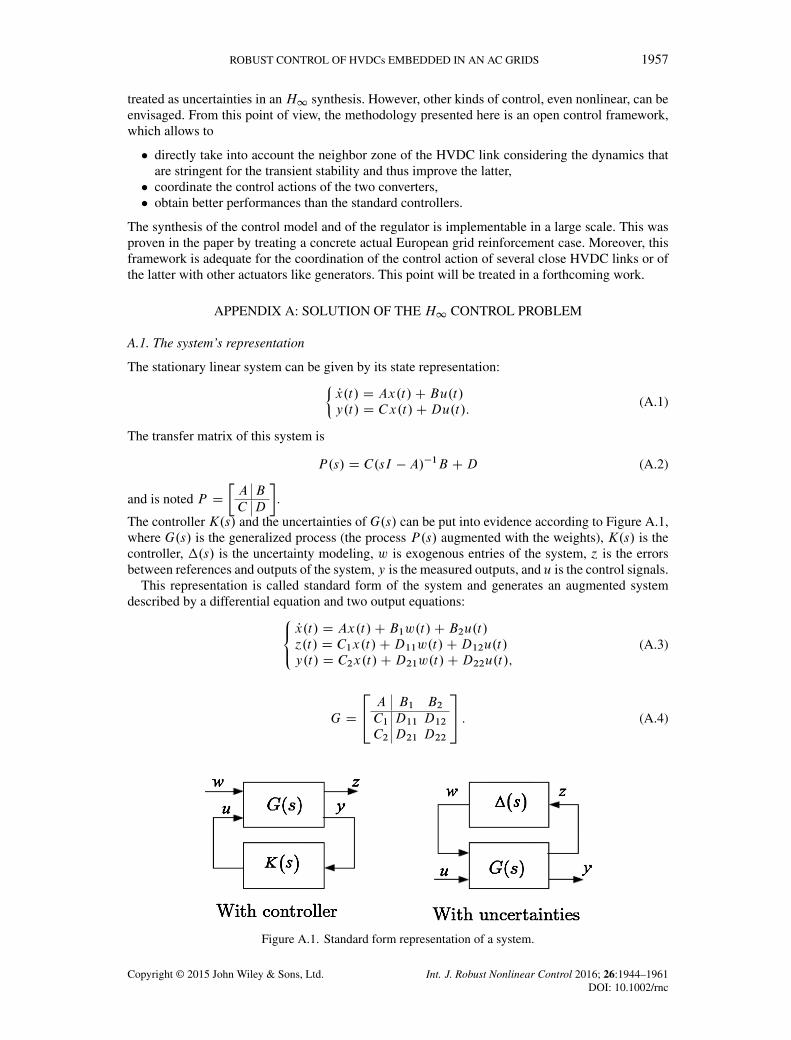
The controller K.s/ and the uncertainties of G.s/ can be put into evidence according to Figure A.1,where G.s/ is the generalized process (the process P.s/ augmented with the weights), K.s/ is thecontroller, �.s/ is the uncertainty modeling, w is exogenous entries of the system, ´ is the errorsbetween references and outputs of the system, y is the measured outputs, and u is the control signals.
This representation is called standard form of the system and generates an augmented systemdescribed by a differential equation and two output equations:8<
:Px.t/ D Ax.t/C B1w.t/C B2u.t/´.t/ D C1x.t/CD11w.t/CD12u.t/y.t/ D C2x.t/CD21w.t/CD22u.t/;
(A.3)
G D
24 A B1 B2C1 D11 D12C2 D21 D22
35 : (A.4)
Figure A.1. Standard form representation of a system.
Copyright © 2015 John Wiley & Sons, Ltd. Int. J. Robust Nonlinear Control 2016; 26:1944–1961DOI: 10.1002/rnc

1958 L. ARIOUA AND B. MARINESCU
The transfer matrixG.s/ of this augmented system can be partitioned according to the inputs/outputs
G.s/ D
�G11.s/ G12.s/
G21.s/ G22.s/
�: (A.5)
A.2. Problem formulation
The plant G has two inputs, the exogenous input w, which includes reference signal and distur-bances; and the control variables u. There are two outputs, the error signals ´, which we want tominimize; and the measured variables y, which we use to control the system. y is used in K tocalculate the control variable u.
It is possible to express the dependency of ´ on w as ´ D Fl.P;K/w,
Fl.P;K/ D G11 CG12K.I �G22K/�1G21; (A.6)
called the lower linear fractional transformation.The objective of the H1 control design is to find a controller K, which stabilizes the closed loop
for all the plants in the family P�.s/ and such that Fl.P;K/ is minimized according to the H1norm. The infinity norm of the transfer function matrix is defined askFl.P;K/k1 D sup
!N�.Fl.P;K/.j!//, where N� is the maximum singular value of the matrix
Fl.P;K/.j!/.Because theH1 norm to be minimized is a superior value over ! of the maximum singular valueN� of the transfer Fl.P;K/.j!/, this allows us to develop a controller that takes into considerationthe worst-case situation.
Notice that the singular values are used for in the case of multivariable systems to represent themodel gains over all input and output directions.
A.3. Solution of the H1 control problem
Consider the generalized state representation described by (A.3) and (A.4) and its transfer matrixgiven by (A.5). We assume that D22 D 0. That is, it does not exist any direct transmission from theinput to the output.
The solution of the problem is based on the solution of the algebraic Riccati equation as it isdetailed in the Appendix A,
XE CETX �XWX CQ D 0; (A.7)
with W D W T and Q D QT .A stabilizing solution X of (A.7), if it exists, is a symmetrical matrix such that .E-WX/ is a
stable matrix (eigenvalues with strictly negative real parts). This solution is noted:
X D Ric
�E �W
�Q �ET
�: (A.8)
The solution of the Riccati equation is as follows:
Let be Rn D DT1�D1� �
��2Im1 0
0 0
�and QRn D D�1DT
�1 �
��2Ip1 0
0 0
�,
where D1� D�D11 D12
�and D�1 D
�D11D21
�.
Because Rn and QRn are not singular, we define the two Hamiltonian matrices
H D
�A 0
�C T1 C1 �AT
��
�B
�C T1 D1�
�R�1n
�DT1�C1 BT
�; (A.9)
J D
�AT 0
�B1BT1 �A
��
�C T
�B1DT�1
�QR�1n
�D�1B1
T C�: (A.10)
Copyright © 2015 John Wiley & Sons, Ltd. Int. J. Robust Nonlinear Control 2016; 26:1944–1961DOI: 10.1002/rnc

ROBUST CONTROL OF HVDCs EMBEDDED IN AN AC GRIDS 1959
If we put X D Ric.H/ and Y D Ric.J /, we can define the two matrices
F D �R�1nDT1�C1 C B
TXD
�F1F2
�D
24F11F12F2
35 ; (A.11)
L D �B1D
T�1 C YC
TQR�1n D
�L1 L2
�D�L11 L12 L2
�; (A.12)
where F1; F2; F11, and F12 are formed respectively by m1, m2, m1 � p2, and p2 lines and L1, L2,L11, and L12 are formed respectively by p1, p2, p1 �m2, and m2 columns.A solution exists if the two following conditions are satisfied:
� .A;B2/ is stabilizable, and .C2; A/ is detectable;
� D12 D
�0
Im2
�and D21 D
�0 Ip2
�are then respectively of rank m2 and p2;
� 8! 2 R rang
�A � j!In B2
C1 D12
�D nCm2; then this matrix is of full rank; in addition, P12
has no invariant zeros on the imaginary axis;
� 8! 2 Rrang
�A � j!In B1
C2 D21
�D nC p2; then this matrix is of full rank; in addition, P21
has no invariant zeros on the imaginary axis.
Let D11 D
�D1111 D1112D1121 D1122
�with D1122 is of dimension m2 � p2; the solution will be given by
the following theorem :
Theorem 1If a system G.s/ verifies the hypotheses 1–4 described earlier, then
(a) it exists a controller K.s/; which stabilizes the closed loop and such that kFl.P;K/k1 < �if and only if
1. � > max. N�ŒD1111 D1112�; N�ŒD1111 D1121�/;2. it exists solutions X > 0 and Y > 0, which verify the two Riccati equations relating
to Hamiltonians matrices H and J and such that �.XY / < �2, where �.:/ designs thespectral radius.
(b) If the conditions of part (a) are satisfied, then the controllers, which stabilize the system andwhich verify kFl.P;K/k1 < � , are given by
K.s/ D Fl.M; /; (A.13)
where k.s/k1 < � and
M D
24OA OB1 OB2OC1 OD11 OD12OC2 OD21 0
35 (A.14)
and
OD11 D �D1121DT1111
�2Im1�P2 �D1111D
T1111
�1D1112 �D1122
OD12 2 Rm2�m2 and OD21 2 Rp2�p2 are two arbitrary matrices that verify
OD12 ODT12 D Im2 �D1121
�2Im1�P2 �D
T1111D1111
�1DT1121
ODT21OD21 D Ip2 �D
T1121
�2Ip1�m2 �D1111D
T1111
�1D1121
OB2 D Z.B2 C L12/ OD12 and OB1 D �ZL2 CZ.B2 C L12/ OD11OC2 D � OD21.C2 C F12/ and OC1 D F2 � OD11.C2 C F12/
Z D .In � ��2YX/�1
OA D AC BF � OB1.C2 C F12/:
Copyright © 2015 John Wiley & Sons, Ltd. Int. J. Robust Nonlinear Control 2016; 26:1944–1961DOI: 10.1002/rnc

1960 L. ARIOUA AND B. MARINESCU
The controller calculated for .s/ D 0 is called the central corrector; it is generally used underthe form
K.s/ D
�OA OB1OC1 OD11
�: (A.15)
APPENDIX B: FORM OF THE CONTROL MODEL P(S)
P11.s/D814:6s28C2:448106s27C2:458109s26C8:281011s25C4:771012s24C1:71014s23C8:021014s22
s29C1006s28C6:02106s27C14:036109s26C1:0231012s25C6:091012s24C2:11014s23C1:011015s22C1:811016s21
1:461016s21C8:921016s20C7:0391017s19C2:4561018s18C2:0741019s17C6:2791019s16C3:931020s15C1:931021s14C4:851021s13
7:421016s20C8:691017s19C3:071018s18C2:561019s17C7:8451019s16C4:81020s15C1:281021s14
1:081022s12C3:871022s11C7:241022s10C1:931023s9C2:8941023s8C5:6071023s7C6:2121023s6C8:411023s5C5:791023s4C5:121023s3
61021s13C1:3581022s12C4:7811022s11C9:071022s10C2:371023s9C3:621023s8C6:871023s7C7:761023s6C1:021024s5C7:1541023s4C6:11023s3
1:771023s2C6:631022sC7:251021
2:091023s2C7:491022sC2:611021.
ACKNOWLEDGEMENTS
The authors would like to thank Prof. Eric Monmasson, University of Cergy-Pontoise; Dr Alexandre Parisot,head of Integration of New Technology division (INT) of RTE; and Patrick Panciatici, scientific advisor atRTE-DES, for the helpful suggestions and remarks.
REFERENCES
1. Hingorani GN, Gyugyi L. Understanding FACTS: Concepts and Technology of Flexible AC Transmission Systems.IEEE Press: Piscataway, 2000.
2. Goodrich F, Andersen B. The 2000 MW HVDC link between England and France. Power Engineering Journal 1987;1(2):69–74.
3. Hauer JF. Robustness issues in stability control of large electric power systems. Proceedings of 32nd IEEEConference on Decision and Control, San Antonio, Texas, 1993; 2329–2334.
4. Vovos NA, Galanos GD. Enhancement of the transient stability of integrated AC/DC systems using active and reactivepower modulation. IEEE Power Engineering Review 1985; 5(7):33–34.
5. Smed T, Andersson G. Utilizing HVDC to damp power oscillations. IEEE Transactions on Power Delivery 1993;8(2):620–627.
6. Hammad AE, Gagnon J, McCallum D. Improving the dynamic performance of a complex AC/DC system by HVDCcontrol modifications. IEEE Transactions on Power Delivery 1990; 5(5):1934–1943.
7. Shun FL, Muhamad R, Srivastava K, Cole S, Hertem DV, Belmans R. Influence of VSC HVDC on transient stability:case study of the Belgian grid. Proceedings of IEEE Power and Energy Society General Meeting, Minneapolis, USA,2010; 1–7.
8. Taylor CW, Lefebvre S. HVDC controls for system dynamic performance. IEEE Transactions on Power Systems1991; 6(2):743–752.
9. Hu Z, Mao C, Lu J. Improvement of transient stability in AC system by HVDC Light. Proceedings of Transmissionand Distribution Conference and Exhibition IEEE, Dalian, 2005; 1–5.
10. Mao C, Hu Z, Lu J, Chang D, Fan S. Application of an optimal coordinated control strategy to VSC HVDC.Proceedings of Power Systems Conference and Exposition IEEE, Atlanta, 2006; 2141–2145.
11. To K, David A, Hammad A. A robust co-ordinated control scheme for HVDC transmission with parallel AC systems.IEEE Transactions on Power Delivery 1994; 9(3):1710–1716.
12. Latorre H, Ghandhari M. Improvement of power system stability by using a VSC-HVDC. International Journal ofElectrical Power & Energy Systems 2011; 33(2):332–339.
13. Fuchs A, Imhof M, Demiray T, Morari M. Stabilization of large power systems using VSC-HVDC and modelpredictive control. IEEE Transactions on Power Delivery 2014; 29(1):480–488.
14. Rostamkolai N, Phadke AG, Long WF, Thorp JS. An adaptative optimal control strategy for dynamic stabilityenhacement of AC/DC power systems. IEEE Transactions on Power Systems 1988; 3(3):1139–1145.
15. Kundur P. Power Stability and Control. McGraw-Hill: New York, 1994.16. Aouini R, Ben Kilani K, Marinescu B, Elleuch M. Improvement of fault critical time by HVDC transmission. In
Proceedings of Systems, Signals and Devices, Sousse, Tunisia, 2011; 1–6.17. Ramaswamy GN, Verghese GC, Rouco L, Vialas C, Demarco CL. Synchrony, aggregation and multi-area eigenanal-
ysis. IEEE Transaction on Power Systems 1995; 10(4):1986–1993.18. Luther M, Biernaka I, Preotescu D. Feasibility aspects of a synchronous coupling of the IPS/UPS with the UCTE.
Water and Energy International 2012; 69(3):62-62.19. Breulmann H, Grebe E, L?sing M. Analysis and damping of inter-area oscillations in the UCTE/CENTREL power
system. CIGRE Session, Paris, 2000; 38–113.
Copyright © 2015 John Wiley & Sons, Ltd. Int. J. Robust Nonlinear Control 2016; 26:1944–1961DOI: 10.1002/rnc

ROBUST CONTROL OF HVDCs EMBEDDED IN AN AC GRIDS 1961
20. Baldwin TL, Mili L, Phadke AG. Dynamic ward equivalents for transient stability analysis. IEEE Transactions onPower Systems 1994; 9(1):59–67.
21. Latorre HF, Ghandhari M, Söder L. Active and reactive power control of a VSC-HVDC. Electric Power SystemsResearch 2008; 78(10):1756–1763.
22. Meyer B, Stubbe M. EUROSTAG, a single tool for power system simulation. Transmission & DistributionInternational, Brussels, Belgium, 1992; 47–52.
23. Zhou K, Doyle JC. Essentials of Robust Control. Prentice Hall: New Jersey, 1997.24. Skogestad S, Postlethwaite I. Multivariable Feedback Control. John Wiley: Chichester, 1996.25. Li S, Haskew TA, Xu L. Control of HVDC light system using conventional and direct current vector control
approaches. IEEE Transactions on Power Electronics 2010; 25(12):3106–3118.26. Kwakernaak H, Sivan R. Linear Optimal Control systems. John Wiley: New York, 1972.27. Schéma décennal de développement du réseau, 2013. (Available from: http://www.rte-france.com/).
Copyright © 2015 John Wiley & Sons, Ltd. Int. J. Robust Nonlinear Control 2016; 26:1944–1961DOI: 10.1002/rnc