robust control in a multimachine power system using adaptive neuro-fuzzy stabilisers
TRANSCRIPT
MODERN ELECTRIC POWER SYSTEMS
Robust control in a multimachine power systemusing adaptive neuro-fuzzy stabilisers
Z. Barton
Abstract: A robust artificially intelligent adaptive neuro-fuzzy power system stabiliser (ANF PSS)design for damping electromechanical modes of oscillations and enhancing power systemsynchronous stability is presented. An actual power system is decomposed into separatesubsystems, each subsystem consisting of one machine. The local ANF PSS is associated with eachsubsystem. The local feedback controllers rely only on information particular to their subsystem.The input signals are the speed, power angle and real power output. Nonlinear simulations showthe robustness of the ANF PSS.
1 Introduction
Analogue-type power system stabilisers [1, 2] commonlyknown as PSSs, have been widely used for the enhancementof overall power system (PS) stability during the last twentyyears. The fundamental function of a PSS is to add asupplementary control signal to the excitation control loopso as to increase the damping of generator oscillations. Inthe installation of such a conventional PSS (CPSS) to agenerator, all the CPSS parameters are fixed to ensure theoptimal performance of the installed CPSS at a specificoperating point of the unit. Therefore, the CPSS perfor-mance is degraded whenever the operating point changesfrom the specific point to another point because of the fixedparameters. To overcome the disadvantages of the CPSS,microcomputer-based digital-type PSSs, such as the self-tuning PSS [3, 4], rule-based PSS [5] and fuzzy logic PSS [6,7] have been proposed, and encouraging results have beenobtained.
In recent years, new artificial intelligence-based ap-proaches have been proposed to improve CPSS. Theseapproaches include the online training neuro-fuzzy inferencesystem we found among other things in [8, 9].
This paper investigates the robustness of an adaptiveneuro-fuzzy power system stabiliser (ANF PSS) [10] usingthe speed/acceleration state of the study unit. The proposedstabiliser is composed of a fuzzy controller transformer andan adaptive neural network. The desired controller in thiscase has been chosen as the adaptive neuro-fuzzy inferenceSugeno-type system (ANFIS) [11, 12]. Speed deviation,rotor angle and electrical power are chosen as the inputsignals to the neuro-fuzzy controller. The measured signalsare the real power output and/or the speed of the study unit.From the measurements, the speed/acceleration state of thestudy unit is introduced, and a desired stabilising signal isderived from the state according to pre-specified fuzzy logiccontrol rules. The ANFIS generates supplementary controlsignals to conventional controllers and works adaptively in
response to changes in operating conditions and networkconfiguration. The supplementary stabilising signals to theprimary controller are utilised to improve damping of theelectromechanical oscillations and to control the excitation.The control rules are quite simple so as to avoid a heavycomputational burden. This is essential when consideringthe real time control of the study unit.
The problem of the modes of the PS oscillations is not theaim of these experiments. Instead, the goal is simply toshow the great potential of the ANF PSS in increasing thedamping of the generator oscillations.
Nonlinear simulations show the robustness of theproposed ANF PSS subject to a wide range of loadingconditions. A seven-machine system is used as a modelmultimachine system. Comparison studies are also madebetween the ANF PSS and the CPSS installed at the all sub-area. The results indicate the advantages of the proposedANF PSS. Experimental results are also presented briefly todemonstrate the efficiency of the ANF PSS as applied to amultimachine system.
2 Multi-input ANF PSS
2.1 Power system modelThe system studied consists of seven-synchronous genera-tors connected to a load bus through an AC network. Thegenerating units are modelled by the elements of the powersystem blocksets [12, 13].
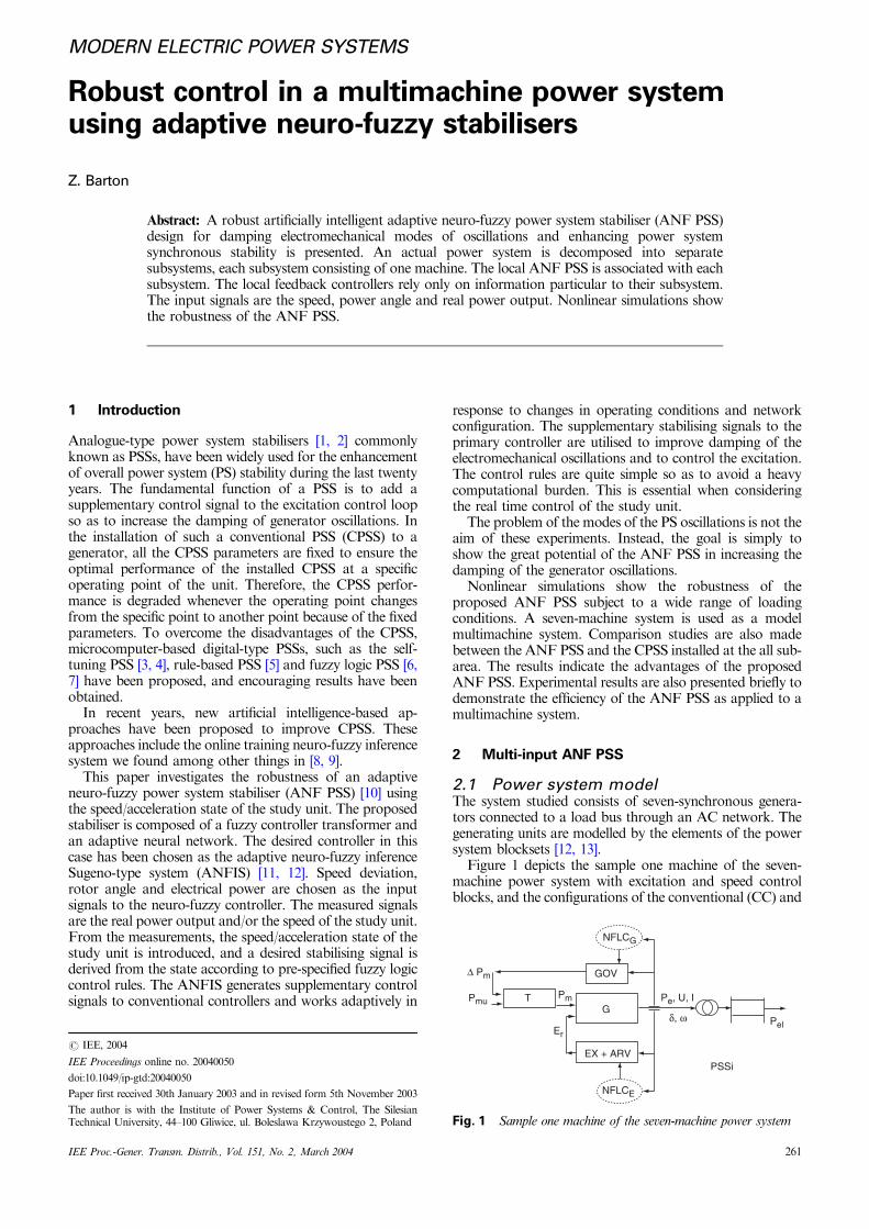
Figure 1 depicts the sample one machine of the seven-machine power system with excitation and speed controlblocks, and the configurations of the conventional (CC) and
∆ Pm
PmuPmT
Er
G
NFLCG
NFLCE
GOV
Pe, U, I
δ, ω Pel
PSSiEX + ARV
Fig. 1 Sample one machine of the seven-machine power systemThe author is with the Institute of Power Systems & Control, The SilesianTechnical University, 44–100 Gliwice, ul. Boleslawa Krzywoustego 2, Poland
r IEE, 2004
IEE Proceedings online no. 20040050
doi:10.1049/ip-gtd:20040050
Paper first received 30th January 2003 and in revised form 5th November 2003
IEE Proc.-Gener. Transm. Distrib., Vol. 151, No. 2, March 2004 261
neuro-fuzzy logic controllers (NFLC) structure. Thesynchronous generator is equipped with an automaticvoltage regulator (AVR), exciter (EX) and governor(GOV), which are responsible for keeping the generatoroutput voltage and power under operating conditions atvarious load levels [14]. The model takes into account thedynamics of the stator, field and damper windings. Theequivalent circuit of the model is represented in the rotorreference frame (qd frame). The electrical part of themachine is represented by a sixth-order state-space modeland the mechanical part is the same as in the simplifiedsynchronous machine block. The steam turbine andgovernor block (GOV) implements a complete tandem-compound steam prime mover, including a speed governingsystem, a four-stage steam turbine, and a shaft with up tofour masses. The steam turbine has four stages, eachmodelled by a first-order transfer function.
2.2 Adaptive neuro-fuzzy stabiliserOnce a fuzzy controller is transformed into an adaptivenetwork, the resulting ANFIS can take advantage of all theneural network (NN) controller design techniques proposedin the literature [11].
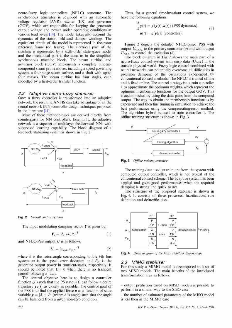
Most of these methodologies are derived directly fromcounterparts for NN controllers. Essentially, the adaptivenetwork is a superset of multilayer feedforward NNs withsupervised learning capability. The block diagram of afeedback stabilising system is shown in Fig. 2.
The input modulating damping vector Y is given by:
Y i ¼ ½di;oi; Pei�T ð1Þ
and NFLC-PSS output U is as follows:
U i ¼ ½unfli; ugnfli�T ð2Þ
where d is the rotor angle corresponding to the i-th bussystem, o is the speed error deviation and Pe, is thegenerator output power in transient-states, respectively. Itshould be noted that Ui¼ 0 when there is no transientperiod following a fault.
The control objective here is to design a controllerfunction g(.) such that the PS state yðtÞ can follow a desiretrajectory ydðtÞ as closely as possible. The control goal ofthe PSS is to find the applied force u as a function of statevariable y ¼ ½d;o; P � (where d is angle) such that the anglecan be balanced from a given non-zero condition.
Thus, for a general time-invariant control system, wehave the following equations:
ddt
yðtÞ ¼ f ðyðtÞ; uðtÞÞ ðPSS dynamicsÞ;
uðtÞ ¼ gðyðtÞÞ ðcontrollerÞ:ð3Þ
Figure 2 depicts the detailed NFLC-based PSS withoutput UGNFL to the primary controller (a) and with outputUNFL to control the excitation (b).
The block diagram in Fig. 2 shows the main part of aneuro-fuzzy control system with crisp data (UNFL) in theoutside physical world. Fuzzy logic control combined withneural networks can potentially overcome all difficulties inprecision damping of the oscillations experienced byconventional control methods. The NFLC is trained offlineand is fixed online. The control strategy is to train controller1 to approximate the optimum weights, which represent theoptimum membership functions for the output GOV. Thisis accomplished by using the data pairs from the computedoutput. The way to obtain the membership functions is byexperience and then fine tuning in simulation to achieve thebest performance using the compensating-error method.The algorithm hybrid is used to train controller 1. Theoffline training structure is shown in Fig. 3.
The training data used to train are from the system withcomputed output controller, which is not typical of theconventional control scheme. The adaptive system has beenapplied and gives good performances when the requireddamping is strong and quick to act.
The structure of the proposed stabiliser is shown inFig. 4. It consists of three processes: fuzzification, ruledefinition and defuzzification.
2.3 MIMO stabiliserFor this study a MIMO model is decomposed to a set oftwo MISO models. The main benefits of the introducedtransformation area as follows:
– output prediction based on MISO models is possible toperform in a similar way to the SISO case
– the number of estimated parameters of the MISO modelis less then in the MIMO case
X
X
NFLCG
NFLCE
ω
ωrefdω/dt
UGNFL
UNFL
UPSS
GOV turbinePm
feedback
feedback
Vt
Vref
Ef
EX + ARV
a
b
Fig. 2 Overall control systems
X
neuro-fuzzy controller I
training algorithm
desired controller
YD
eY
Y
Fig. 3 Offline training structure
UPSSNFLdefuzzification
HPHP
PP
Z PZ P
ZZ
Z NZ N
NN
H NH N
if - then
rules
fuzzification
δ
∆ ∞
PE
Fig. 4 Block diagram of the fuzzy stabiliser Sugeno-type
262 IEE Proc.-Gener. Transm. Distrib., Vol. 151, No. 2, March 2004
– the structure considerably simplifies MIMO implementa-tion.
The structure of the MISO stabiliser is shown in Fig. 5[10, 12, 13].
2.4 ANFIS controllerThe fuzzy models under the framework of adaptivenetworks, which possess certain advantages over neuralnetworks, are called an adaptive-network-based fuzzyinference system (ANFIS) [11]. The essential part ofan adaptive neuro-fuzzy stabiliser is an ANFIS. TheANFIS is taking a fuzzy inference system (FIS) and tuningit with a back propagation (or hybrid) algorithm basedon some collection of input-output data. Fuzzy inference isthe process of formulating the mapping from a giveninput to an output using fuzzy logic. The mapping thenprovides a basis from which decisions can be made,or patterns discerned. The process of fuzzy inferenceinvolves all of the pieces that are described below:membership functions, fuzzy logic operators, and if-thenrules. This allows the fuzzy system to learn. The basicconfiguration of a process design comprise four principlecomponents: defining input and control variables, preparinga training data set, obtaining the input and output FIS
matrix, and realising the learning process. The output FISmatrix is supplied for the stabiliser. The ANFIS is used togenerate supplementary control signals to conventionalcontrollers.
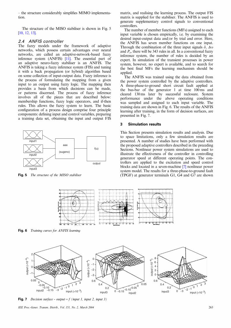
The number of member functions (MFs) assigned to eachinput variable is chosen empirically, i.e. by examining thedesired input-output data and/or by trial and error. Here,the ANFIS has seven member functions on one input.Through the combination of the three input signals d, Doand Pe, there will be 343 rules in all. In a conventional fuzzyinference system, the number of rules is decided by anexpert. In simulation of the transient processes in powersystem, however, no expert is available, and to search forthe best final MFs the learning mechanism should beapplied.
The ANFIS was trained using the data obtained fromthe power system controlled by the adaptive controllers.A three-phase-to-ground short circuit fault applied atthe bus-bar of the generator 1 at time 100 ms andcleared 130 ms later by successful reclosure. Systemperformance under the above operating conditionswas sampled and assigned to each input variable. Thetraining data are shown in Fig. 6. The results of the ANFISlearning after training, in the form of decision surfaces, arepresented in Fig. 7.
3 Simulation results
This Section presents simulation results and analysis. Dueto space limitations, only a few simulation results arepresented. A number of studies have been performed withthe proposed adaptive controllers described in the precedingSections. Nonlinear power system simulations are used toillustrate the effectiveness of the controller in controllinggenerator speed at different operating points. The con-trollers are applied to the excitation and speed controlblocks and located in a seven-machine [7] nonlinear powersystem model. The results for a three-phase-to-ground fault(TPGF) at generator terminals G1, G4 and G7 are shown
input3
input2
input1
aaa
(sugeno)f(u)
output
Fig. 5 The structure of the MISO stabiliser
2
1
0
−1
0.050−0.05
−0.10−0.15 −3 −2 −1 0 1 2 3
0
−1
−2
−3
0.60.4
0.20 −0.15
−0.10−0.05
00.05
8
6
4
2
0
0.60.4
0.20 −3 −2 −1
0 1 2 3
input (×10−3)input (×10−3)
outp
ut (
×10−4
)
outp
ut (
×10−4
)
outp
ut (
×10−4
)
input3input3input2
input2
Fig. 7 Decision surface - output¼ f (input 1, input 2, input 3)
Fig. 6 Training curves for ANFIS learning
IEE Proc.-Gener. Transm. Distrib., Vol. 151, No. 2, March 2004 263
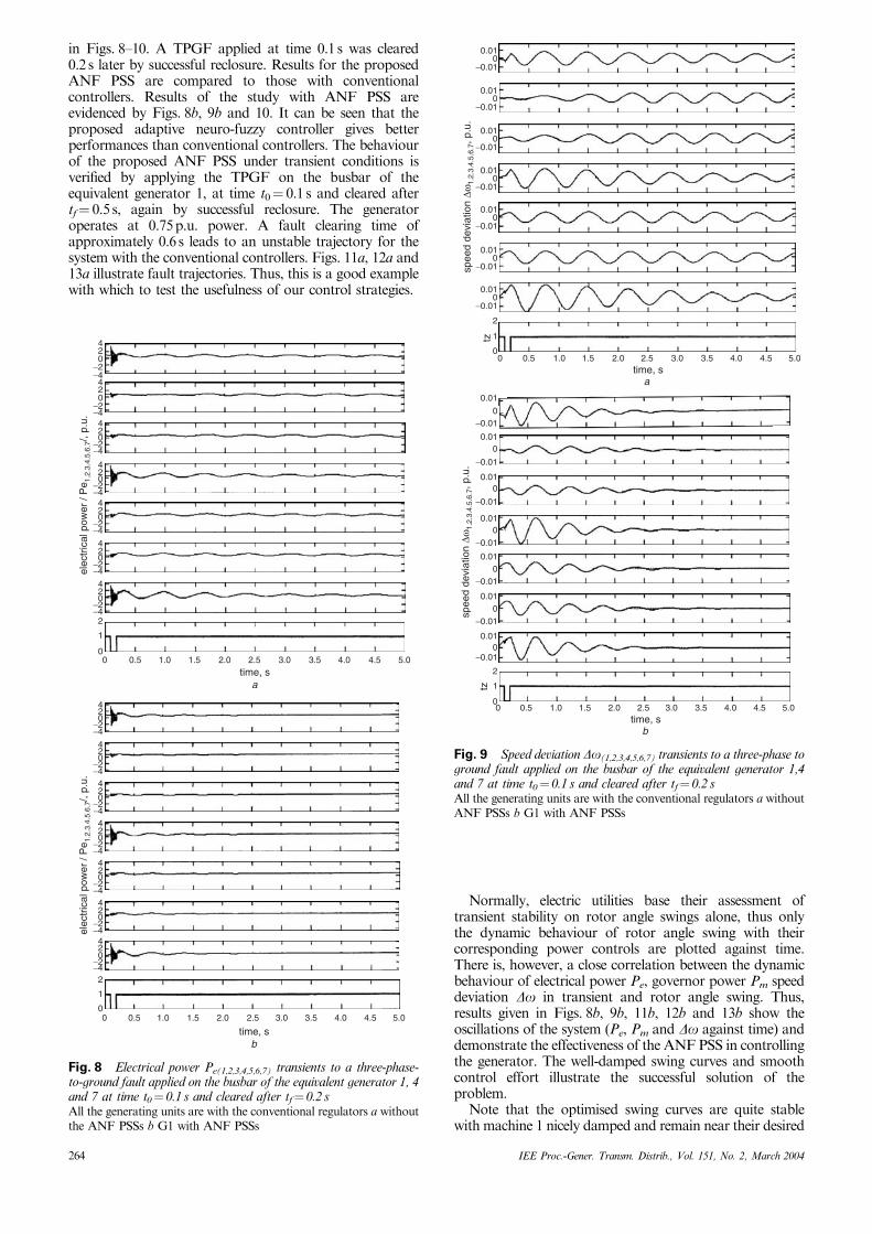
in Figs. 8–10. A TPGF applied at time 0.1 s was cleared0.2 s later by successful reclosure. Results for the proposedANF PSS are compared to those with conventionalcontrollers. Results of the study with ANF PSS areevidenced by Figs. 8b, 9b and 10. It can be seen that theproposed adaptive neuro-fuzzy controller gives betterperformances than conventional controllers. The behaviourof the proposed ANF PSS under transient conditions isverified by applying the TPGF on the busbar of theequivalent generator 1, at time t0¼ 0.1 s and cleared aftertf¼ 0.5 s, again by successful reclosure. The generatoroperates at 0.75 p.u. power. A fault clearing time ofapproximately 0.6 s leads to an unstable trajectory for thesystem with the conventional controllers. Figs. 11a, 12a and13a illustrate fault trajectories. Thus, this is a good examplewith which to test the usefulness of our control strategies.
Normally, electric utilities base their assessment oftransient stability on rotor angle swings alone, thus onlythe dynamic behaviour of rotor angle swing with theircorresponding power controls are plotted against time.There is, however, a close correlation between the dynamicbehaviour of electrical power Pe, governor power Pm speeddeviation Do in transient and rotor angle swing. Thus,results given in Figs. 8b, 9b, 11b, 12b and 13b show theoscillations of the system (Pe, Pm and Do against time) anddemonstrate the effectiveness of the ANF PSS in controllingthe generator. The well-damped swing curves and smoothcontrol effort illustrate the successful solution of theproblem.
Note that the optimised swing curves are quite stablewith machine 1 nicely damped and remain near their desired
42
0 1.0 1.5 2.0 2.5 3.0 3.5 4.0 4.5 5.00.5
0−2−4420
−2−4420
−2−4
420
−2−4420
−2−4
4
elec
tric
al p
ower
/ P
e 1.2
.3.4
.5.6
.7/,
p.u.
20
−2−4
420
0
−2−42
1
420
−2−4
420
−2−4420
−2−4420
−2−4420
−2−44
elec
tric
al p
ower
/ P
e 1.2
.3.4
.5.6
.7/,
p.u.
20
−2−4420
0
−2−42
1
time, sa
0 1.0 1.5 2.0 2.5 3.0 3.5 4.0 4.5 5.00.5
time, sb
Fig. 8 Electrical power Pe(1,2,3,4,5,6,7) transients to a three-phase-to-ground fault applied on the busbar of the equivalent generator 1, 4and 7 at time t0¼ 0.1 s and cleared after tf¼ 0.2 sAll the generating units are with the conventional regulators a withoutthe ANF PSSs b G1 with ANF PSSs
0.010
−0.01
0.010
−0.01
0.010
−0.01
0.010
−0.01
0.010
spee
d de
viat
ion
∆ω1.
2.3.
4.5.
6.7,
p.u
.
−0.01
0.010
−0.01
0.010
−0.01
2
tz 10
0.01
0−0.01
0.010
−0.01
0.010
−0.01
0.010
−0.01
0.010
spee
d de
viat
ion
∆ω1.
2.3.
4.5.
6.7,
p.u
.
−0.01
0.010
−0.01
0.010
−0.01
2
tz 1
0
0 1.0 2.0 3.0 4.0 5.00.5 1.5 2.5time, s
a
3.5 4.5
0 1.0 2.0 3.0 4.0 5.00.5 1.5 2.5time, s
b
3.5 4.5
Fig. 9 Speed deviation Do(1,2,3,4,5,6,7) transients to a three-phase toground fault applied on the busbar of the equivalent generator 1,4and 7 at time t0¼ 0.1 s and cleared after tf¼ 0.2 sAll the generating units are with the conventional regulators a withoutANF PSSs b G1 with ANF PSSs
264 IEE Proc.-Gener. Transm. Distrib., Vol. 151, No. 2, March 2004
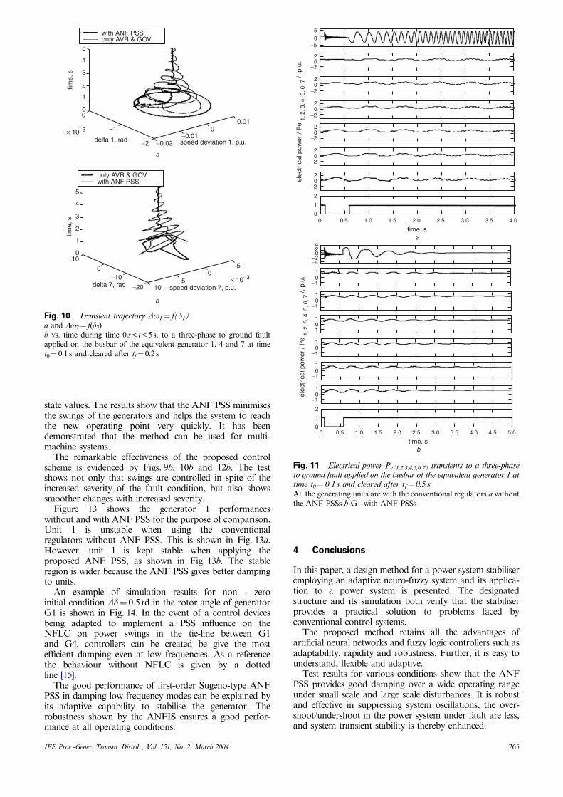
state values. The results show that the ANF PSS minimisesthe swings of the generators and helps the system to reachthe new operating point very quickly. It has beendemonstrated that the method can be used for multi-machine systems.
The remarkable effectiveness of the proposed controlscheme is evidenced by Figs. 9b, 10b and 12b. The testshows not only that swings are controlled in spite of theincreased severity of the fault condition, but also showssmoother changes with increased severity.
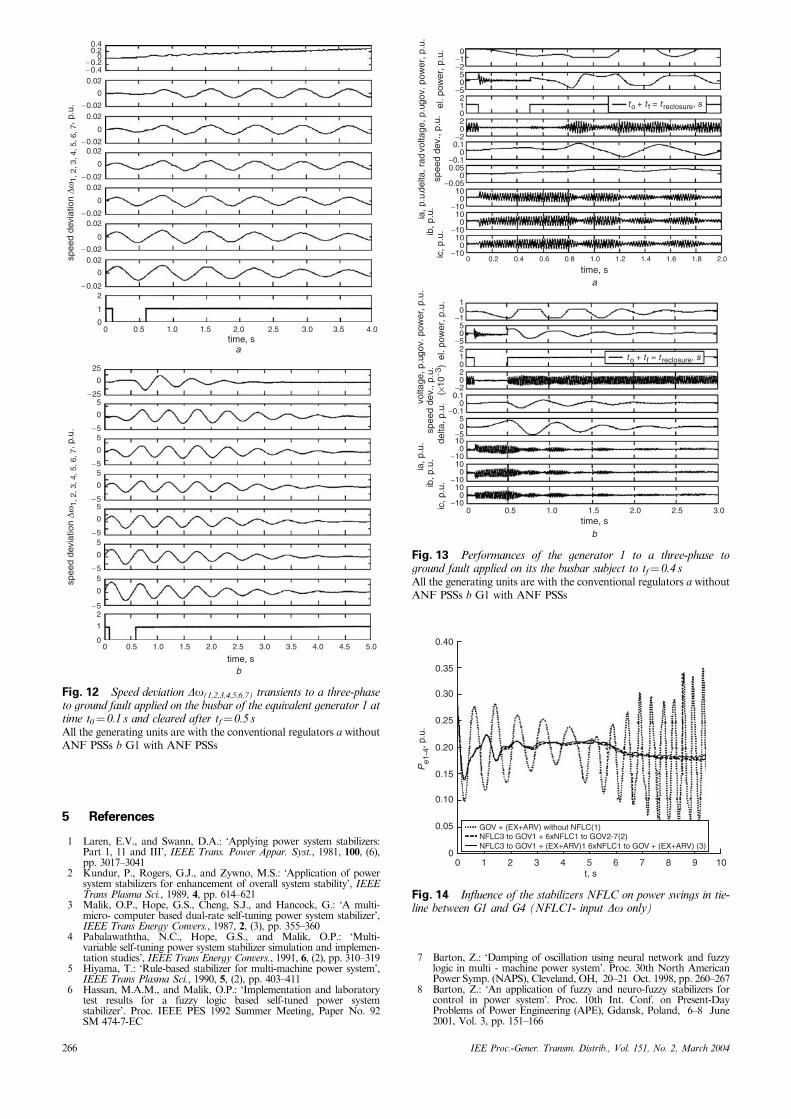
Figure 13 shows the generator 1 performanceswithout and with ANF PSS for the purpose of comparison.Unit 1 is unstable when using the conventionalregulators without ANF PSS. This is shown in Fig. 13a.However, unit 1 is kept stable when applying theproposed ANF PSS, as shown in Fig. 13b. The stableregion is wider because the ANF PSS gives better dampingto units.
An example of simulation results for non - zeroinitial condition Dd¼ 0.5 rd in the rotor angle of generatorG1 is shown in Fig. 14. In the event of a control devicesbeing adapted to implement a PSS influence on theNFLC on power swings in the tie-line between G1and G4, controllers can be created be give the mostefficient damping even at low frequencies. As a referencethe behaviour without NFLC is given by a dottedline [15].
The good performance of first-order Sugeno-type ANFPSS in damping low frequency modes can be explained byits adaptive capability to stabilise the generator. Therobustness shown by the ANFIS ensures a good perfor-mance at all operating conditions.
4 Conclusions
In this paper, a design method for a power system stabiliseremploying an adaptive neuro-fuzzy system and its applica-tion to a power system is presented. The designatedstructure and its simulation both verify that the stabiliserprovides a practical solution to problems faced byconventional control systems.
The proposed method retains all the advantages ofartificial neural networks and fuzzy logic controllers such asadaptability, rapidity and robustness. Further, it is easy tounderstand, flexible and adaptive.
Test results for various conditions show that the ANFPSS provides good damping over a wide operating rangeunder small scale and large scale disturbances. It is robustand effective in suppressing system oscillations, the over-shoot/undershoot in the power system under fault are less,and system transient stability is thereby enhanced.
elec
tric
al p
ower
/ P
e 1,
2, 3
, 4, 5
, 6, 7
/, p
.u.
elec
tric
al p
ower
/ P
e 1,
2, 3
, 4, 5
, 6, 7
/, p
.u.
btime, s
5.04.0 4.53.53.02.52.01.51.00.50
atime, s
4.03.53.02.52.01.51.00.5
50
−5
20
−2
20
−2
20
−2
20
−2
20
−2
420
−2−4
10
−1
10
−1
10
−1
10
−1
10
−1
10
−1
20
−2
2
1
0
2
1
00
Fig. 11 Electrical power Pe(1,2,3,4,5,6,7) transients to a three-phaseto ground fault applied on the busbar of the equivalent generator 1 attime t0¼ 0.1 s and cleared after tf¼ 0.5 sAll the generating units are with the conventional regulators a withoutthe ANF PSSs b G1 with ANF PSSs
5
4
3
2
1
−1
−2 −0.02−0.01
0.010
0
5
5
4
3
2
1
0
0
0
time,
stim
e, s
× 10−3
× 10−3
10
−10 −5−10−20
0
delta 1, rad
delta 7, rad
speed deviation 1, p.u.
speed deviation 7, p.u.
with ANF PSSonly AVR & GOV
with ANF PSSonly AVR & GOV
a
b
Fig. 10 Transient trajectory Do1¼ f(d1)a and Do7¼ f(d7)b vs. time during time 0 srtr5 s, to a three-phase to ground faultapplied on the busbar of the equivalent generator 1, 4 and 7 at timet0¼ 0.1 s and cleared after tf¼ 0.2 s
IEE Proc.-Gener. Transm. Distrib., Vol. 151, No. 2, March 2004 265
5 References
1 Laren, E.V., and Swann, D.A.: ‘Applying power system stabilizers:Part 1, 11 and III’, IEEE Trans. Power Appar. Syst., 1981, 100, (6),pp. 3017–3041
2 Kundur, P., Rogers, G.J., and Zywno, M.S.: ‘Application of powersystem stabilizers for enhancement of overall system stability’, IEEETrans Plasma Sci., 1989, 4, pp. 614–621
3 Malik, O.P., Hope, G.S., Cheng, S.J., and Hancock, G.: ‘A multi-micro- computer based dual-rate self-tuning power system stabilizer’,IEEE Trans Energy Convers., 1987, 2, (3), pp. 355–360
4 Pabalawaththa, N.C., Hope, G.S., and Malik, O.P.: ‘Multi-variable self-tuning power system stabilizer simulation and implemen-tation studies’, IEEE Trans Energy Convers., 1991, 6, (2), pp. 310–319
5 Hiyama, T.: ‘Rule-based stabilizer for multi-machine power system’,IEEE Trans Plasma Sci., 1990, 5, (2), pp. 403–411
6 Hassan, M.A.M., and Malik, O.P.: ‘Implementation and laboratorytest results for a fuzzy logic based self-tuned power systemstabilizer’. Proc. IEEE PES 1992 Summer Meeting, Paper No. 92SM 474-7-EC
7 Barton, Z.: ‘Damping of oscillation using neural network and fuzzylogic in multi - machine power system’. Proc. 30th North AmericanPower Symp. (NAPS), Cleveland, OH, 20–21 Oct. 1998, pp. 260–267
8 Barton, Z.: ‘An application of fuzzy and neuro-fuzzy stabilizers forcontrol in power system’. Proc. 10th Int. Conf. on Present-DayProblems of Power Engineering (APE), Gdansk, Poland, 6–8 June2001, Vol. 3, pp. 151–166
0.40.2
0.02
− 0.2
− 0.02
− 0.4
0
0
0.02
− 0.02
0
0.02
− 0.02
0
0.02
− 0.02
0
0.02
− 0.02
0
0.02
− 0.02
− 25
0
2
0
1
spee
d de
viat
ion
∆ω1,
2, 3
, 4, 5
, 6, 7
, p.u
. sp
eed
devi
atio
n ∆ω
1, 2
, 3, 4
, 5, 6
, 7, p
.u.
25
0
− 5
5
0
− 5
5
0
− 5
5
0
− 5
5
0
− 5
5
0
− 5
5
0
0
2
1
0 0.5 1.0 1.5 2.0 2.5 3.0 3.5 4.0time, s
a
0 0.5 1.0 1.5 2.0 2.5 3.0 3.5 4.0 4.5 5.0
time, sb
Fig. 12 Speed deviation Do(1,2,3,4,5,6,7) transients to a three-phaseto ground fault applied on the busbar of the equivalent generator 1 attime t0¼ 0.1 s and cleared after tf¼ 0.5 sAll the generating units are with the conventional regulators a withoutANF PSSs b G1 with ANF PSSs
0−1−250
−5
0.10
−0.1
20
−2
0.050
−0.05100
−10100
−10100
0 0.2
time, s
time, s
0.4 0.6 0.8 1.0 1.2 1.4 1.6 1.8 2.0−10
210
ib, p
.u.
ic, p
.u.
ia, p
.u.
gov.
pow
er, p
.u.
volta
ge, p
.u.
spee
d de
v., p
.u.
el. p
ower
, p.u
.
delta
, rad
10
−150
−5
0.10
−0.1
20
−2
50
−5100
−10100
−10100
−10
210
ib, p
.u.
ic, p
.u.
ia, p
.u.
gov.
pow
er, p
.u.
volta
ge, p
.u.
spee
d de
v., p
.u.
el. p
ower
, p.u
.de
lta, p
.u.
(×1
0−3)
0 0.5 1.0 1.5 2.0 2.5 3.0
a
b
t o + t f = t reclosure, s
t o + t f = t reclosure, s
Fig. 13 Performances of the generator 1 to a three-phase toground fault applied on its the busbar subject to tf¼ 0.4 sAll the generating units are with the conventional regulators a withoutANF PSSs b G1 with ANF PSSs
0.40
0.35
0.30
0.25
0.20
0.15
0.10
0.05
00 1 2 3 4 5 6 7 8 9 10
Pe1
-4, p
.u.
t, s
GOV + (EX+ARV) without NFLC(1)NFLC3 to GOV1 + 6xNFLC1 to GOV2-7(2)NFLC3 to GOV1 + (EX+ARV)1 6xNFLC1 to GOV + (EX+ARV) (3)
Fig. 14 Influence of the stabilizers NFLC on power swings in tie-line between G1 and G4 (NFLC1- input Do only)
266 IEE Proc.-Gener. Transm. Distrib., Vol. 151, No. 2, March 2004

9 MATLAB Application Interface Guide. MATLAB online documen-tation, The Math. Works Inc., Natic, MA, USA
10 Machowski, J., Bialek, J.W., and Bumby, J.R.: ‘Power SystemDynamics and Stability’ (J. Wiley & Sons, New York, 1998)
11 Jang, J.-S. R., and Sun, C.-T.: ‘Neuro-Fuzzy and Soft Computing: AComputational Approach to Learning and Machine Intelligence’(Prentice Hall, 1997)
12 ‘Neural Network & Fuzzy Logic Toolbox User’s Guide’ (The Math.Works Inc., Natic, MA, USA, 1995)
13 Ruhua, Y., Eghbali, H.J., and Nehrir, M.H.: ‘An online adaptiveneuro-fuzzy power system stabilizer for multimachine systems’, IEEETrans. Power Syst., 2003, 18, (1), pp. 128–135
14 Abido, M.A., and Abdel-Magid, Y.L.: ‘A hybrid neuro-fuzzy powersystem stabilizer for multimachine power systems Power Systems’,IEEE Trans. Power Syst., 1998, 13, (4), pp. 1323–1330
15 Barton, Z.: ‘Damping of oscillation in multimachine power system usestabilizers based on artificial intelligence’. Proc. S.T.U., z 185, Gliwice,2003, pp. 1–192
IEE Proc.-Gener. Transm. Distrib., Vol. 151, No. 2, March 2004 267