robust, compact implementation of an off-axis digital ... · robust, compact implementation of an...
TRANSCRIPT

Robust, compact implementation of an off-axis digital holographic microscope
J. Kent Wallace,1,* Stephanie Rider,2 Eugene Serabyn,1 Jonas Kühn,1 Kurt Liewer,1 Jody Deming,3 Gordon Showalter,3 Chris Lindensmith,1 and Jay Nadeau2,4,5
1Jet Propulsion Laboratory, California Institute of Technology, 4800 Oak Grove Dr., Pasadena, CA. 91109, USA 2Division of Aerospace Engineering, California Institute of Technology, 1200 E. California Blvd., Pasadena CA
91125, USA 3Department of Biological Oceanography, University of Washington, 1503 NE Boat Street, Seattle WA 98105, USA
4Department of Biomedical Engineering, McGill University, 3775 University St., Montreal, Quebec, H3A 2B4, Canada
5Current address: Division of Aerospace Engineering, California Institute of Technology, 1200 E. California Blvd., Pasadena CA 91125, USA
Abstract: Recent advances in digital technologies, such as high-speed computers and large-format digital imagers, have led to a burgeoning interest in the science and engineering of digital holographic microscopy (DHM). Here we report on a novel off-axis DHM, based on a twin-beam optical design, which avoids the limitations of prior systems, and provides many advantages, including compactness, intrinsic stability, robustness against misalignment, ease of use, and cost. These advantages are traded for a physically constrained sample volume, as well as a fixed fringe spacing. The first trade is not overly restrictive for most applications, and the latter provides for a pre-set assembly alignment that optimizes the spatial frequency sampling. Moreover, our new design supports use in both routine laboratory settings as well as extreme environments without any sacrifice in performance, enabling ready observation of microbial species in the field. The instrument design is presented in detail here, along with a demonstration of bacterial video imaging at sub-micrometer resolution at temperatures down to –15 °C.
©2015 Optical Society of America
OCIS codes: (090.1995) Digital holography; (120.2880) Holographic interferometry.
References and links
1. C. Knox, “Holographic microscopy as a technique for recording dynamic microscopic subjects,” Science 153(3739), 989–990 (1966).
2. A. Chengala, M. Hondzo, and J. Sheng, “Microalga propels along vorticity direction in a shear flow,” Phys. Rev. E Stat. Nonlin. Soft Matter Phys. 87(5), 052704 (2013).
3. J. Sheng, E. Malkiel, J. Katz, J. Adolf, R. Belas, and A. R. Place, “Digital holographic microscopy reveals prey-induced changes in swimming behavior of predatory dinoflagellates,” Proc. Natl. Acad. Sci. USA 104(44), 17512–17517 (2007).
4. J. Sheng, E. Malkiel, J. Katz, J. E. Adolf, and A. R. Place, “A dinoflagellate exploits toxins to immobilize prey prior to ingestion,” Proc. Natl. Acad. Sci. U.S.A. 107(5), 2082–2087 (2010).
5. S. M. Vater, J. Finlay, M. E. Callow, J. A. Callow, T. Ederth, B. Liedberg, M. Grunze, and A. Rosenhahn, “Holographic microscopy provides new insights into the settlement of zoospores of the green alga Ulva linza on cationic oligopeptide surfaces,” Biofouling 31(2), 229–239 (2015).
6. N. Pavillon, J. Kühn, C. Moratal, P. Jourdain, C. Depeursinge, P. J. Magistretti, and P. Marquet, “Early cell death detection with digital holographic microscopy,” PLoS ONE 7(1), e30912 (2012).
7. P. Marquet, B. Rappaz, P. J. Magistretti, E. Cuche, Y. Emery, T. Colomb, and C. Depeursinge, “Digital holographic microscopy: a noninvasive contrast imaging technique allowing quantitative visualization of living cells with subwavelength axial accuracy,” Opt. Lett. 30(5), 468–470 (2005).
8. B. Kemper, D. Carl, J. Schnekenburger, I. Bredebusch, M. Schäfer, W. Domschke, and G. von Bally, “Investigation of living pancreas tumor cells by digital holographic microscopy,” J. Biomed. Opt. 11(3), 034005 (2006).
#240254 Received 5 May 2015; revised 5 Jun 2015; accepted 21 Jun 2015; published 24 Jun 2015 © 2015 OSA 29 Jun 2015 | Vol. 23, No. 13 | DOI:10.1364/OE.23.017367 | OPTICS EXPRESS 17367

9. P. Jourdain, N. Pavillon, C. Moratal, D. Boss, B. Rappaz, C. Depeursinge, P. Marquet, and P. J. Magistretti, “Determination of transmembrane water fluxes in neurons elicited by glutamate ionotropic receptors and by the cotransporters KCC2 and NKCC1: a digital holographic microscopy study,” J. Neurosci. 31(33), 11846–11854 (2011).
10. H. Janeckova, P. Vesely, and R. Chmelik, “Proving tumour cells by acute nutritional/energy deprivation as a survival threat: a task for microscopy,” Anticancer Res. 29(6), 2339–2345 (2009).
11. M. Falck Miniotis, A. Mukwaya, and A. Gjörloff Wingren, “Digital holographic microscopy for non-invasive monitoring of cell cycle arrest in L929 cells,” PLoS ONE 9(9), e106546 (2014).
12. T.-W. Su, L. Xue, and A. Ozcan, “High-throughput lensfree 3D tracking of human sperms reveals rare statistics of helical trajectories,” Proc. Natl. Acad. Sci. U.S.A. 109(40), 16018–16022 (2012).
13. T. Fenchel, “Microbial behavior in a heterogeneous world,” Science 296(5570), 1068–1071 (2002). 14. T. Fenchel, “Eppur si muove: many water column bacteria are motile,” Aquat. Microb. Ecol. 24(2), 197–201
(2001). 15. J. G. Mitchell and K. Kogure, “Bacterial motility: links to the environment and a driving force for microbial
physics,” FEMS Microbiol. Ecol. 55(1), 3–16 (2006). 16. E. M. Purcell, “Life at low Reynolds number,” Am. J. Phys. 45(1), 3–11 (1977). 17. M. J. Rivera and D. Y. Sumner, “Unraveling the three-dimensional morphology of archean microbialites,” J.
Paleontol. 88(4), 719–726 (2014). 18. U. Schnars and W. Jüptner, “Direct Recording of Holograms by a CCD Target and Numerical Reconstruction,”
Appl. Opt. 33(2), 179–181 (1994). 19. U. Schnars and W. Juptner, “Digital recording and numerical reconstruction of holograms,” Meas. Sci. Technol.
13(9), R85–R101 (2002). 20. E. Cuche, P. Marquet, and C. Depeursinge, “Simultaneous amplitude-contrast and quantitative phase-contrast
microscopy by numerical reconstruction of Fresnel off-axis holograms,” Appl. Opt. 38(34), 6994–7001 (1999). 21. E. Cuche, P. Marquet, and C. Depeursinge, “Spatial filtering for zero-order and twin-image elimination in digital
off-axis holography,” Appl. Opt. 39(23), 4070–4075 (2000). 22. C. Mann, L. Yu, C. M. Lo, and M. Kim, “High-resolution quantitative phase-contrast microscopy by digital
holography,” Opt. Express 13(22), 8693–8698 (2005). 23. F. Zhang, G. Pedrini, and W. Osten, “Reconstruction algorithm for high-numerical-aperture holograms with
diffraction-limited resolution,” Opt. Lett. 31(11), 1633–1635 (2006). 24. T. Colomb, E. Cuche, F. Charrière, J. Kühn, N. Aspert, F. Montfort, P. Marquet, and C. Depeursinge,
“Automatic procedure for aberration compensation in digital holographic microscopy and applications to specimen shape compensation,” Appl. Opt. 45(5), 851–863 (2006).
25. W. Xu, M. H. Jericho, I. A. Meinertzhagen, and H. J. Kreuzer, “Digital in-line holography for biological applications,” Proc. Natl. Acad. Sci. U.S.A. 98(20), 11301–11305 (2001).
26. M. Molaei and J. Sheng, “Imaging bacterial 3D motion using digital in-line holographic microscopy and correlation-based de-noising algorithm,” Opt. Express 22(26), 32119–32137 (2014).
27. I. Yamaguchi and T. Zhang, “Phase-shifting digital holography,” Opt. Lett. 22(16), 1268–1270 (1997). 28. S. K. Jericho, P. Klages, J. Nadeau, E. M. Dumas, M. H. Jerico, and J. J. Kreuzer, “In-line digital holographic
microscopy for terrestrial and exobiological research,” Planet. Space Sci. 58(4), 701–705 (2010). 29. J. Kühn, B. Niraula, K. Liewer, J. Kent Wallace, E. Serabyn, E. Graff, C. Lindensmith, and J. L. Nadeau, “A
Mach-Zender digital holographic microscope with sub-micrometer resolution for imaging and tracking of marine micro-organisms,” Rev. Sci. Instrum. 85(12), 123113 (2014).
30. K. Junge, H. Eicken, and J. W. Deming, “Motility of colwellia psychrerythraea strain 34H at subzero temperatures,” Appl. Environ. Microbiol. 69(7), 4282–4284 (2003).
31. Y. Gong and I. F. Sbalzarini, “Image enhancement by gradient distribution specification,” Proc. ACCV, 12th Asian Conference on Computer Vision Workshop on Emerging Topics in Image Enhancement and Restoration, w7–p3 (2015).
1. Introduction
Bacterial motility plays a role in critical environmental and physiological processes, including nutrient cycling, biofouling, and virulence. Despite its importance, motility has only been studied in a few test organisms because of the difficulties of imaging moving micrometer-sized cells. However, the study of the motility of microorganisms is a field which promises to be revolutionized by digital holographic microscopy (DHM) [1]. Because this imaging technique instantaneously probes a large sample volume (milliliters) in three dimensions, it enables the reconstruction of swimming trajectories of essentially unconstrained cells. The feasibility of this approach has been demonstrated in the open ocean for measurements of the distribution and swimming patterns of plankton [2], and investigation of dinoflagellate feeding behavior [3,4]. It has also been used in the laboratory to study motility of algal zoospores [5] and cultured cells [6–12]. However, because of the technical limitations of
#240254 Received 5 May 2015; revised 5 Jun 2015; accepted 21 Jun 2015; published 24 Jun 2015 © 2015 OSA 29 Jun 2015 | Vol. 23, No. 13 | DOI:10.1364/OE.23.017367 | OPTICS EXPRESS 17368

existing fieldable DHM instruments, such field experiments have so far been restricted to eukaryotic cells >10 µm in diameter. In order to capture bacterial motility, real-time imaging with spatial resolution of < 1 µm in all dimensions is required. Such an instrument would allow for in situ investigations of bacterial motility in bodies of water, which has relevance to basic physics and microbiology [13–16] as well as to applications such as water-quality monitoring and astrobiology [17]
Imaging moving bacteria is challenging because of the small size of the cells, their rapid motion (tens to hundreds of cell lengths per second), and their low contrast. Light microscopy relies upon a wide selection of dyes for increasing contrast of specific cell types and subcellular structures. An “off-axis” DHM provides both amplitude and phase images, where contrast in the amplitude image is provided by sample absorptivity at the probe wavelength, and contrast in the phase image results from a difference in index of refraction between the sample and its surrounding medium. Depending upon the organism, one or the other of these image types (or their derived constructs such as phase contrast or DIC) may provide sufficient contrast for identifying and tracking single cells, making dyes unnecessary. This is a distinct advantage over single-beam or “in-line” instruments, where the amplitude and phase images cannot be readily deconvolved without modifications that preclude real-time observation.
This paper reports an off-axis DHM instrument. It implements the off-axis geometry as a compact, twin-beam layout which renders the instrument largely insensitive to errors in alignment, making it ideal for rough transport and handling conditions. It demonstrates sub-micron lateral resolution inside a 3D volume of 360 x 360 x > 600 μm3 permitting imaging and tracking of multiple single bacterial cells. Furthermore, the proposed system is implemented in a self-aligned robust lightweight package requiring no fine alignment, which make it ideal for field use. We will first describe the instrument, then summarize its capabilities and advantages, then highlight the performance of the instrument using an extremophile bacterial test species, including measurements made at sub-freezing temperatures.
2. Digital holographic microscopy: methods and instruments
In digital holography, recording of the optical interference – fringes – is not done with photographic plates, but with an array detector [18–20]. To record fringes of high contrast over the detector integration time requires: 1) the optical path length difference between the reference arm and science arm be well within the coherence length of the source, 2) that the fringes not shift significantly during the exposure time (which is equivalent to saying the path length variations must be stable to much less than a wavelength at this timescale). For off-axis holography the fringe carrier frequency must also be well sampled by the CCD, in order to accommodate the sample bandwidth [21].
Like classic holography, digital holography enables the reconstruction of an electric field at a given plane a-posteriori – but it relies upon a computer to perform a numerical reconstruction [22–24]. However, it adds two unique capabilities: the ability to numerically reconstruct this electric field at any other plane along the optical axis, and do so as a function of time. In this way, data acquisition consists of a time series of recorded holograms, and afterwards the electric field in a volume is numerically reconstructed for each time stamp, creating a time-lapse movie of a three-dimensional volume.
Several optical configurations have been proposed for the recording step in digital holography: 1) lens-less “Gabor-type” configuration with a simple pinhole divergent illumination [25] or 2) inline holography schemes usually enable compact and straightforward implementation. Although a dual-beam in-line geometry is compatible with phase-shifting [26] (at the price of real-time capability), the previously-mentioned schemes generally cannot discard or deconvolve the contribution from the “twin image” (complex conjugate) of the reconstructed field, hence superposing the final image with an out-of-focus “ghost”. Alternatively, off-axis implementations, using a tilted reference wave to encode the sample
#240254 Received 5 May 2015; revised 5 Jun 2015; accepted 21 Jun 2015; published 24 Jun 2015 © 2015 OSA 29 Jun 2015 | Vol. 23, No. 13 | DOI:10.1364/OE.23.017367 | OPTICS EXPRESS 17369

wavefront with a fringe pattern, have been employed [18,20]: these provide a spatial multiplexing in the Fourier domain, thus enabling spatial filtering [21] and retrieval of the object complex wavefront free of artifacts. However, off-axis layouts frequently result in rather large instruments, which are alignment-sensitive (notably for accurately dialing the fringe carrier frequency). They are generally less-suited for extreme environments in terms of mechanical and thermal stress with their two-beam geometry (usually Mach-Zehnder or Michelson-type). Our new design presented below maintains the off-axis implementation, but with a robust optical design which maintains performance.
3. Design description of the compact, twin-beam off-axis digital holographic microscope system
A diagram of the optical system is shown in Fig. 1(a). This diagram captures the key components but is not to scale, so lengths and angles are not representative of the as-built system, as shown in the CAD drawing in Fig. 1(b). A photograph of the actual instrument is given in Fig. 1(c), and specifications in Table 1. There are four main components to the system: the source, the sample, the microscope optics, and the sensor.
Fig. 1. Schematic and images of the compact, twin-beam digital holographic microscope in its laboratory implementation. (a) Schematic showing four main elements (discussed in the text): the source, the sample (specimen path is labeled Spec. and reference path is labeled Ref.), the microscope, and the sensor. (b) Solid model of the hardware. The fiber-fed source assembly is at the bottom, and the imaging camera is at the top. The microscope optics – comprised of the two aspheric lenses and the relay lens – are contained within the 300 mm long lens tube. The three- axis stage between the source the microscope optics provides easy manual manipulation of the specimen under study. (c) Photograph of the instrument in the laboratory. A shutter over the collimating lens protects against condensation, and is operated remotely by a controller (see Section 5 for a discussion)
#240254 Received 5 May 2015; revised 5 Jun 2015; accepted 21 Jun 2015; published 24 Jun 2015 © 2015 OSA 29 Jun 2015 | Vol. 23, No. 13 | DOI:10.1364/OE.23.017367 | OPTICS EXPRESS 17370

Table 1. Fundamental Properties of the compact, twin-beam DHM system
Property Value Unit Note Operating Wavelength 405 nm Single-mode fiber-coupled laser Objective focal length - fo 7.6 mm Aspheric singlet Objective Numerical Aperture 0.30 Relay lens focal length - fr 150 mm Achromatic Doublet System magnification 19.7 Lateral resolution 0.7 μm CCD pixel size 3.45 x 3.45 μm x μm 2448 x 2050 CCD chip Sample imaging volume 360 x 360 x > 600a μm x μm x μm In 2048 x 2048 (4Mpx) mode Sampling Rate 15 frames per sec 4Mpx mode; 22 fps with 1Mpx Instrument length 400 mm Input fiber to back of CCD aA measurement of the instrument lateral resolution for different depths demonstrated it is capable of < 1 μm lateral resolution over a sample depth of 900 μm. Our sample chamber is 600 μm deep.
3.1 Source
The source is a single mode fiber-coupled laser diode, operating at a wavelength of 405 nm to optimize lateral resolution while avoiding phototoxic ultraviolet, and a one-inch diameter f = 100 mm collimating lens. Optical power is tunable between 1 and 10 mW depending on the choice of camera shutter time. The beam illuminates two sample volumes that are spatially located ± 3 mm away from the optical axis. The use of the single mode input as a source ensures a high degree of spatial coherence. We chose a lens matched to the numerical aperture of the optical fiber, such that the sub-apertures are homogeneously illuminated and the aberration from the collimator is kept small over each sub-pupil.
3.2 Microscope optics
The microscope assembly is composed of a pair of aspheric singlets as objectives, followed by a common relay lens. Aspheric lenses are chosen because they are of sufficient quality to yield diffraction-limited imaging capabilities while avoiding the cost and complexity of compound objectives. In an interferometric system, it is important to minimize internal reflections. These are unavoidable in compound objectives, which usually contain a handful of lenses to correct for several colors of spherical and chromatic aberration. Because we are using monochromatic light, we do not require correction for chromatic aberration or spherical correction for more than one wavelength. The aspheric lenses have moderately high numerical aperture (NA ~0.3), a clear aperture of 4.7 mm, and are separated from each other by 6 mm. The focal length of these objectives, represented by fo, is 7.6 mm. At the front focal plane is the sample being imaged, and at the back focal plane is a circular pupil stop which is sized such that the image performance remains diffraction limited, while preventing scattering contributions in the downstream tube from marginal rays. In the reference arm, the illumination simply passes through a channel that is either clear glass, or glass plus sample-free liquid.
The relay lens of the microscope has two functions. First, because both reference and object beams are located off the axis of symmetry of the relay lens, upon passing through this lens, the beams will be directed towards each other and meet a focal length away where the detector is located. The separation of the beams, s, and the focal length of the lens fr give the angle θfr at which the beams are recombined:
fr
s
frθ = (1)
#240254 Received 5 May 2015; revised 5 Jun 2015; accepted 21 Jun 2015; published 24 Jun 2015 © 2015 OSA 29 Jun 2015 | Vol. 23, No. 13 | DOI:10.1364/OE.23.017367 | OPTICS EXPRESS 17371

The second action of the lens is to form a real image of the sample onto the imaging array. This image will be magnified by the ratio of the focal lengths, m = fr/fo. In the actual instrument, the relay lens has a focal length of ~150 mm, and the magnification is therefore x19.7. The actual image planes within the sample volume are then reconstructed numerically, with the nominal working distance (WD) of the objectives of 1.2 mm corresponding to a median reconstruction distance of zero (in-focus on the CCD array).
3.3 Imaging sensor
The final component in the system is the imaging sensor (we use two cameras interchangeably, the Baumer TXG-50 and the AVT Prosilica GT2450B), for which the goals are a large field of view with small pixels and rapid readout. The two cameras use an identical sensor array, however the Prosilica is rated for lower operating temperature, hence more suited for field operation. The main requirement for the camera is that the fringes be oversampled to simultaneously accommodate the bandwidth of the magnified sample, while separating the interference terms in the Fourier domain with no overlap to enable spatial filtering [9]. These adjacent pixels are to be along the detector diagonal to optimize the sampling. A first approximation of this angle at which the beams recombine at the focal plane corresponds to the mid-point along the diagonal bandwidth of the detector, which is given by:
2 2frs p> (2)
where sfr is the fringe spacing and p is the pixel edge size, or
2 2
frp
λθ < (3)
A wavelength of 405 nm and a pixel size of 3.45 x 3.45 µm2 results in a recombination angle at the detector of 0.0415 radians (2.378 degrees). From Eq. (1), the instrumental fringe spacing provided by the baseline between the two objective lenses is 6 mm/150 mm, or 0.04 rad (2.29 degrees), which thus meets this requirement.
In this compact, twin-beam design, the ratio of the spatial resolution to the fringe spacing is given by s/do, where do is the objective diameter and s is the lateral separation between the objective lens pair. This ratio is in general ≥ 1, being unity in the limiting case of two identical side-by-side lenses in contact. Thus choosing a pixel size to properly sample the fringes will inherently lead to an adequate sampling of the point spread function (PSF). The lateral resolution at the object plane is given by λ/2NA, which for our system is 0.405 µm/0.6 = 0.7 µm. This PSF is magnified by a factor of about 20 in this system, so at the detector the spot size is 14 µm, which is indeed well oversampled by 3.5-micron pixels.
3.4 Opto-mechanics
The optics are mounted in commercially available lens tube assemblies. Use of these components yields a readily affordable system that is mechanically stiff, thus ensuring long-term stability. The lens tubes entirely enclose the optics, thus mitigating against both particulate contamination and turbulence due to stray air currents. The lens tubes are internally threaded and black anodized which acts to baffle stray light. The element which holds the aspheric lenses is a 3D printed part. It precisely sets the lens separation, and references them to the pupil stop at their back focal length.
In this laboratory implementation, the lens tube mechanics are mounted vertically on a rail. This has the advantage of being compatible with liquid sample chambers, with little to no effect of gravity on the specimens. A three-axis manual stage is added to this rail to permit manipulation of the sample chamber located between the source collimator and the objective pairs. An electrically controlled shutter between the collimation lens assembly and twin
#240254 Received 5 May 2015; revised 5 Jun 2015; accepted 21 Jun 2015; published 24 Jun 2015 © 2015 OSA 29 Jun 2015 | Vol. 23, No. 13 | DOI:10.1364/OE.23.017367 | OPTICS EXPRESS 17372

objectives shields the source lens, which is “up-looking,” from contamination and condensation when exposed to sudden temperature gradients.
3.5 Sample chamber
The fundamental requirement of this design is that the two arms – science and reference – be matched in optical path to the detector to within the coherence length of the laser. For samples of low density, and where absolute motility is not required (such as those often collected in environmental microbiology) there is no optical need to distinguish between science and reference beams, and there is no need to partition. The samples fluid may serve as both reference and object. However, we note that this choice is acceptable for motility studies where the absolute position is not required. In studies of taxis where it is fundamental to know if a specimen is swimming towards or away from a given stimulus, it’s necessary to distinguish science and reference sample chambers. Thus, an ordinary microscope slide and coverslip make an appropriate sample for this instrument, and the bacterial data presented in this paper were taken using this arrangement. An adhesive silicone gasket may be used to create a deeper chamber by cutting a rectangular or square well > 6 mm on a side and sandwiching it between the slide and coverslip.
For dense samples, it is desirable to have a reference chamber filled with a blank solution, with the sample contained only within the object chamber. Commercial chamber slides are available with the correct spacing; for example, Electron Microscopy Sciences part 70326-30.
In all cases, it is important that the beams pass through optical-quality glass or a very thin polymer layer. Quantitative phase information cannot be extracted for samples imaged through polymers such as polydimethylsiloxane (PDMS) because of the complex phase structure of these materials.
4. Comparison of the compact, twin-beam microscope with other DHM designs
The compact, twin-beam system as presented here has several advantages. The instrument is intrinsically coherent, in that the optical path lengths from the center of the science window, and the center of the reference window to the center of the CCD are identical, as are the paths from the laser to the center of the sample and reference windows. Thus, the zero optical path difference position is always at the center of the CCD. This intrinsic instrumental coherence reduces the requirement for coherence and stability of the source, reducing cost and making the instrument easier to set up.
The system is also insensitive to misalignment, at least to first order regarding slight deviations from nominal position due to shocks, thermal bending or assembly repeatability. Axial motion of the camera is not important, because the electric field measured at the CCD can be used to reconstruct the field at different depths [20,22,23]. The position of the relay lens is also not critical, as it determines the final image plane relative to the CCD, which, as mentioned, is not critical. Given that the science objective images the sample to infinity, to first order a change in the objective lens/relay lens separation will not change the final image location on the sensing array. The aspheric lenses are co-mounted in a single holder, so both elements move together as a unit. Any lateral motion relative to the sample or relay lens only laterally shifts the final image position on the CCD, which is unimportant for large detector arrays. Finally, small relative motion of the source assembly with respect to the rest of the microscope is also unimportant in all three degrees of freedom, because the source beam is collimated. This compact, twin-beam system is thus insensitive to essentially all potential slight misalignments of its optics. Finally, because of the ability of the system to reconstruct images to a range of distances, the source axial location need not be set extremely precisely either, allowing for relatively inexpensive sample stages.
Overall, our system has fewer elements and is more compact than traditional off-axis DHM layouts, such as the Mach-Zehnder implementation [20,27], albeit probably not compatible with extremely high NA immersion objectives. Indeed, the roles of the split
#240254 Received 5 May 2015; revised 5 Jun 2015; accepted 21 Jun 2015; published 24 Jun 2015 © 2015 OSA 29 Jun 2015 | Vol. 23, No. 13 | DOI:10.1364/OE.23.017367 | OPTICS EXPRESS 17373

beamsplitter and the recombination beamsplitter in the Mach-Zehnder are played by the single mode input fiber and CCD focal plane array, respectively. In addition, the “natural” fringe spacing provided by the common relay lens greatly facilitate the initial alignment in the lab, and is a non-issue in the field should the instrument be serviced in rough environmental conditions. To some extent, our proposed twin-beam geometry shares the compactness advantage offered by inline pinhole DHM systems, as previously used for microbial life studies in wet environments [25,28]. However, in addition, it also benefits from increased inherent robustness, and relies on an off-axis geometry to deliver true quantitative wavefront retrieval which is free of artifacts. The only real trade of this geometry is that the overall dimensions of any sample should not exceed a few millimeters, at least in one direction, in the case where one needs to accommodate a free beam path for the reference arm. This is not an issue with a large range of biological applications.
5. Measured performance of the compact, twin-beam system in the lab
The performance of the microscope was validated by quantifying its resolving power with a high-resolution US Air Force Target. This measurement was non-trivial, as the highest resolution targets are at the center of the target, yet a clear, reference window 6 mm from the target is required for the reference beam. However, it was indeed possible to image this area with the system, and the imaging performed as expected. Figure 2 shows an amplitude (a1) and phase (a2) reconstruction of a hologram of the resolution target as recorded by the compact, twin-beam system. Group 9 was clearly resolved; within this group, element 3 has a spatial frequency of 645 line pairs/mm (0.78 μm wide lines). We used KOALA software from LynceeTec for the holographic reconstructions [29].
Lateral resolution in aqueous solution was examined by imaging a bacterial test species, the marine psychrophile Colwellia psychrerythraea strain 34H. Figures 2(b) and 2(c) show amplitude and phase reconstructions of organisms at a density of ~107 cells/mL on a microscope slide. The phase and intensity images are reconstructions on a single z-plane; they were cropped and median-subtracted to reduce noise, but otherwise unprocessed. The different noise patterns and contrast of the intensity and phase images can be readily appreciated from these images; the system is clearly able to resolve individual cells.
We note that this instrument is also appropriate for imaging many types of biological samples, as long as the samples are consistent with the lateral image size (360 μm x 360 μm) and the lens separation of 6 mm. Cultured mammalian cells and organisms as large as Caenorhabditis elegans may be readily visualized.
#240254 Received 5 May 2015; revised 5 Jun 2015; accepted 21 Jun 2015; published 24 Jun 2015 © 2015 OSA 29 Jun 2015 | Vol. 23, No. 13 | DOI:10.1364/OE.23.017367 | OPTICS EXPRESS 17374

Fig. 2. Resolution performance of the compact, twin-beam system. A standard USAF resolution target reconstruction in amplitude (a1) and phase (a2). This image shows group 9, and all three elements resolved. Group 9, element 3 has a line width of 0.78 μm. (b) Phase reconstruction of an image of live, motile bacterial cells. A phase shift from dark to light occurs as the organisms swim out of the focal plane (arrow). (c) Intensity reconstruction of the same bacterial cell image.
The fringe stability for the new design is favorable, with optical path length jitter of only a small fraction of a wavelength over several seconds. The fringes are then essentially frozen by the typical exposure time of a few tens of milliseconds or less. This stability allows for adjustment of laser power and integration time depending solely upon the motility of the species under study, and not the instrument stability.
We also note that early versions of the compact, twin-beam system suffered from residual ring-like features which also caused spurious amplitude effects. We suspect that these effects were due to tooling marks from the aspheric lens molds. Judicious selection of superior quality aspheric lenses removed these unwanted features.
6. Operation of the compact, twin-beam system in below-zero environments
A key goal of this new DHM configuration is to allow microbiologists to take the instrument into the field for in situ studies of bacteria, including extremophiles. This will require operation at extreme ambient temperatures and humidity conditions, as bacterial motility has been observed down to –10 °C. In order to test our instrument under these harsh conditions, we performed preliminary experiments using a laboratory freezer to provide the extreme temperatures we anticipated experiencing during operation. These hardware tests also allowed
#240254 Received 5 May 2015; revised 5 Jun 2015; accepted 21 Jun 2015; published 24 Jun 2015 © 2015 OSA 29 Jun 2015 | Vol. 23, No. 13 | DOI:10.1364/OE.23.017367 | OPTICS EXPRESS 17375

us to image bacterial motility of species at different temperatures and salinities, and to confirm previous results on the extreme temperature limit of bacterial motility.
The entire rail-mounted instrument as shown in Fig. 1(c) was placed into a freezer and monitored for any significant degradation in performance during operation over the course of ten days. The freezer set-point was changed from −11 to −26 °C to explore the science and engineering at these temperatures. A single layer of insulation (bubble wrap) was placed around the camera, with a thermocouple to monitor camera temperature. The camera was left on and actively capturing images throughout the duration of the experiments, and its temperature did not fall below 20 °C. The instrument operation and performance were unchanged over these temperatures, with only one minor issue: when the freezer door was opened, outside humidity quickly condensed on the collimation lens, causing it to fog over with ice crystals. Once the door was closed, this would dissipate over the span of a few minutes and the instrument would return to routine operation, but after several episodes of icing and de-icing it was necessary to remove and clean the collimating lens. In order to prevent fog formation, an electrically controlled shutter was added just above the collimation lens. When the shutter was closed each time the freezer door was opened, collimator icing was prevented.
We used this setup to investigate two- and three-dimensional swimming behavior of C. psychrerythraea. This organism has been previously reported to show motility down to at least –10 °C, in experiments conducted with a light microscope inside a temperature-controlled cold room [30]. Motility stopped at –15 °C, with only Brownian motion apparent. In our experiments, because the achievable freezer settings of −11 to −26 °C were at the lower limits of the range of interest, we used a resistive heat stage to ramp the sample chambers across a range desired target temperatures from 0 °C down to the point where freezing occurred. A thermocouple on the stage and a resistance temperature detector (RTD) inside the sample chamber measured the stage and sample temperature, respectively.
Figures 3(a)-3(c) show hologram, phase, and intensity images of a C. psychrerythraea culture in growth medium and 10% glycerol at –16 °C. The images were of sufficient quality to permit thresholding and object tracking using MOSAIC [31]. Figures 3(d)-3(f) show 2-dimensional tracks of bacteria at + 6, –13, and –15 °C. It can be readily seen that the cells were highly active at + 6 °C, with characteristic darting and reversing motions. At −13 °C, most cells did not show motility, though a few retained very fast swimming. By −15 °C, only Brownian motion and slight sample drift could be observed.
#240254 Received 5 May 2015; revised 5 Jun 2015; accepted 21 Jun 2015; published 24 Jun 2015 © 2015 OSA 29 Jun 2015 | Vol. 23, No. 13 | DOI:10.1364/OE.23.017367 | OPTICS EXPRESS 17376
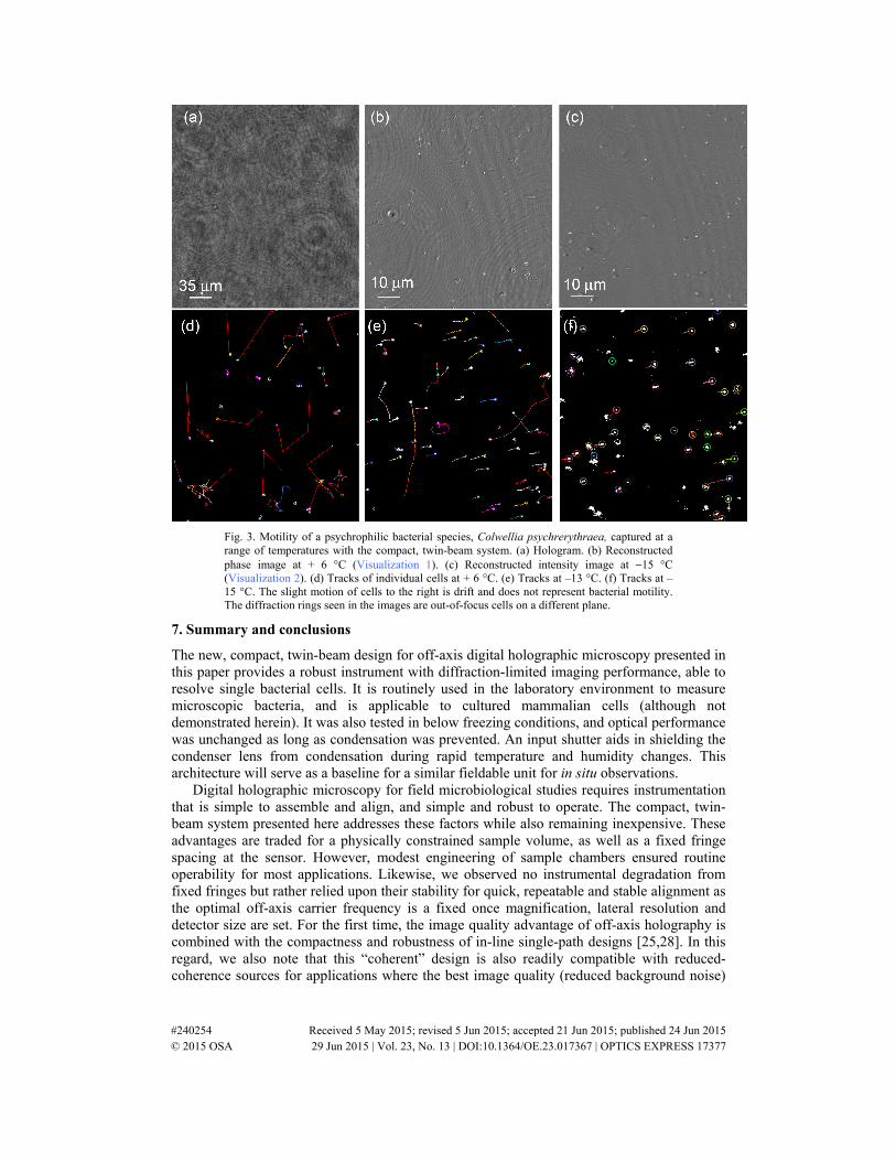
Fig. 3. Motility of a psychrophilic bacterial species, Colwellia psychrerythraea, captured at a range of temperatures with the compact, twin-beam system. (a) Hologram. (b) Reconstructed phase image at + 6 °C (Visualization 1). (c) Reconstructed intensity image at −15 °C (Visualization 2). (d) Tracks of individual cells at + 6 °C. (e) Tracks at –13 °C. (f) Tracks at –15 °C. The slight motion of cells to the right is drift and does not represent bacterial motility. The diffraction rings seen in the images are out-of-focus cells on a different plane.
7. Summary and conclusions
The new, compact, twin-beam design for off-axis digital holographic microscopy presented in this paper provides a robust instrument with diffraction-limited imaging performance, able to resolve single bacterial cells. It is routinely used in the laboratory environment to measure microscopic bacteria, and is applicable to cultured mammalian cells (although not demonstrated herein). It was also tested in below freezing conditions, and optical performance was unchanged as long as condensation was prevented. An input shutter aids in shielding the condenser lens from condensation during rapid temperature and humidity changes. This architecture will serve as a baseline for a similar fieldable unit for in situ observations.
Digital holographic microscopy for field microbiological studies requires instrumentation that is simple to assemble and align, and simple and robust to operate. The compact, twin-beam system presented here addresses these factors while also remaining inexpensive. These advantages are traded for a physically constrained sample volume, as well as a fixed fringe spacing at the sensor. However, modest engineering of sample chambers ensured routine operability for most applications. Likewise, we observed no instrumental degradation from fixed fringes but rather relied upon their stability for quick, repeatable and stable alignment as the optimal off-axis carrier frequency is a fixed once magnification, lateral resolution and detector size are set. For the first time, the image quality advantage of off-axis holography is combined with the compactness and robustness of in-line single-path designs [25,28]. In this regard, we also note that this “coherent” design is also readily compatible with reduced-coherence sources for applications where the best image quality (reduced background noise)
#240254 Received 5 May 2015; revised 5 Jun 2015; accepted 21 Jun 2015; published 24 Jun 2015 © 2015 OSA 29 Jun 2015 | Vol. 23, No. 13 | DOI:10.1364/OE.23.017367 | OPTICS EXPRESS 17377

is required. Because of these advantages, this architecture should find wide use in both the laboratory and field applications.
Acknowledgments
This work was funded by the Gordon and Betty Moore Foundation through grants 4037 to McGill University and 4038 to the California Institute of Technology. We also thank the Keck Institute for Space Studies for allowing us use of the Tolman/Bacher House, which served as a meeting location for our team on the Caltech campus. We appreciate the contribution of Asphericon, Inc. for fabricating customized optical elements to meet the packaging needs. This work was partially carried out by the Jet Propulsion Laboratory, California Institute of Technology.
#240254 Received 5 May 2015; revised 5 Jun 2015; accepted 21 Jun 2015; published 24 Jun 2015 © 2015 OSA 29 Jun 2015 | Vol. 23, No. 13 | DOI:10.1364/OE.23.017367 | OPTICS EXPRESS 17378