robotics: science and systems 2012 sydney, nsw, … · development of a testbed for robotic...
TRANSCRIPT

Robotics: Science and Systems 2012Sydney, NSW, Australia, July 09-13, 2012
1
Development of a Testbed forRobotic Neuromuscular Controllers
Alexander Schepelmann, Michael D. Taylor, Hartmut GeyerThe Robotics Institute
Carnegie Mellon UniversityPittsburgh, Pennsylvania 15213
Email: [email protected], [email protected], [email protected]
Abstract—Current control approaches to robotic legged loco-motion rely on centralized planning and tracking or motion pat-tern matching. Central control is not available to robotic assistivedevices that integrate with humans, and matching predefinedpatterns severely limits user dexterity. By contrast, biologicalsystems show substantial legged dexterity even when their centralnervous system is severed from their spinal cord, indicating thatneuromuscular feedback controls can be harnessed to encodestability, adaptability, and maneuverability into legged systems.Here we present the initial steps to develop a robotic gait testbedthat can implement and verify neuromuscular controls for roboticassistive devices. The initial stage consists of an antagonisticallyactuated two segment leg with a floating compliant joint. Wedetail its electromechanical design and low level, velocity-basedtorque control. Additionally, we present experiments that test theleg’s performance during human-like high fidelity motions. Theresults show that the robot can track fast motions correspondingto 87% of the maximum performance limit of human muscle. Theexperiments also reveal limitations of our current implementationand we discuss solutions to overcoming them.
I. INTRODUCTION
Current approaches to leg control in locomotion either usecentralized planning and tracking or mimic predefined jointmotion patterns extracted from normal human gait. The firstapproach is used in humanoids including Honda’s ASIMO andAIST’s HRP-4 [11][18][27], but cannot be applied to roboticassistance wherein the central human user’s state is unknown.As a result, the second approach prevails in rehabilitationrobotics [17][2][12][13]. For instance, exoskeletons developedfor paralyzed patients enforce a limited set of pre-definedmotion patterns of normal human gait [21][1], which severelyconstrains their functional dexterity. In part, this problemcan be overcome by combining motion libraries and patternrecognition, as Sup et al. [30] demonstrated with a poweredlegged prosthesis for speed and slope adaptation. However,control strategies that generate the stability, maneuverability,and adaptability needed for truly high mobility have not beenidentified with this approach.
We seek to develop an alternative control approach topowered legged systems that builds on decentralized neuro-muscular control strategies of human locomotion. Animal andhuman legs possess remarkable autonomy in behavior andcontrol. For example, decerebrate cats and rats have no braincontrol over their legs, yet they seamlessly adapt to differentlocomotion speeds on a treadmill and autonomously transition
between gaits [28][4][20]. Similar neuro-scientific experimentsreveal that, in biological systems, dexterous performance ofsegmented legs is realized to a large extent by local feedbackcontrols that bypass central processing, and by biomechanicaldesigns that hardcode functional leg responses [5][24][14][7].Recently, neuromuscular models of human locomotion weredeveloped, which are controlled by autonomous local feed-backs without central planning, yet adapt to their environmentand show substantial robustness of locomotion[8][29]. Eilen-berg et al. [6] have implemented part of this feedback controlin a powered ankle-foot prosthesis, resulting in a system thatadapts to the environment without requiring explicit terrainsensing.
To generalize this approach to segmented powered legs,we here present our initial steps of developing a robotic gaittestbed that can implement and test neuromuscular controllersfor robotic assistive devices. The testbed currently consists ofa half-human sized, two segment leg with two antagonistic ac-tuators and a compliant floating joint. We detail the electrome-chanical design and control of this robotic neuromuscular leg(RNL) (sect. II and III), and present and discuss experimentalresults that test the performance of the leg during human-like,high-fidelity motions (sect. IV and V).
II. ELECTROMECHANICAL DESIGN
RNL is a half-human sized, two segmented, antagonisticallyactuated robotic leg with joint compliance (Fig. 1). Theelectromechanical design of RNL is driven by three themes:dynamic similarity, antagonistic actuation, and leg compliance.
A. Dynamic Similarity
We aim to build a testbed that matches human leg per-formance to develop neuromuscular controllers for poweredsegmented legs. For cost and safety considerations we build arobotic leg that is half the size and a quarter of the weight of ahuman leg. To ensure that the dynamic behavior of our robotmatches human legs, we use dynamic scaling. Dynamic scal-ing uses fundamental physical variables to define relationshipsbetween a system’s quantities at different scales. This approachwas formalized by Buckingham [3] and is often applied inaerospace and fluid engineering applications. In mechanicalsystems, fundamental units are mass, length, and time. Therobot’s mass and length targets define these scaling factors
Hamstring SEA
Vastus SEA
Hamstring
Vastus
Gluteus
Hip Flexors
Gastrocnemius
Soleus
Tibialis Anterior
25cm
(a) (c) (d)(b)
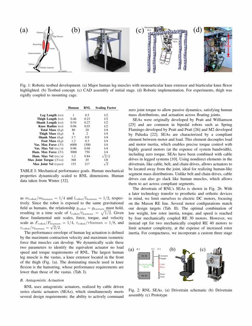
Fig. 1: Robotic testbed development. (a) Major human leg muscles with monoarticular knee extensor and biarticular knee flexorhighlighted. (b) Testbed concept. (c) CAD assembly of initial stage. (d) Robotic implementation. For experiments, thigh wasrigidly coupled to mounting cage.
Human RNL Scaling Factor
Leg Length (m) 1 0.5 1/2Thigh Length (m) 0.46 0.23 1/2Shank Length (m) 0.54 0.27 1/2
Knee Radius (m) 0.06 0.03 1/2Total Mass (kg) 80 20 1/4
Thigh Mass (kg) 8 2 1/4Shank Mass (kg) 3.7 0.9 1/4
Foot Mass (kg) 1.2 0.3 1/4Vas. Max Force (N ) 6000 1500 1/4Vas. Max Vel (m/s) 0.96 0.68 1/4
Ham. Max Force (N ) 3000 750 1/4Ham. Max Vel (m/s) 1.2 0.84
√2/2
Max Joint Torque (Nm) 368 45 1/8Max Joint Vel (rpm) 153 217
√2
TABLE I: Mechanical performance goals. Human mechanicalproperties dynamically scaled to RNL dimensions. Humandata taken from Winter [32].
as mrobot/mhuman = 1/4 and lrobot/lhuman = 1/2, respec-tively. Since the robot is exposed to the same gravitationalfield as humans, the relationship grobot = ghuman must hold,resulting in a time scale of trobot/thuman =
√1/2. Given
these fundamental unit scales, force, torque, and velocityscale as Frobot/Fhuman = 1/4, τrobot/τhuman = 1/8, andvrobot/vhuman =
√2/2.
The performance envelope of human leg actuation is definedby the maximum contraction velocity and maximum isometricforce that muscles can develop. We dynamically scale thesetwo parameters to identify the equivalent actuator no loadspeed and torque requirements of RNL. The largest humanleg muscle is the vastus, a knee extensor located in the frontof the thigh (Fig. 1a). The dominating muscle used in kneeflexion is the hamstring, whose performance requirements arelower than those of the vastus. (Tab. I).
B. Antagonistic Actuation
RNL uses antagonistic actuators, realized by cable drivenseries elastic actuators (SEAs), which simultaneously meetsseveral design requirements: the ability to actively command
zero joint torque to allow passive dynamics, satisfying humanmass distributions, and actuation across floating joints.
SEAs were originally developed by Pratt and Williamson[25] and are common in bipedal robots such as SpringFlamingo developed by Pratt and Pratt [26] and M2 developedby Paluska [22]. SEAs are characterized by a compliantelement between motor and load. This element decouples loadand motor inertia, which enables precise torque control withhighly geared motors (at the expense of system bandwidth),including zero torque. SEAs have been combined with cabledrives in legged systems [10]. Using nondirect elements in thedrivetrain, like cable, belt, and chain drives, allows actuators tobe located away from the joint, ideal for realizing human-likesegment mass distributions. Unlike belt and chain drives, cabledrives can also go slack like human muscles, which allowsthem to act across compliant segments.
The drivetrain of RNL’s SEAs is shown in Fig. 2b. Witha later technology transfer to prosthetic and orthotic devicesin mind, we limit ourselves to electric DC motors, focusingon the Maxon RE line. Several motor configurations matchour design targets (Tab. II). The optimal combination oflow weight, low rotor inertia, torque, and speed is reachedby four mechanically coupled RE 30 motors. However, weinstead opt for two mechanically coupled RE 40 motors tolimit actuator complexity, at the expense of increased rotorinertia. For compactness, we incorporate a custom three stage
Spring
3:14:1
Cable Drive
ActuatorOutput
KneeJoint
3:1
RE 40
RE 40
(a) (b) (c)
Fig. 2: RNL SEAs. (a) Drivetrain schematic (b) Drivetrainassembly (c) Prototype

4x RE 30 2x RE 40
Gear Ratio 40 36Total Weight (g) 952 960
Rotor Inertia (kgm2) 0.0221 0.03Nominal Torque (Nm) 14.1 13.2
Stall Torque (Nm) 163 180No Load Speed (rpm) 212 211Nominal Speed (rpm) 194 194
TABLE II: SEA motor configurations. Optimal configurationis comprised of four RE 30s. Two RE 40s meet the sameperformance criteria with lower mechanical complexity, at theexpense of increased rotor inertia.
(a) (b) (c)
Fig. 3: Floating compliant knee joint. (a) Concept (b) Proto-type (c) Close-up of implementation
drivetrain into our actuation system (Fig. 2a). The first stagemechanically couples the motors with a 4:1 reduction; thesecond stage orients the output shaft’s axis of rotation witha 3:1 reduction. We locate a rotary spring coupling betweenthese stages. Currently, we use an off-the-shelf spring cou-pler (Stock Drive Products) with a stiffness of 1.75Nm/radand a maximum torque rating of 1.4Nm. An additional 3:1reduction is located between the SEA output shaft and joint,connected via cable drive, for a total 36:1 gear reduction in ourdrivetrain. The gear ratio of the external stage can be modified,which allows us to use the same SEA for muscles withdifferent properties. We realize force measurements via twoabsolute rotary encoders (RM22B: 9bit, magnetic, analogueencoders; Renishaw PLC) located on either side of the spring.Additionally, an incremental encoder on the shaft of one RE40 measures motor velocity (RM22I: 9bit, magnetic, digitalencoder; Renishaw PLC). One motor controller (Solo Whistle,Elmo MC) supplies the same current to both RE 40s. CurrentlyRNL uses two SEAs. One is located in the robot’s thigh,simulating the vastus muscle; the other is located on themounting frame, simulating the biarticular hamstring muscle(Fig. 1c).
C. Leg Compliance
Humans are not rigidly coupled kinematic chains, possess-ing interjoint cartilage and soft tissue around bones. To capturethis aspect in RNL, we incorporate a floating joint designinto the robot (Fig. 3). The floating joint design connectsthe robot’s thigh and shank. The joint is composed of tworapid prototyped clamping plates (VeroWhitePlus, Objet Ltd.),
which hold the compliant element. The compliant element ismade from a two-part PMC-744 urethane rubber mix (Smooth-on Inc.), which is cast into the clamping plates. A complianceretainer, constructed from a brass spur gear, couples the joint’sshaft and compliant element, and defines the floating centerof rotation of the knee joint’s axis. The retainer’s set screwrigidly couples the thigh and joint shaft. This design restrictsrotational motion to only occur in the robot’s shank. AnRM22B encoder head is mounted on the joint shaft. Thecorresponding encoder body is located on the shank. Relativemotion between the encoder head and body measures kneeposition during leg movement.
III. VELOCITY-BASED SEA CONTROL
Our actuators generate desired torques using a velocity-based SEA control scheme [31]. Pratt and Williamson [25]originally approached SEA control from a torque-based per-spective. Recently, an alternative SEA controller was proposedby Wyeth [33], which modulates load torque, τl, using motorvelocity, ωm, as a control target instead of motor torque,
ωm = τl
(1
Jls+
s
ks
), (1)
where Jl is the load inertia and ks is the stiffness of thecompliant element. This approach is advantageous becauselosses due to gear dynamics between the motor and spring donot need to be considered. Since motor velocity correspondsexactly to velocity at the drivetrain output, the velocity loopautomatically compensates for losses without additional tuningof the outer control loop. In addition, the controller’s inversedynamics terms (Fig. 4) only require the first derivative ofmotor position, which leads to increased system bandwidth,since low-pass filters with higher cutoff frequencies can beused.
Wyeth [33]’s formulation of velocity-based SEA control (eq.1) requires load inertia to be known. For legged systems, itis not clear what the load inertia is, as load dynamics con-stantly change due to joint position and gait phase. However,knowledge of load inertia is not necessary in the formulationof a velocity-based SEA controller. Starting with Pratt andWilliamson [25]’s derivation, torque exerted by a spring dueto angular deflection is given as
τl = −ks(θl − θm) (2)
where τl is the torque applied to the load, ks is the springstiffness, and (θl-θm) defines the deflection of the spring be-tween the load and motor side. To formulate torque control asvelocity-based control, we write motor position as a functionof motor velocity θm = ωm/s, and resolve eq. 2 to
ωm = τl/kss+ θls. (3)
Here Jl does not need to be known. Fig. 4 shows a schematicimplementation of this velocity control, in which eq. 3 hasbeen implemented as feedforward compensation, P (s) is PDfeedback compensation for model uncertainty, and C(s) rep-resents the motor controller.
1/ks
P(s)
s
C(s) 1/sωmd ωm θm
ks
s
θlτd ++-
-+
τlProcess Dynamics ModelVelocity-Based Torque Controller
Mec
hani
cal I
nter
face
Beh
avio
r C
ontr
olle
r
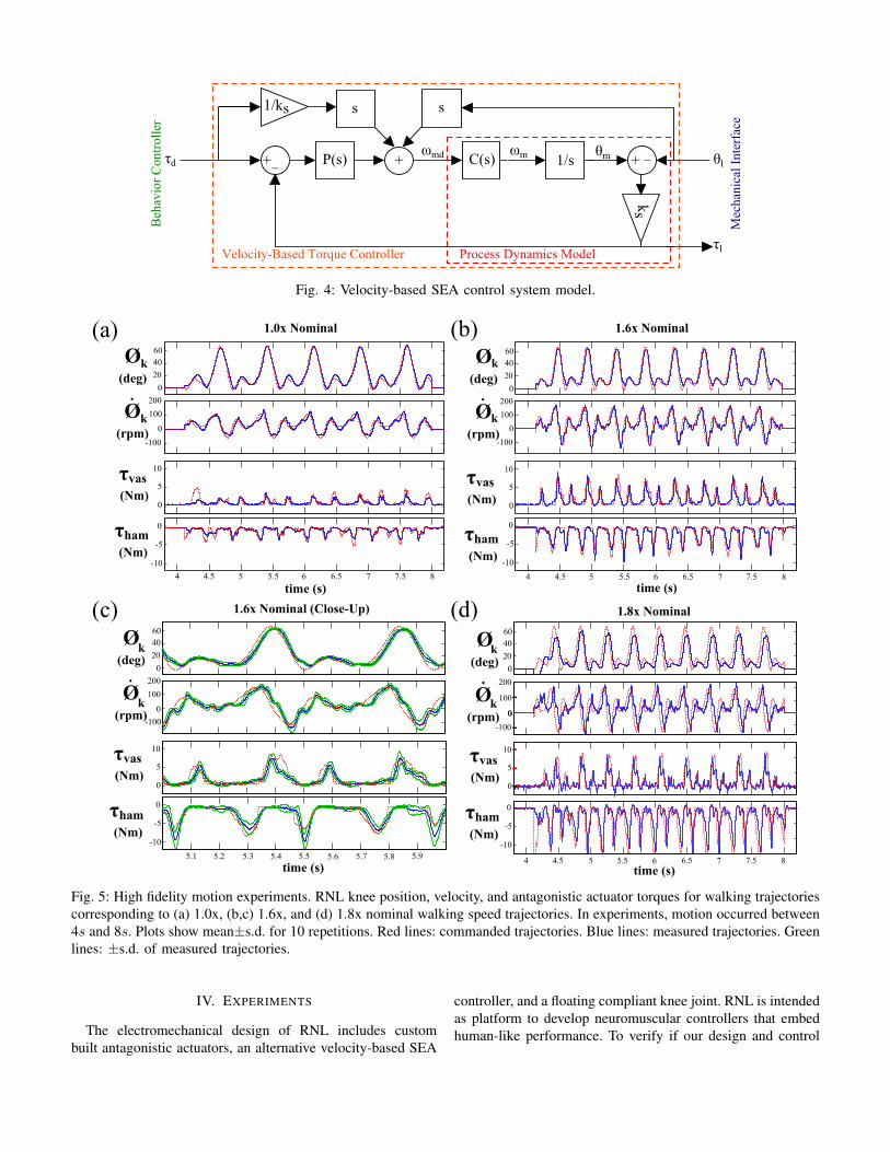
Fig. 4: Velocity-based SEA control system model.
20
0
4060
0
Ø(rpm)
k
-100
100
200
0
5
10
-10
-5
0
4 4.5 5 6 7 85.5 6.5 7.5
time (s)
τham (Nm)
τvas (Nm)
1.0x Nominal
Ø(deg)
k
(a)
20
0
4060
0
-100
100
200
0
5
10
-10
-5
0
4 4.5 5 6 7 85.5 6.5 7.5
time (s)
τham (Nm)
τvas (Nm)
1.6x Nominal
Ø(rpm)
Ø(deg)
k
k
(b)
Ø(rpm)
Ø(deg) 20
0
4060
0
-100
100
200
0
5
10
-10
-5
0
5.1 5.2 5.4 5.6 5.85.3 5.5 5.7 5.9
time (s)
τham (Nm)
τvas (Nm)
1.6x Nominal (Close-Up)
k
k
(c)
Ø(rpm)
Ø(deg)
time (s)
τham (Nm)
τvas (Nm)
1.8x Nominal
k
20
0
4060
0
0
k
4 4.5 5 6 7 85.5 6.5 7.5
5
10
-10
-5
0
0
-100
100
200
(d)
Fig. 5: High fidelity motion experiments. RNL knee position, velocity, and antagonistic actuator torques for walking trajectoriescorresponding to (a) 1.0x, (b,c) 1.6x, and (d) 1.8x nominal walking speed trajectories. In experiments, motion occurred between4s and 8s. Plots show mean±s.d. for 10 repetitions. Red lines: commanded trajectories. Blue lines: measured trajectories. Greenlines: ±s.d. of measured trajectories.
IV. EXPERIMENTS
The electromechanical design of RNL includes custombuilt antagonistic actuators, an alternative velocity-based SEA
controller, and a floating compliant knee joint. RNL is intendedas platform to develop neuromuscular controllers that embedhuman-like performance. To verify if our design and control

Fig. 6: RNL knee position and antagonistic actuator torque during co-contraction experiments for (a) 0% (b) 5% (c) 10% (d)15%. Red lines: commanded trajectory. Blue lines: measured trajectory. Green lines: External impulse disturbances to instigateshank oscillation.
implementations meet this performance, we devise two experi-ments. The first experiment tests if the robot can generate fast,high fidelity motions that characterize human locomotion. Thesecond experiment targets the ability to execute antagonisticco-contraction often seen in neuromuscular control.
Since RNL currently only has actuators simulating thehamstring and vastus, we focus on the robot’s knee for thisevaluation. To simulate the inertial effects of a foot segment,we attach a weight to the bottom of RNL’s shank, increasingits total mass to 1.1kg. The resulting mechanical properties ofthe shank segment are lcom = 0.107m and Js = 0.005kgm2,where lcom is the distance of the shank’s center of massposition from the knee pivot and Js is the inertia.
A. High Fidelity Motion Experiments
We evaluate RNL’s motion fidelity using dynamically scaledhuman joint trajectories. We first numerically differentiateknee angular position data, φrefk , tabulated in Winter [32] togenerate reference trajectories for joint velocity, φrefk , and ac-celeration, φrefk , observed in human walking. The trajectoriesare median filtered (filter order = 10) to eliminate artifactsresulting from the differentiation. Next, we use dimensionalscaling to adapt the trajectories to RNL’s scale. The resultingjoint trajectories correspond to normal human walking speed(1.0x nominal trajectory). We scale these trajectories to range
between 1.0x and 2.0x speed of the nominal trajectory, thelatter of which reaches maximum knee joint velocity (Tab. I).
With these references, we implement a tracking controlthat outputs desired actuator torques. The controller includesfeedforward torque trajectories, Jsφ
refk , gravity compensation,
and PD feedback compensation, kp(φrefk −φk)+kd(φ
refk −φk),
where kp = 15 and kd = 0.01kp are the position and velocityfeedback gains. The gains are kept constant throughout allexperiments. φk and φk are measured by the absolute encoderon RNL’s knee joint. The four components are summed togenerate net joint torque. The resulting actuator flexion andextension torques are commanded to the corresponding SEAvia the velocity-based control scheme described in section III.To avoid cable slack, each SEA applies a minimum 0.5Nmtorque to the joint at all times. Fig. 5 summarizes the results ofthe motion experiments. Tabs. III and IV list the mean cross-correlation coefficients and signal time delays over the trialsfor all traces. We observe that the executed joint position andvelocity trajectories closely follow the desired trajectories fortrials up to 1.6x, with position and velocity correlation coef-ficients greater than 0.90 and 0.80, respectively. The largestdifferences between desired and commanded position occurduring periods of knee extension at 1.6x, with a maximumerror of 7.3◦. Velocity shows a similar tracking quality. Topspeeds achieved 160rpm in 1.6x trials. In addition, we observe

Rθk RθkRτvas Rτham
1.0x 0.97±0.01 0.87±0.04 0.71±0.06 0.90±0.021.2x 0.97±0.01 0.88±0.02 0.67±0.04 0.90±0.021.4x 0.94±0.02 0.82±0.04 0.80±0.02 0.82±0.051.6x 0.95±0.02 0.85±0.02 0.80±0.01 0.80±0.031.8x 0.80±0.06 0.64±0.08 0.77±0.04 0.62±0.04
TABLE III: Mean correlation coefficients (R) for walkingtrials. n =10 for all speeds.
tθk tθktτvas tτham
1.0x 9.5±1.5 18.4±2.6 13.1±1.7 4.8±0.91.2x 7.2±0.9 11±0.7 10.3±1.2 5.1±0.71.4x 15.9±1.4 19.5±1.8 9.1±1.0 9.0±1.61.6x 12.3±2.4 15.2±2.3 10.7±0.8 9.3±1.71.8x 25.0±3.9 25.2±4.4 9.5±2.1 14.9±0.9
TABLE IV: Mean time delays (t) in ms for walking trials.n =10 for all speeds.
a high degree of repeatability throughout all trials, with amaximum standard deviation of 7.4◦ and 44rpm from themean values over all trials1. The results indicate that human-like segment motions can be reliably and accurately replicatedfor speeds up to 160rpm.
At higher speed trials, the quality of position and velocitytracking declines (Tabs. III and IV). Nevertheless, velocitytargets were still reached with top speeds of at least 190rpm(Fig. 5d), or about 87% of our desired performance goalsoutlined in Tab. I. We could not test higher speeds, becausethe compliance retainer in the knee joint failed during the highspeed trials.
B. Co-Contraction ExperimentsAntagonistic muscle co-contraction is characterized by
equal pre-load torques of the muscles, τPL, and an equivalentrotational joint stiffness, kknee. The corresponding desiredSEA torques are given by
τvas/ham = τPL ± kknee (φk − φ0) (4)
where φ0 is the joint reference position. To estimate appro-priate values for τPL and kknee, we use a Hill-type musclemodel as described in Geyer et al. [9]. In these models, themuscle force, F , is given by
F = AflfvFisomax (5)
where A is percentage of muscle activation, Fmaxiso is the
muscle’s maximum isometric force, and fl and fv are theforce-length and force-velocity relationships. Combined withthe knee joint radius, the muscle force defines τPL. Forcalculating the local stiffness, we neglect modulations by fvand model fl as
fl = exp
[ln(0.05)
∣∣∣∣ lCE − lopt0.056lopt
∣∣∣∣3]
(6)
1The first leg swing was not included in this calculation, as impulseaccelerations from rest is not representative of system dynamics.
A (%) kmuscle (N/m) τPL (Nm) kknee (Nm/rad)
0 0 0 05 7310 1.22 6.59
10 14640 2.44 13.1715 21950 3.66 19.79
TABLE V: Equivalent stiffnesses & SEA pre-load torques atdifferent muscle activation levels. Values calculated at lCE =1/2lopt.
0% 5% 10%
T Simulation (s) 0.78 0.30 0.22T RNL (s) 0.75±0.04 0.25±0.01 0.25±0.02
TABLE VI: Period of oscillation at different levels of co-contraction.
where lCE is the length of the muscle’s contractile elementand lopt is its optimal length. The resulting muscle stiffness is
kmuscle = AdfldlCE
F isomax. (7)
Using scaled values of the vastus complex (lopt=0.04,w=0.056), we calculate kmuscle, τPL, and kknee, for fourlevels of A, ranging from 0 % to 15% muscle activation. (Tab.V).
If RNL can successfully execute co-contraction, the motionresulting from the torques described by eq. 4 matches themotion of a physical driven pendulum whose center of massand inertia properties correspond to those of the shank. We testthe quality of co-contraction control by deflecting the shankfrom its rest position φ0 = 0 and comparing the resultingbehavior to that of a simulated, equivalent driven physicalpendulum.
Fig. 6 shows the behavior of RNL during the co-contractionexperiments. Fig. 6a shows the observed motion and torquesfor 0% co-contraction, which evaluates the quality of RNL’szero torque control. The shank follows the motion of a dampedpendulum with a period T that matches the simulated period(Tab. VI). For 0% co-contraction, the desired τvas/ham iszero. The measured torques track the commanded torquewithin torque resolution limits of the SEAs. (±0.1Nm jointtorque resolution for SEA spring stiffness of 1.75Nm and9bit encoders.) Higher levels of co-contraction are possible(Fig. 6b-d), but the commanded torques are not well tracked,as large oscillations result from the antagonistic actuatorscounteracting each other with large pre-load torques. Becausethe oscillations exceed the maximum torque rating of ourspring at approximately 15% co-contraction, we cannot com-mand higher levels of co-contraction. This shortcoming of ourcurrent implementation of antagonistic control is visible in theposition trajectories as well.
V. DISCUSSION & CONCLUSION
Our goal is to develop neuromuscular controllers for pow-ered segmented legs. To realize this goal, we presented the
initial design and validation stage of a robotic test platformtargeting human-like performance. The platform currentlyconsists of RNL, a half-human sized, two segment roboticleg with a floating compliant knee joint (Fig. 1d). The elec-tromechanical design of the leg meets the physical weight-size properties and actuation performance defined by humanphysiology. To meet these criteria, we developed a modular,compact SEA (Fig. 2) that matches the performance of thevastii, the largest muscle group in human legs. In addition, weformulated an SEA control that takes advantage of velocity-based torque control without having to know load inertia (Fig.4).
In two experiments, we tested if our design and controlimplementation can deliver fast motions that characterize hu-man locomotion and can generate antagonistic co-contractionseen in neuromuscular systems. The experimental results showthat we can reliably generate human-like leg motions withhigh positional accuracy for joint speeds up to 160rpm andwith lesser positional accuracy for joint speeds up to 190rpm(Fig. 5), approximately 90% of the maximum designed forjoint velocity (Tab. I). The failure of the knee joint’s clampingplates during the high speed experiments indicates that theprototyped plates will need to be replaced by stronger materialversions to achieve these maximum speeds. On the other hand,the compliant part of the floating joint did not show any wearthroughout the experiments, suggesting that its design worksvery well. The co-contraction experiments revealed that theantagonistic actuators can command zero torque within thetorque resolution limits of the SEAs, enabling near passivemotions at the joint level (Fig. 6a). Higher levels of co-contraction up to 15% of human muscle activations werepossible, but produced oscillations in the SEA torque patternswhich limited the performance of co-contraction control.
The experiments revealed two shortcomings of our currentimplementation, which we are working on overcoming. First,the actuators’ bandwidth limitation creates about 25ms oftime delay during high speed position and velocity tracking.Scaled to human dimensions, this delay would be about 35ms,which is similar to the feedback delays observed in humans.However, the SEA delay will increase substantially with largeractuation levels necessary for stance motions. To diminishthe delay, we are looking to replace the linear rotary springin the actuators with a nonlinear stiffening spring. Stiffeningsprings in SEAs enable high precision zero torque control withhigh bandwidth responses at large commanded torques. Theadvantages of nonlinear springs to series elastic actuation arewidely recognized (Pratt and Williamson [25], Hurst et al.[15], Migliore et al. [19]), although a systematic methodfor developing compact springs with custom force deflectionprofiles has not been proposed. In addition, a custom nonlinearspring coupler will also allow us to overcome the currenttorque limit of 12.6Nm at the output that is defined by themaximum torque capacity of the off-the-shelf springs in theSEAs.
The second shortcoming is the 15% limit on co-contractioncontrol. The impact of this limit on implementing neuromus-
cular control strategies is unclear. While humans can reach upto 30% of antagonistic co-contraction at the leg joints [23],these levels are observed during the stance phase in which thelegs are loaded by body weight, which is about 17 times largerthan the weight of the shank. In the experiments, by contrast,the leg was unloaded and resistance to motion was entirelydue to the mass properties of the shank. In particular, alreadyat 5% co-contraction the peak torques of the actuators reached3.2Nm, which corresponds to the torque created by one bodyweight. Hurst et al. [16] suggest that damping elements parallelto the SEA spring may attenuate oscillations when load inertiais low. We plan to test if adding such elements into the SEAdrivetrain will improve the quality of co-contraction control.
The presented robot validates our initial design and controlimplementation, but does not represent a full neuromuscularleg. We are currently expanding RNL into a multi-degreeof freedom leg with hip, knee, and ankle joints as well asan adaptive, compliant foot. This robot will incorporate 7actuators based on our presented SEA design and controlimplementation. These actuators represent the major mono-and bi-articular muscles that propel human legs during walkingand running. The actuators will be controlled by reflexiveneuromuscular models [8] [29], which will generate desiredtorques for each SEA unit (τd in Fig. 4). With this robot, theimmediate goal will be to realize reflexive leg controls duringswing, crucial for autonomous balance recovery in amputeelocomotion. Ultimately, we expect this work to result in ageneralized gait testbed to develop and test neuromuscularcontrollers for multi-articulated powered robotic limbs forrehabilitation and humanoid robotics.
ACKNOWLEDGMENTS
This work is supported by the Richard King Mellon Foun-dation. A.S. is supported by the National Science FoundationGraduate Research Fellowship Program. The authors wish tothank Larry Hayhurst and David Matten for their help withrobot construction. We also wish to thank Daniel Haufle forhis help with hardware communication.
REFERENCES
[1] S.K. Agrawal, S.K. Banala, K. Mankala, V. Sangwan, J.P.Scholz, V. Krishnamoorthy, and W.L. Hsu. Exoskeletonsfor gait assistance and training of the motor impaired.Proc IEEE Int Conf Rehab Robo, pages 1108–1113,2007.
[2] H.K. Au, H. Herr, J. Weber, and E.C. Martinez-Villalpando. Powered ankle-foot prosthesis for the im-provement of amputee ambulation. Conf Proc IEEE EngMed Biol Soc, pages 3020–3026, 2007.
[3] E. Buckingham. On physically similar systems; illustra-tions of the use of dimensional equations. Phys Rev, 4:345–376, 1914.
[4] G. Courtine, Y. Gerasimenko, R. van den Brand, A. Yew,P. Musiekno, H. Zhong, B. Song, Y. Ao, R.M. Ichiyama,I. Lavrov, R.R. Roy, M.V. Sofroniew, and V.R. Edgerton.

Transformation of nonfunctional spinal circuits inot func-tional states after the loss of brain input. Nat Neurosci,12(10):1333–1342, 2009.
[5] V. Dietz. Proprioception and locomotor disorders. NatRev Neurosci, 3(10):781–790, 2002.
[6] M.F. Eilenberg, H. Geyer, and H. Herr. Control of apowered ankle-foot prosthesis based on a neuromuscularmodel. IEEE Trans Neural Sys Rehab Eng, 18(2):164–173, 2010.
[7] Y. Gerasimenko, R.R. Roy, and V.R. Edgerton. Epiduralstimulation: comparison of the spinal circuits that gen-erate and control locomotion in rats, cats and humans.Experimental Neurology, 209(2):417–425, 2008.
[8] H. Geyer and H. Herr. A muscle-reflex model thatencodes principles of legged mechanics produces humanwalking dynamics and muscle activities. IEEE TransNeural Sys Rehabil Eng, 2010.
[9] H. Geyer, Seyfarth A., and R. Blickhan. Positive forcefeedback in bouncing gaits? Proc R Soc B, 270:2173–2183, 2002.
[10] J.W. Grizzle, J. Hurst, B. Morris, H.W. Park, andK. Sreenath. Mabel, a new robotic bipedal walker andrunner. American Control Conference, pages 2030–2036,2009.
[11] M. Hirose and K. Ogawa. Honda humanoid robotsdevelopment. Phil Trans R Soc A, 365(1850):11–19,2007.
[12] J. Hitt, A.M. Oymagil, T. Sugar, K. Hollander, BoehlerA., and J. Fleeger. Dynamically controlled ankle-foot or-thosis (dco) with regenerative kinematics: incrementallyattaining user portability. Proc IEEE ICRA, pages 1541–1546, 2007.
[13] M.A. Holgate, A.W. Boehler, and T. Sugar. Control algo-rithms for ankle robots: a reflection on the state-of-the-art and presentation of two novel algorithms. IEEE/RAS-EMBS Int Conf Biomed Rob and Biomech, pages 97–102,2008.
[14] H. Hultborn and J.B. Nielsen. Spinal control of loco-motion - from cat to man. Acta Physiologica, 189(2):111–121, 2007.
[15] J.W. Hurst, J.E. Chestnutt, and A.A. Rizzi. An actuatorwith physically variable stiffness for highly dynamiclegged locomotion. Proc IEEE ICRA, pages 4662–4667,2004.
[16] J.W. Hurst, A.A. Rizzi, and D. Hobbelen. Series elasticactuation: Potential and pitfalls. Proc Int Conf. ClimbWalk Robots, pages 1–6, 2004.
[17] R. Jimenez-Fabian and O. Verlinden. Review of controlalgorithms for robotic ankle systems in lower-limb or-thoses, prostheses, and exoskeletons. Med Eng Phys, 34(4):397–408, 2012.
[18] S. Kajita, T. Nagasaki, K. Kaneko, and H. Hirukawa.Zmp-based biped running control. IEEE Robotics andAutomation Magazine, 14(2):63–72, 2007.
[19] S.A. Migliore, E.A. Brown, and S.P. DeWeerth. Novelnonlinear elastic actuators for passively controlling
robotic joint compliance. J Mech Des, 129(4):406–412,2007.
[20] P. Musienko, R. van den Brand, O. Maerzendorfer, R.R.Roy, Y. Gerasimenko, V.R. Edgerton, and G. Cour-tine. Controlling specific locomotor behaviors throughmultidimensional monoaminergic modulation of spinalcircuitries. J Neurosci, 31(25):9264–9278, 2011.
[21] P.D. Neuhaus, J.H. Noorden, T.J. Craig, J. Kirschbaum,and J.E. Pratt. Design and evaluation of mina: A roboticorthosis for paraplegics. Proc IEEE ICORR, pages 1–8,2011.
[22] D.J. Paluska. Design of a humanoid biped for walkingresearch. MS Thesis, Massachusetts Institute of Technol-ogy, 2000.
[23] J. Perry and J.M. Burnfield. Gait analysis: Normal andpathological function. SLACK Incorporated, 2, 2010.
[24] E. Pierrot-Desseilligny and D. Burke. The circuitry ofthe human spinal cord: its role in motor control andmovement disorders. Cambridge University Press, 2005.
[25] G.A. Pratt and M.M. Williamson. Series elastic actuators.Proc IEEE/RSJ IROS, 1:399–406, 1995.
[26] J.E. Pratt and G.A. Pratt. Intuitive control of a planarbipedal walking robot. Proc IEEE ICRA, 3:2014–2021,1998.
[27] M. Raibert. Legged robots that balance. MIT Press,Cambridge, 1986.
[28] M.L. Shik, F.V. Severin, and G.N. Orlovski. Control ofwalking and running by means of electric stimulation ofthe midbrain. Biofizika, 11(4):659–666, 1966.
[29] S. Song and H. Geyer. Adaptation of local feedbackcontrol for large speed transitions in human-like walking.Proc IEEE ICRA, 2012.
[30] F. Sup, H.A. Varol, and M. Goldfarb. Upslope walkingwith a powered knee and ankle prosthesis: initial resultswith an amputee subject. IEEE Trans Neural Syst RehavilEng, 19(1):71–78, 2011.
[31] M.D. Taylor. A compact series elastic actuator forbipedal robots with human-like dynamic performance.MS Thesis, Carnegie Mellon University, 2011.
[32] D.A. Winter. Biomechanics and motor control of humanmovement. Wiley, (4), 2009.
[33] G. Wyeth. Control issues for velocity sourced serieselastic actuators. Proc IEEE ICRA, 2006.