robotics lecture 01 - liacs.leidenuniv.nl
TRANSCRIPT
2/15/2021
1
Robotics
Erwin M. Bakker| LIACS Media Lab 15-2 2021
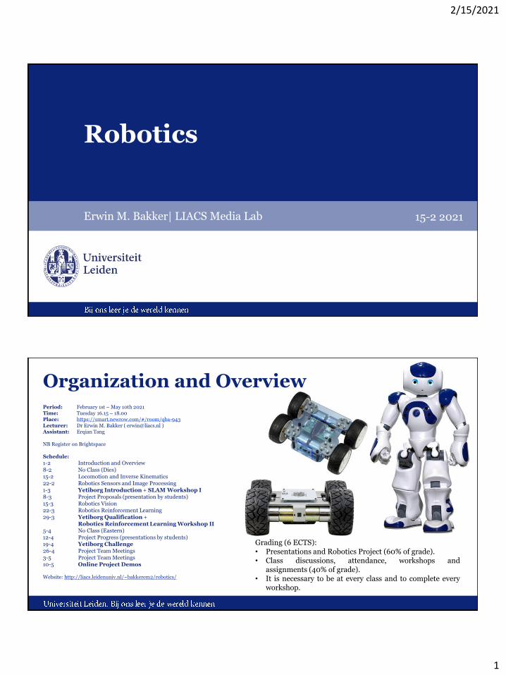
Organization and OverviewPeriod: February 1st – May 10th 2021Time: Tuesday 16.15 – 18.00Place: https://smart.newrow.com/#/room/qba-943Lecturer: Dr Erwin M. Bakker ( [email protected] )Assistant: Erqian Tang
NB Register on Brightspace
Schedule:
1-2 Introduction and Overview8-2 No Class (Dies)15-2 Locomotion and Inverse Kinematics22-2 Robotics Sensors and Image Processing1-3 Yetiborg Introduction + SLAM Workshop I8-3 Project Proposals (presentation by students)15-3 Robotics Vision22-3 Robotics Reinforcement Learning 29-3 Yetiborg Qualification +
Robotics Reinforcement Learning Workshop II5-4 No Class (Eastern)12-4 Project Progress (presentations by students)19-4 Yetiborg Challenge26-4 Project Team Meetings3-5 Project Team Meetings10-5 Online Project Demos
Website: http://liacs.leidenuniv.nl/~bakkerem2/robotics/
Grading (6 ECTS):• Presentations and Robotics Project (60% of grade).• Class discussions, attendance, workshops and
assignments (40% of grade).• It is necessary to be at every class and to complete every
workshop.
2/15/2021
2
Overview
• Robotic Actuators
• Configuration Space
• Rigid Body Motion
• Forward Kinematics
• Inverse Kinematics
• Link: http://modernrobotics.org
K.M. Lynch, F.C. Park, Modern Robotics: Mechanics, Planning and Control, Cambridge University Press, 2017
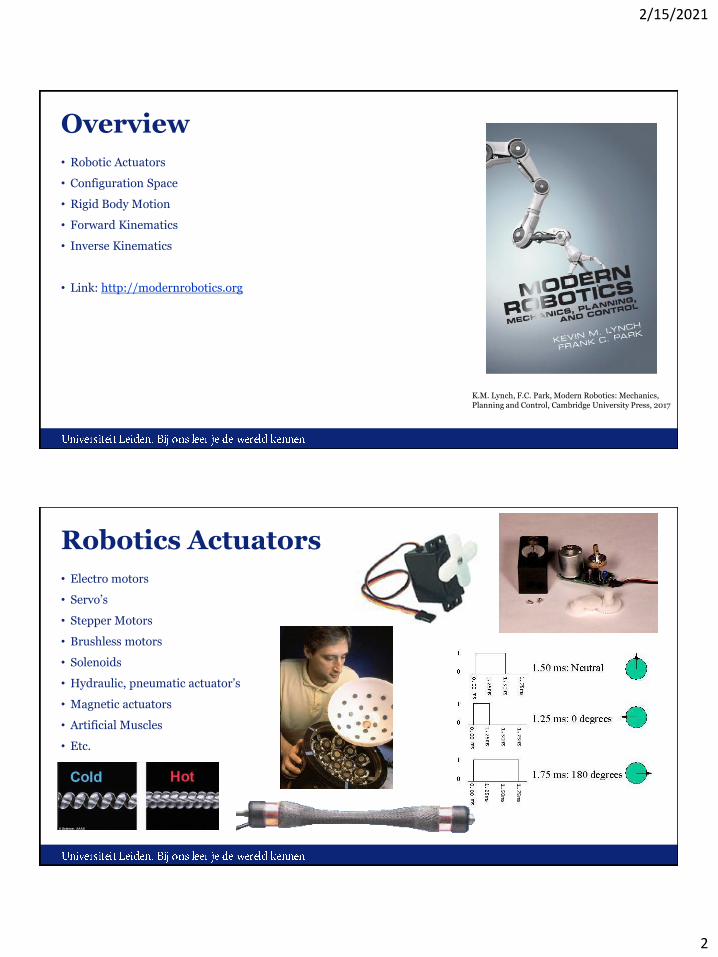
Robotics Actuators
• Electro motors
• Servo’s
• Stepper Motors
• Brushless motors
• Solenoids
• Hydraulic, pneumatic actuator’s
• Magnetic actuators
• Artificial Muscles
• Etc.
2/15/2021
3
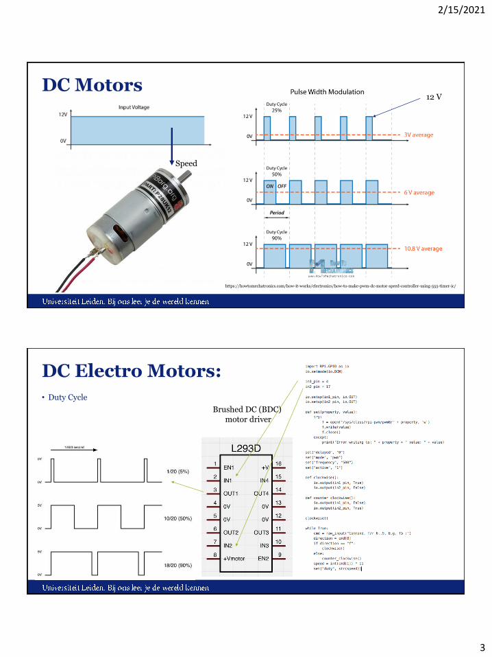
DC Motors
https://howtomechatronics.com/how-it-works/electronics/how-to-make-pwm-dc-motor-speed-controller-using-555-timer-ic/
Speed
12 V
DC Electro Motors:
• Duty Cycle
Brushed DC (BDC) motor driver
2/15/2021
4
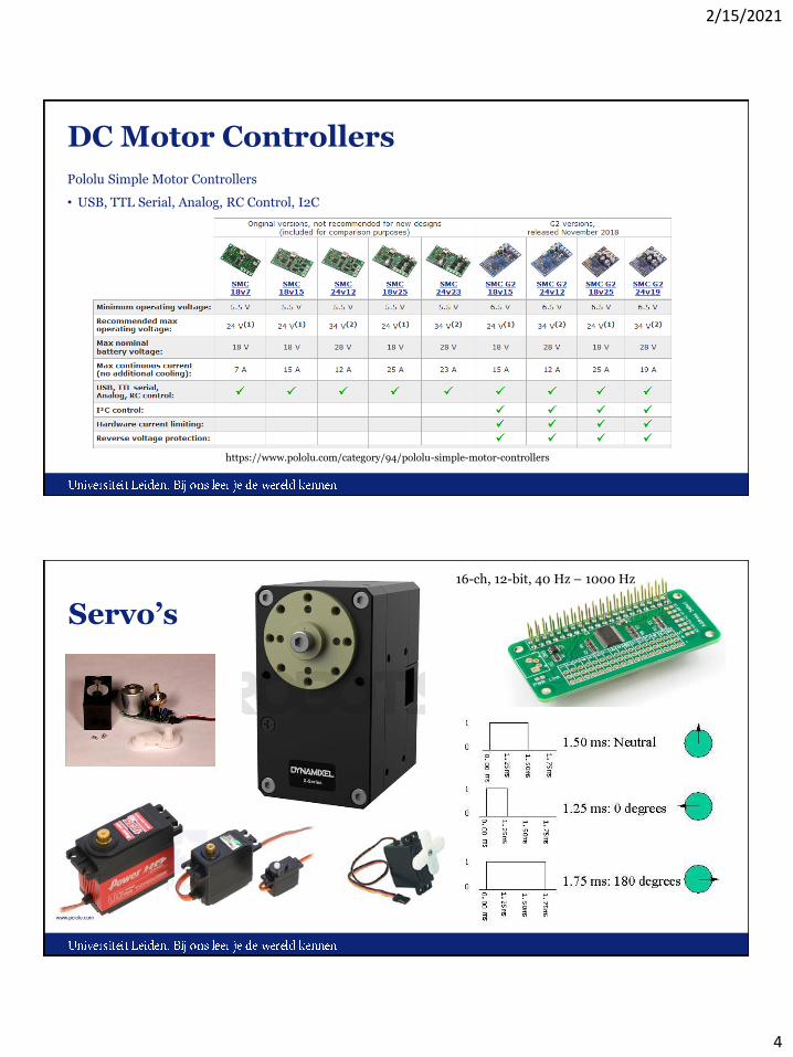
DC Motor Controllers
Pololu Simple Motor Controllers
• USB, TTL Serial, Analog, RC Control, I2C
https://www.pololu.com/category/94/pololu-simple-motor-controllers
Servo’s
16-ch, 12-bit, 40 Hz – 1000 Hz

2/15/2021
5
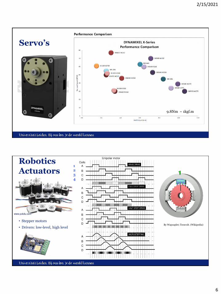
Servo’s
16-ch, 12-bit, 40 Hz – 1000 Hz
Dynamixel Servo’s
2/15/2021
6
Servo’s
9.8Nm ~ 1kgf.m
Robotics Actuators
• Stepper motors
• Drivers: low-level, high levelBy Wapcaplet; Teravolt. (Wikipedia)
1234
2/15/2021
7
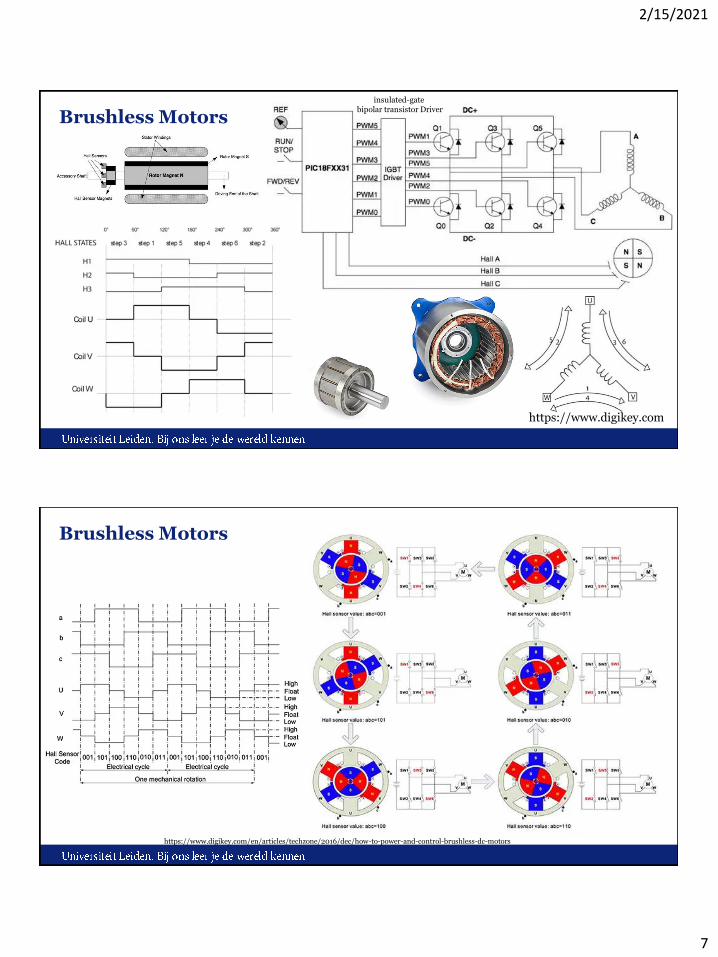
Brushless Motors
https://www.digikey.com
insulated-gate bipolar transistor Driver
Brushless Motors
https://www.digikey.com/en/articles/techzone/2016/dec/how-to-power-and-control-brushless-dc-motors
2/15/2021
8
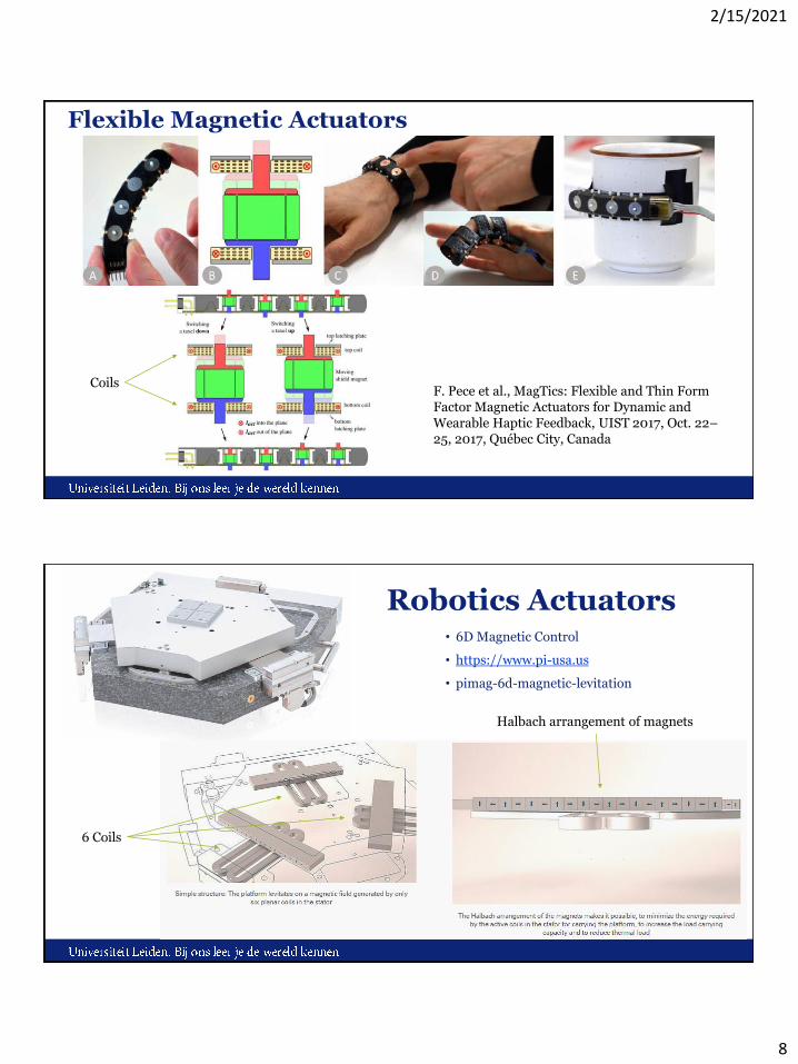
Flexible Magnetic Actuators
F. Pece et al., MagTics: Flexible and Thin Form Factor Magnetic Actuators for Dynamic and Wearable Haptic Feedback, UIST 2017, Oct. 22–25, 2017, Québec City, Canada
Coils
Robotics Actuators• 6D Magnetic Control
• https://www.pi-usa.us
• pimag-6d-magnetic-levitation
6 Coils
Halbach arrangement of magnets
2/15/2021
9
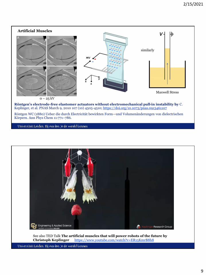
Röntgen’s electrode-free elastomer actuators without electromechanical pull-in instability by C. Keplinger, et al. PNAS March 9, 2010 107 (10) 4505-4510; https://doi.org/10.1073/pnas.0913461107
Röntgen WC (1880) Ueber die durch Electricität bewirkten Form—und Volumenänderungen von dielectrischen Körpern. Ann Phys Chem 11:771–786.
0 – 25 kV
Maxwell Stress
similarly
Artificial Muscles
See also TED Talk The artificial muscles that will power robots of the future byChristoph Keplinger https://www.youtube.com/watch?v=ER15KmrB8h8
2/15/2021
10
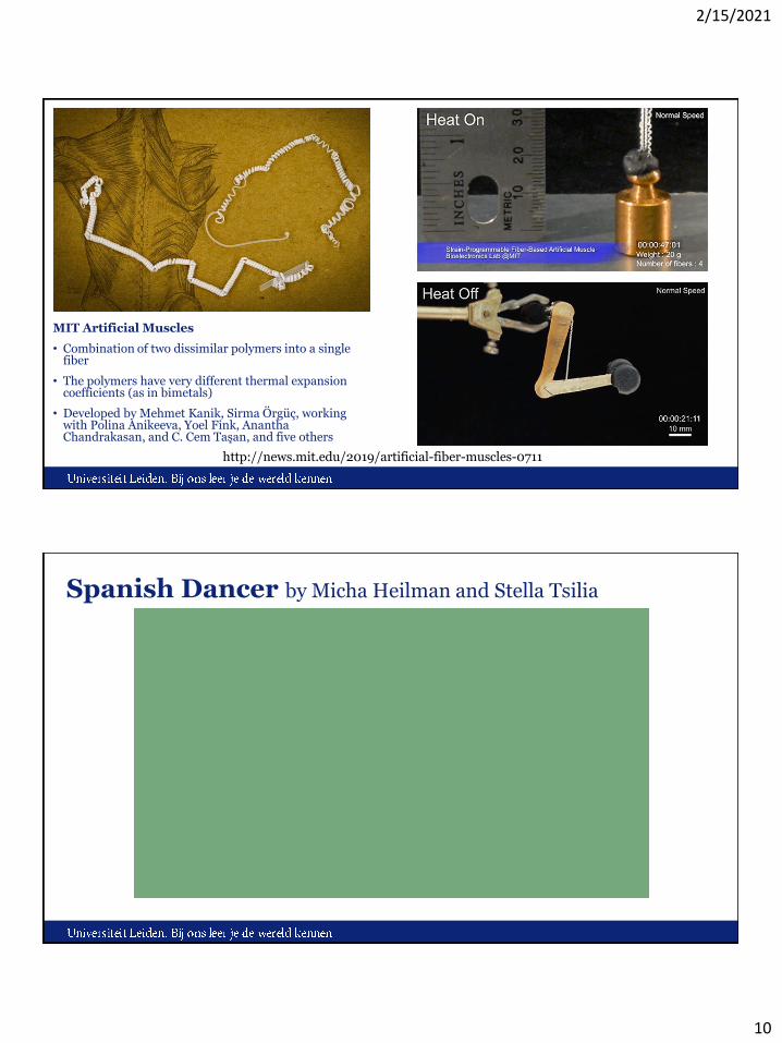
MIT Artificial Muscles
• Combination of two dissimilar polymers into a single fiber
• The polymers have very different thermal expansion coefficients (as in bimetals)
• Developed by Mehmet Kanik, Sirma Örgüç, working with Polina Anikeeva, Yoel Fink, AnanthaChandrakasan, and C. Cem Taşan, and five others
http://news.mit.edu/2019/artificial-fiber-muscles-0711
Spanish Dancer by Micha Heilman and Stella Tsilia

2/15/2021
11
N. Charles, M. Gazzola, and L. Mahadevan, Topology, Geometry, and Mechanics of Strongly Stretched and Twisted Filaments: Solenoids, Plectonemes, and Artificial Muscle Fibers PHYSICAL REVIEW LETTERS 123, 208003 (2019)
Twist density
twistwrithe
Link = Tw + Wr
NAO
http://doc.aldebaran.com/2-1/family/nao_dcm/actuator_sensor_names.html
2/15/2021
12
Hexapod: S.P.I.N. by M. Huijben, M. Swenne, R. Voeter, S. Alvarez Rodriguez.
2/15/2021
How to move to a goal?
Problem: How to move to a goal?
• Grasp, Walk, Stand, Dance, Follow, etc.
Solution:
1. Program step by step
- Computer Numerical Control (CNC), Automation.
2. Inverse kinematics:
- take end-points and move them to designated points.
3. Tracing movements
- by specialist, human, etc.
4. Learn the right movements
- Reinforcement Learning, give a reward when the movement resembles the designated movement.
https://pybullet.org/wordpress/
2/15/2021
13
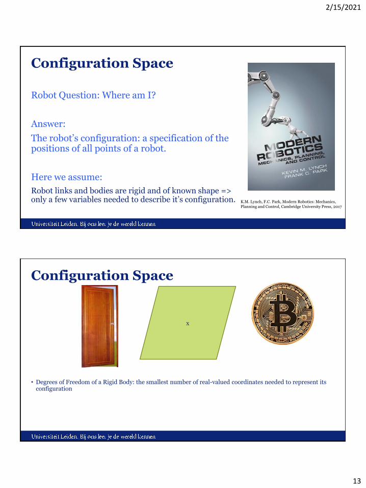
Configuration Space
Robot Question: Where am I?
Answer:
The robot’s configuration: a specification of the positions of all points of a robot.
Here we assume:
Robot links and bodies are rigid and of known shape => only a few variables needed to describe it’s configuration. K.M. Lynch, F.C. Park, Modern Robotics: Mechanics,
Planning and Control, Cambridge University Press, 2017
Configuration Space
• Degrees of Freedom of a Rigid Body: the smallest number of real-valued coordinates needed to represent its configuration
x

2/15/2021
14
Configuration Space
Assume a coin (heads) with 3 points A, B, C on it.
In the plane A,B,C have 6 degrees of freedom: (xA,yA) , (xB,yB) , (xC,yC)
A coin is rigid => 3 extra constraints on distances: dAB, dAC, dBC
These are fixed, wherever the location of the coin.
1. The coin and hence A can be placed everywhere => (xA,yA) free to choose.
2. B can only be placed under the constraint that its distance to A would be equal to dAB.
=> freedom to turn the coin around A with angle ϕAB => (xA, yA, ϕAB ) are free to choose.
3. C should be placed at distance dAC, dBC from A and B, respectively
=> only 1 possibility, hence no degree of freedom added.
Degrees of Freedom (DOF) of a Coin
= sum of freedoms of the points – number of independent constraints
= number of variables – number of independent equations = 6 – 3 = 3
Configuration Space
[1] Definition 2.1.
The configuration of a robot is a complete specification of the position of every point of the robot.
The minimum number n of real-valued coordinates needed to represent the configuration is the number of degrees of freedom (dof) of the robot.
The n-dimensional space containing all possible configurations of the robot is called the Configuration Space (C-space).
The configuration of a robot is represented by a point in its C-space.
Closed-chain robot: Stewart-Gough platform. [1]
Open-chain robot: Manipulator (in V-REP). [1]
2/15/2021
15
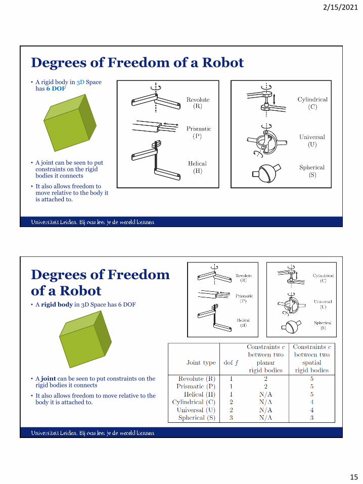
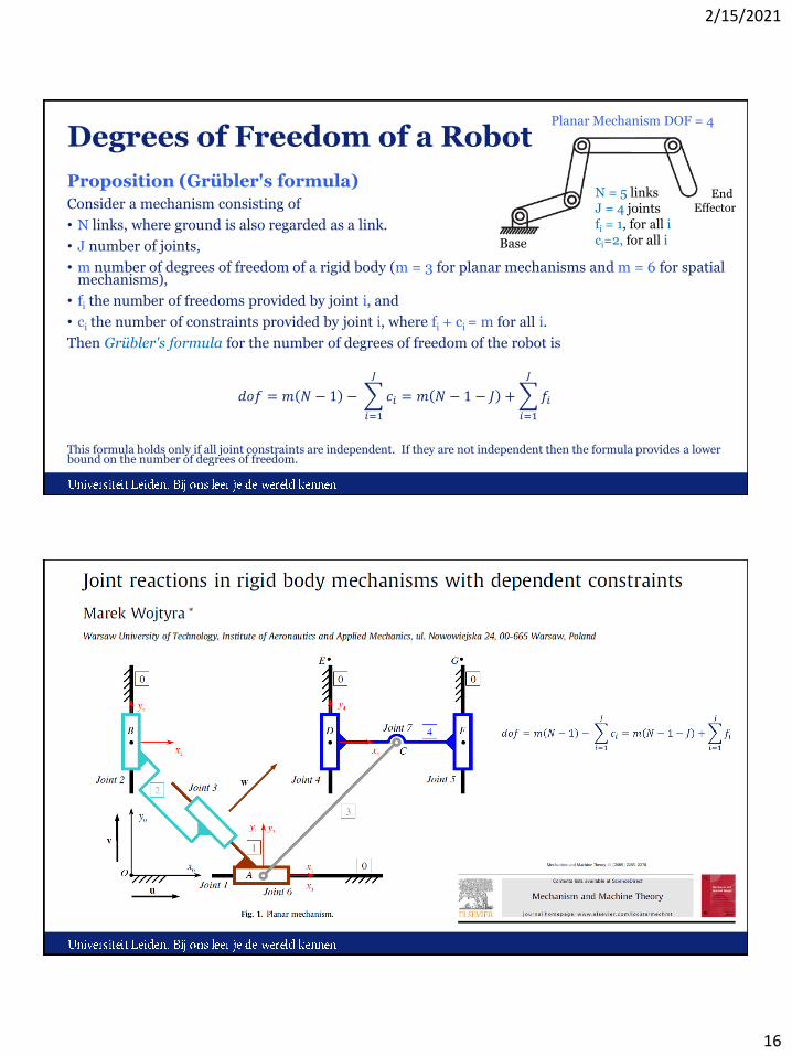
Degrees of Freedom of a Robot
• A rigid body in 3D Space has 6 DOF
• A joint can be seen to put constraints on the rigid bodies it connects
• It also allows freedom to move relative to the body it is attached to.
Degrees of Freedom of a Robot• A rigid body in 3D Space has 6 DOF
• A joint can be seen to put constraints on the rigid bodies it connects
• It also allows freedom to move relative to the body it is attached to.
2/15/2021
16
Degrees of Freedom of a Robot
Proposition (Grübler's formula)
Consider a mechanism consisting of
• N links, where ground is also regarded as a link.
• J number of joints,
• m number of degrees of freedom of a rigid body (m = 3 for planar mechanisms and m = 6 for spatialmechanisms),
• fi the number of freedoms provided by joint i, and
• ci the number of constraints provided by joint i, where fi + ci = m for all i.
Then Grübler's formula for the number of degrees of freedom of the robot is
𝑑𝑜𝑓 = 𝑚 𝑁 − 1 −
𝑖=1
𝐽
𝑐𝑖 = 𝑚 𝑁 − 1 − 𝐽 +
𝑖=1
𝐽
𝑓𝑖
This formula holds only if all joint constraints are independent. If they are not independent then the formula provides a lower bound on the number of degrees of freedom.
N = 5 linksJ = 4 jointsfi = 1, for all ici=2, for all i
Planar Mechanism DOF = 4
Base
End Effector

2/15/2021
17
• Links: 1 + 3 + 3 + 6 + 3 + 1 = 17• Joints: 21: 9x R(1 dof) and 12 x S(3 dof)• m= 6
Links1
3
3
6
3
1
stationary
mobile
Systems and their
Topologies
Note: S1 x S1 = T2 (not S2)
Coordinates
Explicit Coordinates• Euclidean (x,y)• Polar (r,ϕ)• Combined (x,y) x (r, ϕ)
Implicit Coordinates• { (x,y,z) | x2+y2+z2=1 }
2/15/2021
18
C-Space (Configuration Space)
How to describe a rigid body’s position and orientation in C-Space?
Fixed reference frame {s}
Reference fame attached to body {b}
In ℝ3 described by a 4x4 matrix with 10 constraints
(constraints, e.g.: unit-length, orthogonal)
Note: a point in ℝ3xS2xS1
Matrix can be used to:
1. Translate or rotate a vector or a frame
2. Change the representation of a vector or a frame
- for example from relative to {s} to relative to {b}
in the plane ℝ2xS1
C-Spaces
2/15/2021
19
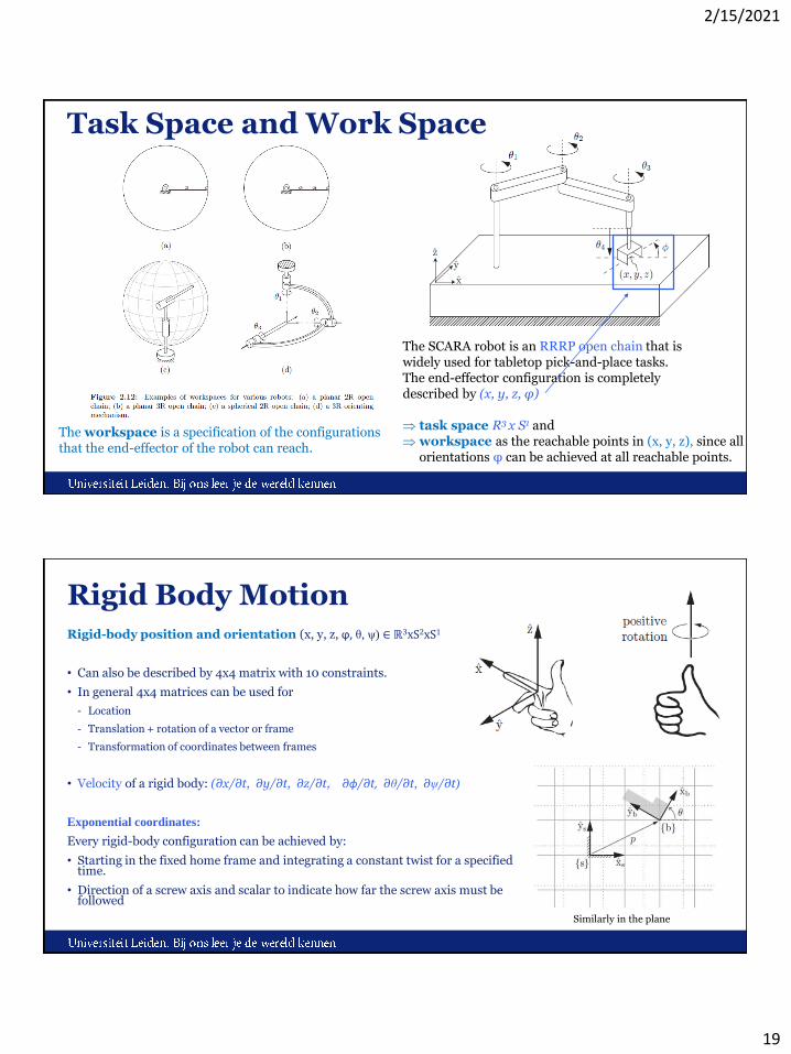
Task Space and Work Space
The SCARA robot is an RRRP open chain that iswidely used for tabletop pick-and-place tasks. The end-effector configuration is completely described by (x, y, z, φ)
task space R3 x S1 and workspace as the reachable points in (x, y, z), since all
orientations φ can be achieved at all reachable points.
The workspace is a specification of the configurations that the end-effector of the robot can reach.
Rigid Body MotionRigid-body position and orientation (x, y, z, ϕ, θ, ψ) ∈ ℝ3xS2xS1
• Can also be described by 4x4 matrix with 10 constraints.
• In general 4x4 matrices can be used for
- Location
- Translation + rotation of a vector or frame
- Transformation of coordinates between frames
• Velocity of a rigid body: (∂x/∂t, ∂y/∂t, ∂z/∂t, ∂ϕ/∂t, ∂θ/∂t, ∂ψ/∂t)
Exponential coordinates:
Every rigid-body configuration can be achieved by:
• Starting in the fixed home frame and integrating a constant twist for a specified time.
• Direction of a screw axis and scalar to indicate how far the screw axis must be followed
Similarly in the plane

2/15/2021
20
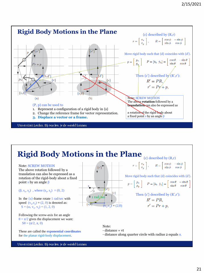
Rigid Body Motions in the Plane
Body
Fixed reference frame
Rigid Body Motions in the Plane{b} relative to {s}
{c} relative to {b}
Previously:
{c} relative to {s}
Note and verify: R = PQ, and r = Pq+p
2/15/2021
21
Rigid Body Motions in the Plane{c} described by (R,r)
Move rigid body such that {d} coincides with {d’}.
(P, p) can be used to1. Represent a configuration of a rigid body in {s}2. Change the reference frame for vector representation.3. Displace a vector or a frame.
Note: SCREW MOTIONThe above rotation followed by a translation can also be expressed as
a rotation of the rigid-body about a fixed point s by an angle β
Then {c’} described by (R’,r’):
Rigid Body Motions in the Plane{c} described by (R,r)
Move rigid body such that {d} coincides with {d’}.
Note: SCREW MOTIONThe above rotation followed by a translation can also be expressed as a rotation of the rigid-body about a fixed point s by an angle β
(β, sx, sy) , where (sx, sy) = (0, 2)
In the {s}-frame rotate 1 rad/sec with
speed (vx,vy) = (2, 0) is denoted as:
S = (ω, vx, vy) = (1, 2, 0)
Following the screw-axis for an angle
θ = π/2 gives the displacement we want:
Sθ = (π/2, π, 0)
These are called the exponential coordinates
for the planar rigid-body displacement.
Then {c’} described by (R’,r’):
(vx,vy) = (2,0)
1 rad/sec
Note: - distance = vt- distance along quarter circle with radius 2 equals π.

2/15/2021
22
Forward KinematicsThe forward kinematics of 3R Planar Open Chain can be written as a product of four homogeneous transformation matrices: T04 = T01T12T23T34, where
Home position M:
Forward Kinematics: Product of Exponentials
PoE parameters also known asEuler-Rodrigues parameters.
There are many other representations:- for example Denavit-Hartenberg
(1955) representation is very popular, but can be cumbersome
In velocity kinematics Jacobians are used.
2/15/2021
23
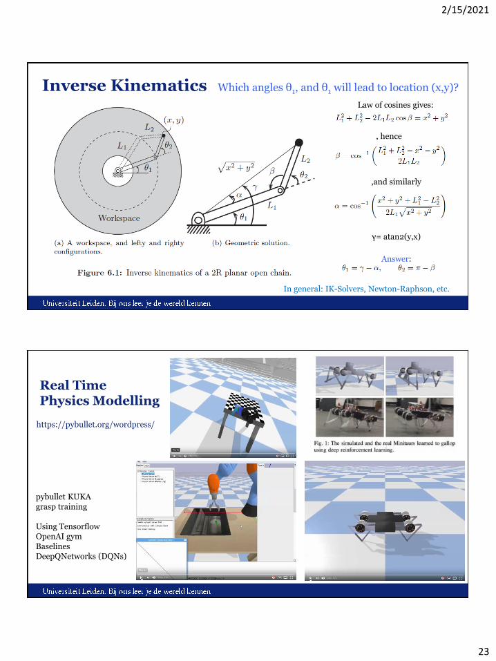
Inverse Kinematics Which angles θ1, and θ1 will lead to location (x,y)?
, hence
,and similarly
γ= atan2(y,x)
Law of cosines gives:
Answer:
In general: IK-Solvers, Newton-Raphson, etc.
Real Time Physics Modelling
https://pybullet.org/wordpress/
pybullet KUKA grasp training
Using TensorflowOpenAI gymBaselines DeepQNetworks (DQNs)
2/15/2021
24
Organization and OverviewPeriod: February 1st – May 10th 2021Time: Tuesday 16.15 – 18.00Place: https://smart.newrow.com/#/room/qba-943Lecturer: Dr Erwin M. Bakker ( [email protected] )Assistant: Erqian Tang
NB Register on Brightspace
Schedule:
1-2 Introduction and Overview8-2 No Class (Dies)15-2 Locomotion and Inverse Kinematics22-2 Robotics Sensors and Image Processing1-3 Yetiborg Introduction + SLAM Workshop I8-3 Project Proposals (presentation by students)15-3 Robotics Vision22-3 Robotics Reinforcement Learning 29-3 Yetiborg Qualification +
Robotics Reinforcement Learning Workshop II5-4 No Class (Eastern)12-4 Project Progress (presentations by students)19-4 Yetiborg Challenge26-4 Project Team Meetings3-5 Project Team Meetings10-5 Online Project Demos
Website: http://liacs.leidenuniv.nl/~bakkerem2/robotics/
Grading (6 ECTS):• Presentations and Robotics Project (60% of grade).• Class discussions, attendance, workshops and
assignments (40% of grade).• It is necessary to be at every class and to complete every
workshop.
Robotics Homework II
Visit http://modernrobotics.org and obtain the pdf of the book.
Read Chapters 1 and 2 and answer the following exercises:
• 2.2
• 2.10 for Figures 2.19 a, and b
• 2.19
Due: Monday 22-2 at 14.00 PM.
Email your answers to [email protected] with subject ‘Robotics2021 HW2’.

2/15/2021
25
References1. K.M. Lynch, F.C. Park, Modern Robotics: Mechanics, Planning and Control, Cambridge
University Press, 2017. ( DOI: 10.1017/9781316661239 )2. https://pybullet.org/wordpress/