robotics kinematics and dynamics · robot kinematics and dynamics_sivakumar_c. open chain...
TRANSCRIPT
Robotics kinematics and Dynamics
C. SivakumarAssistant Professor
Department of Mechanical EngineeringBSA Crescent Institute of Science and Technology
1Robot Kinematics and
Dynamics_Sivakumar_C

Robot kinematics• KINEMATICS – the analytical study of the
geometry of motion of a mechanism:– with respect to a fixed reference co-ordinate system,
– without regard to the forces or moments that causethe motion.
• In order to control and programme a robot wemust have knowledge of both its spatialarrangement and a means of reference to theenvironment.
2Robot Kinematics and
Dynamics_Sivakumar_C
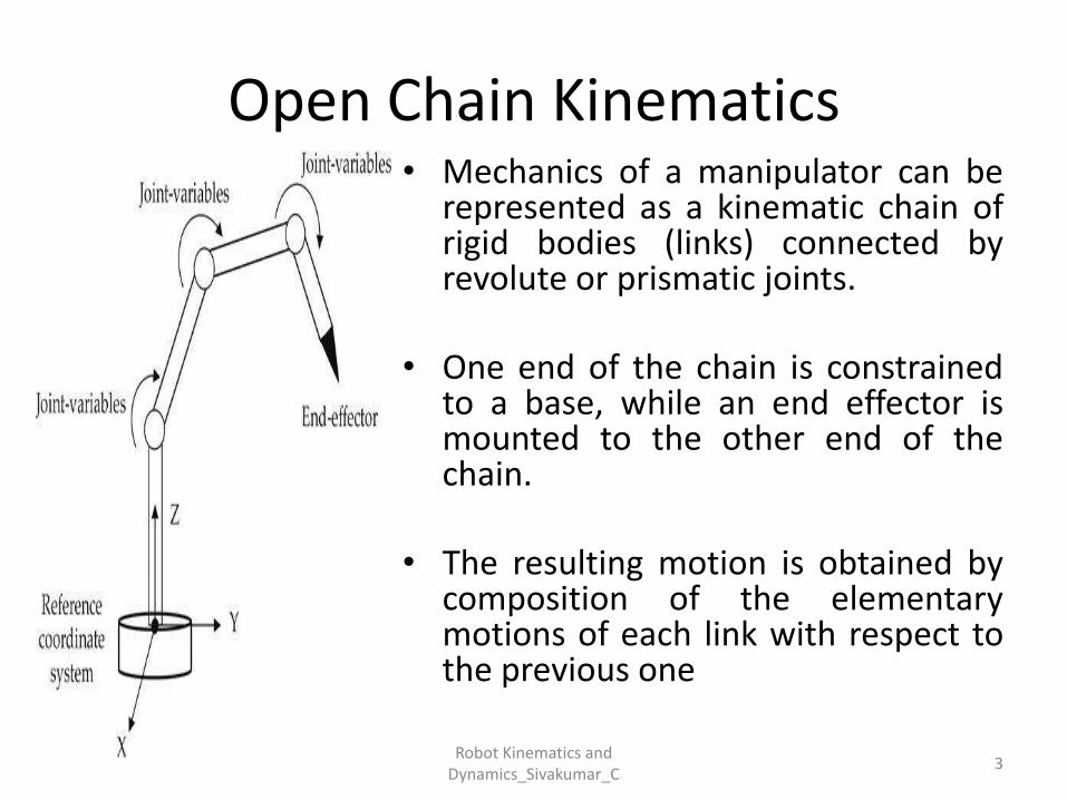
Open Chain Kinematics• Mechanics of a manipulator can be
represented as a kinematic chain ofrigid bodies (links) connected byrevolute or prismatic joints.
• One end of the chain is constrainedto a base, while an end effector ismounted to the other end of thechain.
• The resulting motion is obtained bycomposition of the elementarymotions of each link with respect tothe previous one
3Robot Kinematics and
Dynamics_Sivakumar_C
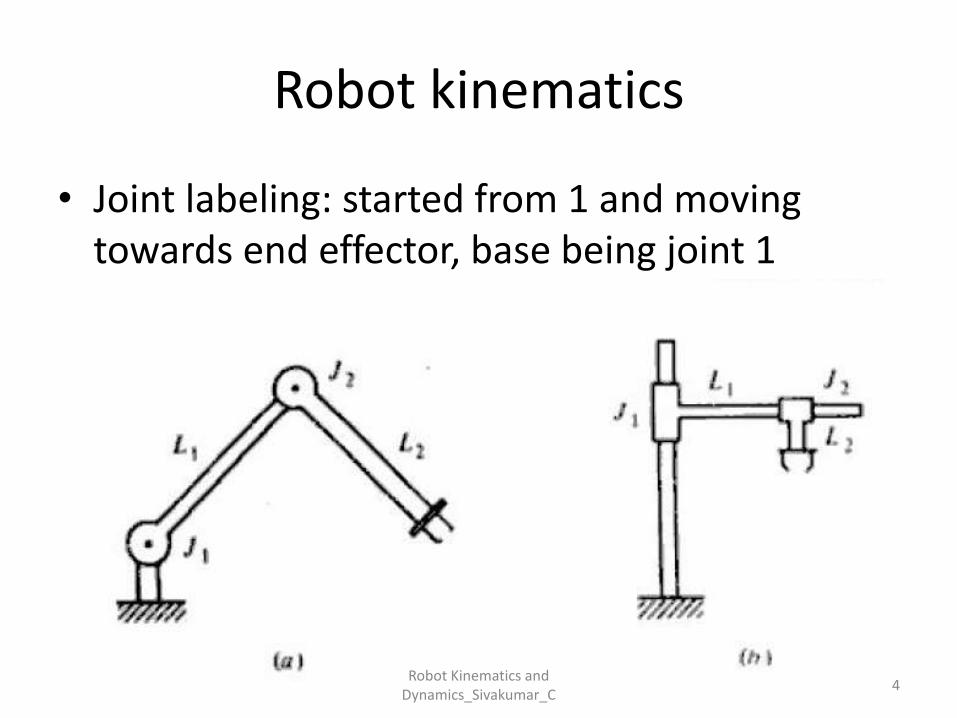
Robot kinematics
• Joint labeling: started from 1 and moving towards end effector, base being joint 1
4Robot Kinematics and
Dynamics_Sivakumar_C
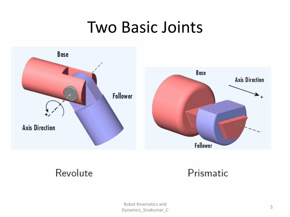
Two Basic Joints
5Robot Kinematics and
Dynamics_Sivakumar_C
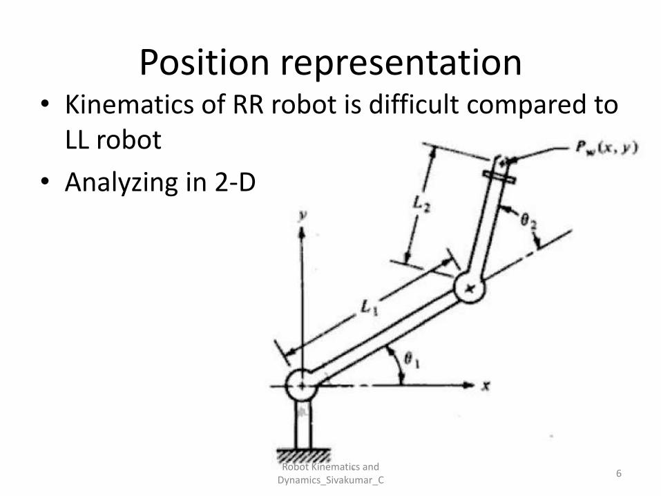
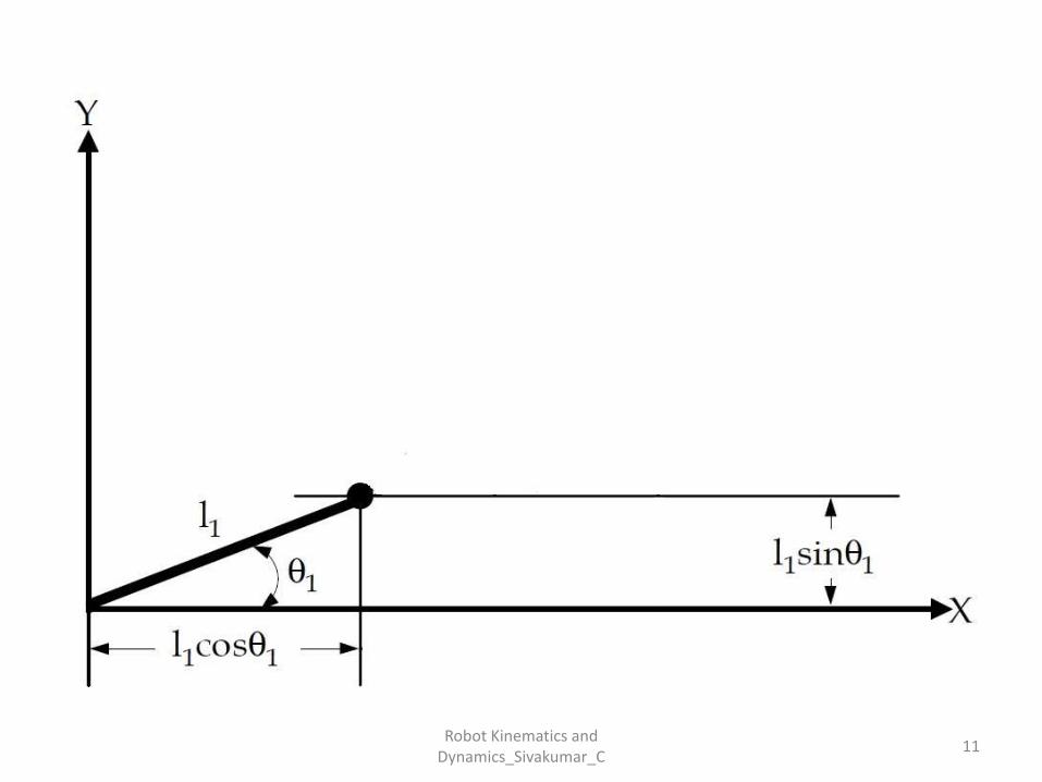
Position representation• Kinematics of RR robot is difficult compared to
LL robot
• Analyzing in 2-D
6Robot Kinematics and
Dynamics_Sivakumar_C
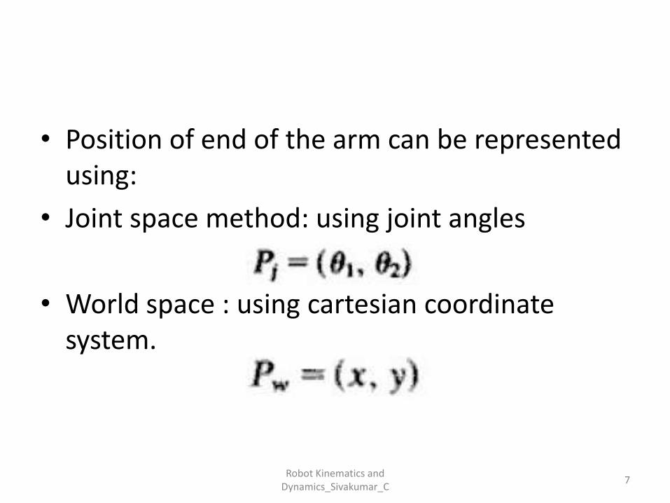
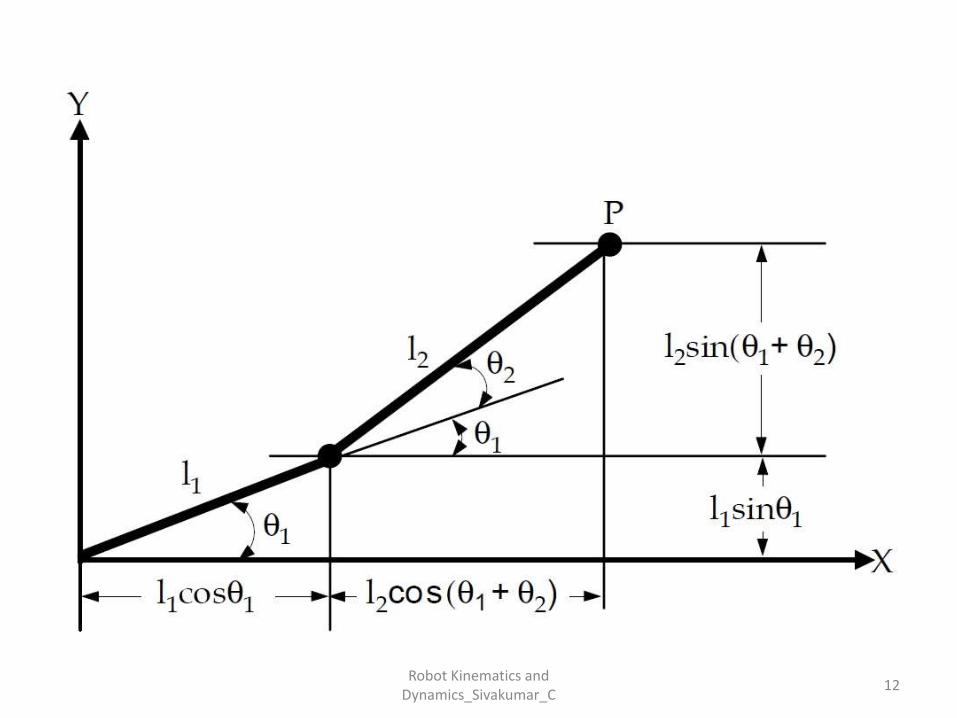
• Position of end of the arm can be represented using:
• Joint space method: using joint angles
• World space : using cartesian coordinate system.
7Robot Kinematics and
Dynamics_Sivakumar_C

• Transformation from one representation to other is necessary for many application.
Type of transformation:
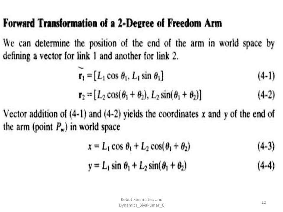
• Forward transformation or forward kinematics – going from joint space to world space
• Reverse transformation or inverse kinematics – going from world space to joint space.
8Robot Kinematics and
Dynamics_Sivakumar_C
• Direct (also forward) kinematics – Given arejoint relations (rotations, translations) for therobot arm. Task: What is the orientation andposition of the end effector?
• Inverse kinematics – Given is desired endeffector position and orientation. Task: Whatare the joint rotations and orientations toachieve this?
9Robot Kinematics and
Dynamics_Sivakumar_C
10Robot Kinematics and
Dynamics_Sivakumar_C
11Robot Kinematics and
Dynamics_Sivakumar_C
12Robot Kinematics and
Dynamics_Sivakumar_C
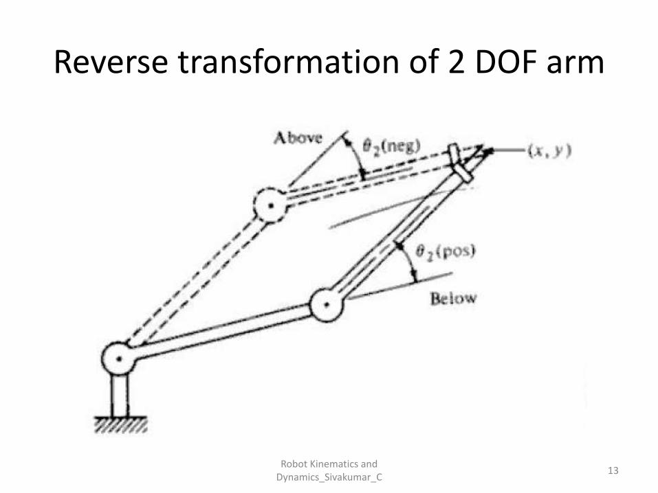
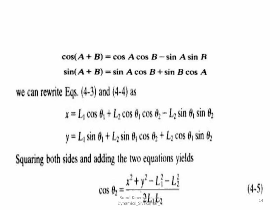
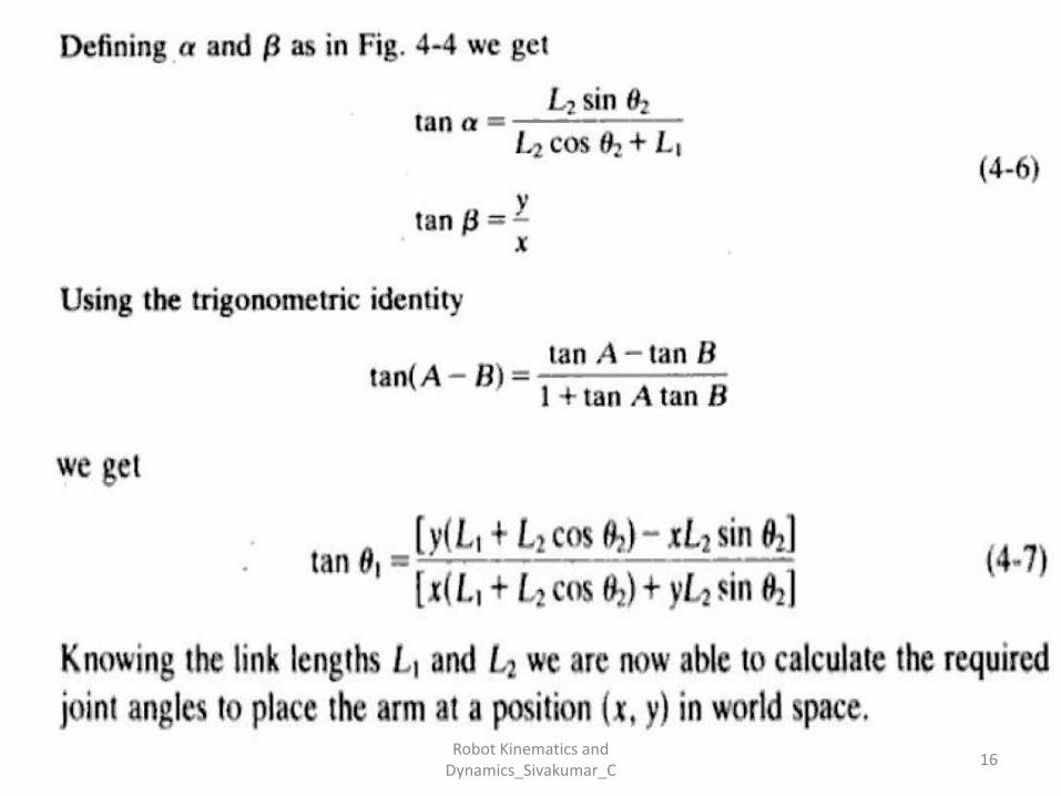
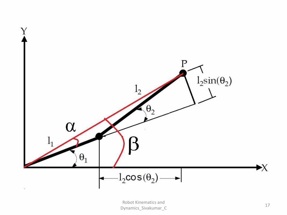
Reverse transformation of 2 DOF arm
13Robot Kinematics and
Dynamics_Sivakumar_C
14Robot Kinematics and
Dynamics_Sivakumar_C
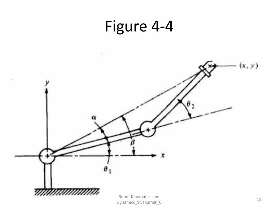
Figure 4-4
15Robot Kinematics and
Dynamics_Sivakumar_C
16Robot Kinematics and
Dynamics_Sivakumar_C
17Robot Kinematics and
Dynamics_Sivakumar_C
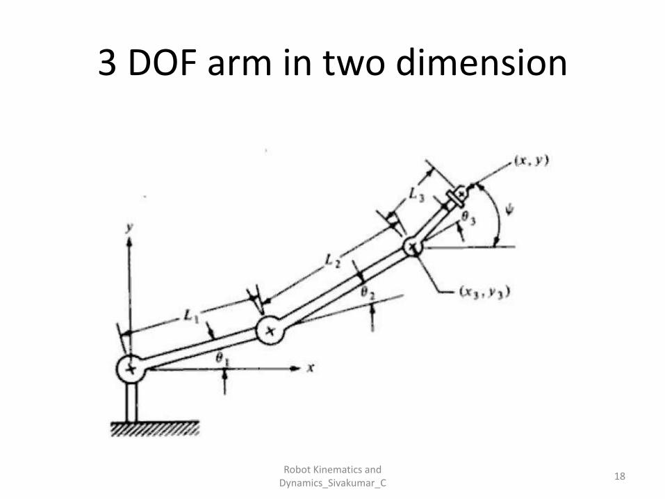
3 DOF arm in two dimension
18Robot Kinematics and
Dynamics_Sivakumar_C
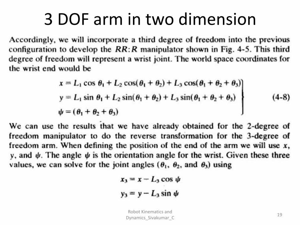
3 DOF arm in two dimension
19Robot Kinematics and
Dynamics_Sivakumar_C
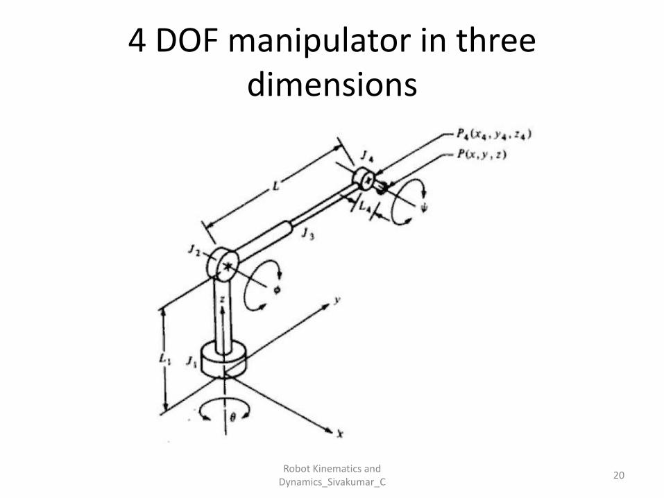
4 DOF manipulator in three dimensions
20Robot Kinematics and
Dynamics_Sivakumar_C
21Robot Kinematics and
Dynamics_Sivakumar_C
22Robot Kinematics and
Dynamics_Sivakumar_C
Robot Dynamics
• Accurate control of manipulator depends on precise control of joints
• Control of joints depends on forces and intertias acting on them
23Robot Kinematics and
Dynamics_Sivakumar_C
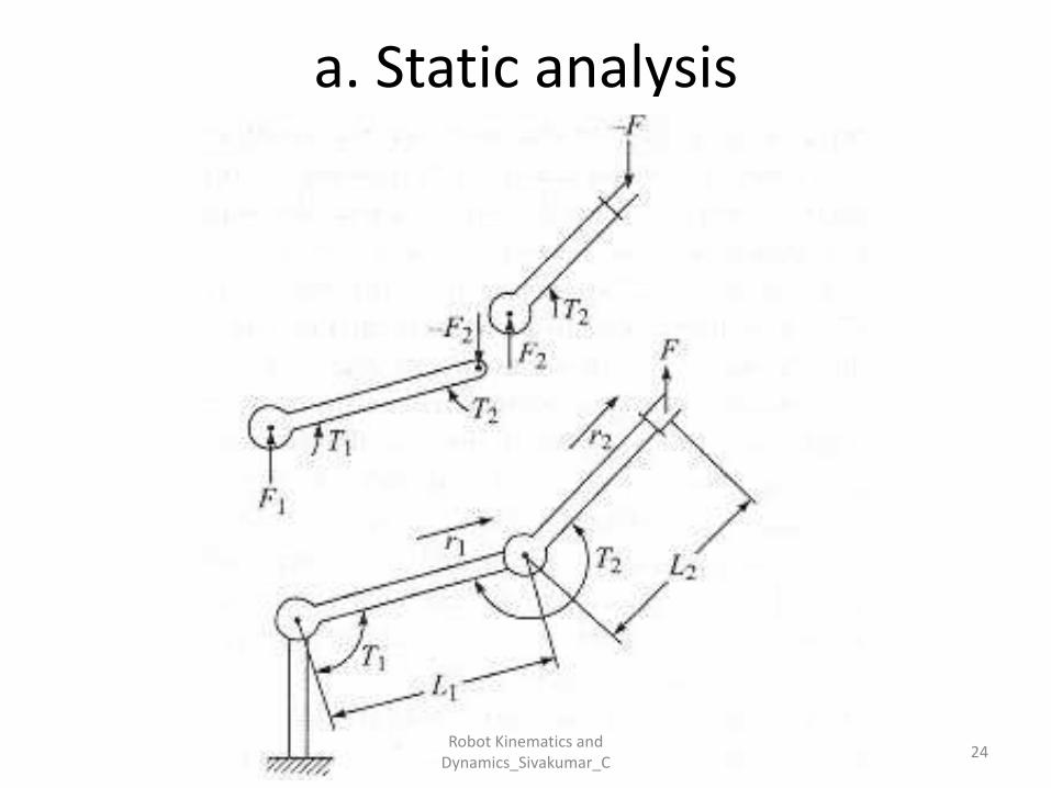
a. Static analysis
24Robot Kinematics and
Dynamics_Sivakumar_C
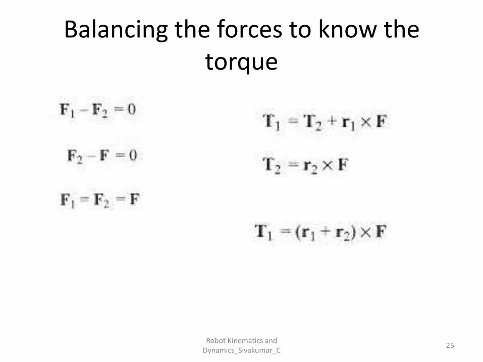
Balancing the forces to know the torque
25Robot Kinematics and
Dynamics_Sivakumar_C
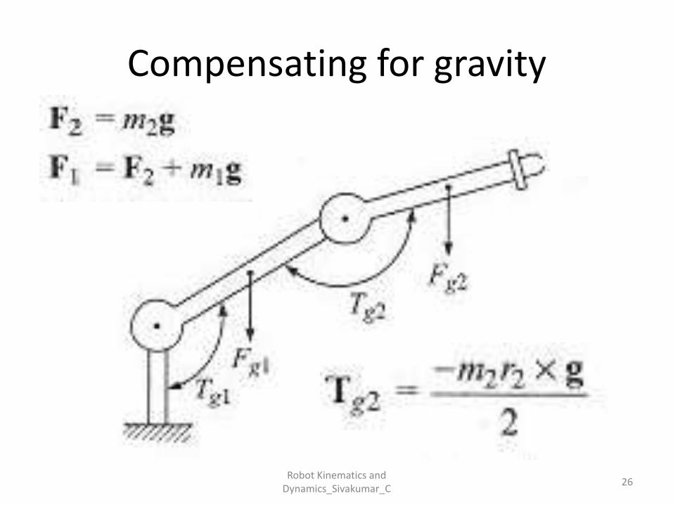
Compensating for gravity
26Robot Kinematics and
Dynamics_Sivakumar_C

Robot arm dynamics
27Robot Kinematics and
Dynamics_Sivakumar_C
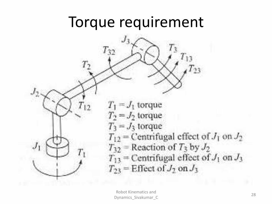
Torque requirement
28Robot Kinematics and
Dynamics_Sivakumar_C
Kinematic• Forward (direct) Kinematics
• Given: The values of the joint variables.
• Required: The position and the orientation of the end effector.
• Inverse Kinematics
• Given : The position and the orientation of the end effector.
• Required : The values of the joint variables.
29Robot Kinematics and
Dynamics_Sivakumar_C
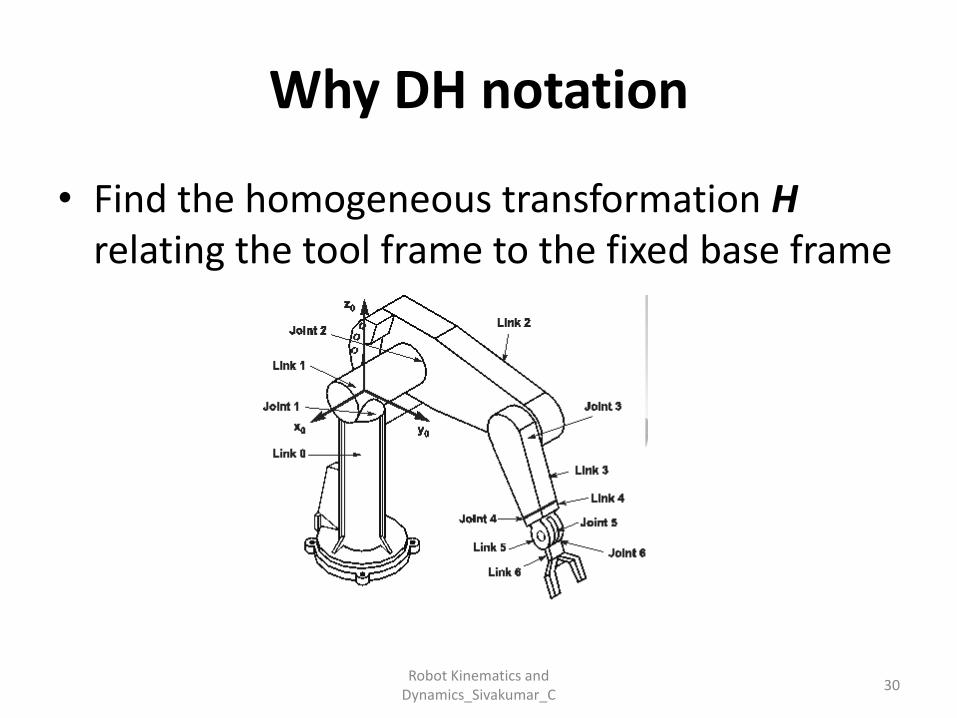
Why DH notation
• Find the homogeneous transformation Hrelating the tool frame to the fixed base frame
30Robot Kinematics and
Dynamics_Sivakumar_C
Why DH notation
• A very simple way of modeling robot links and joints that can be used for any kind of robot configuration.
• This technique has became the standard way of representing robots and modeling their motions.
31Robot Kinematics and
Dynamics_Sivakumar_C
DH Techniques
1. Assign a reference frame to each joint (x-axis and z-axis). The D-H representation does not use the y-axis at all.
2. Each homogeneous transformation Ai is represented as a product of four basic transformations
32Robot Kinematics and
Dynamics_Sivakumar_C
DH Techniques
33
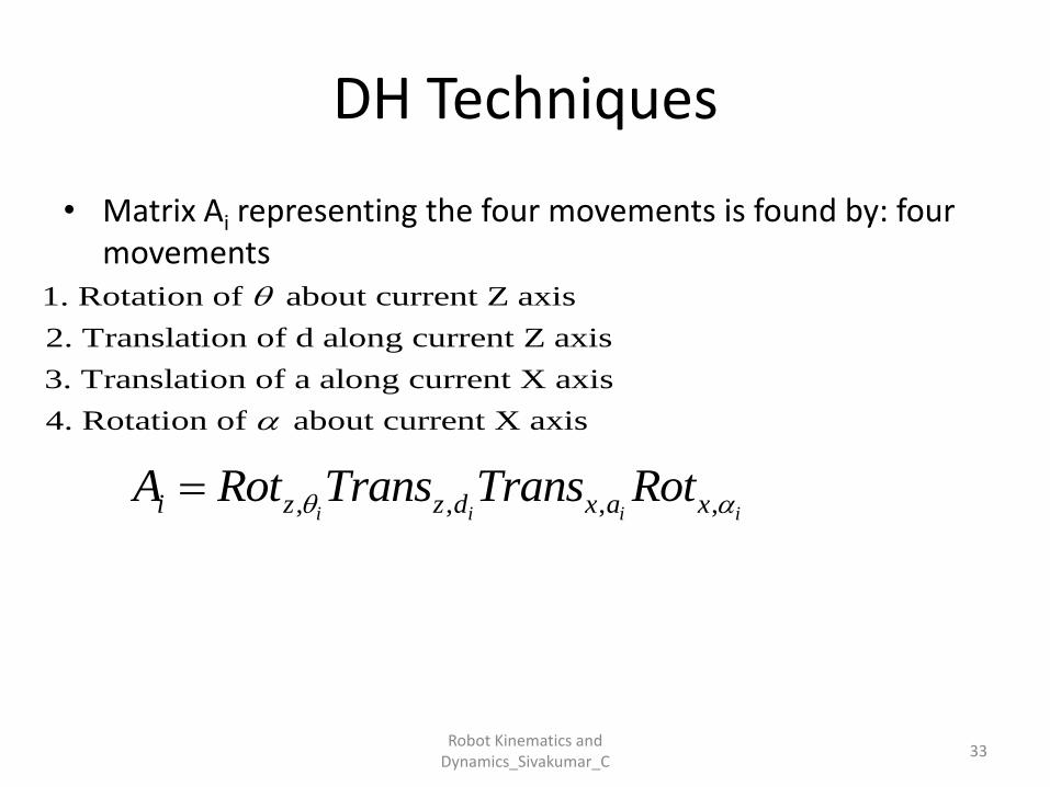
• Matrix Ai representing the four movements is found by: four movements
, , , ,i i i ii z z d x a xA Rot Trans Trans Rot
1. Rotation of about current Z axis
2. Translation of d along current Z axis
3. Translation of a along current X axis
4. Rotation of about current X axis
Robot Kinematics and Dynamics_Sivakumar_C
34
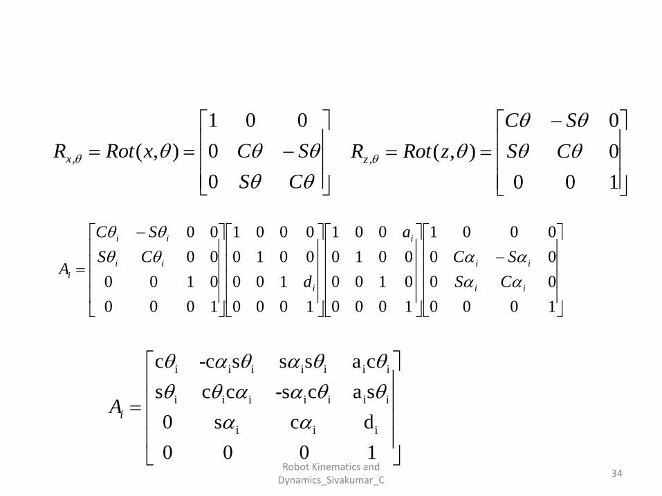
i i i i i i i
i i i i i i i
i i i
c -c s s s a c
s c c -s c a s
0 s c d
0 0 0 1
iA
CS
SCxRotRx
0
0
001
),(,
100
0
0
),( ,
CS
SC
zRotRz
1000
00
00
0001
1000
0100
0010
001
1000
100
0010
0001
1000
0100
00
00
ii
ii
i
i
ii
ii
iCS
SC
a
d
CS
SC
A
Robot Kinematics and Dynamics_Sivakumar_C
DH Techniques
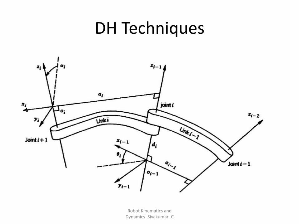
• The link and joint parameters :
• Link length ai : the offset distance between the Zi-1
and Zi axes along the Xi axis.
• Link offset di the distance from the origin of frame i−1 to the Xi axis along the Zi-1 axis.
35Robot Kinematics and
Dynamics_Sivakumar_C
DH Techniques
36
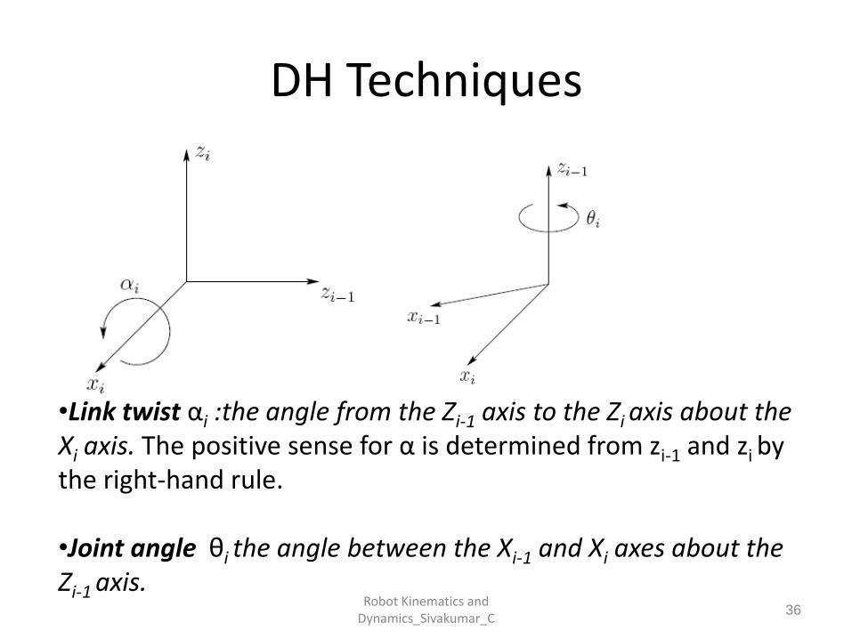
•Link twist αi :the angle from the Zi-1 axis to the Zi axis about the Xi axis. The positive sense for α is determined from zi-1 and zi by the right-hand rule.
•Joint angle θi the angle between the Xi-1 and Xi axes about the Zi-1 axis.
Robot Kinematics and Dynamics_Sivakumar_C
DH Techniques
• The four parameters:
ai: link length, αi: Link twist , di : Link offset and
θi : joint angle.
• The matrix Ai is a function of only a single variable qi , it turns out that three of the above four quantities are constant for a given link, while the fourth parameter is the joint variable.
37Robot Kinematics and
Dynamics_Sivakumar_C
DH Techniques
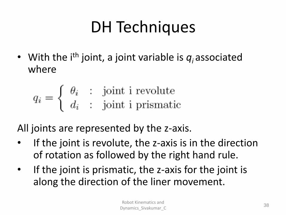
• With the ith joint, a joint variable is qi associated where
All joints are represented by the z-axis.
• If the joint is revolute, the z-axis is in the direction of rotation as followed by the right hand rule.
• If the joint is prismatic, the z-axis for the joint is along the direction of the liner movement.
38Robot Kinematics and
Dynamics_Sivakumar_C
DH Techniques
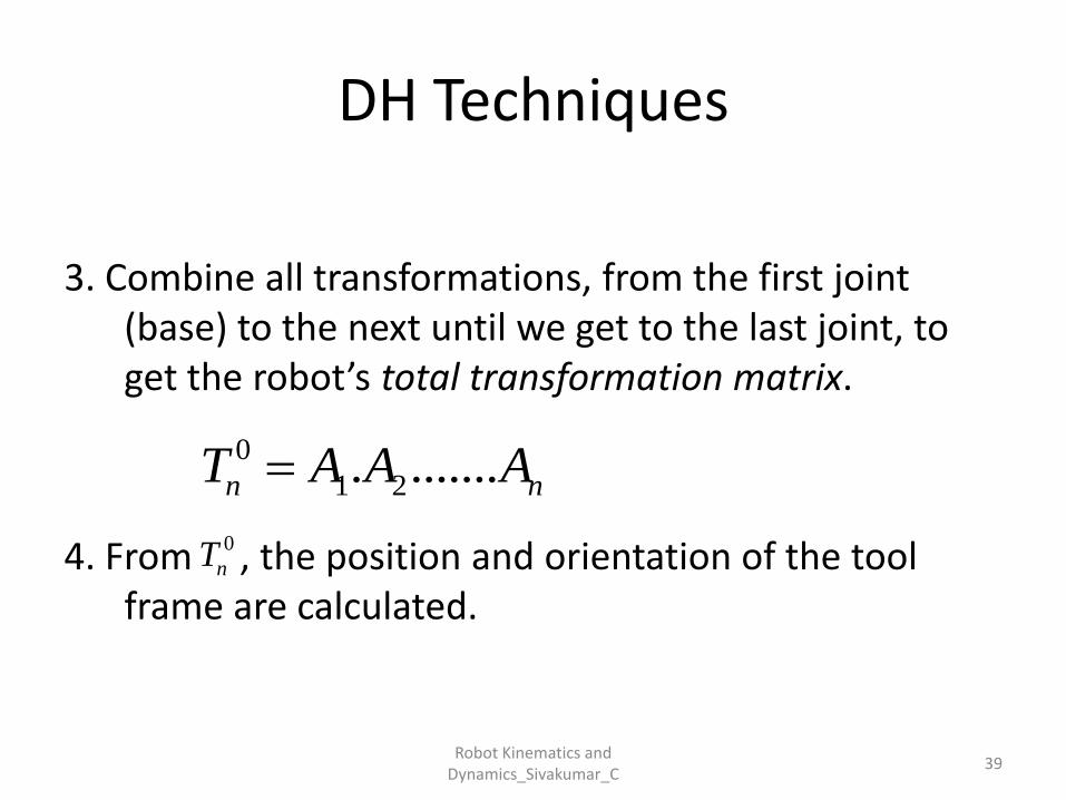
3. Combine all transformations, from the first joint (base) to the next until we get to the last joint, to get the robot’s total transformation matrix.
4. From , the position and orientation of the tool frame are calculated.
39
0
1 2. .......n nT A A A
0
nT
Robot Kinematics and Dynamics_Sivakumar_C
DH Techniques
40Robot Kinematics and
Dynamics_Sivakumar_C

DH Techniques
41Robot Kinematics and
Dynamics_Sivakumar_C
DH Techniques
42Robot Kinematics and
Dynamics_Sivakumar_C
DH Techniques
43
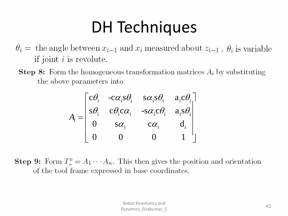
i i i i i i i
i i i i i i i
i i i
c -c s s s a c
s c c -s c a s
0 s c d
0 0 0 1
iA
Robot Kinematics and Dynamics_Sivakumar_C