robotic motors: key concepts actuators actuators.pdf · 2012-12-23 · motors: key concepts n s n s...
TRANSCRIPT

1
Robotic ACTUATORS
Based on the lecture note fromCS499 MECHATRONICS
at
Motors: Key Concepts
N S
N
S
Motors: Key Concepts
N SN S
Motors: Key Concepts
N SSN

2
Motors: Key Concepts
N S
+ -
SN
I
I
AC inverts the poles
AC Motor
The speed of the AC motor depends only on three variables:
1. The fixed number of winding sets (known as poles) built into the motor, which determines the motor's base speed.
2. The frequency of the AC line voltage.
3. The amount of torque loading on the motor, which causes slip.
Motor: Key Concepts
• In the simplest three-phase motor, there are 3 separate electromagnets formed by the single set of three-way windings.
• The windings are in the exterior (stator) section.
• The changing field in the windings causes the rotor to rotate around the axis of the motor.
Stepping Motors
Basic Speed:
As the three voltage phases (each 120 degrees off from one another) gradually rise and fall, the strength of each electromagnetic winding set rises and falls in relation to the frequency of the voltage changes.
This causes the rotor to rotate once per voltage cycle. In a 60 Hertz system, this results in a base speed of 60 Hertz, or 3600 rpm.

3
Stepping Motors
• To rotate the motor continuously, power must be applied to the 3 windings in sequence.
• The following control sequence will spin the motor clockwise for 2 revolutions: (1 means turning on the current through a motor winding).
Winding 1: 1001001001001001001001001 Winding 2: 0100100100100100100100100 Winding 3: 0010010010010010010010010 time --->
Stepping Motors
Stepper motors have more than 2 terminals, up to 6 and 8,
which activate sequentially each coil within the motor.
• The timing of the signal determines the motor’s speed.
• The phase between the signal determines the direction.
• The number of commands determines the position
• Stepping motors come in a wide range of angular resolutions.
• The coarsest motors typically turn 90 degrees per step, while high resolution permanent magnet motors are commonly able to handle 1.8 or even 0.72 degrees per step
Motors: Key Concepts
N S
+ -
SN
I
I
DC-AC Commutator
Brush-type DC Motors: Key Concepts
N S
+ -
S
N
CommutatorBrushes

4
Brush-type DC Motors: Key Concepts
N S
+ -
S
N
Brush-type DC Motors: Key Concepts
DC Motors: Basic Principle
Brush-like and Brushless DC Motors
Brush-like• To allow the rotor to turn without twisting the wires, the ends of the wire loop
are connected to a set of contacts called the commutator, which rubs against a set of conductors called the brushes.
• The brushes make electrical contact with the commutator as it spins, and are connected to the positive and negative leads of the power source, allowing electricity to flow through the loop.
• The electricity flowing through the loop creates a magnetic field that interacts with the magnetic field of the permanent magnet to make the loop spin.
Brushless:• DC current is converted into AC current, using position sensors and
microcontroller.
Elementary Theory of DC Permanent Magnet Motors
A motor transforms Electrical Energy into Mechanical Energy.
IVPe ⋅=
ω⋅= TPm
Electrical Power
Mechanical Power
me PP ⋅= η
5
Elementary Theory of DC Permanent Magnet Motors
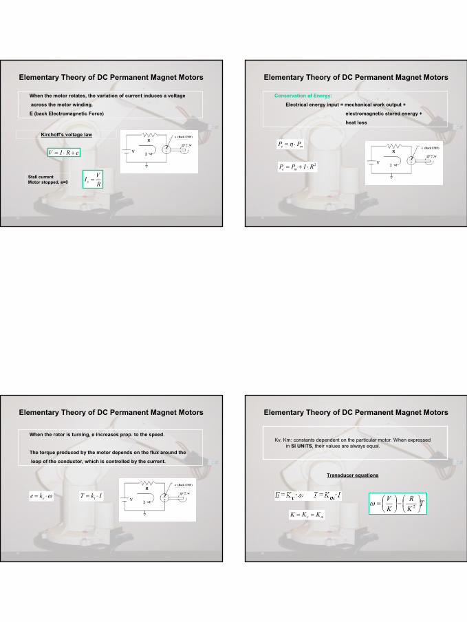
When the motor rotates, the variation of current induces a voltage
across the motor winding.
E (back Electromagnetic Force)
eRIV +⋅=
RVIs =Stall current
Motor stopped, e=0
e (Back EMF)Kirchoff's voltage law
Elementary Theory of DC Permanent Magnet Motors
Conservation of Energy:
Electrical energy input = mechanical work output +
electromagnetic stored energy +
heat loss
me PP ⋅= η
2RIPP me ⋅+=
e (Back EMF)
Elementary Theory of DC Permanent Magnet Motors
When the rotor is turning, e increases prop. to the speed.
The torque produced by the motor depends on the flux around the
loop of the conductor, which is controlled by the current.
IkT t ⋅=
e (Back EMF)
ω⋅= eke
Elementary Theory of DC Permanent Magnet Motors
Kv, Km: constants dependent on the particular motor. When expressed in SI UNITS, their values are always equal.
Transducer equations
TKR
KV
−
= 2ω
mKKK == ν

6
The speed is inversely proportional to the torque.
KV
o = ω
TKR
− = 2οωω
RKVT =
Elementary Theory of DC Permanent Magnet Motors
T
w No Load Condition
Stall Torque
The current is proportional to the torque.
The stall current is the maximal current that the motor can pump.
oI
RVIs =
RKVTs =
Elementary Theory of DC Permanent Magnet Motors
T
I
Stall Current
Stall Torque
The power output is the product of torque and speed.
Elementary Theory of DC Permanent Magnet Motors
TRVT
kRPm ⋅+⋅
− = 2
2
0 = ∂
∂tPm
The maximum power is reached at half the stall torque
sTRVk
T ⋅ = ⋅
⋅=
21
2
The point of maximum efficiency is a low torque, high-speed operating point.
Therefore, it is good to take an oversized motor so that it can run at the maximum of efficiency.
Elementary Theory of DC Permanent Magnet Motors
2
0max 1
−=
sIIη

7
Hydraulic and Pneumatic Motors
Air InletPiston rod
Double Acting Cylinder
Retracted
ExtendedAir Inlet
Stroke Extension limit
Mechanical Stops
Hydraulic and Pneumatic Motors
Pneumatic Power - Air-powered cylinders
• Compressed air
• Either stored on board or injected by a pump
• Produces linear motion through activation of cylinders
Hydraulic Power - Fluid (non-air)-powered cylinders
• Uncompressible fluid, most often oil.
• Requires a pump to generate the pressure and flow rate needed.
• Complex and difficult to build effectively, and costly.
Motors Properties: Comparison
Generally small. Cannot vary magnetic field strength.
Small, compact and easy to find. Very inexpensive.
DC permanent magnet motors
Require more current than permanent magnet motors, since field coil must be energized. Generally heavier than permanent magnet motors. More difficult to obtain.
Wide range of speeds and torques. More powerful than permanent magnet motors.
DC Motors with field coil.Robota motors
Expensive and hard to find. Require a switching control circuit.
Very precise speed and position control. High torque at low speed.
Stepper Motors
DisadvantagesAdvantagesType
Motors Properties: Comparison
8
• Maxon A-max 26 mm• Rhombic moving coil design provides long life, low electrical noise, fast
acceleration and high efficiency. • The ironless rotor allows zero cogging and simple accurate control. Available
with either precious metal brushes or graphite brushes the power rating ranges from 4 to 11 watts.
• The motor length is 44.7 mm (1.76 in) and weighs in at 106 g (3.73 oz). • Maximum efficiency: 86%. • Maximum continuous torque from the motor alone is up to 15.5 mNm (2.19 oz-
in)• Matching gearheads available with ratios ranging from 4.3:1 to 2548:1 capable
of delivering 4500 mNm (637 oz-in) of continuous torque.• Matching encoders are also available.
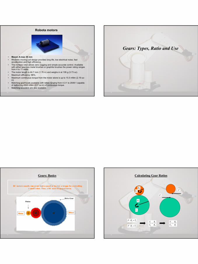
Robota motors
Gears: Types, Ratio and Use
Gears: Basics
Motor Wheel
DC motors usually run at too high a speed or too low a torque for controlling a small robot. Thus, a DC must be geared down.
Pinion
Drive Gear
Calculating Gear Ratios
0
1
0
1
RR
TT
=1
0
0
1
RR
VV
=
0R
1R
1V
0V
0TRF o =⋅
11 TRF =⋅
F
F

9
Calculating Gears Ratios for a Gear Train
Gear Train: ratio 1:60
2
0
2
RR
TT
=
2
0
0
2
RR
VV
= 02 61 VV ⋅=
02 6 TT ⋅=
0R
1R
2R
Motor Wheel
Increase torque
Decrease speed
Gears: Types and Descriptions
Straight Gears
WormGears
Bevel GearsHelical Gears
Spur Gears
Motors Interfacing and PID controllers
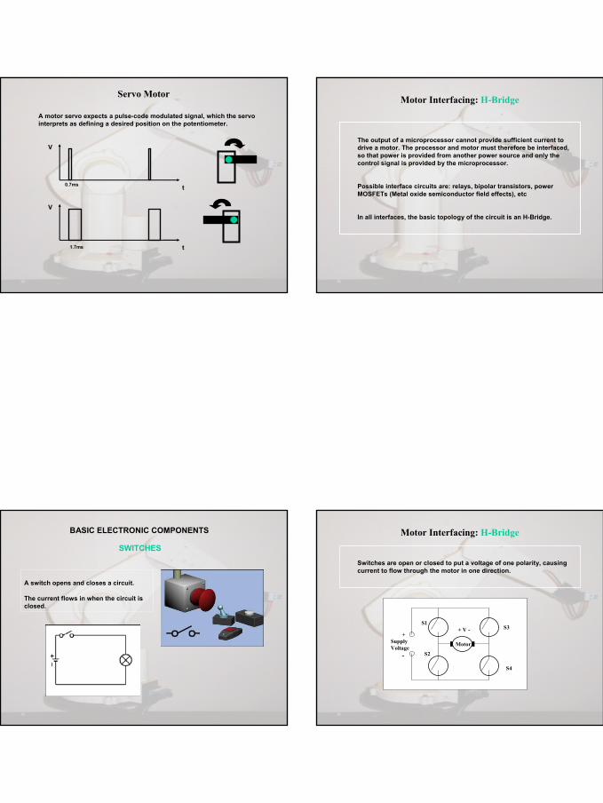
Servo Motor
A servo motor is provided with a controller which continuously adjusts the electrical current to the motor in order to reach a set-point position.
It is provided with 3-wires:
1. power,
2. ground,
3. control input with pulse-width signal to determine the position the motor should servo.
The motor elements consist of a:
• DC motor
• gear train
• limit stops beyond which the shaft cannot turn
• a potentiometer for position feedback
• an integrated circuit for position control
10
Servo Motor
A motor servo expects a pulse-code modulated signal, which the servo interprets as defining a desired position on the potentiometer.
t
V
0.7ms
t
V
1.7ms
Motor Interfacing: H-Bridge
The output of a microprocessor cannot provide sufficient current to drive a motor. The processor and motor must therefore be interfaced, so that power is provided from another power source and only thecontrol signal is provided by the microprocessor.
Possible interface circuits are: relays, bipolar transistors, power MOSFETs (Metal oxide semiconductor field effects), etc
In all interfaces, the basic topology of the circuit is an H-Bridge.
BASIC ELECTRONIC COMPONENTS
SWITCHES
A switch opens and closes a circuit.
The current flows in when the circuit is closed.
Motor Interfacing: H-Bridge
S1
S2
+Supply Voltage
-
S3
S4
Motor
+ V -
Switches are open or closed to put a voltage of one polarity, causing current to flow through the motor in one direction.

11
Motor Interfacing: H-Bridge
S1
S2
+Supply Voltage
-
S3
S4
Motor
+ V -
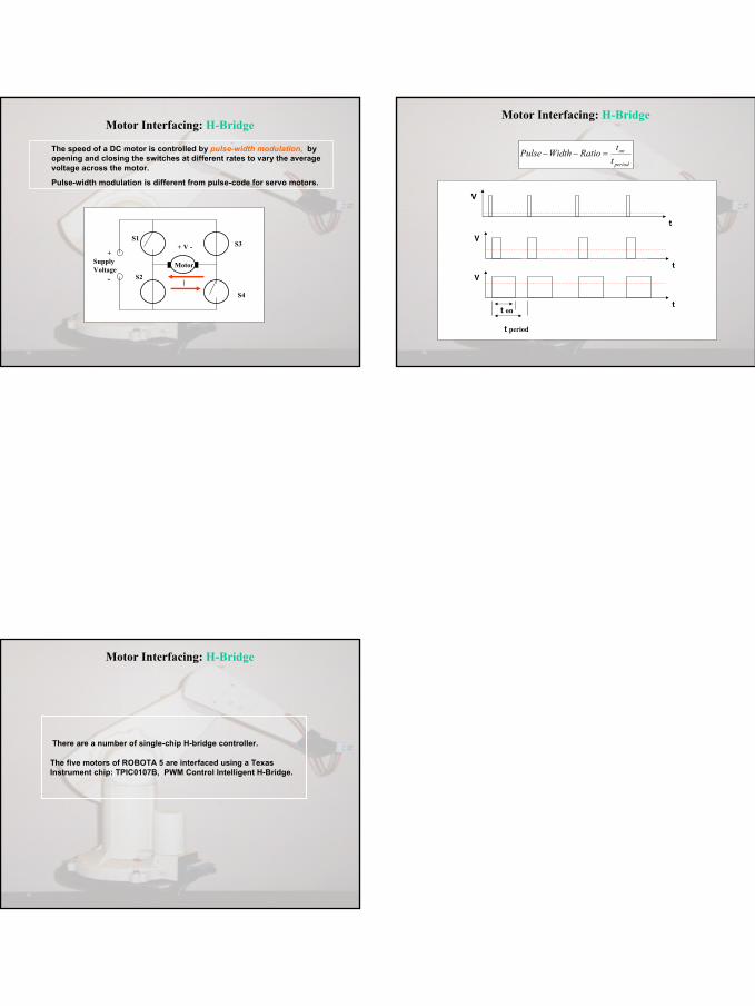
S1, S4 Closed and S2, S3 Open: current flows from left to right
I
Motor Interfacing: H-Bridge
S1
S2
+Supply Voltage
-
S3
S4
Motor
+ V -
S1, S4 Open and S2, S3 Closed: current flows from right to left
I
Motor Interfacing: H-Bridge
S4
Motor Interfacing: H-Bridge
S4
12
Motor Interfacing: H-Bridge
S1
S2
+Supply Voltage
-
S3
S4
Motor
+ V -
I
The speed of a DC motor is controlled by pulse-width modulation, by opening and closing the switches at different rates to vary the average voltage across the motor.
Pulse-width modulation is different from pulse-code for servo motors.
Motor Interfacing: H-Bridge
t
V
t
V
t
V
t on
t period
period
on
ttRatioWidthPulse =−−
Motor Interfacing: H-Bridge
There are a number of single-chip H-bridge controller.
The five motors of ROBOTA 5 are interfaced using a TexasInstrument chip: TPIC0107B, PWM Control Intelligent H-Bridge.