robot optimized for handling small motoman series...5.39 nxm 5.39 nxm 2.94 nxm 0.1 kgxm2 0.1 kgxm2...
TRANSCRIPT

Robots optimized for handling can also be used for assembly and other applications.
Small but MightySmall but Mighty
Robot Optimized for Handling
Small-MOTOMAN Series
Vertically Articulated Robot
(For Use with FS100 Controllers)
R009QMS Accreditation JQA-EM0924JQA-0813
Certified for
ISO9001 and
ISO14001
Compact
Realize the compact production
facilities of your dream
Wide selection of small
manipulators with payloads
ranging from 3 kg to 20 kg
Compact controller(470 W × 420 D × 200 H) for
control of 8 axes
Expandable (Optional)
Enable user to develop their
own application programs.
Environment for users to develop
their own application programs.
Users can develop application
control programs using C language.
High speedIncrease productivityHigh-speed motions with a wide
motion rangeReduced cycle times by using the
controller with a high-speed control
cycle and a function to suppress
vibrations in the robot’s hand.
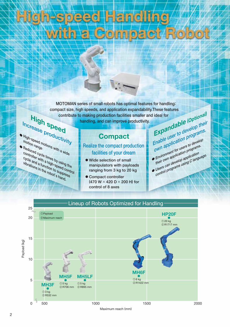
Lineup of Robots Optimized for Handling
5
10
15
20
25
0
Payload
Maximum reach
Maximum reach (mm)
MH3F
1
2
MH5F
1 3 kg
R532 mm2
1 5 kg
R706 mm2
MH5LF
1 5 kg
R895 mm2
MH6F
1 6 kg
R1422 mm2
HP20F
1 20 kg
R1717 mm2
500 1000 1500 2000
Paylo
ad
(kg
)
MOTOMAN series of small robots has optimal features for handling:
compact size, high speeds, and application expandability.These features
contribute to making production facilities smaller and ideal for
handling, and can improve productivity.
U
2

S M A L L - M O T O M A N S E R I E S
Manipulator Specifications
(turning)
(lower arm)
(upper arm)
(wrist roll)
(wrist pitch/yaw)
(wrist twist)
(turning)
(lower arm)
(upper arm)
(wrist roll)
(wrist pitch/yaw)
(wrist twist)
MOTOMAN-MH3F
YR-MH0003F-A00
6 (Vertically articulated)
3 kg
±0.03 mm
-160° - +160°-85° - +90°-105° - +260°-170° - +170°-120° - +120°-360° - +360°
3.49 rad/s, 200°/s2.62 rad/s, 150°/s3.32 rad/s, 190°/s5.24 rad/s, 300°/s5.24 rad/s, 300°/s7.33 rad/s, 420°/s
Allowable
Moment
Allowable
Inertia
(GD2/4)
Ambient
conditions
5.39 N m
5.39 N m
2.94 N m
0.1 kg m2
0.1 kg m2
0.03 kg m2
27 kg
0˚C to +40˚C
20 to 80%RH (non-condensing)
4.9 m/s2 or less
0.5 kVA
Free from corrosive gasses or liquids, or explosive gasses
Free from exposure to water, oil, or dust
Free from excessive electrical noise (plasma)
**
12
::Conforms to JIS B 8432. Varies in accordance with applications and motion patterns.
-axis
-axis
-axis
-axis
-axis
-axis
-axis
-axis
-axis
-axis
-axis
-axis
S
L
U
R
B
T
S
L
U
R
B
T
(wrist roll)
(wrist pitch/yaw)
(wrist twist)
(wrist roll)
(wrist pitch/yaw)
(wrist twist)
-axis
-axis
-axis
-axis
-axis
-axis
R
B
T
R
B
T
Temperature
Humidity
Vibration
Others
Range of
Motion
Maximum
Speed
Model
Type
Controlled Axis
Payload
Repeatability*1
Power Requirements*2
Mass
Note : SI units are used for specifications.
MOTOMAN-MH3F
Dimensions Units : mm : P-point Maximum Envelope
Payload: 3 kg
Maximum Reach: R532 mm
The MOTOMAN-MH3F, a compact manipulator with a motor of 80 W or
less mounted on all axes, requires minimal space (baseplate: 240 mm ×
170 mm). No fence is required for robot’s working area. The robot can
be used in applications such as automated guided vehicles (AGVs),
testing equipment, and educational tools.
Standard models include four air hoses (diameter: 4 mm), and an
internal user I/O wiring harness (0.2 mm2 × 10) running through the
U-arm. This structure simplifies wiring and tubing for easier system
construction.
Floor-mounted, wall-mounted, and ceiling-mounted types are available.
(Note 2)(Note 1)
P-Point
193
47
38
1
133
74
38
9
33
7
57
55°
532
583
822
90
0
270
188229372
79
30
531 40
189
180
21
21
9
15
82
040
85°
260°
27
6
65
9
42
0
29
02
60 474
B
T
RUUU
L
R10
4
80
R188
R532
3718
S
View A View B
View C
Connector for internal userI/O wiring harness:HR10A-10R-12P
Matching connector:HR10A-10P-12S HIROSE(provided by users)
5050±0.1
88±0.1155
50
14
5
150
170
88± 0
.1
4 Air inletsTapped hole M5 (4 places) with pipe plug
45°
Tapped holes M5 (4 holes)(Depth: 9) (Pitch: 0.8)
P.C.D.31.5
5 (fitting depth)
View D
Connector for internal userI/O wiring harness:HR10A-10R-12S
Matching connector:HR10A-10P-12P HIROSE(provided by users)
4 Air outletsTapped hole M5(4 places)with pipe plug
B
C
A
D
160°
160°
12
Note: Motion range of point P when the S-axis is between -40̊ to +40̊.Motion range of point P when the S-axis is between -125̊ to -160̊ or +125̊ to +160̊.
15
0
17
0
90°
78± 0
.1
105°
5 dia. (1 hole)(Depth: 7)
+0.0120
6 dia.(Reference Hole)
+0.0120
9 dia.(4 holes)(Mounting Holes)
20
dia
.+ 0.0
13
0
40
dia
.0 − 0.0
16
5 (fitting depth)
Tapped holes M8 (3 holes)(Depth: 16) (Pitch: 1.25)
3

S M A L L - M O T O M A N S E R I E S
Free from corrosive gasses or liquids, or explosive gasses
Free from exposure to water, oil, or dust
Free from excessive electrical noise (plasma)
Manipulator SpecificationsMOTOMAN-MH5F
YR-MH0005F-A00
±0.02 mm
-136° - +255°
6.56 rad/s, 376°/s6.11 rad/s, 350°/s6.98 rad/s, 400°/s
6 (Vertically articulated)
5 kg
-170° - +170°-65° - +150°
-190° - +190°-135° - +135°-360° - +360°
7.85 rad/s, 450°/s7.85 rad/s, 450°/s
12.57 rad/s, 720°/s
MOTOMAN-MH5LF
YR-MH005LF-A00
±0.03 mm
-138° - +255°
4.71 rad/s, 270°/s4.89 rad/s, 280°/s5.24 rad/s, 300°/s
MOTOMAN-MH5F
27 kg
MOTOMAN-MH5LF
29 kg
Allowable
Moment
Allowable
Inertia
(GD2/4)
Ambient
conditions
**
12
::Conforms to JIS B 8432. Varies in accordance with applications and motion patterns.
Range of
Motion
Maximum
Speed
Model
Type
Controlled Axis
Payload
Repeatability*1
Power Requirements*2
Mass
Model
Note : SI units are used for specifications.
The small FS100 controller has a high-speed control cycle and a
function to suppress vibrations in the robot’s hand for reduced residual
vibration when starting and stopping to shorten cycle times and to
realize the highest speed in their class.
Longest reach in a respective class (MH5F: 706 mm; MH5LF: 895 mm)
Floor-mounted, wall-mounted, and ceiling-mounted types are available.
MOTOMAN-MH5F/-MH5LF Payload: 5 kg
Maximum Reach: R706 mm/R895 mm
12 N m
12 N m
7 N m
0.3 kg m2
0.3 kg m2
0.1 kg m2
0˚C to +45˚C
20 to 80%RH (non-condensing)
4.9 m/s2 or less
1 kVA
Dimensions Units : mm : P-point Maximum Envelope
(turning)
(lower arm)
(upper arm)
(wrist roll)
(wrist pitch/yaw)
(wrist twist)
(turning)
(lower arm)
(upper arm)
(wrist roll)
(wrist pitch/yaw)
(wrist twist)
-axis
-axis
-axis
-axis
-axis
-axis
-axis
-axis
-axis
-axis
-axis
-axis
(wrist roll)
(wrist pitch/yaw)
(wrist twist)
(wrist roll)
(wrist pitch/yaw)
(wrist twist)
-axis
-axis
-axis
-axis
-axis
-axis
S
L
U
R
B
T
S
L
U
R
B
T
R
B
T
R
B
T
Temperature
Humidity
Vibration
Others
MH5F MH5LF
View E
R23
5
R706
Tapped holes M4 (4 holes)(Depth: 8) (Pitch: 0.7)
Tapped holes M4 (2 holes)(Depth: 8) (Pitch: 0.7)
87
70 55
298
423
40 2
5
110
170°
170°
Tapped holes M8 (4 holes)(Depth: 16) (Pitch: 1.25)
Tapped holes M5 (4 holes)(Depth: 9) (Pitch: 0.8)
45°P.C.D.31.5
5 (fitting depth)
View A
12 d
ia.+ 0
.018
0
+0.01205 dia. (1 hole)
(Depth: 7)
109 109
105 100±0.05
92± 0
.192
± 0.1
66±0.160±0.1
85± 0
.1
View C
+0.01206 dia.
(2 holes)
+0.018012 dia.
(1 hole)
12 dia. (4 holes)(Mounting Holes)
160194
16
0
138 10
0±0.
051
94
310
330
40
740
0178
60
65°150 °
203
24351
136°
B
C
P-Point
S
L
U
R
B
T
A
156
0
246
239
474
688
88 80
23
3
947
0 15
23
5
70
6
27
7
50
1
11
4
305
255°
Tapped holes M8 (4 holes)(Depth: 16) (Pitch: 1.25)
R895
Tapped holes M4 (2 holes)(Depth: 8) (Pitch: 0.7)
523
170°
170°
11025
40
87
70 55398
R267
Tapped holes M4 (4 holes)(Depth: 8) (Pitch: 0.7)Tapped holes M4 (4 holes)(Depth: 8) (Pitch: 0.7)
13
8
105 100±0.05
92± 0
.192
± 0.1
66±0.160±0.1
85± 0
.1
100±
0.05
+0.01206 dia.
(2 holes)
+0.018012 dia.
(1 hole)
12 dia. (4 holes)(Mounting Holes)
160194
160
19
4
Air inletTapped holes PT1/4(with pipe plug)
Connector for internal userI/O wiring harness: HR10A-10R-10P (73)
Matching connector:HR10A-10P-10S*HIROSE*(provided by users)
View B View D
Air inletTapped holes PT1/4(with pipe plug)
Connector for internal userI/O wiring harness: HR10A-10R-10P (73)
Matching connector:HR10A-10P-10S*HIROSE*(provided by users)1BC
2BC
3BC 4BCAIR1
AIR2
1091099 0
88
68
1
40
0
26
7
89
5
33
04
00
40
34
1
98
503
1137
808
198
0
423
13
2
80
83
0
60
S
L
U
R B T
405
P-Point65° 150°32°
138°
255°
A
D
E
0
14
288
317 209
37 °37 °
4

S M A L L - M O T O M A N S E R I E S
Manipulator SpecificationsMOTOMAN-MH6F
YR-MH0006F-A00
6 (Vertically articulated)
6 kg
±0.08 mm
-170° - +170°-90° - +155°-175° - +250°-180° - +180°-45° - +225°-360° - +360°
3.84 rad/s, 220°/s3.49 rad/s, 200°/s3.84 rad/s, 220°/s7.16 rad/s, 410°/s7.16 rad/s, 410°/s
10.65 rad/s, 610°/s
11.8 N m
9.8 N m
5.9 N m
0.27 kg m2
0.27 kg m2
0.06 kg m2
130 kg
0˚C to +45˚C
20 to 80%RH (non-condensing)
4.9 m/s2 or less
1.5 kVA
Free from corrosive gasses or liquids, or explosive gasses
Free from exposure to water, oil, or dust
Free from excessive electrical noise (plasma)
MOTOMAN-MH6F Payload: 6 kg
Maximum Reach: R1422 mm
The small FS100 controller has a high-speed control cycle and a
function to suppress vibrations in the robot’s hand for reduced residual
vibration when starting and stopping to shorten cycle times and to
realize the highest speed in their class.
Longest reach in its class (1422 mm) and increased moment capacity of
the wrist.
Floor-mounted, wall-mounted, and ceiling-mounted types are available.
Dimensions Units : mm : P-point Maximum Envelope
Range of
Motion
Maximum
Speed
Model
Type
Controlled Axis
Payload
Repeatability*1
(turning)
(lower arm)
(upper arm)
(wrist roll)
(wrist pitch/yaw)
(wrist twist)
(turning)
(lower arm)
(upper arm)
(wrist roll)
(wrist pitch/yaw)
(wrist twist)
-axis
-axis
-axis
-axis
-axis
-axis
-axis
-axis
-axis
-axis
-axis
-axis
S
L
U
R
B
T
S
L
U
R
B
T
Allowable
Moment
Allowable
Inertia
(GD2/4)
Ambient
conditions
Power Requirements*2
Mass
(wrist roll)
(wrist pitch/yaw)
(wrist twist)
(wrist roll)
(wrist pitch/yaw)
(wrist twist)
-axis
-axis
-axis
-axis
-axis
-axis
R
B
T
R
B
T
**
12
::Conforms to JIS B 8432. Varies in accordance with applications and motion patterns.
Note : SI units are used for specifications.
Temperature
Humidity
Vibration
Others
View A View B
View C
P.C.D.40
45˚
Tapped holes M6(4 holes) (Depth: 9)(Pitch: 1.0)
175˚
83˚
90˚
155˚
250˚
61
41
55
95
640150
75
450
14
22
381
349
152
0309
637
11
22
1722
681
352
05
204316
764
53
8 0
50
1
L
B
T
R
U
12
94
13
0
S
P-Point
R270
R1422
R381
170˚
170˚
6
6
A
B
C
+0.021025 dia.
0−0.01650 dia.
+0.01206 dia. (1 hole)
(Depth: 6)
Tapped holes M4 (4 holes)(Depth: 8) (Pitch: 0.7)
199188
141
1BC
2BC
3BC
Connector for internal userI/O wiring harness:JL05-2A20-29PC (with cap)
Matching connector:JL05-6A20-29S (provided by users)
Weldingpower source’sterminal block (with cover)Cover type is TCV-2001-04
Air inlet PT3/8with pipe plug (B)
Air inlet PT3/8with pipe plug (A)
18 dia. (4 holes)
102±0.1153±0.1
15
3± 0
.1
13
0± 0
.1
100±0.1
30
0
29
2
26
0
10
2± 0
.11
32± 0
.1
60
132±0.1240
300
260
60 +0.018016 dia.
(2 holes)
+0.018012 dia.
(1 hole)
7
5
S M A L L - M O T O M A N S E R I E S
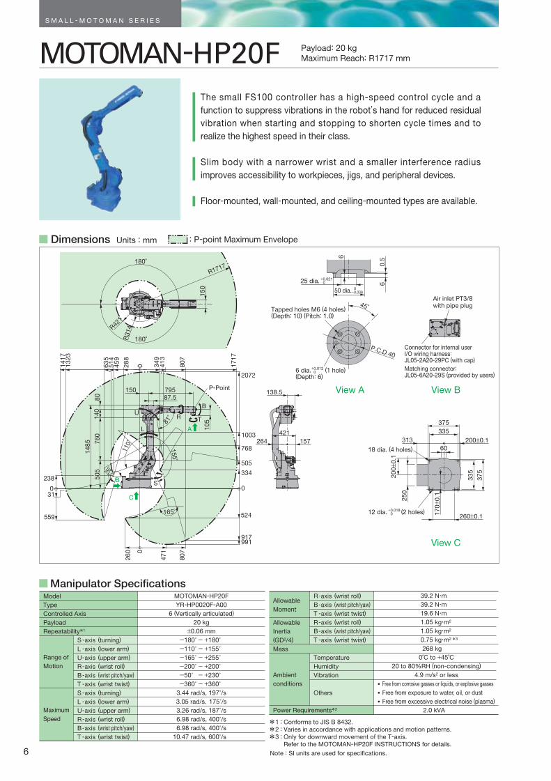
Manipulator SpecificationsMOTOMAN-HP20F
YR-HP0020F-A00
6 (Vertically articulated)
20 kg
±0.06 mm
-180° - +180°-110° - +155°-165° - +255°-200° - +200°-50° - +230°-360° - +360°
3.44 rad/s, 197°/s3.05 rad/s,175°/s3.26 rad/s, 187°/s6.98 rad/s, 400°/s6.98 rad/s, 400°/s
10.47 rad/s, 600°/s
39.2 N m
39.2 N m
19.6 N m
1.05 kg m2
1.05 kg m2
0.75 kg m2 *3
268 kg
0˚C to +45˚C
20 to 80%RH (non-condensing)
4.9 m/s2 or less
2.0 kVA
Free from corrosive gasses or liquids, or explosive gasses
Free from exposure to water, oil, or dust
Free from excessive electrical noise (plasma)
***
123
:::
Conforms to JIS B 8432. Varies in accordance with applications and motion patterns.Only for downward movement of the T-axis.Refer to the MOTOMAN-HP20F INSTRUCTIONS for details.
Note : SI units are used for specifications.
MOTOMAN-HP20F Payload: 20 kg
Maximum Reach: R1717 mm
The small FS100 controller has a high-speed control cycle and a
function to suppress vibrations in the robot’s hand for reduced residual
vibration when starting and stopping to shorten cycle times and to
realize the highest speed in their class.
Slim body with a narrower wrist and a smaller interference radius
improves accessibility to workpieces, jigs, and peripheral devices.
Floor-mounted, wall-mounted, and ceiling-mounted types are available.
Dimensions Units : mm : P-point Maximum Envelope
Range of
Motion
Maximum
Speed
Model
Type
Controlled Axis
Payload
Repeatability*1
(turning)
(lower arm)
(upper arm)
(wrist roll)
(wrist pitch/yaw)
(wrist twist)
(turning)
(lower arm)
(upper arm)
(wrist roll)
(wrist pitch/yaw)
(wrist twist)
-axis
-axis
-axis
-axis
-axis
-axis
-axis
-axis
-axis
-axis
-axis
-axis
S
L
U
R
B
T
S
L
U
R
B
T
Allowable
Moment
Allowable
Inertia
(GD2/4)
Ambient
conditions
Power Requirements*2
Mass
(wrist roll)
(wrist pitch/yaw)
(wrist twist)
(wrist roll)
(wrist pitch/yaw)
(wrist twist)
-axis
-axis
-axis
-axis
-axis
-axis
Temperature
Humidity
Vibration
Others
R
B
T
R
B
T
2072
81˚
559
238
0
76
0
14
85
0
26
0
47
1
80
7
991917
155
˚
165˚
110˚
524
0
334
505
768
1003
14
08
0
13
23
14
17
87.5150 795
051
46
35
45
9
28
8
34
94
13
10
5
80
7
17
17
P-Point
L
B
TRU
S
180˚
180˚
R42
1
R1717
R314
150
138.5
157264
A
B
C
421
50
5 255˚
6
Connector for internal userI/O wiring harness: JL05-2A20-29PC (with cap)
Matching connector:JL05-6A20-29S (provided by users)
Air inlet PT3/8with pipe plug
18 dia. (4 holes)
20
0± 0
.1
260±0.1
17
0± 0
.1
25
0
37
5
33
5
200±0.1313
335
375
45˚Tapped holes M6 (4 holes)(Depth: 10) (Pitch: 1.0)
P.C.D.40
View A View B
View C
60
+0.01206 dia. (1 hole)
(Depth: 6)
+0.018012 dia. (2 holes)
31
0.5
6
6
+0.021025 dia.
0−0.03950 dia.

S M A L L - M O T O M A N S E R I E S
Operation Screen
Easy pre-examination
For cell simulation, an easy pre-examination is available on your
PC by optional high-speed 3D graphics MotoSim EG*.
It also supports ROBCAD and IGRIP for the line simulation.
The FS100 is a compact controller with improved performance and functions optimized for
handling and assembly. Can be used with robots with a 20-kg payload or less.
MotoPlus
・・・・・・・
Sophisticated and flexible robot control programs that were not possible with INFORM and CIO ladder programs can be developed by using C languages.
Customization of programming pendantOperation windows for the programming pendant can be customized using VC++ and C# languages in accordance with needs and applications.
Interface panels
The windows in the operation panel can be created to look the same in the programming pendant.
High-speed Compact Controller for Handling FS100
Hardware Options Optional Functions
・・・・・・・・・
FS100 Controller Specifications Programming Pendant Specifications Optional
Optional
Optional
Optional
Conveyor synchronization
TCP
Relative job
Coordinated control
Servo float
Energy saving mode (with servomotor turn off limit)
Software pendant
Network (data transfer, FTP, Ethernet server)
Bilingual display (Shown in the required language.)
・・・・・
Vision function
External reference point control
Independent control
Search
Automatic backup
Optimum controller for handling and assembly
Custom-made functions and windows can be created for various purposes and users.
Open controller
* :
Note :MOTOMAN Simulator Enhanced Graphics
ROBCAD is a registered trademark of UGS Corp.IGRIP is a registered trademark of DELMIA Corp.
**
12
::For the MOTOMAN-MH3F, -MH5F, or -MH5LFFor the MOTOMAN-MH6F or -HP20F
Fits in a 19-inch rack and can be installed under conveyors.
Improved performance and high-speed control obtained by improving resolutions for I/O commands as well as by reducing time for ladder scanning.
High-speed positioning achieved by suppressing vibration of hands.
Commands specifically designed for workpiece handling with synchronized conveyors.
Programming pendant
IP54 protective structure
External axis (max.: 2 axes)
I/O module (28 points, NPN or PNP)
Counter module (2 channels)
Analog I/O module (8 channels)
Major fieldbus interface boards
DeviceNet (master/slave), CC-Link (slave), PROFIBUS (slave), Ethernet/IP (slave, I/O communications)
Items
Configuration
Dimensions
Mass
Cooling System
Ambient
Temperature
Relative Humidity
Power Supply
Grounding
Digital l/Os
Positioning System
Programming
Capacity
Expansion Slots
LAN (Connection to Host)
Interface
Control Method
Drive Units
Painting Color
Standard: IP20 (open structure), Option: IP54 (dustproof housing)
470 (W)×420 (D)×200 (H) mm (Protrusions are not included.)
20 kg
Direct cooling
During operation: 0˚C to +40˚C
During storage : ‒10˚C to +60˚C
90% max. (non-condensing)
Single-phase 200/230 VAC (+10% to ‒15%), 50/60 Hz*1
Three-phase 200/220 VAC (+10% to ‒15%), 50/60 Hz*2
Grounding resistance: 100 Ω or less
Specialized signals: 10 inputs and 1 output
General signals : 28 inputs and 28 outputs
Max. I/O (optional) : 1,024 inputs and 1,024 outputs
By serial encoder
JOB: 10,000 steps, 1,000 instructions
CIO ladder: 1,500 steps
MP2000 bus × 5 slots
1 (10BASE-T/100BASE-TX)
RS-232C: 1ch
Software servo control
Six axes for robots
Two more axes can be added as external axes. (Can be installed in the controller.)
Munsell notation 5Y7/1 (reference value)
Items
Dimensions
Mass
Material
Operation
Device
Display
IEC Protection Class
Cable Length
169 (W)×314.5 (H)×50 (D) mm
0.990 kg
Reinforced plastics
Select keys, axis keys (8 axes), numerical/application
keys, Mode switch with key (mode: teach, play, and
remote), emergency stop button, enable switch, compact
flash card interface device (compact flash is optional.),
USB port (1 port)
640×480 pixels color LCD, touch panel
(Alphanumeric characters, Chinese characters, Japanese letters, Others)
IP65
Standard: 8 m, optional: 20 m max.
SpecificationsSpecifications
Note: A programming pendant or a dummy connector is required with the FS100. (Sold separately.)
Programming pendant (model: JZRCR-YPP03-1) For maintenance, the programming pendant is required. One programming pendant can be used with more than one controller.
Dummy connector (model: CBL-FRC063-1)
The dummy connector must be inserted when the programming pendant is not connected or when the software pendant is used.
The programming pendant (YPP01-1) for a DX100 controller cannot be connected to the FS100 controller because of differences in their specifications.
7
Small-MOTOMAN Series
LITERATURE NO. KAEP C940440 06C
Published in Japan February 2012 05-11 2
Specifications are subject to change without notice for ongoing product modifications and improvements.
© 2005-2012 YASKAWA ELECTRIC CORPORATION. All rights reserved.
YASKAWA ELECTRIC CORPORATION
In the event that the end user of this product is to be the military and said product is to be employed in any weapons systems or the manufacture thereof, the export will fall under the relevant regulations as stipulated in the Foreign Exchange and Foreign Trade Regulations. Therefore, be sure to follow all procedures and submit all relevant documentation according to any and all rules, regulations and laws that may apply.
Sales Department
12-1-29
HEAD OFFICE2-1 Kurosaki-Shiroishi, Yahatanishi-ku, Kitakyushu, Fukuoka 806-0004, JapanPhone: +81-93-645-7745 Fax: +81-93-645-7746
YASKAWA America, Inc.100 Automation Way, Miamisburg, OH 45342, U.S.A.Phone: +1-937-847-6200 Fax: +1-937-847-6277
YASKAWA Europe GmbHKammerfeldstr. 1, 80591 Allershausen, GermanyPhone: +49-8166-90-0 Fax: +49-8166-90-103
YASKAWA Nordic ABBredbandet 1vån. 3 varvsholmen 392 30 Kalmar, SwedenPhone: +46-480-417-800 Fax: +46-480-417-999
YASKAWA Electric (China) Co., Ltd.12F, Carlton Bldg., No.21 HuangHe Road, HuangPu District, Shanghai 200003, ChinaPhone: +86-21-5385-2200 Fax: +86-21-5385-3299
YASKAWA SHOUGANG ROBOT CO., LTD.No.7 Yongchang North Road, Beijing E&T Development Area China 100176Phone: +86-10-6788-2858 Fax: +86-10-6788-2878
YASKAWA Robotics India Limited#426, Udyog Vihar Phase-IV, Gurgaon, Haryana, IndiaPhone: +91-124-475-8500 Fax: +91-124-475-8542
YASKAWA Electric Korea Co., Ltd9F, Kyobo Securities Bldg., 26-4, Yeouido-dong, Yeongdeungpo-gu, Seoul 150-737, KoreaPhone: +82-2-784-7844 Fax: +82-2-784-8495
YASKAWA Electric (Singapore) PTE Ltd151 Lorong Chuan, #04-02A New Tech Park, Singapore 556741Phone: +65-6282-3003 Fax: +65-6289-3003
YASKAWA Electric (Thailand) Co. Ltd.252/246, 4th Floor Muang Thai-Phatra Office Tower 2 Rachadapisek Road,Huaykwang Bangkok, 10320 ThailandPhone: +66-2-693-2200 Fax: +66-2-693-4200