road vehicles — test methods for electrical disturbances
TRANSCRIPT

Reference numberISO 10605:2008(E)
© ISO 2008
INTERNATIONAL STANDARD
ISO10605
Second edition2008-07-15
Road vehicles — Test methods for electrical disturbances from electrostatic discharge
Véhicules routiers — Méthodes d'essai des perturbations électriques provenant de décharges électrostatiques
Vervielfältigt mit Erlaubnis der ISO International Organization for Standardization, erteilt durch DIN Deutsches Institut für Normung e.V., in das interne Netzwerk der TÜV Rheinland Group eingespeichert.
ISO 10605:2008(E)
PDF disclaimer This PDF file may contain embedded typefaces. In accordance with Adobe's licensing policy, this file may be printed or viewed but shall not be edited unless the typefaces which are embedded are licensed to and installed on the computer performing the editing. In downloading this file, parties accept therein the responsibility of not infringing Adobe's licensing policy. The ISO Central Secretariat accepts no liability in this area.
Adobe is a trademark of Adobe Systems Incorporated.
Details of the software products used to create this PDF file can be found in the General Info relative to the file; the PDF-creation parameters were optimized for printing. Every care has been taken to ensure that the file is suitable for use by ISO member bodies. In the unlikely event that a problem relating to it is found, please inform the Central Secretariat at the address given below.
COPYRIGHT PROTECTED DOCUMENT © ISO 2008 All rights reserved. Unless otherwise specified, no part of this publication may be reproduced or utilized in any form or by any means, electronic or mechanical, including photocopying and microfilm, without permission in writing from either ISO at the address below or ISO's member body in the country of the requester.
ISO copyright office Case postale 56 • CH-1211 Geneva 20 Tel. + 41 22 749 01 11 Fax + 41 22 749 09 47 E-mail [email protected] Web www.iso.org
Published in Switzerland
ii © ISO 2008 – All rights reserved
Vervielfältigt mit Erlaubnis der ISO International Organization for Standardization, erteilt durch DIN Deutsches Institut für Normung e.V., in das interne Netzwerk der TÜV Rheinland Group eingespeichert.
ISO 10605:2008(E)
© ISO 2008 – All rights reserved iii
Contents Page
Foreword............................................................................................................................................................ iv Introduction ........................................................................................................................................................ v 1 Scope ..................................................................................................................................................... 1 2 Normative references ........................................................................................................................... 1 3 Terms and definitions........................................................................................................................... 1 4 Test conditions ..................................................................................................................................... 3 5 Test location.......................................................................................................................................... 3 6 Test apparatus and instrumentation................................................................................................... 3 6.1 ESD generator ....................................................................................................................................... 3 6.2 Discharge tips ....................................................................................................................................... 4 6.3 Discharge current specifications ........................................................................................................ 4 6.4 Coupling and ground reference planes.............................................................................................. 6 6.5 Insulation block..................................................................................................................................... 6 6.6 Insulation support................................................................................................................................. 7 7 Discharge modes .................................................................................................................................. 7 7.1 General................................................................................................................................................... 7 7.2 Contact discharge mode...................................................................................................................... 7 7.3 Air discharge mode .............................................................................................................................. 7 8 Component immunity test method (powered-up test) ...................................................................... 7 8.1 General................................................................................................................................................... 7 8.2 Test plan ................................................................................................................................................ 8 8.3 Test procedure for direct discharges ................................................................................................. 8 8.4 Test procedure for indirect discharges ............................................................................................ 10 9 Component packaging and handling test method (unpowered test)............................................ 12 9.1 General................................................................................................................................................. 12 9.2 Test plan .............................................................................................................................................. 12 9.3 Test procedure .................................................................................................................................... 12 10 Vehicle test method............................................................................................................................ 15 10.1 General................................................................................................................................................. 15 10.2 Test plan .............................................................................................................................................. 15 10.3 Test procedure .................................................................................................................................... 15 11 Test report ........................................................................................................................................... 18 Annex A (normative) Current target specification and verification of ESD generator ............................. 19 Annex B (informative) Standard target drawings and target verification method..................................... 23 Annex C (informative) Function performance status classification (FPSC) .............................................. 35 Annex D (informative) Test method guidance — Generator resistor value and air or contact
discharge ............................................................................................................................................. 39 Annex E (informative) Rationale for air discharge generator verification.................................................. 42 Annex F (informative) Optional test set-up and procedure for electronic modules (powered-up
test)....................................................................................................................................................... 44 Bibliography ..................................................................................................................................................... 50
Vervielfältigt mit Erlaubnis der ISO International Organization for Standardization, erteilt durch DIN Deutsches Institut für Normung e.V., in das interne Netzwerk der TÜV Rheinland Group eingespeichert.
ISO 10605:2008(E)
iv © ISO 2008 – All rights reserved
Foreword
ISO (the International Organization for Standardization) is a worldwide federation of national standards bodies (ISO member bodies). The work of preparing International Standards is normally carried out through ISO technical committees. Each member body interested in a subject for which a technical committee has been established has the right to be represented on that committee. International organizations, governmental and non-governmental, in liaison with ISO, also take part in the work. ISO collaborates closely with the International Electrotechnical Commission (IEC) on all matters of electrotechnical standardization.
International Standards are drafted in accordance with the rules given in the ISO/IEC Directives, Part 2.
The main task of technical committees is to prepare International Standards. Draft International Standards adopted by the technical committees are circulated to the member bodies for voting. Publication as an International Standard requires approval by at least 75 % of the member bodies casting a vote.
Attention is drawn to the possibility that some of the elements of this document may be the subject of patent rights. ISO shall not be held responsible for identifying any or all such patent rights.
ISO 10605 was prepared by Technical Committee ISO/TC 22, Road vehicles, Subcommittee SC 3, Electrical and electronic equipment.
This second edition cancels and replaces the first edition (ISO 10605:2001), which has been technically revised.
Vervielfältigt mit Erlaubnis der ISO International Organization for Standardization, erteilt durch DIN Deutsches Institut für Normung e.V., in das interne Netzwerk der TÜV Rheinland Group eingespeichert.
ISO 10605:2008(E)
© ISO 2008 – All rights reserved v
Introduction
The familiar electrostatic discharge, due to former charge build-ups generated, for example, when moving about inside a vehicle or getting out of it, has assumed greater significance with the increase of vehicle electronic modules. Tests simulating the electrostatic discharge of humans, in common use by various industries, were examined and it was determined that they were not fully applicable to the automotive environment. As a consequence, tests tailored to the automotive environment were developed.
Tests that simulate an electrostatic discharge (ESD) into a vehicle electrical system are based on the human ESD model. Sensitive electrical devices can be adversely affected by energy either coupled or radiated from electrostatic discharges. This International Standard describes ESD tests that are applicable to both automotive electronic modules and vehicles.
Vervielfältigt mit Erlaubnis der ISO International Organization for Standardization, erteilt durch DIN Deutsches Institut für Normung e.V., in das interne Netzwerk der TÜV Rheinland Group eingespeichert.

This page is intentionally blank.
Vervielfältigt mit Erlaubnis der ISO International Organization for Standardization, erteilt durch DIN Deutsches Institut für Normung e.V., in das interne Netzwerk der TÜV Rheinland Group eingespeichert.
INTERNATIONAL STANDARD ISO 10605:2008(E)
© ISO 2008 – All rights reserved 1
Road vehicles — Test methods for electrical disturbances from electrostatic discharge
1 Scope
This International Standard specifies the electrostatic discharge (ESD) test methods necessary to evaluate electronic modules intended for vehicle use. It applies to discharges in the following cases:
⎯ ESD in assembly;
⎯ ESD caused by service staff;
⎯ ESD caused by occupants.
ESD applied to the device under test (DUT) can directly influence the DUT. ESD applied to neighbouring parts can couple into supply and signal lines of the DUT in the vehicle and/or directly into the DUT.
This International Standard describes test procedures for evaluating both electronic modules on the bench and complete vehicles. This International Standard applies to all types of road vehicles regardless of the propulsion system (e.g. spark-ignition engine, diesel engine, electric motor).
This International Standard is based in part on IEC 61000-4-2 and describes vehicle-specific requirements.
This International Standard does not apply to pyrotechnic modules.
2 Normative references
The following referenced documents are indispensable for the application of this document. For dated references, only the edition cited applies. For undated references, the latest edition of the referenced document (including any amendments) applies.
ISO 7637-1, Road vehicles — Electrical disturbances from conduction and coupling — Part 1: Definitions and general considerations
ISO 11452-1, Road vehicles — Component test methods for electrical disturbances from narrowband radiated electromagnetic energy — Part 1: General principles and terminology
3 Terms and definitions
For the purposes of this document, the terms and definitions given in ISO 7637-1 and ISO 11452-1 and the following apply.
3.1 air discharge test method characterized by bringing the test generator electrode close to the device under test (DUT); the discharge is by arcing on the DUT
Vervielfältigt mit Erlaubnis der ISO International Organization for Standardization, erteilt durch DIN Deutsches Institut für Normung e.V., in das interne Netzwerk der TÜV Rheinland Group eingespeichert.
ISO 10605:2008(E)
2 © ISO 2008 – All rights reserved
3.2 contact discharge test method characterized by contact of the test generator electrode with the DUT, where discharge is initiated by the generator discharge switch
3.3 device under test DUT single component or combination of components as defined to be tested
3.4 direct discharge discharge directly on the DUT
3.5 electrostatic discharge ESD transfer of electrostatic charge between bodies at different potentials occurring prior to contact or induced by an electrostatic field
3.6 ESD generator instrument that simulates the human ESD model
3.7 ground reference plane GRP flat conductive surface whose potential is used as a common reference
NOTE Where applicable, it is advisable that the test voltage of the DUT and the operator ground also be referenced to the ground plane.
3.8 holding time interval of time within which the decrease of the test voltage due to leakage, prior to the discharge, is 10 %
3.9 horizontal coupling plane HCP metal plane oriented in horizontal direction, to which discharges are applied to simulate electrostatic discharge to objects adjacent to the DUT
3.10 human ESD model network of passive elements and voltage that characterizes a charged person as a source of an electrostatic discharge for automotive conditions
3.11 indirect discharge discharge on a coupling plane near the DUT
NOTE Discharge current produces a transient field that might affect the DUT. Indirect discharge simulates discharge by a human being on items near the DUT.
3.12 surface uninterrupted housing area, gap or opening
EXAMPLE Switches, tip switches, points of contact, air vents, speaker openings.
Vervielfältigt mit Erlaubnis der ISO International Organization for Standardization, erteilt durch DIN Deutsches Institut für Normung e.V., in das interne Netzwerk der TÜV Rheinland Group eingespeichert.

ISO 10605:2008(E)
© ISO 2008 – All rights reserved 3
4 Test conditions
The user shall specify the test severity level(s) for the component and vehicle tests. Suggested test levels are included in Annex C.
Standard test conditions shall be as follows:
⎯ ambient temperature: (25 ± 10) °C;
⎯ relative humidity between 20 % and 60 % (20 °C and 30 % relative humidity preferred).
If other values are agreed to by the users, these values shall be documented in the test report.
5 Test location
Special locations, such as shielded enclosures or even absorber-lined shielded enclosures, are allowed but not required.
NOTE ESD testing creates transient fields, which can interfere with sensitive electronic devices or receivers, even at a distance of a few meters. It is advisable that this be considered when choosing a test location.
6 Test apparatus and instrumentation
6.1 ESD generator
The ESD generator characteristics shall be as specified in Table 1.
Table 1 — General ESD generator parameters
Parameter Characteristic
Output voltage range contact discharge mode 2 kV to 15 kV, or as required in the test plan a
Output voltage range air discharge mode 2 kV to 25 kV, or as required in the test plan a
Output voltage accuracy u 5 %
Output polarity Positive and negative
Rise time of short circuit current in contact discharge mode (10 % to 90 %) 0,7 ns to 1,0 ns
Holding time W 5 s
Storage capacitances 150 pF, 330 pF
Discharge resistances 330 Ω, 2 000 Ω a See examples in Annex C.
NOTE When an ESD generator is supplied from an external supply source (a.c. or d.c.) or controlled by a separate unit and this/these cable(s) is/are not combined (bundled) with the ESD generator discharge return cable, unintended current can flow through this/these cable(s).
The ESD generator should be able to generate a repetition rate of at least 10 discharges per second down to manual control without any degradation of the discharge current waveform.
In cases where a 2 m length of the discharge return cable is insufficient (e.g. for tall DUTs), a length not exceeding 3 m may be used and compliance with the waveform specifications shall be guaranteed (e.g. by the manufacturer or from calibration).
Vervielfältigt mit Erlaubnis der ISO International Organization for Standardization, erteilt durch DIN Deutsches Institut für Normung e.V., in das interne Netzwerk der TÜV Rheinland Group eingespeichert.
ISO 10605:2008(E)
4 © ISO 2008 – All rights reserved
6.2 Discharge tips
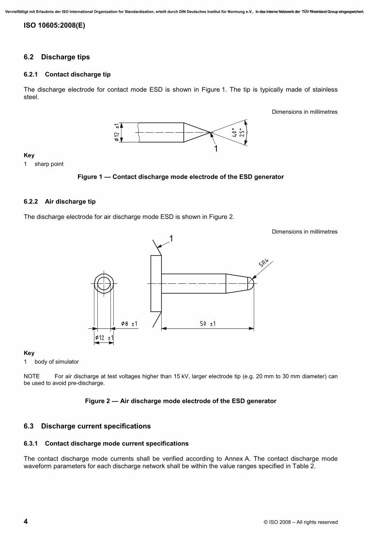
6.2.1 Contact discharge tip
The discharge electrode for contact mode ESD is shown in Figure 1. The tip is typically made of stainless steel.
Dimensions in millimetres
Key 1 sharp point
Figure 1 — Contact discharge mode electrode of the ESD generator
6.2.2 Air discharge tip
The discharge electrode for air discharge mode ESD is shown in Figure 2.
Dimensions in millimetres
Key 1 body of simulator
NOTE For air discharge at test voltages higher than 15 kV, larger electrode tip (e.g. 20 mm to 30 mm diameter) can be used to avoid pre-discharge.
Figure 2 — Air discharge mode electrode of the ESD generator
6.3 Discharge current specifications
6.3.1 Contact discharge mode current specifications
The contact discharge mode currents shall be verified according to Annex A. The contact discharge mode waveform parameters for each discharge network shall be within the value ranges specified in Table 2.
Vervielfältigt mit Erlaubnis der ISO International Organization for Standardization, erteilt durch DIN Deutsches Institut für Normung e.V., in das interne Netzwerk der TÜV Rheinland Group eingespeichert.
ISO 10605:2008(E)
© ISO 2008 – All rights reserved 5
Table 2 — Contact discharge mode current specifications
Typical capacitance/ resistance
values
Peak current/ charge voltage Tolerance Current at t1 /
charge voltage Tolerance Current at t2 / charge voltage Tolerance
A/kV % A/kV % A/kV %
150 pF / 330 Ω 3,75 ± 10 2 (at t1 = 30 ns) ± 30 1
(at t2 = 60 ns) ± 30
330 pF / 330 Ω 3,75 ± 10 2 (at t1 = 65 ns) ± 30 1
(at t2 = 130 ns) ± 30
150 pF / 2 000 Ω 3,75 300
+
0,275 (at t1 = 180 ns) ± 30 0,15
(at t2 = 360 ns) ± 50
330 pF / 2 000 Ω 3,75 300
+
0,275 (at t1 = 400 ns) ± 30 0,15
(at t2 = 800 ns) ± 50
NOTE 1 The peak current level is taken from the measurement system without any data interpolation.
NOTE 2 The target used with this measurement system fulfils the requirements of Clauses A.1 and A.2. An example is defined in Annex B.
NOTE 3 The measurement times (30 ns, 60 ns, 65 ns, 130 ns, 180 ns, 360 ns, 400 ns and 800 ns) are derived from the resistance-capacitive (RC) time constant − 40 % (current t1) and + 20 % (current t2), to define two values on the falling slope of the current pulse in accordance with IEC 61000-4-2.
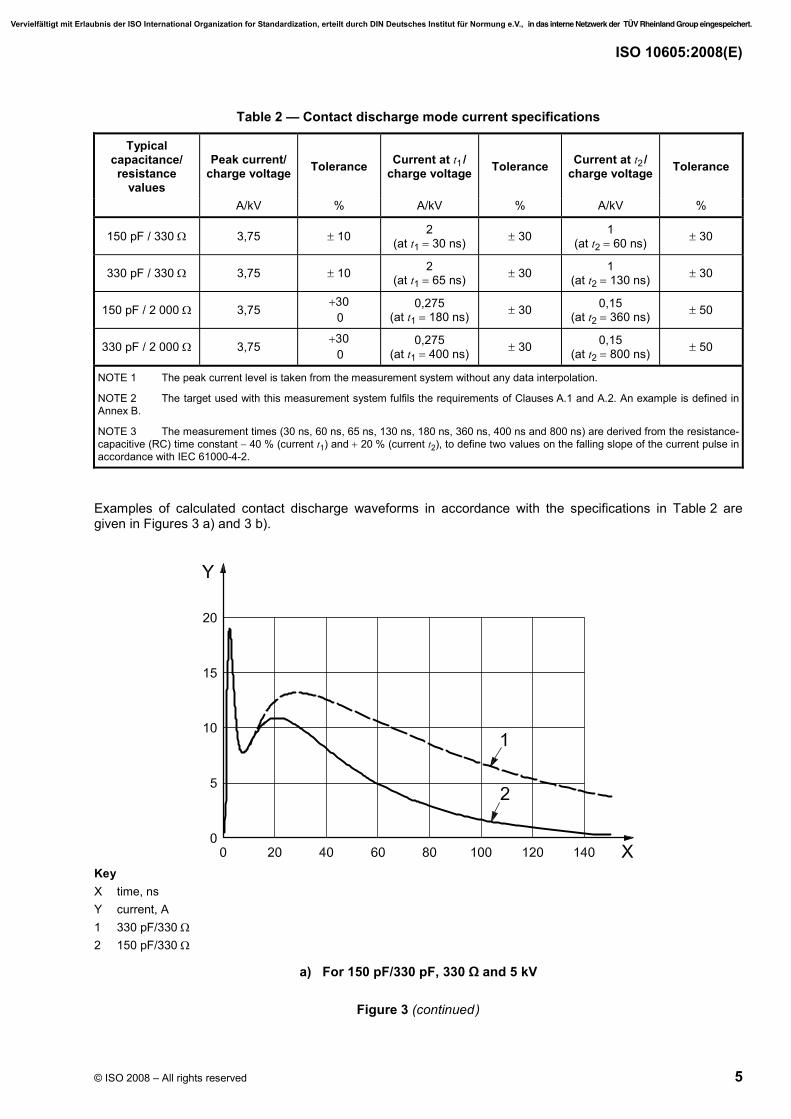
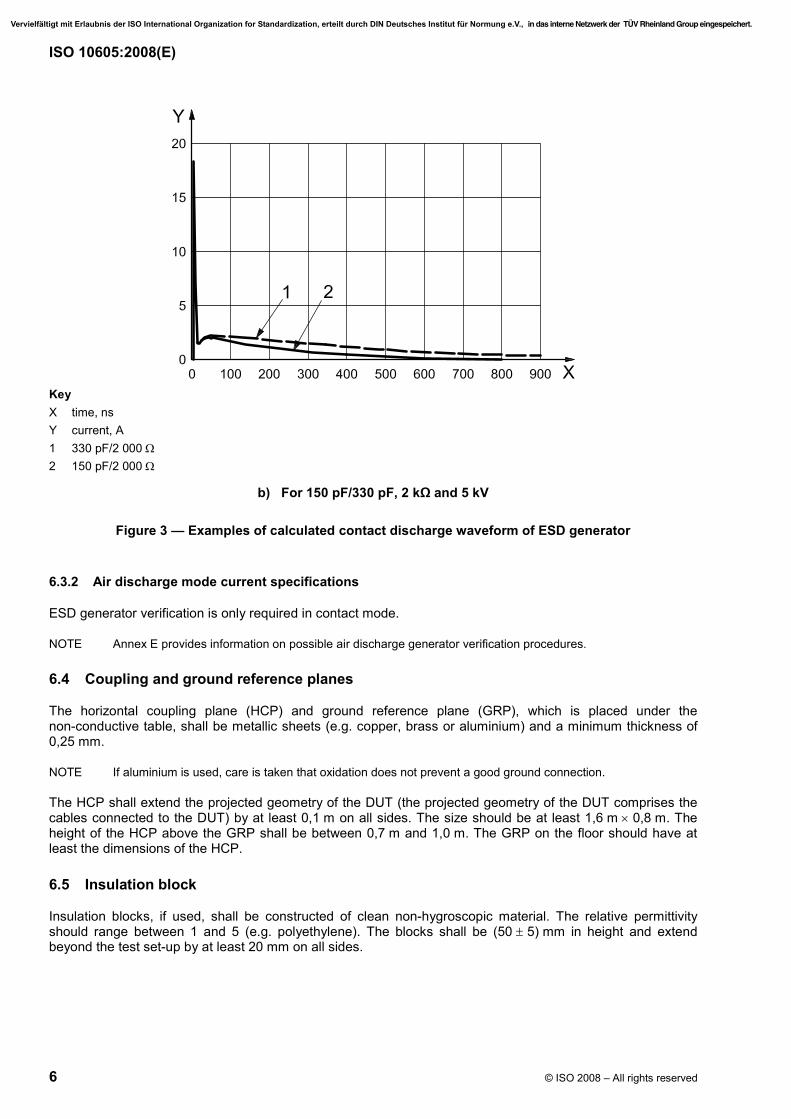
Examples of calculated contact discharge waveforms in accordance with the specifications in Table 2 are given in Figures 3 a) and 3 b).
Key X time, ns Y current, A 1 330 pF/330 Ω 2 150 pF/330 Ω
a) For 150 pF/330 pF, 330 Ω and 5 kV
Figure 3 (continued)
Vervielfältigt mit Erlaubnis der ISO International Organization for Standardization, erteilt durch DIN Deutsches Institut für Normung e.V., in das interne Netzwerk der TÜV Rheinland Group eingespeichert.
ISO 10605:2008(E)
6 © ISO 2008 – All rights reserved
Key X time, ns Y current, A 1 330 pF/2 000 Ω 2 150 pF/2 000 Ω
b) For 150 pF/330 pF, 2 kΩ and 5 kV
Figure 3 — Examples of calculated contact discharge waveform of ESD generator
6.3.2 Air discharge mode current specifications
ESD generator verification is only required in contact mode.
NOTE Annex E provides information on possible air discharge generator verification procedures.
6.4 Coupling and ground reference planes
The horizontal coupling plane (HCP) and ground reference plane (GRP), which is placed under the non-conductive table, shall be metallic sheets (e.g. copper, brass or aluminium) and a minimum thickness of 0,25 mm.
NOTE If aluminium is used, care is taken that oxidation does not prevent a good ground connection.
The HCP shall extend the projected geometry of the DUT (the projected geometry of the DUT comprises the cables connected to the DUT) by at least 0,1 m on all sides. The size should be at least 1,6 m × 0,8 m. The height of the HCP above the GRP shall be between 0,7 m and 1,0 m. The GRP on the floor should have at least the dimensions of the HCP.
6.5 Insulation block
Insulation blocks, if used, shall be constructed of clean non-hygroscopic material. The relative permittivity should range between 1 and 5 (e.g. polyethylene). The blocks shall be (50 ± 5) mm in height and extend beyond the test set-up by at least 20 mm on all sides.
Vervielfältigt mit Erlaubnis der ISO International Organization for Standardization, erteilt durch DIN Deutsches Institut für Normung e.V., in das interne Netzwerk der TÜV Rheinland Group eingespeichert.

ISO 10605:2008(E)
© ISO 2008 – All rights reserved 7
6.6 Insulation support
Insulation support, if used, shall be constructed of clean non-hygroscopic material with a relative permittivity between 1 and 5 (e.g. polyethylene). The support shall be between 2 mm and 3 mm in height and project beyond the test set-up by at least 20 mm on all sides. Care shall be taken that support prevents dielectric breakdown up to 25 kV.
7 Discharge modes
7.1 General
Discharges can be applied by two discharge modes: contact and air. See Annex D for guidance on air versus contact discharge modes.
7.2 Contact discharge mode
In contact discharge mode, the tip of the ESD generator's discharge electrode is brought in contact with the DUT before the discharge switch is actuated to apply the discharge.
7.3 Air discharge mode
In air discharge mode, the discharge electrode is charged to the test voltage and then brought with the demanded speed of approach to the DUT, applying the discharge through an arc that happens when the tip approaches close enough to the DUT to break down the dielectric material between the tip and test point.
The speed of approach of the discharge electrode is a critical factor in the rise time and amplitude of the injected current during an air discharge. The speed of approach should be between 0,1 m/s and 0,5 m/s for any test. Because the approach speed is not trivial to measure, in practice the ESD generator should approach the DUT as quickly as possible until the discharge occurs or the discharge tip touches the discharge point without causing damage to the DUT or generator.
8 Component immunity test method (powered-up test)
8.1 General
These tests consist of direct and indirect types of application of discharges to the DUT, as follows:
⎯ direct type discharges (contact or air discharge mode) are applied directly to the DUT and to the remote parts that are accessible by the vehicle users, e.g. switches and buttons (see 8.3);
⎯ indirect type discharges (contact discharge mode) simulate discharges that occur to other conductive objects in the vicinity of the DUT and are applied through an intervening metal, such as an HCP (see 8.4).
NOTE An optional field coupling test with direct discharge test method is described in Annex F.
For the test of electronic modules, the ESD generator shall be configured with the 330 pF or 150 pF capacitor, depending on the DUT location in the vehicle (see 10.1), and the 330 Ω resistor. If the DUT location is not specified, the 330 pF capacitor shall be used.
Conductive surfaces shall be tested using contact mode discharges. For contact discharge, use the contact discharge tip (see Figure 1). Air discharge may also be applied to conductive surfaces, if required in the test plan.
Non-conductive surfaces shall be tested using air mode discharges. For air discharge, use the air discharge tip (see Figure 2).
Vervielfältigt mit Erlaubnis der ISO International Organization for Standardization, erteilt durch DIN Deutsches Institut für Normung e.V., in das interne Netzwerk der TÜV Rheinland Group eingespeichert.

ISO 10605:2008(E)
8 © ISO 2008 – All rights reserved
Before applying any discharges to the DUT, verify that the ESD generator discharge verification procedure, as specified in Annex A, has been performed within the time period established by the laboratory or the customer.
8.2 Test plan
Prior to performing the test, generate a test plan, including the following:
⎯ the detailed test set-up;
⎯ test points;
⎯ electronic module mode of operation;
⎯ any special instructions and changes from the standard test.
8.3 Test procedure for direct discharges
8.3.1 General
Discharges shall be applied to all specified test points with the equipment operating in normal modes. Product response may be affected by the polarity of the discharge. Both polarities of discharge shall be used during testing to determine their effect on the DUT.
NOTE An optional field coupling test with direct discharge test method is described in Annex F.
8.3.2 Test set-up
Place the DUT on the HCP (see Figure 4). Place and connect chassis-mounted electronic modules directly to the HCP. Test electronic modules, which will be isolated from the ground in normal installation with an insulator between the electronic module and the HCP using insulation support (see 6.6).
For testing, the DUT shall be connected to all peripheral units necessary for functional testing. The line lengths used should be between 1,50 m and 2,50 m.
If vehicle intent peripheral units are not available for testing, substitute peripheral units and test discharge points shall be addressed in the test plan.
All components on the test table shall be a minimum distance of 0,2 m from each other. The lines shall be laid in such a way that they run parallel to the HCP edges and the plane and, like all components, they shall be a distance of 0,1 m away from the HCP edges. The lines should be bundled and shall be secured on an insulating block, in accordance with 6.5. The wiring type is defined by the actual system application and requirement.
The supply battery shall be on the test table, with the negative terminal of the battery directly connected to the HCP. The explosion hazard of the battery shall be taken into account and appropriate protective measures taken.
For direct discharge, the discharge return cable of the ESD generator shall be connected to the HCP, as shown in Figure 4.
The ESD test bench (test surface) shall be a minimum of 0,1 m from other conductive structures, such as the surfaces of a shielded room.
The same generator discharge return cable to the HCP shall be used for verification and testing. While the discharge is being applied, the discharge return cable of the generator shall be kept at least 0,2 m away from the DUT and all cables connected to the DUT (to reduce coupling from this cable which might affect the test results).
Vervielfältigt mit Erlaubnis der ISO International Organization for Standardization, erteilt durch DIN Deutsches Institut für Normung e.V., in das interne Netzwerk der TÜV Rheinland Group eingespeichert.

ISO 10605:2008(E)
© ISO 2008 – All rights reserved 9
Key 1 DUT 9 periphery 2 ESD generator 10 battery 3 ESD generator main unit 11 isolating support, if required 4 non-conductive table 12 insulating blocks 5 HCP 13 470 kΩ resistors 6 ground point 14 GRP optional 7 ground connection 15 HCP ground connection 8 remotely accessible parts of the DUT
Figure 4 — Test set-up example for testing powered DUT immunity to direct ESD
8.3.3 Electrode connections for direct discharge method
8.3.3.1 Contact discharge mode
In the case of contact discharges, the tip of the discharge electrode (see Figure 1) shall touch a conducting point on the DUT before the discharge switch is actuated.
Where painted surfaces cover a conducting substrate, the following procedure is used. If the coating is not declared to be an insulating coating by the equipment manufacturer, then the pointed tip of the generator penetrates the coating so as to make contact with the conducting substrate.
8.3.3.2 Air discharge mode
In the case of air discharges, the tip of the discharge electrode (see Figure 2) shall be brought sufficiently close to the DUT as quickly as possible after the discharge switch is actuated (see 7.3).
Where painted surfaces cover a conducting substrate or dielectric surfaces are used as boxes, the following procedure is used. If the coating is declared to be an insulating coating for the dielectric surfaces, then the surface is tested as an insulating surface using the air discharge mode.
Vervielfältigt mit Erlaubnis der ISO International Organization for Standardization, erteilt durch DIN Deutsches Institut für Normung e.V., in das interne Netzwerk der TÜV Rheinland Group eingespeichert.

ISO 10605:2008(E)
10 © ISO 2008 – All rights reserved
8.3.4 Orientation of ESD generator
For direct discharge, the ESD generator's discharge tip is held perpendicular to the surface of the DUT when possible; if not possible, an angle of at least 45° to the surface of the DUT is preferred.
8.3.5 Number of discharges and time between ESD events
At least 3 discharges shall be applied to all direct discharge test points for each specified test voltage and polarity (see Annex C). The time interval between successive single discharges shall be as long as necessary in order to allow charges that were built up due to the tests to dissipate, but not less than 1 s, in order to ensure that the charges are removed before each new discharge. The methods described below can be applied.
⎯ Charge build-up can be eliminated by briefly connecting a bleeder wire with high resistance (W 1 MΩ) in the following sequence: (1) between the discharge location and ground, and (2) between the ground point of the DUT and ground. If there is evidence that the wire does not have any impact on the test result, it can remain connected to the DUT.
⎯ If the time interval is lengthened between two successive discharges, the build-up charge vanishes due to the natural charge decay.
⎯ Air-ionizers may be used to speed up the “natural” discharging process of the DUT to its environment. The ionizer shall be turned off when applying an air discharge test.
8.3.6 Test voltage
The test voltages (in accordance with Annex C) shall be increased, using at least two values, up to the maximum test level.
NOTE Some products have the tendency to exhibit susceptibility responses when exposed to specific test voltages, but not necessarily at other test voltage levels.
8.4 Test procedure for indirect discharges
8.4.1 General
Discharges to objects placed or installed near the DUT are simulated by applying contact discharges of the ESD generator to a horizontal coupling plane (HCP). Contact discharges shall be applied to the HCP at points on each side of the DUT. The ESD pulse should be applied to the edges of the HCP. The DUT shall be positioned on the HCP such that its closest surface is 0,1 m from the edge of the HCP receiving the discharge. The DUT may need to be repositioned during the test, when applying ESD to the edge of the HCP, in order to maintain this 0,1 m spacing between the DUT edge and the edge of the HCP.
NOTE An optional field coupling test with indirect discharge test method is described in Annex F.
8.4.2 Test set-up
Place the DUT on the HCP (see Figure 5). Place and connect chassis-mounted electronic modules directly to the HCP. Test electronic modules, which will be isolated from the ground in normal installation with an insulator between the electronic module and the HCP using insulation support (see 6.6).
For testing, the DUT shall be connected to all peripheral units necessary for functional testing. The line lengths used should be between 1,50 m and 2,50 m.
If vehicle intent peripheral units are not available for testing, substitute peripheral units and test discharge points shall be addressed in the test plan.
All components on the test table shall be a minimum distance of 0,2 m from each other. The lines shall be laid in such a way that they run parallel to the HCP edges and the plane and, like all components, they shall be a
Vervielfältigt mit Erlaubnis der ISO International Organization for Standardization, erteilt durch DIN Deutsches Institut für Normung e.V., in das interne Netzwerk der TÜV Rheinland Group eingespeichert.
ISO 10605:2008(E)
© ISO 2008 – All rights reserved 11
distance of 0,1 m away from the HCP edges. The lines should be bundled and shall be secured on an insulating block, in accordance with 6.5. The wiring type is defined by the actual system application and requirement.
The supply battery shall be on the test table, with the negative terminal of the battery directly connected to the HCP. The explosion hazard of the battery shall be taken into account and appropriate protective measures taken.
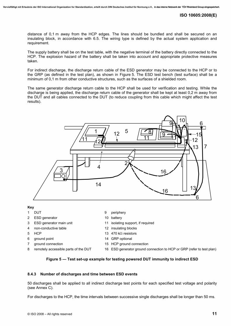
For indirect discharge, the discharge return cable of the ESD generator may be connected to the HCP or to the GRP (as defined in the test plan), as shown in Figure 5. The ESD test bench (test surface) shall be a minimum of 0,1 m from other conductive structures, such as the surfaces of a shielded room.
The same generator discharge return cable to the HCP shall be used for verification and testing. While the discharge is being applied, the discharge return cable of the generator shall be kept at least 0,2 m away from the DUT and all cables connected to the DUT (to reduce coupling from this cable which might affect the test results).
Key 1 DUT 9 periphery 2 ESD generator 10 battery 3 ESD generator main unit 11 isolating support, if required 4 non-conductive table 12 insulating blocks 5 HCP 13 470 kΩ resistors 6 ground point 14 GRP optional 7 ground connection 15 HCP ground connection 8 remotely accessible parts of the DUT 16 ESD generator ground connection to HCP or GRP (refer to test plan)
Figure 5 — Test set-up example for testing powered DUT immunity to indirect ESD
8.4.3 Number of discharges and time between ESD events
50 discharges shall be applied to all indirect discharge test points for each specified test voltage and polarity (see Annex C).
For discharges to the HCP, the time intervals between successive single discharges shall be longer than 50 ms.
Vervielfältigt mit Erlaubnis der ISO International Organization for Standardization, erteilt durch DIN Deutsches Institut für Normung e.V., in das interne Netzwerk der TÜV Rheinland Group eingespeichert.
ISO 10605:2008(E)
12 © ISO 2008 – All rights reserved
8.4.4 Orientation of ESD generator
For discharges to coupling planes (i.e. indirect discharges), the discharge tip is in the same plane as the HCP while making contact with the edge of the plane. No discharge is made to the flat surface of the HCP.
8.4.5 Test voltage
The test voltages (in accordance with Annex C) shall be increased, using at least two values, up to the maximum test level.
NOTE Some products have the tendency to exhibit susceptibility responses when exposed to specific test voltages, but not necessarily at other test voltage levels.
9 Component packaging and handling test method (unpowered test)
9.1 General
The test shall subject the DUT to simulated discharges from humans during the assembly process or in the service case. Testing shall consist of direct application of discharges to the DUT.
Before applying any discharges to the DUT, verify that the ESD generator discharge verification procedure, as specified in Annex A, has been performed within the time period established by the laboratory or the customer.
For the packaging and handling test, the ESD generator shall be configured with the 150 pF capacitor and the resistor value specified in the test plan.
9.2 Test plan
Prior to performing the test, generate a test plan, including the following:
⎯ the detailed test set-up;
⎯ test points;
⎯ electronic module mode of operation;
⎯ any special instructions and changes from the standard test.
9.3 Test procedure
9.3.1 General
The test shall be performed by direct contact discharge on all pins and contacts, and/or air discharge mode on all surfaces and points that can be touched during the assembly process or in the service case.
Apply the ESD at (as a minimum) each connector pin, case, button, switch, display, case screw and case opening of the DUT that is accessible during handling. For this procedure, recessed connector pins are considered accessible during handling.
To access recessed connector pins, an insulated solid wire with a cross-section between 0,5 mm2 and 2 mm2 and a maximum length of 25 mm shall be used.
Discharge on pins of a connector with closely-spaced pins may be difficult. In this case, it is possible to use insulated solid wire with a cross-section between 0,5 mm2 and 2 mm2, and a maximum length of 25 mm, as for recessed pins.
Vervielfältigt mit Erlaubnis der ISO International Organization for Standardization, erteilt durch DIN Deutsches Institut für Normung e.V., in das interne Netzwerk der TÜV Rheinland Group eingespeichert.
ISO 10605:2008(E)
© ISO 2008 – All rights reserved 13
Discharges shall be applied to all specified test points in the test plan. Product response may be affected by the polarity of the discharge. Both polarities of discharge shall be used during testing to determine their effect on the DUT.
9.3.2 Test set-up
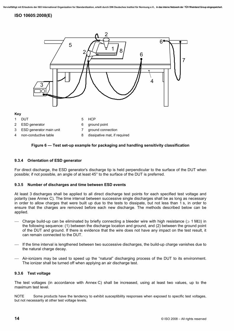
The test set-up for testing of packaging and handling sensitivity is shown in Figure 6. The DUT shall be tested without periphery, as delivered by the supplier.
The safety ground connection (item 7 in Figure 6) may include 2 × 470 kΩ resistors, as for the powered-up tests (see Figures 4 and 5).
If required in the test plan, a static dissipative mat shall be used between DUT and HCP. It shall be ensured that the mat projects beyond the DUT. The surface resistivity of this material shall be between 107 Ω per square and 109 Ω per square.
For direct discharge (contact discharge mode and/or air discharge mode), the discharge return cable of the ESD generator shall be connected to the HCP, as shown in Figure 6.
The ESD test bench (test surface) shall be a minimum of 0,1 m from other conductive structures, such as the surfaces of a shielded room.
The same generator discharge return cable to the HCP shall be used for verification. The discharge return cable of the generator should be positioned at least 0,2 m away from the DUT while the discharge is being applied. The discharge return cable shall also be kept at least 0,2 m away from the DUT.
9.3.3 Electrode connections for direct discharge method
9.3.3.1 Contact discharge mode
In the case of contact discharges, the tip of the discharge electrode (see Figure 1) shall touch a conducting point on the DUT before the discharge switch is actuated.
Where painted surfaces cover a conducting substrate, the following procedure is used. If the coating is not declared to be an insulating coating by the equipment manufacturer, then the pointed tip of the generator penetrates the coating so as to make contact with the conducting substrate.
9.3.3.2 Air discharge mode
In the case of air discharges, the tip of the discharge electrode (see Figure 2) shall be brought sufficiently close to the DUT as quickly as possible after the discharge switch is actuated (see 7.3).
Where painted surfaces cover a conducting substrate or dielectric surfaces are used as boxes, the following procedure is used. If the coating is declared to be an insulating coating for the dielectric surfaces, then the surface is tested as an insulating surface using the air discharge mode.
Vervielfältigt mit Erlaubnis der ISO International Organization for Standardization, erteilt durch DIN Deutsches Institut für Normung e.V., in das interne Netzwerk der TÜV Rheinland Group eingespeichert.
ISO 10605:2008(E)
14 © ISO 2008 – All rights reserved
Key 1 DUT 5 HCP 2 ESD generator 6 ground point 3 ESD generator main unit 7 ground connection 4 non-conductive table 8 dissipative mat, if required
Figure 6 — Test set-up example for packaging and handling sensitivity classification
9.3.4 Orientation of ESD generator
For direct discharge, the ESD generator's discharge tip is held perpendicular to the surface of the DUT when possible; if not possible, an angle of at least 45° to the surface of the DUT is preferred.
9.3.5 Number of discharges and time between ESD events
At least 3 discharges shall be applied to all direct discharge test points for each specified test voltage and polarity (see Annex C). The time interval between successive single discharges shall be as long as necessary in order to allow charges that were built up due to the tests to dissipate, but not less than 1 s, in order to ensure that the charges are removed before each new discharge. The methods described below can be applied.
⎯ Charge build-up can be eliminated by briefly connecting a bleeder wire with high resistance (W 1 MΩ) in the following sequence: (1) between the discharge location and ground, and (2) between the ground point of the DUT and ground. If there is evidence that the wire does not have any impact on the test result, it can remain connected to the DUT.
⎯ If the time interval is lengthened between two successive discharges, the build-up charge vanishes due to the natural charge decay.
⎯ Air-ionizers may be used to speed up the “natural” discharging process of the DUT to its environment. The ionizer shall be turned off when applying an air discharge test.
9.3.6 Test voltage
The test voltages (in accordance with Annex C) shall be increased, using at least two values, up to the maximum test level.
NOTE Some products have the tendency to exhibit susceptibility responses when exposed to specific test voltages, but not necessarily at other test voltage levels.
Vervielfältigt mit Erlaubnis der ISO International Organization for Standardization, erteilt durch DIN Deutsches Institut für Normung e.V., in das interne Netzwerk der TÜV Rheinland Group eingespeichert.

ISO 10605:2008(E)
© ISO 2008 – All rights reserved 15
Once complete testing has been performed, the DUT shall pass complete function testing successfully. There shall be no permanent damage. In addition, the effectiveness of the EMC protective circuits (e.g. input capacitors ensuring electromagnetic interference immunity and emission, respectively) should be tested after ESD exposure, in accordance with Annex C.
10 Vehicle test method
10.1 General
Choose a generator capacitance of 330 pF for areas that can easily be accessed only from the inside of the vehicle and resistance of 330 Ω or 2 kΩ. The maximum test voltage can be limited in this case to 15 kV. Choose a capacitance of 150 pF for points that can easily be touched only from the outside of the vehicle and resistance of 330 Ω or 2 kΩ. In this case, the maximum test voltage is 25 kV. Areas that can be touched both from the outside and inside shall be tested with both generator capacitance values and 15 kV and 25 kV maximum test voltage, respectively.
Before applying any discharges to the DUT, verify that the ESD generator discharge verification procedure, as specified in Annex A, has been performed within the time period established by the laboratory or the customer.
Conductive surfaces shall be tested using contact mode discharges. For contact discharge, use the contact discharge tip (see Figure 1). Air discharge may also be applied to conductive surfaces, if required in the test plan.
Non-conductive surfaces shall be tested using air mode discharges. For air discharge, use the air discharge tip (see Figure 2).
10.2 Test plan
Prior to performing the test, generate a test plan, including the following:
⎯ test points;
⎯ electronic module mode of operation;
⎯ vehicle modes of operation (e.g. drive, idle, cruise);
⎯ any special instructions and changes from the standard test.
10.3 Test procedure
10.3.1 General
Testing shall consist of contact and/or air discharge mode application.
Discharges shall be applied to all specified test points with the equipment operating in normal modes. Product response may be affected by the polarity of the discharge. Both polarities of discharge shall be used during testing to determine their effect on the DUT.
10.3.2 Test set-up
For areas accessible only from the inside of the vehicle, the ESD generator ground connection shall be connected directly to the grounded metallic part of the body (e.g. seat railing, door latch). Figure 7 a) provides an example of test set-up for an internal point.
Vervielfältigt mit Erlaubnis der ISO International Organization for Standardization, erteilt durch DIN Deutsches Institut für Normung e.V., in das interne Netzwerk der TÜV Rheinland Group eingespeichert.

ISO 10605:2008(E)
16 © ISO 2008 – All rights reserved
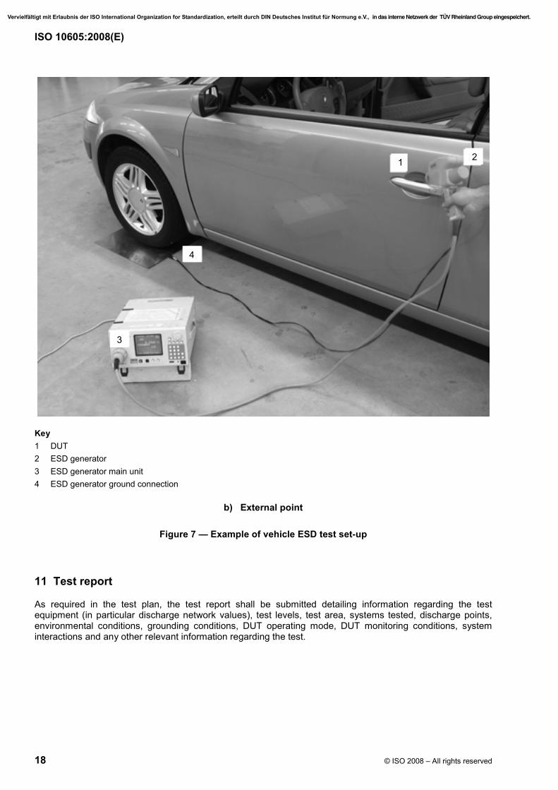
For areas accessible from the outside of the vehicle, the ESD generator ground connection can be connected directly to the nearest metallic part of the body, or directly to a metal plate placed under the wheel closest to the application point (as defined in the test plan). Figure 7 b) provides an example of test set-up for an external point.
In a standard test sequence, the engine of the vehicle shall be running in drive or idle mode. If the test sequence involves tests of systems (e.g. cruise control) at road speeds using a dynamometer, specify the speed in the test plan.
10.3.3 Electrode connections (for direct discharge method)
10.3.3.1 Contact discharge mode
In the case of contact discharges, the tip of the discharge electrode (see Figure 1) shall touch a conducting point on the DUT before the discharge switch is actuated.
Where painted surfaces cover a conducting substrate, the following procedure is used. If the coating is not declared to be an insulating coating by the equipment manufacturer, then the pointed tip of the generator penetrates the coating so as to make contact with the conducting substrate.
10.3.3.2 Air discharge mode
In the case of air discharges, the tip of the discharge electrode (see Figure 2) shall be brought sufficiently close to the DUT as quickly as possible after the discharge switch is actuated (see 7.3).
Where painted surfaces cover a conducting substrate or dielectric surfaces are used as boxes, the following procedure is used. If the coating is declared to be an insulating coating for the dielectric surfaces, then the surface is tested as an insulating surface using the air discharge mode.
10.3.4 Orientation of ESD generator
For direct discharge, the ESD generator's discharge tip is held perpendicular to the surface of the DUT when possible; if not possible, an angle of at least 45° to the surface of the DUT is preferred.
10.3.5 Number of discharges and time between ESD events
At least 3 discharges shall be applied to all direct discharge test points for each specified test voltage and polarity (see Annex C). The time interval between successive single discharges shall be as long as necessary in order to allow charges that were built up due to the tests to dissipate, but not less than 1 s, in order to ensure that the charges are removed before each new discharge. The methods described below can be applied.
⎯ Charge build-up can be eliminated by briefly connecting a bleeder wire with high resistance (W 1 MΩ) in the following sequence: (1) between the discharge location and ground, and (2) between the ground point of the DUT and ground. If there is evidence that the wire does not have any impact on the test result, it can remain connected to the DUT.
⎯ If the time interval is lengthened between two successive discharges, the build-up charge vanishes due to the natural charge decay.
⎯ Air-ionizers may be used to speed up the “natural” discharging process of the DUT to its environment. The ionizer shall be turned off when applying an air discharge test.
Vervielfältigt mit Erlaubnis der ISO International Organization for Standardization, erteilt durch DIN Deutsches Institut für Normung e.V., in das interne Netzwerk der TÜV Rheinland Group eingespeichert.

ISO 10605:2008(E)
© ISO 2008 – All rights reserved 17
10.3.6 Test voltage
The test voltages (in accordance with Annex C) shall be increased, using at least two values, up to the maximum test level.
NOTE Some products have the tendency to exhibit susceptibility responses when exposed to specific test voltages, but not necessarily at other test voltage levels.
10.3.7 Selection of test points
Testing is performed on and in the vehicle by applying air discharges or contact discharge (as described in the test plan) on all areas that can be reached by the person using the vehicle (e.g. tip switches, switches, displays, surfaces, steering lock, controls, antennas).
Key 1 DUT 2 ESD generator 3 ESD generator main unit (can be outside or inside the vehicle) 4 ESD generator ground connection
a) Internal point
Figure 7 (continued)
Vervielfältigt mit Erlaubnis der ISO International Organization for Standardization, erteilt durch DIN Deutsches Institut für Normung e.V., in das interne Netzwerk der TÜV Rheinland Group eingespeichert.
ISO 10605:2008(E)
18 © ISO 2008 – All rights reserved
Key 1 DUT 2 ESD generator 3 ESD generator main unit 4 ESD generator ground connection
b) External point
Figure 7 — Example of vehicle ESD test set-up
11 Test report
As required in the test plan, the test report shall be submitted detailing information regarding the test equipment (in particular discharge network values), test levels, test area, systems tested, discharge points, environmental conditions, grounding conditions, DUT operating mode, DUT monitoring conditions, system interactions and any other relevant information regarding the test.
4
1 2
3
Vervielfältigt mit Erlaubnis der ISO International Organization for Standardization, erteilt durch DIN Deutsches Institut für Normung e.V., in das interne Netzwerk der TÜV Rheinland Group eingespeichert.

ISO 10605:2008(E)
© ISO 2008 – All rights reserved 19
Annex A (normative)
Current target specification and verification of ESD generator
A.1 Current target specification — Input impedance
The current target used to measure the discharge current of ESD generators, measured between the inner electrode and ground, shall have an input impedance at d.c. of no more than 2,1 Ω.
NOTE 1 The target is supposed to measure the ESD current into a perfect ground plane. To minimize error caused by the difference between a perfectly conducting plane and the input impedance of the target, a 2,1 Ω limit is set for the input impedance. However, if the input impedance of the target is too low, the output signal will be very small, which can cause errors due to coupling into the cables and the oscilloscope. Furthermore, if a much lower resistance value is taken, parasitic inductance becomes more severe.
NOTE 2 Annex B provides a description of an example for the current target.
A.2 Verification of ESD generator
A.2.1 General
Correlation of the results of an ESD evaluation is extremely important, particularly when tests are to be conducted using ESD generators from different manufacturers, or when testing is expected to extend over a long period of time. It is essential that repeatability be a driving factor in the evaluation. The ESD generator shall be verified in defined time periods in accordance with a recognised quality assurance system.
The ESD generators shall meet all specifications at any specified repetition rate used for compliance testing.
A.2.2 Test equipment required for ESD generator verification
The following equipment is required for calibrating ESD generators:
⎯ oscilloscope with at least 1 GHz analogue bandwidth;
⎯ current target;
⎯ high-voltage meter capable of measuring voltages of at least 25 kV with at least 5 % accuracy; it may be necessary to use an electrostatic voltmeter to avoid loading the output voltage;
⎯ reference plane at least 1,2 m × 1,2 m, with the coaxial current target mounted such that there is a distance of at least 0,6 m from the target to any edge of the plane;
⎯ attenuator(s), as required.
A.2.3 Procedure for contact mode generator verification
A.2.3.1 Prior to verifying the discharge current, the amplitude of the ESD generator's test voltage should be determined using a high-voltage meter. The accuracy of the test voltage measurement shall be as specified in Table A.1.
Vervielfältigt mit Erlaubnis der ISO International Organization for Standardization, erteilt durch DIN Deutsches Institut für Normung e.V., in das interne Netzwerk der TÜV Rheinland Group eingespeichert.
ISO 10605:2008(E)
20 © ISO 2008 – All rights reserved
A.2.3.2 The following environmental conditions at the time verification is performed shall be recorded:
⎯ temperature;
⎯ relative humidity.
These conditions should be within the limits specified in Clause 4.
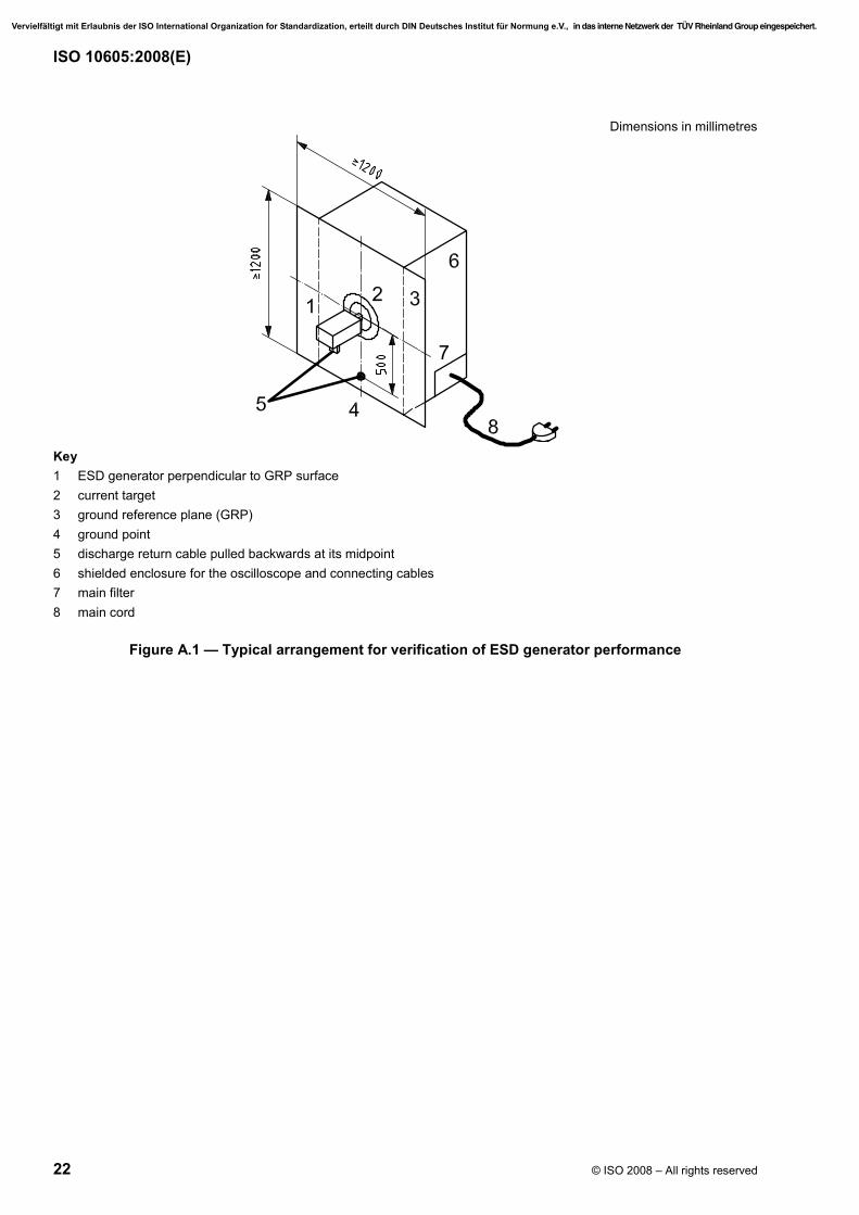
A.2.3.3 The current target shall be mounted at the centre of the vertical verification plane of at least 1,2 m × 1,2 m (see Figure A.1). The connection for the ESD generator discharge return cable to the verification plane shall be made directly below the target, at a distance of 0,5 m below the target. The discharge return cable shall be pulled backwards at the middle of the cable, forming an isosceles triangle. The discharge return cable shall not lie on the floor during verification.
A.2.3.4 The following parameters shall be measured, or obtained from measured values, in order to verify whether the current waveform of an ESD generator is within specifications:
⎯ Ip, the peak value of the discharge current, in A,
⎯ I1, the value of the current at t1, in A (from Table 2),
⎯ I2, the value of the current at t2, in A (from Table 2),
⎯ tr, the rise time of the current, in ns.
The average value of a parameter Xx is indicated by x.X
EXAMPLE pI signifies the average of the peak current values.
A.2.3.5 The shielded enclosure, with a vertical ground reference plane of at least 1,2 m × 1,2 m in which the target is mounted in order to shield the oscilloscope used, may not be necessary if it can be proven by measurement that indirect coupling paths onto the measurement system will not influence the verification results. When the oscilloscope is set to a trigger level that is u 10 % compared to the resulting peak output voltage from the first peak current, and the ESD generator is discharged to the outer ring of the target (instead of to the inner ring) and no triggering of the oscilloscope results, then the verification system can be declared sufficiently immune and no shielded enclosure is needed.
Vervielfältigt mit Erlaubnis der ISO International Organization for Standardization, erteilt durch DIN Deutsches Institut für Normung e.V., in das interne Netzwerk der TÜV Rheinland Group eingespeichert.
ISO 10605:2008(E)
© ISO 2008 – All rights reserved 21
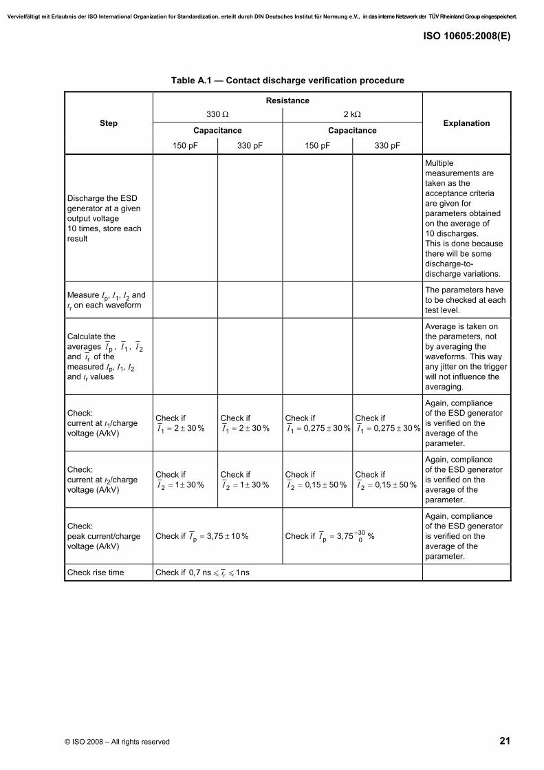
Table A.1 — Contact discharge verification procedure
Resistance 330 Ω 2 kΩ
Step Capacitance Capacitance
Explanation
150 pF 330 pF 150 pF 330 pF
Discharge the ESD generator at a given output voltage 10 times, store each result
Multiple measurements are taken as the acceptance criteria are given for parameters obtained on the average of 10 discharges. This is done because there will be some discharge-to-discharge variations.
Measure Ip, I1, I2 and tr on each waveform
The parameters have to be checked at each test level.
Calculate the averages pI , 1I , 2I and rt of the measured Ip, I1, I2 and tr values
Average is taken on the parameters, not by averaging the waveforms. This way any jitter on the trigger will not influence the averaging.
Check: current at t1/charge voltage (A/kV)
Check if 1 2 30 %I = ±
Check if 1 2 30 %I = ±
Check if 1 0,275 30%I = ±
Check if 1 0,275 30%I = ±
Again, compliance of the ESD generator is verified on the average of the parameter.
Check: current at t2/charge voltage (A/kV)
Check if 2 1 30 %I = ±
Check if 2 1 30 %I = ±
Check if 2 0,15 50 %I = ±
Check if 2 0,15 50 %I = ±
Again, compliance of the ESD generator is verified on the average of the parameter.
Check: peak current/charge voltage (A/kV)
Check if p 3,75 10%I = ± Check if 30p 03,75I += %
Again, compliance of the ESD generator is verified on the average of the parameter.
Check rise time Check if r0,7 ns 1nstu u
Vervielfältigt mit Erlaubnis der ISO International Organization for Standardization, erteilt durch DIN Deutsches Institut für Normung e.V., in das interne Netzwerk der TÜV Rheinland Group eingespeichert.
ISO 10605:2008(E)
22 © ISO 2008 – All rights reserved
Dimensions in millimetres
Key 1 ESD generator perpendicular to GRP surface 2 current target 3 ground reference plane (GRP) 4 ground point 5 discharge return cable pulled backwards at its midpoint 6 shielded enclosure for the oscilloscope and connecting cables 7 main filter 8 main cord
Figure A.1 — Typical arrangement for verification of ESD generator performance
Vervielfältigt mit Erlaubnis der ISO International Organization for Standardization, erteilt durch DIN Deutsches Institut für Normung e.V., in das interne Netzwerk der TÜV Rheinland Group eingespeichert.
ISO 10605:2008(E)
© ISO 2008 – All rights reserved 23
Annex B (informative)
Standard target drawings and target verification method
B.1 Standard target description
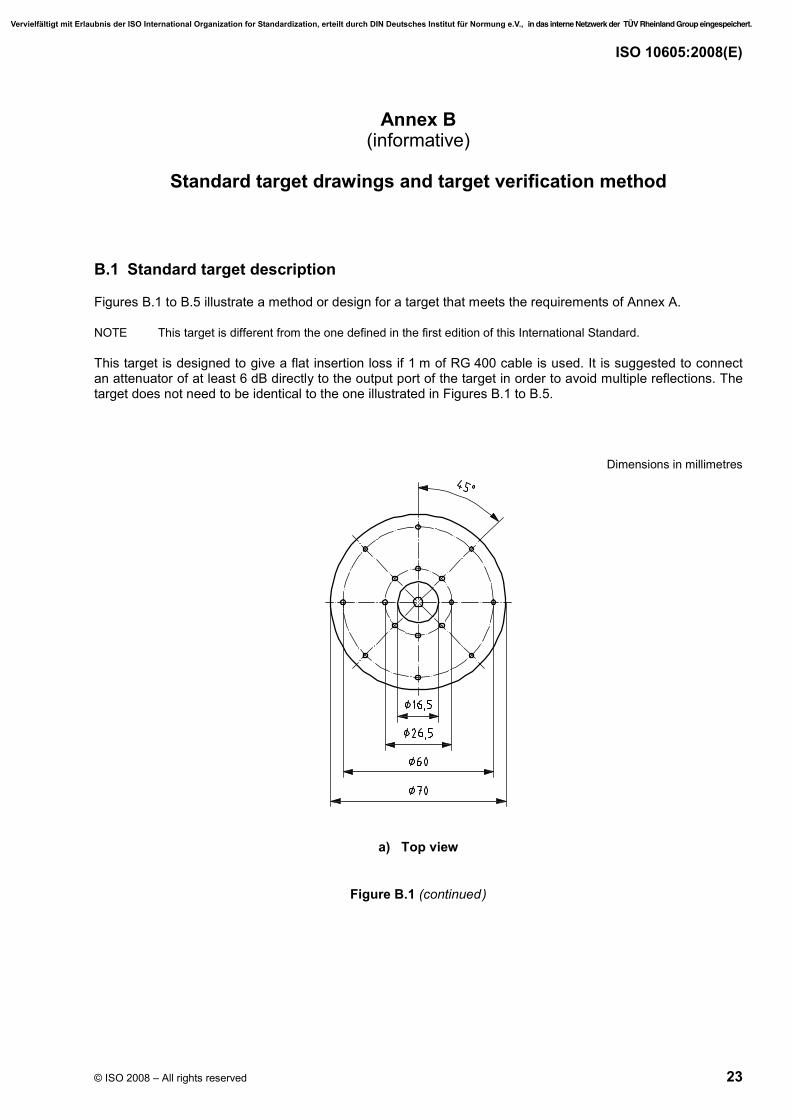
Figures B.1 to B.5 illustrate a method or design for a target that meets the requirements of Annex A.
NOTE This target is different from the one defined in the first edition of this International Standard.
This target is designed to give a flat insertion loss if 1 m of RG 400 cable is used. It is suggested to connect an attenuator of at least 6 dB directly to the output port of the target in order to avoid multiple reflections. The target does not need to be identical to the one illustrated in Figures B.1 to B.5.
Dimensions in millimetres
a) Top view
Figure B.1 (continued)
Vervielfältigt mit Erlaubnis der ISO International Organization for Standardization, erteilt durch DIN Deutsches Institut für Normung e.V., in das interne Netzwerk der TÜV Rheinland Group eingespeichert.
ISO 10605:2008(E)
24 © ISO 2008 – All rights reserved
Dimensions in millimetres
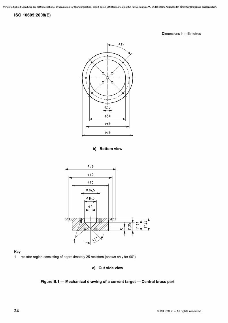
b) Bottom view
Key 1 resistor region consisting of approximately 25 resistors (shown only for 90°)
c) Cut side view
Figure B.1 — Mechanical drawing of a current target — Central brass part
Vervielfältigt mit Erlaubnis der ISO International Organization for Standardization, erteilt durch DIN Deutsches Institut für Normung e.V., in das interne Netzwerk der TÜV Rheinland Group eingespeichert.
ISO 10605:2008(E)
© ISO 2008 – All rights reserved 25
Dimensions in millimetres
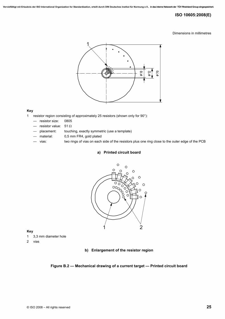
Key 1 resistor region consisting of approximately 25 resistors (shown only for 90°):
— resistor size: 0805 — resistor value: 51 Ω — placement: touching, exactly symmetric (use a template) — material: 0,5 mm FR4, gold plated — vias: two rings of vias on each side of the resistors plus one ring close to the outer edge of the PCB
a) Printed circuit board
Key 1 3,3 mm diameter hole 2 vias
b) Enlargement of the resistor region
Figure B.2 — Mechanical drawing of a current target — Printed circuit board
Vervielfältigt mit Erlaubnis der ISO International Organization for Standardization, erteilt durch DIN Deutsches Institut für Normung e.V., in das interne Netzwerk der TÜV Rheinland Group eingespeichert.
ISO 10605:2008(E)
26 © ISO 2008 – All rights reserved
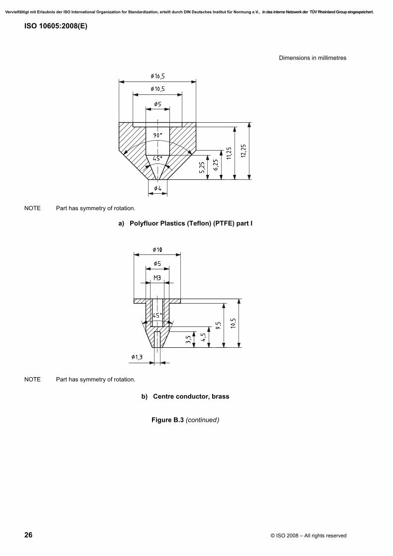
Dimensions in millimetres
NOTE Part has symmetry of rotation.
a) Polyfluor Plastics (Teflon) (PTFE) part I
NOTE Part has symmetry of rotation.
b) Centre conductor, brass
Figure B.3 (continued)
Vervielfältigt mit Erlaubnis der ISO International Organization for Standardization, erteilt durch DIN Deutsches Institut für Normung e.V., in das interne Netzwerk der TÜV Rheinland Group eingespeichert.
ISO 10605:2008(E)
© ISO 2008 – All rights reserved 27
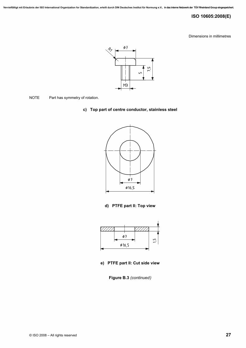
Dimensions in millimetres
NOTE Part has symmetry of rotation.
c) Top part of centre conductor, stainless steel
d) PTFE part II: Top view
e) PTFE part II: Cut side view
Figure B.3 (continued)
Vervielfältigt mit Erlaubnis der ISO International Organization for Standardization, erteilt durch DIN Deutsches Institut für Normung e.V., in das interne Netzwerk der TÜV Rheinland Group eingespeichert.
ISO 10605:2008(E)
28 © ISO 2008 – All rights reserved
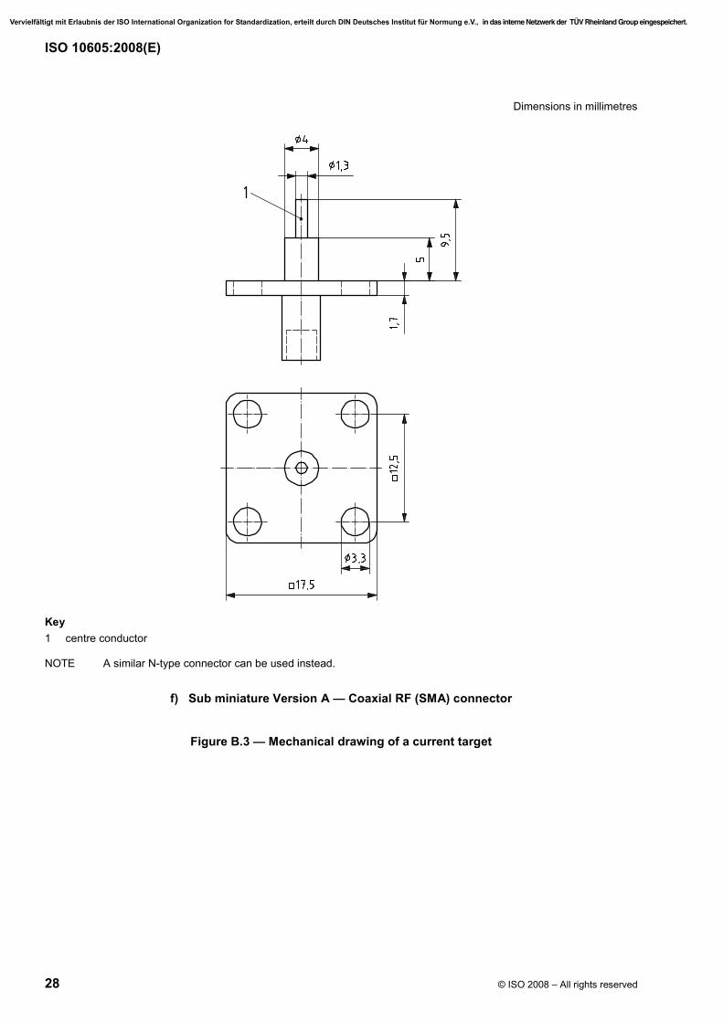
Dimensions in millimetres
Key 1 centre conductor
NOTE A similar N-type connector can be used instead.
f) Sub miniature Version A — Coaxial RF (SMA) connector
Figure B.3 — Mechanical drawing of a current target
Vervielfältigt mit Erlaubnis der ISO International Organization for Standardization, erteilt durch DIN Deutsches Institut für Normung e.V., in das interne Netzwerk der TÜV Rheinland Group eingespeichert.
ISO 10605:2008(E)
© ISO 2008 – All rights reserved 29
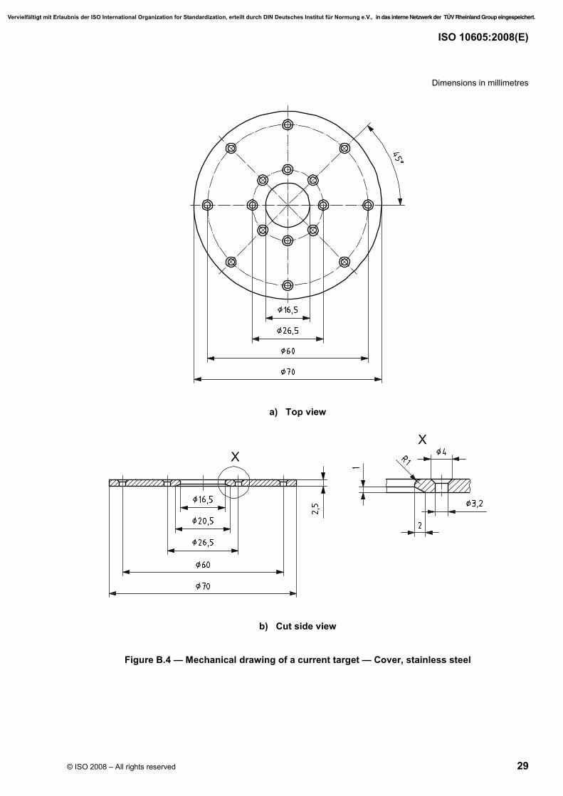
Dimensions in millimetres
a) Top view
b) Cut side view
Figure B.4 — Mechanical drawing of a current target — Cover, stainless steel
Vervielfältigt mit Erlaubnis der ISO International Organization for Standardization, erteilt durch DIN Deutsches Institut für Normung e.V., in das interne Netzwerk der TÜV Rheinland Group eingespeichert.
ISO 10605:2008(E)
30 © ISO 2008 – All rights reserved
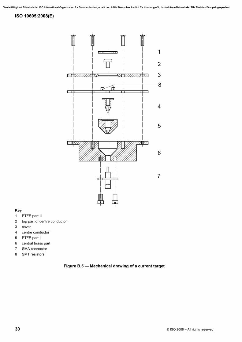
Key 1 PTFE part II 2 top part of centre conductor 3 cover 4 centre conductor 5 PTFE part I 6 central brass part 7 SMA connector 8 SMT resistors
Figure B.5 — Mechanical drawing of a current target
Vervielfältigt mit Erlaubnis der ISO International Organization for Standardization, erteilt durch DIN Deutsches Institut für Normung e.V., in das interne Netzwerk der TÜV Rheinland Group eingespeichert.
ISO 10605:2008(E)
© ISO 2008 – All rights reserved 31
B.2 Current target specification
B.2.1 Current target specification — Insertion loss
Instead of specifying the insertion loss of the current target, the insertion loss of the measurement chain consisting of the target, attenuator and cable is specified. This simplifies the measurement system characterization, as only this chain and the oscilloscope need to be characterized, instead of each element individually.
The variation of the insertion loss of the target-attenuator-cable chain shall be less than ± 0,5 dB between d.c. and 1 GHz.
NOTE 1 If the variation limits of the insertion loss are exceeded, then by means of complex Fast Fourier transform (FFT) and inverse FFT, this response can be compensated for. However, this is not recommended.
NOTE 2 Different verification time intervals can be used for the d.c. transfer impedance and the more involved insertion loss measurements. If a repeated d.c. transfer impedance measurement shows a result which differs from the original measurement by less than 1 %, the user can assume the insertion loss of the target-attenuator-cable chain has not changed, providing the same cable and attenuator are used and no other indications (e.g. loose or damaged connectors) indicate otherwise.
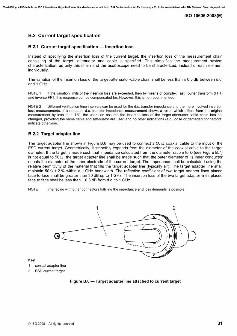
B.2.2 Target adapter line
The target adapter line shown in Figure B.6 may be used to connect a 50 Ω coaxial cable to the input of the ESD current target. Geometrically, it smoothly expands from the diameter of the coaxial cable to the target diameter. If the target is made such that impedance calculated from the diameter ratio d to D (see Figure B.7) is not equal to 50 Ω, the target adapter line shall be made such that the outer diameter of its inner conductor equals the diameter of the inner electrode of the current target. The impedance shall be calculated using the relative permittivity of the material that fills the target adapter line (typically air). The target adapter line shall maintain 50 Ω ± 2 % within a 1 GHz bandwidth. The reflection coefficient of two target adapter lines placed face-to-face shall be greater than 30 dB up to 1 GHz. The insertion loss of the two target adapter lines placed face to face shall be less than ± 0,3 dB from d.c. to 1 GHz.
NOTE Interfacing with other connectors fulfilling the impedance and loss demands is possible.
Key 1 conical adapter line 2 ESD current target
Figure B.6 — Target adapter line attached to current target
Vervielfältigt mit Erlaubnis der ISO International Organization for Standardization, erteilt durch DIN Deutsches Institut für Normung e.V., in das interne Netzwerk der TÜV Rheinland Group eingespeichert.
ISO 10605:2008(E)
32 © ISO 2008 – All rights reserved
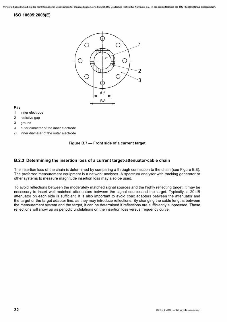
Key 1 inner electrode 2 resistive gap 3 ground d outer diameter of the inner electrode D inner diameter of the outer electrode
Figure B.7 — Front side of a current target
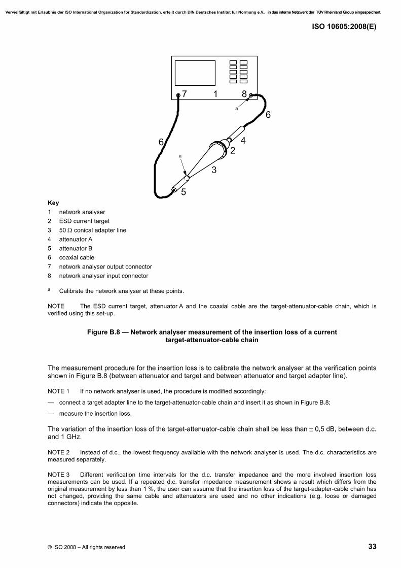
B.2.3 Determining the insertion loss of a current target-attenuator-cable chain
The insertion loss of the chain is determined by comparing a through connection to the chain (see Figure B.8). The preferred measurement equipment is a network analyser. A spectrum analyser with tracking generator or other systems to measure magnitude insertion loss may also be used.
To avoid reflections between the moderately matched signal sources and the highly reflecting target, it may be necessary to insert well-matched attenuators between the signal source and the target. Typically, a 20 dB attenuator on each side is sufficient. It is also important to avoid coax adapters between the attenuator and the target or the target adapter line, as they may introduce reflections. By changing the cable lengths between the measurement system and the target, it can be determined if reflections are sufficiently suppressed. Those reflections will show up as periodic undulations on the insertion loss versus frequency curve.
Vervielfältigt mit Erlaubnis der ISO International Organization for Standardization, erteilt durch DIN Deutsches Institut für Normung e.V., in das interne Netzwerk der TÜV Rheinland Group eingespeichert.
ISO 10605:2008(E)
© ISO 2008 – All rights reserved 33
Key 1 network analyser 2 ESD current target 3 50 Ω conical adapter line 4 attenuator A 5 attenuator B 6 coaxial cable 7 network analyser output connector 8 network analyser input connector
a Calibrate the network analyser at these points.
NOTE The ESD current target, attenuator A and the coaxial cable are the target-attenuator-cable chain, which is verified using this set-up.
Figure B.8 — Network analyser measurement of the insertion loss of a current target-attenuator-cable chain
The measurement procedure for the insertion loss is to calibrate the network analyser at the verification points shown in Figure B.8 (between attenuator and target and between attenuator and target adapter line).
NOTE 1 If no network analyser is used, the procedure is modified accordingly:
— connect a target adapter line to the target-attenuator-cable chain and insert it as shown in Figure B.8;
— measure the insertion loss.
The variation of the insertion loss of the target-attenuator-cable chain shall be less than ± 0,5 dB, between d.c. and 1 GHz.
NOTE 2 Instead of d.c., the lowest frequency available with the network analyser is used. The d.c. characteristics are measured separately.
NOTE 3 Different verification time intervals for the d.c. transfer impedance and the more involved insertion loss measurements can be used. If a repeated d.c. transfer impedance measurement shows a result which differs from the original measurement by less than 1 %, the user can assume that the insertion loss of the target-adapter-cable chain has not changed, providing the same cable and attenuators are used and no other indications (e.g. loose or damaged connectors) indicate the opposite.
Vervielfältigt mit Erlaubnis der ISO International Organization for Standardization, erteilt durch DIN Deutsches Institut für Normung e.V., in das interne Netzwerk der TÜV Rheinland Group eingespeichert.

ISO 10605:2008(E)
34 © ISO 2008 – All rights reserved
B.2.4 Determining the d.c. transfer resistance of a target-attenuator-cable chain
The d.c. transfer resistance of a target-attenuator-cable chain is defined as the ratio between the current injected to the input of the target and the voltage across a precision 50 Ω load at the output of the cable (i.e. placed at the end of the cable instead of the oscilloscope). The circuit diagram is illustrated in Figure B.9.
In an ESD measurement, an oscilloscope displays a voltage Vosc if a current Isys is injected into the target. To calculate the unknown current from the displayed voltage, the voltage is divided by a d.c. system transfer resistance Zsys.
Key 1 target 2 example of internal circuit of a current target (other circuits are possible) 3 attenuator 4 internal circuit of an attenuator 5 d.c. current source 6 ammeter 7 50 Ω load 8 digital voltmeter (DVM)
Figure B.9 — Circuit diagram to determine the d.c. system transfer resistance
The d.c. system transfer resistance of the target-attenuator-cable chain can be determined by the method below.
⎯ Inject a current Isys of approximately 1 A into the front side of the current target. The front side is the side to which discharges are made. The current shall be known within ± 1 %. Larger currents may be used if they do not thermally stress the target beyond its specifications. Measure the output voltage V across the precision 50 Ω load.
⎯ Calculate the transfer impedance according to Equation (B.1):
syssys
VZI
= (B.1)
NOTE To verify that thermal voltages do not influence the result, the measurement can be done with positive and negative current. A check is made that the two results are within 0,5 % of each other.
Other methods to determine the transfer characteristics of the whole target-attenuator-cable chain may be used.
Vervielfältigt mit Erlaubnis der ISO International Organization for Standardization, erteilt durch DIN Deutsches Institut für Normung e.V., in das interne Netzwerk der TÜV Rheinland Group eingespeichert.

ISO 10605:2008(E)
© ISO 2008 – All rights reserved 35
Annex C (informative)
Function performance status classification (FPSC)
C.1 General
This annex provides a general method for defining the acceptable performance of electrical/electronic functions of automotive electrical systems during and after ESD immunity testing. This method is based on the following considerations:
a) a DUT/vehicle can include one or several functions (e.g. an electronic unit can manage front wiping, courtesy lighting and low beam lighting);
b) a function can have one or several operating modes (e.g. low beam ON, low beam OFF, courtesy lighting ON, courtesy lighting OFF);
c) an operating mode can have several statuses (I, II, III, IV) (e.g. in low beam ON operating mode, the status II can be associated to low beam OFF during disturbance application with automatic recovery of low beam after disturbance suppression).
The functional performance status classification is applicable to each function.
C.2 FPSC approach
The approach is based on the following principles:
a) functional performance status classification is applicable to each individual function; hence, a vehicle will have many functions and a DUT is likely to include several functions (e.g. an electronic unit can manage front wiping, courtesy lighting and low beam lighting);
b) a function can be a simple on-off operation or it can be complex, like data communication on a data bus.
It has to be emphasized that, as described in this International Standard, components or systems shall only be tested under the conditions that represent the simulated automotive electromagnetic environments to which the devices would actually be subjected. This will help to ensure a technically and economically optimized design for potentially susceptible components and systems.
It should also be noted that this annex is not intended to be a product specification and cannot function as one. It should be used in conjunction with a specific test procedure in this International Standard. Therefore, no specific values for the test signal severity level are included in this annex since they should be determined by the vehicle manufacturers and component suppliers. Nevertheless, using the concepts described in this annex and by careful application and agreement between manufacturer and supplier, this annex can be used to describe the functional status requirements for a specific device. This can then, in fact, be a statement of how a particular device can be expected to perform under the influence of the specified test signals.
C.3 Essential elements of FPSC
C.3.1 General
There are two elements, outlined in C.3.2 and C.3.3, required to describe an FPSC.
Vervielfältigt mit Erlaubnis der ISO International Organization for Standardization, erteilt durch DIN Deutsches Institut für Normung e.V., in das interne Netzwerk der TÜV Rheinland Group eingespeichert.

ISO 10605:2008(E)
36 © ISO 2008 – All rights reserved
C.3.2 Function performance status
This element defines the expected performance objectives for the function of the DUT subjected to the test conditions. The four function performance statuses of the function (expected behaviour of the function observed during testing) are listed below.
NOTE 1 This element is applicable to every single individual function of a DUT and describes the operational status of the defined function during and after a test.
NOTE 2 The minimum functional status is given in each test. An additional test requirement can be agreed between supplier and vehicle manufacturer.
a) Status I: The function performs as designed, during and after the test.
b) Status II: The function does not perform as designed during the test, but returns automatically to normal operation after the test.
c) Status III: The function does not perform as designed during the test and does not return to normal operation without a simple driver/passenger intervention, such as turning off/on the DUT, or cycling the ignition switch after the disturbance is removed.
d) Status IV: The function does not perform as designed during or after the test and cannot be returned to proper operation without more extensive intervention, such as disconnecting and reconnecting the battery or power feed. The function shall not have sustained any permanent damage as a result of the testing.
C.3.3 Test signal severity level
This element defines the specification of test signal severity level (test severity level) of essential signal parameters. The test signal severity level is the stress level applied to the DUT for any given test method. The test signal severity levels should be determined by the vehicle manufacturer and supplier depending on the required operational characteristics of the function.
C.4 FPSC approach example
C.4.1 General example of FPSC application
Figure C.1 demonstrates the relationship between the test signal severity levels and their corresponding function performance status classification.
Comments listed in Figure C.1 can be interpreted as follows:
a) the function should be nominal event No. 1 (Status I) up to severity level L1;
b) unexpected event No. 2 is allowed above test severity level L1;
c) unexpected event No. 3 is allowed above test severity level L2.
Users may group functions into categories to allow the use of different test levels.
Vervielfältigt mit Erlaubnis der ISO International Organization for Standardization, erteilt durch DIN Deutsches Institut für Normung e.V., in das interne Netzwerk der TÜV Rheinland Group eingespeichert.

ISO 10605:2008(E)
© ISO 2008 – All rights reserved 37
Function performance status
Unexpected event No. 4 (Status IV type, Status I,
II and III allowed)
Unexpected event No. 3 (Status III type, Status I
and II allowed)
Unexpected event No. 2 (Status II type, Status I
allowed)
Nominal function – event No. 1
(Status I type)
Test severity levels
................................. L4i
................................. L3i
................................. L2i
................................. L1i
Figure C.1 — Illustration of function performance status classification
C.4.2 Suggested test severity levels
Tables C.1 to C.7 provide examples of test severity levels.
Table C.1 — Component test — Example severity levels for direct contact discharge
Test severity level Category 1 Category 2 Category 3
L4i ± 8 kV ± 8 kV ± 15 kV
L3i ± 6 kV ± 8 kV ± 8 kV
L2i ± 4 kV ± 4 kV ± 6 kV
L1i ± 2 kV ± 2 kV ± 4 kV
Table C.2 — Component test — Example severity levels for direct air discharge
Test severity level Category 1 Category 2 Category 3
L4i ± 15 kV ± 15 kV ± 25 kV
L3i ± 8 kV ± 8 kV ± 15 kV
L2i ± 4 kV ± 6 kV ± 8 kV
L1i ± 2 kV ± 4 kV ± 6 kV
Table C.3 — Component test — Example severity levels for indirect contact discharge
Test severity level Category 1 Category 2 Category 3
L4i ± 8 kV ± 15 kV ± 20 kV
L3i ± 6 kV ± 8 kV ± 15 kV
L2i ± 4 kV ± 4 kV ± 8 kV
L1i ± 2 kV ± 2 kV ± 4 kV
Vervielfältigt mit Erlaubnis der ISO International Organization for Standardization, erteilt durch DIN Deutsches Institut für Normung e.V., in das interne Netzwerk der TÜV Rheinland Group eingespeichert.

ISO 10605:2008(E)
38 © ISO 2008 – All rights reserved
Table C.4 — Vehicle test — Example severity levels for contact discharge (test points accessible only from inside vehicle)
Test severity level Category 1 Category 2 Category 3
L4i ± 6 kV ± 8 kV ± 8 kV
L3i ± 4 kV ± 4 kV ± 6 kV
L2i ± 2 kV ± 2 kV ± 2 kV
L1i not applicable not applicable not applicable
Table C.5 — Vehicle test — Example severity levels for air discharge (test points accessible only from inside vehicle)
Test severity level Category 1 Category 2 Category 3
L4i ± 8 kV ± 15 kV ± 15 kV
L3i ± 6 kV ± 8 kV ± 8 kV
L2i ± 4 kV ± 4 kV ± 6 kV
L1i ± 2 kV ± 2 kV ± 4 kV
Table C.6 — Vehicle test — Example severity levels for contact discharge (test points accessible only from outside vehicle)
Test severity level Category 1 Category 2 Category 3
L4i ± 6 kV ± 8 kV ± 8 kV
L3i ± 4 kV ± 6 kV ± 6 kV
L2i ± 2 kV ± 2 kV ± 4 kV
L1i not applicable not applicable ± 2 kV
Table C.7 — Vehicle test — Example severity levels for air discharge (test points accessible only from outside vehicle)
Test severity level Category 1 Category 2 Category 3
L4i ± 15 kV ± 15 kV ± 25 kV
L3i ± 8 kV ± 8 kV ± 15 kV
L2i ± 4 kV ± 6 kV ± 8 kV
L1i ± 2 kV ± 4 kV ± 6 kV
Vervielfältigt mit Erlaubnis der ISO International Organization for Standardization, erteilt durch DIN Deutsches Institut für Normung e.V., in das interne Netzwerk der TÜV Rheinland Group eingespeichert.

ISO 10605:2008(E)
© ISO 2008 – All rights reserved 39
Annex D (informative)
Test method guidance — Generator resistor value and air
or contact discharge
D.1 Resistor value selection
Testing with 2 kΩ resistor represents the discharge of a human body directly through the skin. Testing with 330 Ω resistor represents the discharge of a human body through a metallic part (e.g. tool, key, ring). A test with a 330 Ω resistor is more severe than testing with 2 kΩ.
Selection of the discharge resistance to be used for the test should be specified in the test plan.
D.2 Test method selection
The particular test method (air or contact) selected as appropriate for DUT evaluation should be determined by first establishing an intended result for the information that will be gained from the ESD test. Clauses D.3 to D.5 provide an overview of the two approaches, in conjunction with the advantages and disadvantages of each approach.
D.3 Air discharge
D.3.1 General
The air discharge method virtually replicates ESD, as it would occur in the actual environment. In effect, this means that the impulse current waveforms delivered to the DUT are allowed (and expected) to vary significantly from pulse to pulse.
D.3.2 Air discharge advantages
The main benefit is that any insulating surfaces or air gaps in the DUT that prevent ESD can be evaluated for breakdown voltage. Another advantage of the air discharge method is that DUT responses will be caused by phenomena that are similar to actual ESD events. This means that for a given test voltage, one ESD pulse may cause a DUT response, while another pulse may not. When the DUT does respond, the response may be different from discharge to discharge. Finally, air discharge simulates the non-linear relationship between amplitudes of voltage and current found in natural ESD.
D.3.3 Air discharge disadvantages
The major disadvantage to the air discharge ESD method is that, in practice, performance of the method may result in a tedious test series. The air discharge test may require several hours of test time because of the need to apply (possibly) hundreds of ESD pulses to a DUT in order to fully (adequately) evaluate and understand the responses of the DUT and their probabilities of occurrence. Apart from the disadvantage of test time, the DUT may respond inconsistently to the ESD excitations. This produces serious repeatability problems in the test results, requiring further ESD tests to ultimately determine the performance profile of the DUT.
Vervielfältigt mit Erlaubnis der ISO International Organization for Standardization, erteilt durch DIN Deutsches Institut für Normung e.V., in das interne Netzwerk der TÜV Rheinland Group eingespeichert.
ISO 10605:2008(E)
40 © ISO 2008 – All rights reserved
D.4 Contact discharge
D.4.1 General
The contact discharge method simulates ESD, but it does not replicate all of the characteristics of the actual ESD phenomena. The contact discharge method provides a more repeatable ESD test simulation. In effect, this means that the impulse current waveforms delivered to the DUT will remain relatively consistent from pulse to pulse.
The variability associated with the air gap at the time of discharge will generally be avoided and will not depend on the characteristics of the DUT surfaces, provided that the DUT surfaces are not fully non-conductive in construction.
D.4.2 Contact discharge advantages
The major advantage of the contact discharge method is that the consistency and repeatability of the ESD test waveforms usually result in a more consistent and repeatable DUT performance. The contact discharge test method is less tedious than the air discharge method, since it can be performed in a more automated manner, with the impulses applied to the DUT at a relatively fast pulse repetition rate (if it is guaranteed that the charge built up in the meantime between two discharges can vanish). In practice, the use of the contact discharge method permits the evaluation of DUT susceptibility to ESD to be made in a manner that significantly conserves test time.
D.4.3 Contact discharge disadvantages
The major disadvantage of the contact discharge method is that it requires a surface conductivity at the point of test application. In addition, contact discharge testing may not provide an estimate of DUT response to actual-use voltages, since the random variations in the ESD waveform that exist in nature are not reproduced. Finally, the ESD voltage and current become directly proportional during these tests, whereas the relationship between voltage and current in naturally occurring ESD is non-linear.
D.5 DUT surfaces
D.5.1 General
The choice of test method may be made partly on the basis of whether the surfaces of the DUT are conductive or non-conductive.
D.5.2 Conductive surfaces
Conductive surfaces and coupling planes may be subjected to either the air or the contact discharge test method.
Due to better reproducibility, contact mode discharge should be used for conductive surfaces.
D.5.3 Non-conductive surfaces
For insulating surfaces, the air discharge method (by its inherent nature) is predominantly used. The air discharge method is also useful in determining the breakdown voltages of surfaces that have a conducting substrate (subsurface), with an insulating surface layer. If the contact discharge method is used in this latter situation by penetrating the insulating surface layer, it may result in excess current being applied to the DUT, compared to the current in air discharge, since the arc path impedance will be missing. For fully insulating surfaces, the contact discharge test method may be used, but it will be an indirect test that is performed by applying the contact ESD to a conductive plane that is adjacent to the non-conductive surface under evaluation.
Vervielfältigt mit Erlaubnis der ISO International Organization for Standardization, erteilt durch DIN Deutsches Institut für Normung e.V., in das interne Netzwerk der TÜV Rheinland Group eingespeichert.

ISO 10605:2008(E)
© ISO 2008 – All rights reserved 41
D.5.4 Indirect ESD tests
When performing indirect ESD testing, either the air or the contact method may be used, depending on the compatibility of the test method with the goals established for the simulation, as explained in Clauses D.3 and D.4. For this International Standard, only contact mode discharges are used for indirect ESD testing. The reason for this is that contact discharges are more reproducible and require less time between discharges.
Vervielfältigt mit Erlaubnis der ISO International Organization for Standardization, erteilt durch DIN Deutsches Institut für Normung e.V., in das interne Netzwerk der TÜV Rheinland Group eingespeichert.
ISO 10605:2008(E)
42 © ISO 2008 – All rights reserved
Annex E (informative)
Rationale for air discharge generator verification
E.1 It is possible to characterize the approximate behaviour of the generator in air discharge verification. Achieving results that are predictable and repeatable is subject to the same conditions of an air discharge ESD test, as explained in Clause D.3. One major problem is the approach speed of the charged generator electrode towards the uncharged verification target. Even with all other critical parameters (i.e. humidity, temperature and approach speed) held constant, the stochastic nature of the statistical time lag may create large changes in the rise time and peak current. Specifying large tolerances on the measured current, as was done in ANSI C63.16, is objectionable to many people. In air discharge, the current will always be determined by
a) the time-dependent arc resistance, and
b) the electrical and mechanical design of the generator.
As the breakdown physics are independent of the generator design, there is no need to verify them. This gives two options for handling the time-dependent arc resistance:
⎯ choose the discharge parameters (voltage, approach speed, humidity, etc.) and the measurement parameters (time domain, frequency domain, bandwidth, etc.) such that the remaining influence of the arc is so small that it can be neglected (i.e. it approaches an ideal switch); or
⎯ choose the parameters such that the arc influences the discharge current in a known manner.
In both cases, it is possible to investigate the electrical and mechanical design of the generator.
E.2 There are many methods for characterizing the generator design having limited or at least known influence of the arc. Three methods are discussed below.
a) The generator can be held against a large ground plane in air discharge mode and its feed point impedance can be measured, e.g. by using a network analyser. Once the feed point impedance has been obtained, it can be transformed into the time domain to obtain the impulse response. By integration of the impulse response, the step response is obtained. The step response will equal the discharge current at zero Ω arc resistance. As the rise time approaches zero for an ideally switching arc, no useful current rise time can be obtained this way.
b) If the test voltage is low enough (e.g. 500 V) at fast approach speeds, the arc behaviour approaches that of an ideal switch as seen within a 1,5 GHz bandwidth. If the generator is discharged against the target at such a low test voltage, the displayed waveform will be determined by the measurement system (rise time and also the peak value somewhat) and the generator design. Using this method, one would typically discharge the generator at 500 V against the target at fast approach speeds a couple of times and select the waveform that has the fastest rise time (during this discharge, the arc best approached an ideal switch). The obtained waveform can then be compared against a reference discharge waveform, in the knowledge that the displayed rise time may be totally determined by the measurement system, not the generator design.
c) Air discharge can be reproduced very well if the test voltage, air pressure and the arc length (i.e. the gap distance at the moment of the break down) are kept constant. This can be achieved using a constant air gap, while slowly (possibly as slowly as 20 V/sec) increasing the test voltage. The breakdown will occur at a voltage given by the Paschen law, i.e. the current rise time will be slower than during most air discharges having fast approach speed. To use this method, one would set the gap length to, for example, 0,2 mm and slowly ramp up the voltage. The discharge current could be compared to a reference current, taking into account that the rise time is determined by the arc and the peak value is somewhat influenced by the arc resistance.
Vervielfältigt mit Erlaubnis der ISO International Organization for Standardization, erteilt durch DIN Deutsches Institut für Normung e.V., in das interne Netzwerk der TÜV Rheinland Group eingespeichert.
ISO 10605:2008(E)
© ISO 2008 – All rights reserved 43
Due to the complexity of air discharge, no satisfactory verification method has been developed. Therefore it was decided not to require an air discharge verification. The operator should be aware that using a fully compliant contact mode generator in the air discharge testing mode can result in a small or very large rate of ESD current change (for the same generator electrode charge voltage) between discharges. This is exactly what happens in realistic air discharge ESD events.
Vervielfältigt mit Erlaubnis der ISO International Organization for Standardization, erteilt durch DIN Deutsches Institut für Normung e.V., in das interne Netzwerk der TÜV Rheinland Group eingespeichert.

ISO 10605:2008(E)
44 © ISO 2008 – All rights reserved
Annex F (informative)
Optional test set-up and procedure for electronic modules
(powered-up test)
F.1 Background
This annex provides an additional approach for the ESD powered-up test. This approach is intended to produce more repeatable test results and to better correlate with vehicle level ESD tests and the real world environment, above all in comparison with the HCP test. Nevertheless, it is a very new test method which is presently going through an extensive evaluation. This test is an optional test that can be selected by the users in addition to the present standard ESD powered-up test, as described in Clause 8.
This annex introduces detailed information for the test set-up, test procedure and recommended test severity levels.
F.2 General
Prior to performing the test, generate a test plan, including the following:
⎯ the detailed test set-up;
⎯ test points;
⎯ DUT modes of operation;
⎯ any special instructions and changes from the standard test.
NOTE Where it is cost-prohibitive to exercise all normal modes of operation because of DUT complexity, it is advisable that specific modes expected or known to be most susceptible be exercised. Good engineering judgment is used in selecting the operating modes to be tested. It is advisable that the modes exercised be defined in the test plan and the rationale for their selection be documented in the test report.
Testing shall consist of direct and indirect application of discharges to the DUT. Direct discharges are applied directly to the DUT. Indirect discharges simulate discharges that occur to conductive objects in the vicinity of the DUT/harness and are applied through intervening metal, such as a conductive strip that is described in this annex.
F.3 Test set-up (direct and indirect)
For schematic diagrams of the test fixture for this test, refer to Figure F.1. For the application of direct discharges, refer to Figure F.2, and for the application of indirect discharges, refer to Figure F.3.
Vervielfältigt mit Erlaubnis der ISO International Organization for Standardization, erteilt durch DIN Deutsches Institut für Normung e.V., in das interne Netzwerk der TÜV Rheinland Group eingespeichert.

ISO 10605:2008(E)
© ISO 2008 – All rights reserved 45
Dimensions in millimetres
Key
1 field coupling plane at least 10 mm larger than the DUT on all sides, but with 160 mm × 350 mm minimum dimensions to support DUT and the tapered section to connect to the HCP
2 field coupling strip (40 mm wide) to support the harness(es)
3 discharge islands — conductively bonded to, or one piece with, the field coupling strip; 80 mm in diameter
4 DUT and wiring harness isolation block: made of nonconductive material, εr < 2,5; 50 mm high (e.g. foamed polypropylene or Styrofoam)
NOTE The field coupling plane and field coupling strip are made of copper or brass, 0,5 mm to 2 mm thick. The tolerance of dimensions is ± 5 %.
Figure F.1 — ESD Powered-up test — Bench top set-up
Vervielfältigt mit Erlaubnis der ISO International Organization for Standardization, erteilt durch DIN Deutsches Institut für Normung e.V., in das interne Netzwerk der TÜV Rheinland Group eingespeichert.
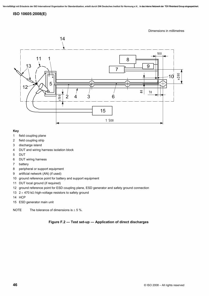
ISO 10605:2008(E)
46 © ISO 2008 – All rights reserved
Dimensions in millimetres
Key 1 field coupling plane 2 field coupling strip 3 discharge island 4 DUT and wiring harness isolation block 5 DUT 6 DUT wiring harness 7 battery 8 peripheral or support equipment 9 artificial network (AN) (if used) 10 ground reference point for battery and support equipment 11 DUT local ground (if required) 12 ground reference point for ESD coupling plane, ESD generator and safety ground connection 13 2 × 470 kΩ high-voltage resistors to safety ground 14 HCP 15 ESD generator main unit
NOTE The tolerance of dimensions is ± 5 %.
Figure F.2 — Test set-up — Application of direct discharges
Vervielfältigt mit Erlaubnis der ISO International Organization for Standardization, erteilt durch DIN Deutsches Institut für Normung e.V., in das interne Netzwerk der TÜV Rheinland Group eingespeichert.

ISO 10605:2008(E)
© ISO 2008 – All rights reserved 47
Dimensions in millimetres
Key 1 field coupling plane 2 field coupling strip 3 discharge island 4 DUT and wiring harness isolation block 5 DUT 6 DUT wiring harness 7 battery 8 peripheral or support equipment 9 AN (if used) 10 ground reference point for battery and support equipment 11 DUT local ground (if required) 12 ground reference point for ESD coupling plane, ESD generator and safety ground connection 13 2 × 470 kΩ high voltage resistors to safety ground 14 HCP 15 ESD generator main unit
NOTE The tolerance of dimensions is ± 5 %.
Figure F.3 — Test set-up — Application of indirect discharges
The ESD test bench ground plane (HCP) shall be a minimum of 0,5 m from other conductive structures, such as the surfaces of a shielded room, and shall be connected to safety ground with a connection that contains 2 × 470 kΩ high-voltage resistors, one at each end of the grounding conductor, with one end terminating on the HCP at point 3 shown in Figures F.2 and F.3.
Before testing commences, the discharge output voltage of the ESD simulator shall be verified in accordance with 6.1.
The ESD simulator shall have its ground referenced at point 3 shown in Figures F.2 and F.3.
Vervielfältigt mit Erlaubnis der ISO International Organization for Standardization, erteilt durch DIN Deutsches Institut für Normung e.V., in das interne Netzwerk der TÜV Rheinland Group eingespeichert.
ISO 10605:2008(E)
48 © ISO 2008 – All rights reserved
The DUT shall be positioned on the ESD field coupling plane and a 1 700 ( )3000
+ mm wiring harness shall be
connected from the DUT to its power supply and support equipment along the conductive trace on top of the ESD field coupling strip. The harness shall exit the DUT harness support 10 mm from the edge of the discharge island most distant from the DUT. The ground reference for the DUT wiring harness and load box is at point 10 shown in Figures F.2 and F.3.
The DUT coupling plane shall be large enough so as to extend beyond the DUT on all sides by at least 10 mm.
The ground connection (wiring) of the DUT shall be connected according to the intended grounding configuration in the vehicle [for local ground, directly connect to point 3 and for remote ground connect to point 10 via the wiring harness, in Figures F.2 and F.3].
If the case of the DUT is conductive and is grounded in the vehicle application, it shall be grounded to the DUT ESD field coupling plane or at point 3 in Figures F.2 and F.3.
The battery ground shall be electrically connected to the HCP at point 10 shown in Figures F.2 and F.3.
All of the switches, displays, sensors, actuators, etc. required to operate the DUT shall be part of the test configuration. Wherever possible, production intent parts and wiring shall be used.
Any peripheral support equipment shall be separated from the field coupling strip by at least 200 mm.
F.4 Test procedure
F.4.1 DUT software/DUT operating state
The DUT shall be activated in all modes defined in the test plan.
F.4.2 ESD powered-up test — Direct discharge
Refer to Figure F.2 for the set-up information. The discharges shall be applied to all accessible points on the DUT that can be touched during normal operation (surfaces, tip switches, switches, connectors, antennas, displays etc., as well as the diagnostic plug with pins). Ungrounded conductive surfaces shall be tested for subsequent voltage breakdown at the desired test voltage. The individual discharge points shall be specified in the test plan.
DUTs that are accessible to occupants inside the vehicle shall be tested using an ESD simulator with a discharge network of 330 pF and 330 Ω; otherwise, use a discharge network of 150 pF and 330 Ω. Refer to Clause C.4 for discharge probe and test level information.
All test points shall be tested with the required test voltage steps and both polarities. Suggested test levels are given in Clause C.4.
For each polarity and test voltage, 10 contact discharges to conductive points on the DUT, only as defined in the test plan, shall be carried out at each of the specified discharge points. In this process, the ESD simulator with the contact discharge electrode shall be positioned on the device and then discharged.
For each polarity and test voltage, 10 air discharges shall be carried out at each of the specified discharge points. In this process, the ESD simulator with the air discharge electrode shall be moved towards the discharge point as quickly as possible until discharge occurs.
Between two individual discharges, the charge applied shall be removed via a grounded discharge resistor with approximately 1 MΩ resistance (e.g. 2 × 470 kΩ resistors in series) by touching the discharge point and the housing. Alternatively, a duration of at least 2 s can be allowed to pass between two discharges.
The performance of the DUT shall be monitored and recorded according to the test plan.
Vervielfältigt mit Erlaubnis der ISO International Organization for Standardization, erteilt durch DIN Deutsches Institut für Normung e.V., in das interne Netzwerk der TÜV Rheinland Group eingespeichert.
ISO 10605:2008(E)
© ISO 2008 – All rights reserved 49
F.4.3 ESD Powered-up test — Indirect discharge
Refer to Figure F.3 for the set-up information.
The ESD simulator shall have a discharge network of 330 pF and 330 Ω and the contact discharge electrode shall be used.
For each polarity and test voltage, 10 contact discharges shall be applied in the centre of the free area not covered by the wiring harness at each of the three specified discharge islands. See key item 3 in Figure F.1 or Figure F.3 for these discharge islands.
For DUT with multiple harness branches (i.e. separate connectors), the branches shall be tested separately and as a combined bundle.
Do not discharge directly to the harness. If there are more than 40 lines in the harness bundle, the harness bundle shall be flipped over (180°) and the indirect coupled test repeated.
During this test, the DUT shall be monitored for effects. The default interval between discharges is 2 s minimum.
F.4.4 Suggested test severity levels
Examples of test severity levels are given in Clause C.4.
Vervielfältigt mit Erlaubnis der ISO International Organization for Standardization, erteilt durch DIN Deutsches Institut für Normung e.V., in das interne Netzwerk der TÜV Rheinland Group eingespeichert.

ISO 10605:2008(E)
50 © ISO 2008 – All rights reserved
Bibliography
[1] IEC 61000-4-2, Electromagnetic compatibility (EMC) — Part 4-2: Testing and measurement techniques — Electrostatic discharge immunity test
[2] ANSI C63.16-1993, Guide for electrostatic discharge test methodologies and criteria for electronic equipment
[3] FREI, S. and POMMERENKE, D., “An Analysis of the Fields on the Horizontal Coupling Plane in ESD Testing”, 1997 EOS/ESD Symposium, pp. 99-106
[4] MAAS, J., RHOADES, W., “The ANSI ESD Standard Overcoming the Deficiencies of World-Wide ESD Standards”, IEEE Int. Symp. on EMC, 1998, pp. 1078-1084
[5] DAOUT, B., RYSER, H., “The Correlation of Rising Slope and Speed of Approach in ESD Tests”, 12th International Zurich Symposium on EMC, 1987
[6] FREI, S., SENGHAAS, M., JOBAVA, R., KALKNER, W., “The Influence of Speed of Approach and Humidity on the Intensity of ESD”, International Zurich Symposium on Electromagnetic Compatibility, 1999
Vervielfältigt mit Erlaubnis der ISO International Organization for Standardization, erteilt durch DIN Deutsches Institut für Normung e.V., in das interne Netzwerk der TÜV Rheinland Group eingespeichert.

This page is intentionally blank.
Vervielfältigt mit Erlaubnis der ISO International Organization for Standardization, erteilt durch DIN Deutsches Institut für Normung e.V., in das interne Netzwerk der TÜV Rheinland Group eingespeichert.

This page is intentionally blank.
Vervielfältigt mit Erlaubnis der ISO International Organization for Standardization, erteilt durch DIN Deutsches Institut für Normung e.V., in das interne Netzwerk der TÜV Rheinland Group eingespeichert.

This page is intentionally blank.
Vervielfältigt mit Erlaubnis der ISO International Organization for Standardization, erteilt durch DIN Deutsches Institut für Normung e.V., in das interne Netzwerk der TÜV Rheinland Group eingespeichert.
ISO 10605:2008(E)
ICS 43.040.10 Price based on 50 pages
© ISO 2008 – All rights reserved
Vervielfältigt mit Erlaubnis der ISO International Organization for Standardization, erteilt durch DIN Deutsches Institut für Normung e.V., in das interne Netzwerk der TÜV Rheinland Group eingespeichert.