rm2255 de 1v3 - ion · leica rm2255 rotary microtome instructions for use leica rm2255 v1.6 rev a...
TRANSCRIPT

Leica RM2255Rotary Microtome
Instructions for UseLeica RM2255V1.6 Rev A English – 10/2011Order no. 14 0502 80101Always keep this manual with the instrument.Read carefully before working with the instrument.

3Leica RM2255
The information, numerical data, notes and val-ue judgments contained in this manual repre-sent the current state of scientific knowledgeand state-of-the-art technology as we under-stand it following thorough investigation in thisfield.We are under no obligation to update thepresent manual periodically and on an ongoingbasis according to the latest technical develop-ments, nor to provide our customers with addi-tional copies, updates etc. of this manual.For erroneous statements, drawings, technicalillustrations etc. contained in this manual weexclude liability as far as permissible accordingto the national legal system applicable in eachindividual case.In particular, no liability whatsoever is accept-ed for any financial loss or consequential dam-age caused by or related to compliance withstatements or other information in this manual.Statements, drawings, illustrations and other in-formation as regards contents or technical de-tails of the present Instructions for Use are notto be considered as warranted characteristicsof our products.
These are determined only by the contract pro-visions agreed between ourselves and our cus-tomers.Leica reserves the right to change technicalspecifications as well as manufacturing pro-cesses without prior notice. Only in this way is itpossible continuously to improve the technolo-gy and manufacturing techniques used in ourproducts.This document is protected under copyrightlaws. Any copyrights of this document areretained by Leica Biosystems Nussloch GmbH.Any reproduction of text and illustrations (or ofany parts thereof) by means of print, photocopy,microfiche, web cam or other methods – includ-ing any electronic systems and media –requires express prior permission in writing byLeica Biosystems Nussloch GmbH.For the instrument serial number and year ofmanufacture, please refer to the identificationlabel attached to the instrument.
© Leica Biosystems Nussloch GmbH
NOTE
Published by:Leica Biosystems Nussloch GmbHHeidelberger Str. 17-19D-69226 NusslochGermanyPhone: +49 6224 143-0Fax: +49 6224 143-268Internet: http://www.leica-microsystems.com

4 Instructions for Use V 1.6 RevA – 10/2011
Table of contents
1. Important notes ....................................................................................................................................... 61.1 Symbols used in this manual and their meaning .............................................................................. 61.2 Qualification of personnel .................................................................................................................... 71.3 Designated use ....................................................................................................................................... 71.4 Instrument type ...................................................................................................................................... 7
2. Safety ........................................................................................................................................................ 82.1 Safety notes ............................................................................................................................................ 82.2 Warnings ................................................................................................................................................. 82.3 Integrated safety devices ................................................................................................................... 11
3. Instrument components and specifications .................................................................................... 133.1 Overview — instrument components ............................................................................................... 133.2 Instrument Specifications .................................................................................................................. 143.3 Technical data ...................................................................................................................................... 15
4. Startup .................................................................................................................................................... 174.1 Installation site requirements ............................................................................................................ 174.2 Standard delivery ................................................................................................................................. 174.3 Unpacking and installation ................................................................................................................. 184.4 Assembling the handwheel ................................................................................................................ 204.5 Electrical connections ........................................................................................................................ 20
5. Operation ................................................................................................................................................ 235.1 Operating elements and their functions ........................................................................................... 235.1.1 Instrument control panel .................................................................................................................... 235.1.2 Control panel ......................................................................................................................................... 245.2 Switching on the instrument .............................................................................................................. 255.3 Display and control elements ............................................................................................................ 265.4 Inserting the knife holder .................................................................................................................... 375.5 Inserting the universal cassette clamp ............................................................................................ 385.6 Adjusting the clearance angle ........................................................................................................... 395.7 Clamping the specimen....................................................................................................................... 405.8 Clamping the knife/disposable blade ................................................................................................ 405.9 Trimming the specimen....................................................................................................................... 425.9.1 Trimming in manual sectioning mode ............................................................................................... 425.9.2 Trimming in motorized sectioning mode .......................................................................................... 425.10 Sectioning ............................................................................................................................................. 435.11 Changing the specimen or interrupting sectioning ........................................................................ 43
6. Optional accessories ........................................................................................................................... 446.1 Assembly for specimen holder fixture .............................................................................................. 446.1.1 Non-orientable specimen holder fixture .......................................................................................... 446.1.2 Directional fixture for specimen clamps .......................................................................................... 44

5Leica RM2255
Table of contents
6.1.3 Fine-directional specimen holder fixture ......................................................................................... 456.1.4 Quick clamping system ....................................................................................................................... 466.2 Specimen clamps and holders .......................................................................................................... 476.2.1 Standard specimen clamp .................................................................................................................. 476.2.2 Vee insert .............................................................................................................................................. 486.2.3 Foil clamp type 1 ................................................................................................................................... 496.2.4 Foil clamp type 2 ................................................................................................................................... 506.2.5 Universal cassette clamp ................................................................................................................... 51
Universal cassette clamp, ice-cooled .............................................................................................. 526.2.6 Round specimen holder ...................................................................................................................... 526.2.7 Super mega-cassette clamp .............................................................................................................. 536.3 Knife holder base and knife holder ................................................................................................... 546.3.1 Knife holder base, without lateral movement feature ................................................................... 546.3.2 Knife holder E/E-TC .............................................................................................................................. 556.3.3 Knife holder N/NZ ................................................................................................................................ 586.4 Blades/knives ....................................................................................................................................... 606.4.1 Disposable blades ................................................................................................................................ 606.4.2 Knife ....................................................................................................................................................... 606.5 Section waste tray ............................................................................................................................... 626.6 Backlighting .......................................................................................................................................... 626.7 Tray ........................................................................................................................................................ 636.8 Freezer pack ......................................................................................................................................... 636.9 Universal microscope carrier ............................................................................................................ 646.10 Magnifier ............................................................................................................................................... 666.11 Cold light source .................................................................................................................................. 676.12 Fiber optic light guides ........................................................................................................................ 676.13 Ordering information ........................................................................................................................... 68
7. Customized solutions ........................................................................................................................... 707.1 Instrument malfunctions ..................................................................................................................... 707.1.1 Error messages .................................................................................................................................... 707.1.2 Malfunctions, possible causes and troubleshooting ..................................................................... 707.2 Possible faults ...................................................................................................................................... 72
8. Cleaning and maintenance ................................................................................................................. 748.1 Cleaning the instrument ...................................................................................................................... 748.2 Maintenance ........................................................................................................................................ 768.2.1 Replacing fuses .................................................................................................................................... 768.2.2 Maintenance instructions .................................................................................................................. 778.2.3 Lubricating the instrument ................................................................................................................. 78
9. Warranty and service .......................................................................................................................... 79
6 Instructions for Use V 1.6 RevA – 10/2011
1. Important notes
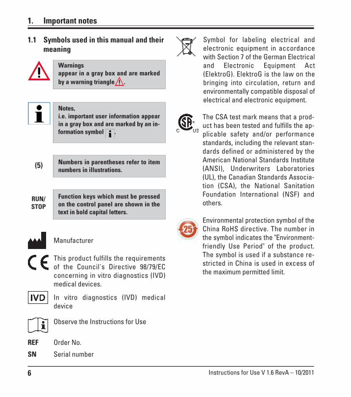
Function keys which must be pressedon the control panel are shown in thetext in bold capital letters.
1.1 Symbols used in this manual and theirmeaning
(5) Numbers in parentheses refer to itemnumbers in illustrations.
Notes,i.e. important user information appearin a gray box and are marked by an in-formation symbol .
Warningsappear in a gray box and are markedby a warning triangle .
RUN/STOP
REF
SN
Manufacturer
This product fulfills the requirementsof the Council's Directive 98/79/ECconcerning in vitro diagnostics (IVD)medical devices.
In vitro diagnostics (IVD) medicaldevice
Observe the Instructions for Use
Order No.
Serial number
The CSA test mark means that a prod-uct has been tested and fulfills the ap-plicable safety and/or performancestandards, including the relevant stan-dards defined or administered by theAmerican National Standards Institute(ANSI), Underwriters Laboratories(UL), the Canadian Standards Associa-tion (CSA), the National SanitationFoundation International (NSF) andothers.
Symbol for labeling electrical andelectronic equipment in accordancewith Section 7 of the German Electricaland Electronic Equipment Act(ElektroG). ElektroG is the law on thebringing into circulation, return andenvironmentally compatible disposal ofelectrical and electronic equipment.
Environmental protection symbol of theChina RoHS directive. The number inthe symbol indicates the "Environment-friendly Use Period" of the product.The symbol is used if a substance re-stricted in China is used in excess ofthe maximum permitted limit.

7Leica RM2255
1.4 Instrument type
All information provided in these Instructionsfor Use applies only to the instrument type indi-cated on the title page.An identification label with the serial number isfastened to the left side of the instrument (thisfigure is only symbolic).
Fig. 1
1.2 Qualification of personnel
• The Leica RM2255 may be operated bytrained laboratory personnel only.
• All laboratory personnel designated to oper-ate the Leica instrument must read these In-structions for Use carefully and must be fa-miliar with all technical features of theinstrument before attempting to operate it.
1.3 Designated use
The Leica RM2255 is a fully automatic, motor-ized rotary microtome with a separate controlpanel for creating thin sections of specimens ofvarying hardness for use in routine and re-search laboratories in the fields of biology,medicine and industry.It is designed for cutting both soft paraffin andharder specimens, as long as they are suitablefor being cut manually or automatically.
Any other use of the instrument is consideredimproper!
1. Important information

8 Instructions for Use V 1.6 RevA – 10/2011
2. Safety
2.1 Safety notes
These Instructions for Use include important in-formation related to the operating safety andmaintenance of the instrument.The instruction manual is an important part ofthe product, which must be read carefully priorto startup and use and must always be keptnear the instrument.
These Instructions for Use must be ap-propriately supplemented as requiredby the existing regulations on acci-dent prevention and environmentalsafety in the operator's country.
Be sure to comply with the safety instructions and warnings provided in this chapter.Be sure to read these instructions, even if you are already familiar with the operation and useof other Leica products.
This instrument has been built and tested in ac-cordance with the safety regulations for electri-cal measuring, control, regulating and laborato-ry devices.
To maintain this condition and ensure safe op-eration, the user must observe all notes andwarnings contained in these Instructions forUse.For current information about applicable stan-dards, please refer to the CE declaration of con-formity on our Internet site:
www.leica-microsystems.com
The protective devices on both instrument and accessories may neither be removed nor modi-fied. Only service personnel qualified by Leica may repair the instrument and access the in-strument’s internal components.
2.2 Warnings
The safety devices installed in this instrument by the manufacturer only constitute the basisfor accident prevention. Primarily responsible for accident-free operation is above all the own-er of the instrument and, in addition, the designated personnel who operates, services orcleans the instrument.To ensure trouble-free operation of the instrument, make sure to comply with the following in-structions and warnings.
9Leica RM2255
2. Safety
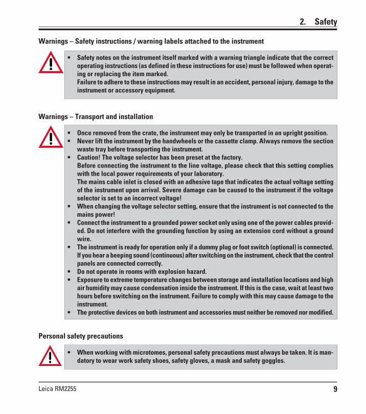
Warnings – Safety instructions / warning labels attached to the instrument
• Safety notes on the instrument itself marked with a warning triangle indicate that the correctoperating instructions (as defined in these instructions for use) must be followed when operat-ing or replacing the item marked.Failure to adhere to these instructions may result in an accident, personal injury, damage to theinstrument or accessory equipment.
Warnings – Transport and installation
• Once removed from the crate, the instrument may only be transported in an upright position.• Never lift the instrument by the handwheels or the cassette clamp. Always remove the section
waste tray before transporting the instrument.• Caution! The voltage selector has been preset at the factory.
Before connecting the instrument to the line voltage, please check that this setting complieswith the local power requirements of your laboratory.The mains cable inlet is closed with an adhesive tape that indicates the actual voltage settingof the instrument upon arrival. Severe damage can be caused to the instrument if the voltageselector is set to an incorrect voltage!
• When changing the voltage selector setting, ensure that the instrument is not connected to themains power!
• Connect the instrument to a grounded power socket only using one of the power cables provid-ed. Do not interfere with the grounding function by using an extension cord without a groundwire.
• The instrument is ready for operation only if a dummy plug or foot switch (optional) is connected.If you hear a beeping sound (continuous) after switching on the instrument, check that the controlpanels are connected correctly.
• Do not operate in rooms with explosion hazard.• Exposure to extreme temperature changes between storage and installation locations and high
air humidity may cause condensation inside the instrument. If this is the case, wait at least twohours before switching on the instrument. Failure to comply with this may cause damage to theinstrument.
• The protective devices on both instrument and accessories must neither be removed nor modified.
Personal safety precautions
• When working with microtomes, personal safety precautions must always be taken. It is man-datory to wear work safety shoes, safety gloves, a mask and safety goggles.
10 Instructions for Use V 1.6 RevA – 10/2011
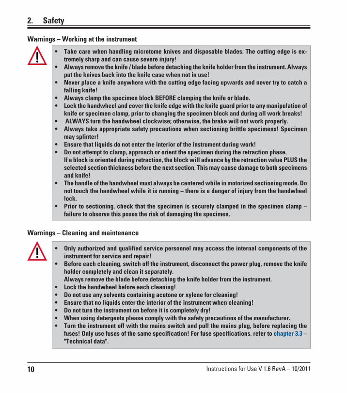
Warnings – Cleaning and maintenance
• Only authorized and qualified service personnel may access the internal components of theinstrument for service and repair!
• Before each cleaning, switch off the instrument, disconnect the power plug, remove the knifeholder completely and clean it separately.Always remove the blade before detaching the knife holder from the instrument.
• Lock the handwheel before each cleaning!• Do not use any solvents containing acetone or xylene for cleaning!• Ensure that no liquids enter the interior of the instrument when cleaning!• Do not turn the instrument on before it is completely dry!• When using detergents please comply with the safety precautions of the manufacturer.• Turn the instrument off with the mains switch and pull the mains plug, before replacing the
fuses! Only use fuses of the same specification! For fuse specifications, refer to chapter 3.3 –"Technical data".
2. Safety
• Take care when handling microtome knives and disposable blades. The cutting edge is ex-tremely sharp and can cause severe injury!
• Always remove the knife / blade before detaching the knife holder from the instrument. Alwaysput the knives back into the knife case when not in use!
• Never place a knife anywhere with the cutting edge facing upwards and never try to catch afalling knife!
• Always clamp the specimen block BEFORE clamping the knife or blade.• Lock the handwheel and cover the knife edge with the knife guard prior to any manipulation of
knife or specimen clamp, prior to changing the specimen block and during all work breaks!• ALWAYS turn the handwheel clockwise; otherwise, the brake will not work properly.• Always take appropriate safety precautions when sectioning brittle specimens! Specimen
may splinter!• Ensure that liquids do not enter the interior of the instrument during work!• Do not attempt to clamp, approach or orient the specimen during the retraction phase.
If a block is oriented during retraction, the block will advance by the retraction value PLUS theselected section thickness before the next section. This may cause damage to both specimensand knife!
• The handle of the handwheel must always be centered while in motorized sectioning mode. Donot touch the handwheel while it is running – there is a danger of injury from the handwheellock.
• Prior to sectioning, check that the specimen is securely clamped in the specimen clamp –failure to observe this poses the risk of damaging the specimen.
Warnings – Working at the instrument

11Leica RM2255
2.3 Integrated safety devices
2. Safety
Fig. 2
Fig. 3
3
1
4
2
5
Handwheel lock (manual operation only)• To lock the handwheel, push the lever (5) outwards and
continue to turn the handwheel slowly until it locksexactly in the 12 o’clock position. The LED (4) in theLOCK display lights up.
Caution!Never operate the lever (5) during motorizedsectioning.
Handwheel brakeUsing the lever (3) on the right side of the microtome baseplate, the handwheel can be braked in any position.• To lock the handwheel, pull the lever forward forcefully.• To unlock the handwheel brake, push the locking lever
(3) back to its original position.
Emergency-stop functionThe emergency-stop function is activated with the redEMERGENCY STOP switch (1) on the upper left of the frontof the microtome. The sectioning motor stops immediatelywhen the EMERGENCY STOP switch is pressed. The redLED in the E-STOP field (2) on the control panel of theinstrument lights up, indicating that the emergency stopfunction has been activated.To deactivate this function, turn the EMERGENCY STOPswitch in the direction of the arrow.
2
12
Important!The LED (4) in the M-STOP field indicates only that the instrument cannot be started. It does notprovide any indication that the handwheel brake is active.The lever (3) must be pulled completely forward with force so that the handwheel brake isapplied. The handwheel is securely locked only when the lever (5) is in the 12 o’clock position.
12 Instructions for Use V 1.6 RevA – 10/2011
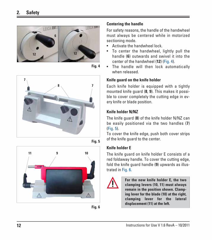
2. Safety
Knife guard on the knife holderEach knife holder is equipped with a tightlymounted knife guard (8, 9). This makes it possi-ble to cover completely the cutting edge in ev-ery knife or blade position.
Knife holder N/NZThe knife guard (8) of the knife holder N/NZ canbe easily positioned via the two handles (7)(Fig. 5).To cover the knife edge, push both cover stripsof the knife guard to the center.
Knife holder EThe knife guard on knife holder E consists of ared foldaway handle. To cover the cutting edge,fold the knife guard handle (9) upwards as illus-trated in Fig. 6.
For the new knife holder E, the twoclamping levers (10, 11) must alwaysremain in the position shown. Clamp-ing lever for the blade (10) at the right,clamping lever for the lateraldisplacement (11) at the left.
7
78
Fig. 5
Fig. 6
Centering the handleFor safety reasons, the handle of the handwheelmust always be centered while in motorizedsectioning mode.• Activate the handwheel lock.• To center the handwheel, lightly pull the
handle (6) outwards and swivel it into thecenter of the handwheel (12) (Fig. 4).
• The handle will then lock automaticallywhen released.
Fig. 4
9 1011
6
12 12

13Leica RM2255
3.1 Overview — instrument components
3. Instrument components and specifications
Handwheelhandle with
centering function
Leica RM2255
Knife guard on theknife holder
Smooth-turningHandwheel
Lever foractivating the
handwheelbrake
Handwheellocking
mechanism
Separate control panel
Fig. 7
Knife holder base
Knife holder NZ
Section waste tray
Standard clamp
Emergency-stopswitch
Control panelon the
instrument
Clamping leverof knife holder base
Socket forbacklighting
14 Instructions for Use V 1.6 RevA – 10/2011
3. Instrument components and specifications
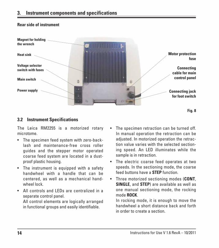
Fig. 8
Motor protectionfuse
Heat sink
Voltage selectorswitch with fuses
Main switch
Power supply
Connectingcable for main
control panel
Connecting jackfor foot switch
3.2 Instrument Specifications
The Leica RM2255 is a motorized rotarymicrotome.• The specimen feed system with zero-back-
lash and maintenance-free cross rollerguides and the stepper motor operatedcoarse feed system are located in a dust-proof plastic housing.
• The instrument is equipped with a safetyhandwheel with a handle that can becentered, as well as a mechanical hand-wheel lock.
• All controls and LEDs are centralized in aseparate control panel.All control elements are logically arrangedin functional groups and easily identifiable.
• The specimen retraction can be turned off.In manual operation the retraction can beadjusted. In motorized operation the retrac-tion value varies with the selected section-ing speed. An LED illuminates while thesample is in retraction.
• The electric coarse feed operates at twospeeds. In the sectioning mode, the coarsefeed buttons have a STEP function.
• Three motorized sectioning modes (CONT,SINGLE, and STEP) are available as well asone manual sectioning mode, the rockingmode ROCK.In rocking mode, it is enough to move thehandwheel a short distance back and forthin order to create a section.
Rear side of instrument
Magnet for holdingthe wrench

15Leica RM2255
3.3 Technical dataGeneral
Approvals: The instrument-specific approval marks are locatednext to the identification label.
Nominal supply voltages: 100 / 120 / 230 / 240 V AC ±10%Nominal frequency: 50/60 HzMaximum power consumption 340 VAProtection class : IPower fuses 2 x T 3.2 A UL listedPollution degree : 2Overvoltage category : IIMaximum heat emission: 340 J/sOperating temperature range: +10 °C to +35 °CTemperature range during storage: +5 °C to +55 °CRelative humidity: max. 80 %, non-condensingStorage humidity: < 80%
according to IEC-1010, UL 3101, EN 61010
Dimensions and weight
Basic instrumentWidth (including handwheel): 413 mmWidth (excluding handwheel): 300 mmDepth (including waste tray): 618 mmHeight (total): 305 mm (with tray on the hood)Working height (knife blade): 100 mm (measured from the base plate)Working height (knife blade): 168 mm (measured from the table)
Weight (without accessories) approx. 37 kg
Control panelWidth: 121 mmDepth: 166 mmHeight: 50 mmHeight (in inclined position): 81 mm
Weight (net): approx. 0.660 kg
3. Instrument components and specifications

16 Instructions for Use V 1.6 RevA – 10/2011
3. Instrument components and specifications
Microtome
Sectioning thickness setting:Section thickness setting range: 0.50 – 100 µmSetting: 0.50 – 5.0 µm in 0.5 µm increments
5.0 – 20.0 µm in 1.0 µm increments 20.0 – 60.0 µm in 5.0 µm increments 60.0 –100.0 µm in 10.0 µm increments
Trimming section thickness setting range: 1 – 600 µmSetting: 1.0 – 10.0 µm in 1.0 µm increments,
10.0 – 20.0 µm in 2.0 µm increments, 20.0 – 50.0 µm in 5.0 µm increments, 50.0 – 100.0 µm in 10.0 µm increments, 100.0 – 600.0 µm in 50.0 µm increments.
Object feed: 28 mm ±1 mm, feed motion via step motor
Vertical stroke: 70 mmMaximum sectioning area w/o retraction: 65 mm without specimen orientationMaximum sectioning area with retraction: 60 mm
Specimen retraction:in manual sectioning mode: 5 - 100 µm in 5 µm increments; can be turned offin motorized sectioning mode: Varies with the sectioning speed; can be turned off
Electric coarse feed: 300 µm/s and 900 µm/s
Sectioning speed: 0; 0.5 - 420 mm/s ± 10%
Return speed approx. 120 - 420 mm/s ± 10%
Repositioning of knife holder baseNorth-south: ± 24 mmEast-west movement: ± 23 mm
Maximum specimen size (L x H x W): 50 x 60 x 40 mm
Specimen orientationHorizontal: 8°Vertical: 8°
17Leica RM2255
4. Startup
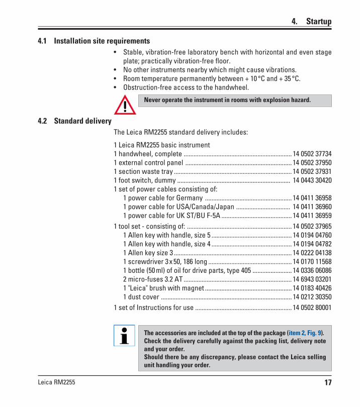
4.2 Standard deliveryThe Leica RM2255 standard delivery includes:
1 Leica RM2255 basic instrument1 handwheel, complete .................................................................. 14 0502 377341 external control panel ................................................................. 14 0502 379501 section waste tray ........................................................................ 14 0502 379311 foot switch, dummy ..................................................................... 14 0443 304201 set of power cables consisting of:
1 power cable for Germany ..................................................... 14 0411 369581 power cable for USA/Canada/Japan ................................. 14 0411 369601 power cable for UK ST/BU F-5A ........................................... 14 0411 36959
1 tool set - consisting of: ................................................................ 14 0502 379651 Allen key with handle, size 5 ................................................. 14 0194 047601 Allen key with handle, size 4 ................................................. 14 0194 047821 Allen key size 3 ........................................................................ 14 0222 041381 screwdriver 3 x 50, 186 long ................................................... 14 0170 115681 bottle (50 ml) of oil for drive parts, type 405 ........................ 14 0336 060862 micro-fuses 3.2 AT .................................................................. 14 6943 032011 "Leica" brush with magnet ..................................................... 14 0183 404261 dust cover ................................................................................ 14 0212 30350
1 set of Instructions for use ........................................................... 14 0502 80001
The accessories are included at the top of the package (item 2, Fig. 9).Check the delivery carefully against the packing list, delivery noteand your order.Should there be any discrepancy, please contact the Leica sellingunit handling your order.
4.1 Installation site requirements• Stable, vibration-free laboratory bench with horizontal and even stage
plate; practically vibration-free floor.• No other instruments nearby which might cause vibrations.• Room temperature permanently between + 10 °C and + 35 °C.• Obstruction-free access to the handwheel.
Never operate the instrument in rooms with explosion hazard.

18 Instructions for Use V 1.6 RevA – 10/2011
4. Startup
4.3 Unpacking and installation
When the instrument is delivered, check the tilt indicators on thepackaging.If the arrowhead is blue, the shipment was transported laying flat,was tilted at too great an angle or fell over during transport.Note this on the shipping documents and check the shipment forpossible damage.
Fig. 9
Fig. 10
1
2
3
4
4
4
4
5
• Loosen and unscrew the six upperscrews (2).
• Remove the cover (1).• Take the accessory carton (optional
accessories) (3) and the cartons (4)from the standard scope of delivery.
The transport crate and includ-ed retaining elements shouldbe kept in case a return ship-ment is necessary later.
19Leica RM2255
65
4.3 Unpacking and installation (continued)
Fig. 10a
7
9
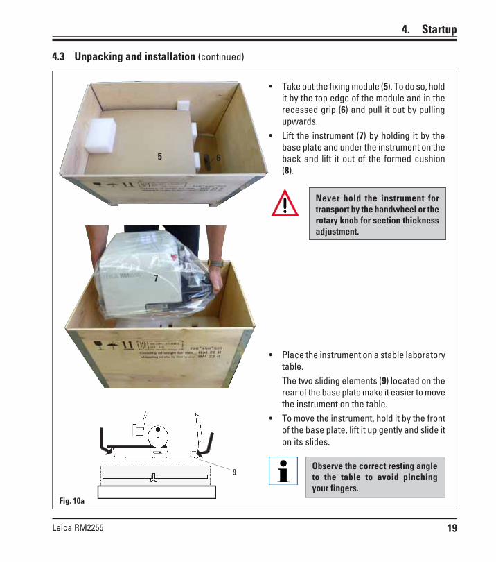
• Take out the fixing module (5). To do so, holdit by the top edge of the module and in therecessed grip (6) and pull it out by pullingupwards.
• Lift the instrument (7) by holding it by thebase plate and under the instrument on theback and lift it out of the formed cushion(8).
Never hold the instrument fortransport by the handwheel or therotary knob for section thicknessadjustment.
Observe the correct resting angleto the table to avoid pinchingyour fingers.
• Place the instrument on a stable laboratorytable.The two sliding elements (9) located on therear of the base plate make it easier to movethe instrument on the table.
• To move the instrument, hold it by the frontof the base plate, lift it up gently and slide iton its slides.
4. Startup
20 Instructions for Use V 1.6 RevA – 10/2011
4. Startup
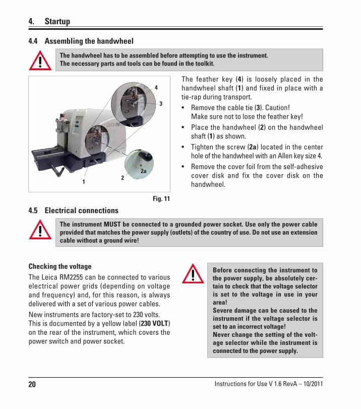
The feather key (4) is loosely placed in thehandwheel shaft (1) and fixed in place with atie-rap during transport.• Remove the cable tie (3). Caution!
Make sure not to lose the feather key!• Place the handwheel (2) on the handwheel
shaft (1) as shown.• Tighten the screw (2a) located in the center
hole of the handwheel with an Allen key size 4.• Remove the cover foil from the self-adhesive
cover disk and fix the cover disk on thehandwheel.
4.4 Assembling the handwheel
Fig. 11
The handwheel has to be assembled before attempting to use the instrument.The necessary parts and tools can be found in the toolkit.
4.5 Electrical connections
The instrument MUST be connected to a grounded power socket. Use only the power cableprovided that matches the power supply (outlets) of the country of use. Do not use an extensioncable without a ground wire!
Before connecting the instrument tothe power supply, be absolutely cer-tain to check that the voltage selectoris set to the voltage in use in yourarea!Severe damage can be caused to theinstrument if the voltage selector isset to an incorrect voltage!Never change the setting of the volt-age selector while the instrument isconnected to the power supply.
Checking the voltageThe Leica RM2255 can be connected to variouselectrical power grids (depending on voltageand frequency) and, for this reason, is alwaysdelivered with a set of various power cables.New instruments are factory-set to 230 volts.This is documented by a yellow label (230 VOLT)on the rear of the instrument, which covers thepower switch and power socket.
22a
3
4
1

21Leica RM2255
4. Startup
22
2524 2123
The voltage selector is located above the mainpower switch, on the left-rear side of the instru-ment (Fig. 12). The voltage setting is displayed inthe viewing window (22).• Insert a small screwdriver into the cutout
(25) and carefully pry out the insert.• Remove the voltage selector housing (21) to-
gether with the fuses (23). Remove the volt-age selector block (24) (white) and insert itagain such that the correct local voltage isdisplayed in the viewing window (22).
• Reinsert the voltage selector housing withthe block and fuses and push it in until it en-gages (audible click).
21
26
Connecting the power supply
• Before connecting the power cable, make sure that the power switch(27) on the rear of the instrument is switched to 'O' = OFF.
• Various country-specific power cables are provided with the instru-ment. Make sure that the power cable used has the correct plug forthe power socket.
• Insert the connector of the power cable into the connection socket(26) and plug the power plug into the power socket.
Exposure to extreme temperature changes and high air humiditymay cause condensation to form inside the instrument.After transporting, please wait at least 2 hours to allow the instru-ment to adopt the ambient temperature before turning it on!Failure to comply with this may cause damage to the instrument.
27
Fig. 12
Checking the voltage (continued)
22 Instructions for Use V 1.6 RevA – 10/2011
Fig. 13
4. Startup
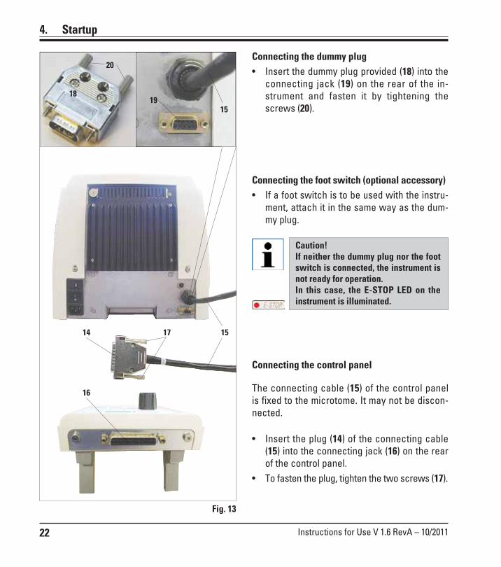
Connecting the control panel
The connecting cable (15) of the control panelis fixed to the microtome. It may not be discon-nected.
• Insert the plug (14) of the connecting cable(15) into the connecting jack (16) on the rearof the control panel.
• To fasten the plug, tighten the two screws (17).
Connecting the dummy plug• Insert the dummy plug provided (18) into the
connecting jack (19) on the rear of the in-strument and fasten it by tightening thescrews (20).
Connecting the foot switch (optional accessory)• If a foot switch is to be used with the instru-
ment, attach it in the same way as the dum-my plug.
Caution!If neither the dummy plug nor the footswitch is connected, the instrument isnot ready for operation.In this case, the E-STOP LED on theinstrument is illuminated.
18
15
19
20
16
15
14 17
23Leica RM2255
5. Operation
5.1 Operating elements and their functions
The operating functions of the microtome are divided between a control panel and a displayunit on the microtome.A control panel on the instrument displays the current operating mode as well as varioussettings.All operating functions are centrally located in the separate control panel. All keys anddisplays are logically arranged in functional groups and easily identifiable.
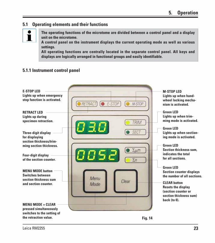
5.1.1 Instrument control panel
Three-digit displayfor displayingsection thickness/trim-ming section thickness.
Four-digit displayof the section counter.
MENU MODE + CLEARpressed simultaneouslyswitches to the setting ofthe retraction value.
Green LEDSection thickness sum,indicates the totalfor all sections.
Green LEDSection counter displaysthe number of all sections.
CLEAR buttonResets the display(section counter orsection thickness sum)back (to 0).
MENU MODE buttonSwitches betweensection thickness sumand section counter.
E-STOP LEDLights up when emergencystop function is activated.
M-STOP LEDLights up when hand-wheel locking mecha-nism is activated.
RETRACT LEDLights up duringspecimen retraction.
Green LEDLights up when trim-ming mode is activated.
Green LEDLights up when section-ing mode is activated.
Fig. 14

24 Instructions for Use V 1.6 RevA – 10/2011
5. Operation
Three-digit display forsection thickness/trimming sectionthickness.
Green LEDLights up when trimmingmode is activated.
Green LEDLights up when section-ing mode is activated.
5.1.2 Control panel
Green LEDsFor displaying the ac-tive operating mode
Rotary knobfor setting thesectioningspeed.
ButtonsStart/stop motorizedsectioning.
Buttonsfor setting the sec-tion thickness/trim-ming section thick-ness.
TRIM/SECT buttonFor switching betweensectioning mode andtrimming mode.
CUT MODE buttonMode selection
ButtonSet sectioning windowYellow LED
Flashes during coarsefeed backwards; lightsup when rear end posi-tion is reached.
Yellow LEDFlashes during coarsefeed forwards; lightsup when front end po-sition is reached.
Coarse feedforwardfast
Coarse feedbackwardslow
Coarse feedbackwardfast
Multiplestepbackward
Multiplestepforward
Singlestepbackward
Coarse feedforwardslow
Singlestepforward
Trimming mode:
Sectioning mode:
Yellow LEDLights up whenmotor is switched on.Green LEDLights up whenthe motor is switchedoff or stops at the nextstop position.
Fig. 15
Coarse feed buttons
Green LEDFlashes until secondsectioning windowedge is set.
25Leica RM2255
5.2 Switching on the instrument
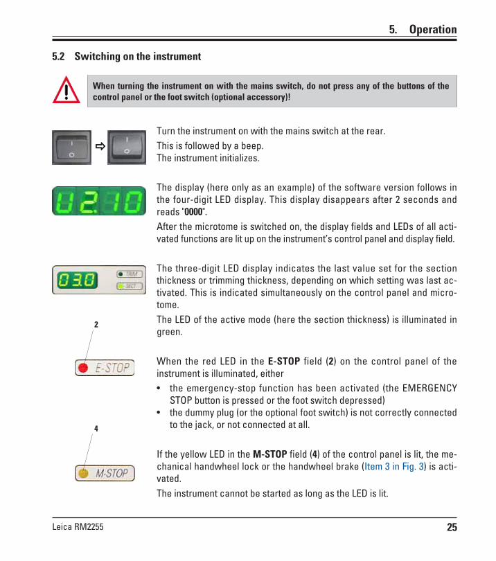
When turning the instrument on with the mains switch, do not press any of the buttons of thecontrol panel or the foot switch (optional accessory)!
Turn the instrument on with the mains switch at the rear.This is followed by a beep.The instrument initializes.
The display (here only as an example) of the software version follows inthe four-digit LED display. This display disappears after 2 seconds andreads "0000".After the microtome is switched on, the display fields and LEDs of all acti-vated functions are lit up on the instrument’s control panel and display field.
The three-digit LED display indicates the last value set for the sectionthickness or trimming thickness, depending on which setting was last ac-tivated. This is indicated simultaneously on the control panel and micro-tome.The LED of the active mode (here the section thickness) is illuminated ingreen.
When the red LED in the E-STOP field (2) on the control panel of theinstrument is illuminated, either• the emergency-stop function has been activated (the EMERGENCY
STOP button is pressed or the foot switch depressed)• the dummy plug (or the optional foot switch) is not correctly connected
to the jack, or not connected at all.
If the yellow LED in the M-STOP field (4) of the control panel is lit, the me-chanical handwheel lock or the handwheel brake (Item 3 in Fig. 3) is acti-vated.The instrument cannot be started as long as the LED is lit.
5. Operation
4
2

26 Instructions for Use V 1.6 RevA – 10/2011
Coarse feed functions
The electric coarse feed at two speeds is used for a rapid movement of thespecimen towards and away from the knife.With the double-arrow buttons, the coarse feed operates at 900 µm/s; with thesingle-arrow buttons, it runs at 300 µm/s. In sectioning mode, the coarse feedcan be operated in two different ways: defined step-by-step specimen feed(STEP function) and continuous movement of the specimen. The instrument isdelivered with the STEP function deactivated (standard configuration).
Setting the section thickness/trimming section thickness
Adjust these settings using the - keys on the control panel.
Section thickness setting range: 0.50 - 100 µmSetting: 0.5 - 5.0 µm in 0.5 µm increments
5.0 - 20.0 µm in 1.0 µm increments20.0 - 60.0 µm in 5.0 µm increments60.0 - 100.0 µm in 10.0 µm increments
Trimming section thickness setting range: 1 - 600 µmSetting: 1.0 - 10.0 µm in 1.0 µm increments,
10.0 - 20.0 µm in 2.0 µm increments,20.0 - 50.0 µm in 5.0 µm increments,50.0 - 100.0 µm in 10.0 µm increments,
100.0 - 600.0 µm in 50.0 µm increments.
Selecting the sectioning and trimming mode
To switch between sectioning mode and trimming mode, press the TRIMSECT button. Whenever the button is pressed, the display toggles be-tween SECT and TRIM.In the SECT display, the sectioning thickness in the range from 0.50 to100.0 µm is shown, and in the TRIM display, the trimming section thick-ness between 1.0 and 600 µm is displayed.
5. Operation
5.3 Display and control elements Three-digit display
This display is located both on the instrumentand on the control panel.If the SECT LED is lit up, the display shows thesection thickness setting in µm.If the TRIM LED is lit up, the display shows thetrimming section thickness setting in µm.Fig. 16

27Leica RM2255
When continuous feed is selected, the coarse feed buttons have the same func-tions as in trimming mode. The STEP function is useful for careful step-by-stepapproximation of the specimen towards the blade.How to activate the STEP function:• Switch the instrument on while holding the button on the control panel.
(Likewise, to deactivate switch the instrument on while pressing the but-ton.) While the instrument is initializing, hold the button until the softwareversion number is no longer displayed (ensure that version number 2.1 wasdisplayed).
• Press TRIM/SECT button and select sectioning mode (LED SECT lit).• When pressing a slow-speed coarse feed button (with an arrow) in STEP
mode, the specimen moves towards or away from the specimen by thevalue indicated on the display (single step).
• By short activation of the buttons for coarse feed (with two arrows), a sin-gle step is also effected in the appropriate direction.
• Longer activation of the double-arrow coarse feed button effects a repeat-ed feed motion for as long as the button is pressed.
5. Operation
• To start the rapid backwards movement (away from the blade) press the button.
After the button is pressed, the specimen head is moved to the rearend position.
• To stop the movement, press any of the four coarse feed buttons.• The yellow LED (40) in the button flashes while the object head is in mo-
tion, and remains lit continuously when the rear end position is reached.
40
Backwards coarse feed
Multiplestepbackward
Multiplestepforward
Singlestepbackward
Singlestepforward
Sectioning mode
Trimming mode
Button functions inSTEP mode
This feature is only available in sectioning mode in version 2.1 orhigher. If you have an earlier software version, please contactLeica Service.
In sectioning mode the user can select between STEP function(step-by-step specimen feed) and continuous specimen feed.
In the trimming mode, the coarse feed buttons operate a continuousmovement as long as the button is held down. The double-arrowbutton for rapid coarse feed backward movements has a lock-infunction.
Do not put your fingers between the specimen clamp and micro-tome to prevent pinching them.

28 Instructions for Use V 1.6 RevA – 10/2011
5. Operation
• To change the display mode, push MENU MODE until the LED of thedesired mode is illuminated.
• Press CLEAR to reset section thickness sum or section number.• This will only reset the currently displayed value.
Four-digit display on the instrumentThe four-digit display is adjustable.When the ΣΣΣΣΣ µm LED is lit, the display shows thesum of the section thicknesses in µm for all sec-tions completed since the instrument wasswitched on.(Section thickness sum)When the ΣΣΣΣΣn LED is lit, the display shows thenumber of all previously completed sections.Fig. 17
• Press the button to start the slow backwards movement.The travel continues as long as the button is held depressed.
• Press the appropriate button to start a rapid or slow forward movement. Thetravel continues as long as the button is held depressed.
• During the forwards movement, the yellow LED (41) in the button flashes.When the front end position is reached, an acoustic signal is heard and theLED stops flashing and remains lit.
Caution! When the instrument is switched off using the main powerswitch, both values (section thickness sum and section number) areerased from memory.
41
Forward coarse feed
Specimen retractionTo prevent damage to the blade and specimen, the specimen is movedaway from the blade during the return motion to the upper home position.
In motorized sectioning mode, the retraction depends on the settingof the sectioning speed.
In manual mode, the retraction value can be selected in 5 µm incrementsbetween 5 and 100 µm. Specimen retraction is set to 10 µm at the factory.The specimen retraction can also be deactivated for the manual and mo-torized operation if required.The selected setting is maintained when the instrument is turned off.
29Leica RM2255
5. Operation
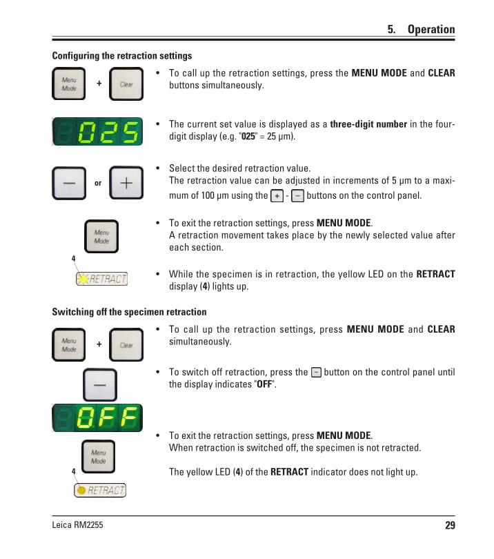
Configuring the retraction settings
• To call up the retraction settings, press the MENU MODE and CLEARbuttons simultaneously.
• The current set value is displayed as a three-digit number in the four-digit display (e.g. "025" = 25 µm).
• Select the desired retraction value.The retraction value can be adjusted in increments of 5 µm to a maxi-mum of 100 µm using the - buttons on the control panel.
• To exit the retraction settings, press MENU MODE.A retraction movement takes place by the newly selected value aftereach section.
• While the specimen is in retraction, the yellow LED on the RETRACTdisplay (4) lights up.
Switching off the specimen retraction
• To call up the retraction settings, press MENU MODE and CLEARsimultaneously.
• To switch off retraction, press the button on the control panel untilthe display indicates "OFF".
• To exit the retraction settings, press MENU MODE.When retraction is switched off, the specimen is not retracted.
The yellow LED (4) of the RETRACT indicator does not light up.
+
or
4
4
+
30 Instructions for Use V 1.6 RevA – 10/2011
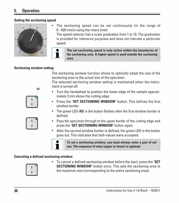
Setting the sectioning speed• The sectioning speed can be set continuously (in the range of
0 - 420 mm/s) using the rotary knob.The speed selector has a scale graduation from 1 to 10. The graduationis provided for reference purposes and does not indicate a particularspeed.
The set sectioning speed is only active within the boundaries ofthe sectioning area. A higher speed is used outside the sectioningarea.
Sectioning window settingThe sectioning window function allows to optimally adapt the size of thesectioning area to the actual size of the specimen.The selected sectioning window setting is maintained when the instru-ment is turned off.• Turn the handwheel to position the lower edge of the sample approxi-
mately 3 mm above the cutting edge.• Press the "SET SECTIONING WINDOW" button. This defines the first
window border.• The green LED (43) in the button flashes after the first window border is
defined.• Pass the specimen through to the upper border of the cutting edge and
press the "SET SECTIONING WINDOW" button again.• After the second window border is defined, the green LED in the button
goes out. This indicates that both values were accepted.
To set a sectioning window, you must always enter a pair of val-ues. The sequence of entry (upper or lower) is optional.
Canceling a defined sectioning window• To cancel a defined sectioning window before the start, press the "SET
SECTIONING WINDOW" button once. This sets the sectioning area tothe maximum size (corresponding to the entire sectioning area).
5. Operation
43
31Leica RM2255
5. Operation
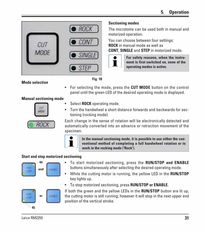
Mode selection• For selecting the mode, press the CUT MODE button on the control
panel until the green LED of the desired operating mode is displayed.Manual sectioning mode
• Select ROCK operating mode.• Turn the handwheel a short distance forwards and backwards for sec-
tioning (rocking mode).Each change in the sense of rotation will be electronically detected andautomatically converted into an advance or retraction movement of thespecimen.
In the manual sectioning mode, it is possible to use either the con-ventional method of completing a full handwheel rotation or towork in the rocking mode ('Rock').
Start and stop motorized sectioning• To start motorized sectioning, press the RUN/STOP and ENABLE
buttons simultaneously after selecting the desired operating mode.• While the cutting motor is running, the yellow LED in the RUN/STOP
key lights up.• To stop motorized sectioning, press RUN/STOP or ENABLE.If both the green and the yellow LEDs in the RUN/STOP button are lit up,the cutting motor is still running; however it will stop in the next upper endposition of the vertical stroke.
Sectioning modesThe microtome can be used both in manual andmotorized operation.You can choose between four settings:ROCK in manual mode as well asCONT, SINGLE and STEP in motorized mode.
For safety reasons, when the instru-ment is first switched on, none of theoperating modes is active.
and
or
44
45
Fig. 18

32 Instructions for Use V 1.6 RevA – 10/2011
Motorized sectioningIn motorized operation, you can choose between three operating modes:CONT = continuous stroke,SINGLE = single strokeSTEP = step stroke
CONT (continuous stroke) operating mode• Select CONT operating mode.After beginning the sectioning process, sectioning continues until theprocess is stopped by pressing RUN/STOP or ENABLE.The specimen then stops automatically in the next upper end position ofthe vertical stroke.
SINGLE (single stroke) operating mode• Select SINGLE operating mode.After starting sectioning, a single sectioning stroke is completed.The specimen then stops automatically in the upper end position of thevertical stroke.
In motorized sectioning mode, the sectioning process can be start-ed and stopped with the foot switch (optional accessory) instead ofthe RUN/STOP and ENABLE buttons.See chapter "Foot switches" (p. 32).
STEP (step stroke) operating mode• Select STEP (step stroke) operating mode.After starting the sectioning process, the specimen is moved as long asthe keys are held depressed (or as long as the foot pedal is pressed).
If the buttons or the foot switch are released, the specimen stops auto-matically.
5. Operation
and

33Leica RM2255
5. Operation
Indication of remaining horizontal feed
The visible and audible remaining feed indica-tion feature informs the user during trimmingand sectioning when a remaining feed of ap-proximately 1 mm is available before the frontlimit is reached.The yellow LED (41) in the COARSE FEED buttonlights up from the beginning of the remainingfeed. In addition, an acoustic signal is heard forapprox. 2 seconds.The sectioning process is interrupted and theobject head stops in the upper end position.From this point on, a remaining feed of approx.1 mm is available.In the remaining feed area, no more objectfeeding to the knife is possible using the coarsefeed buttons.
• Restart motorized sectioning.The yellow LED (41) in the COARSE FEED button lights up.
• When the front end position is reached, the sectioning process stopsautomatically.
• Upon restart, no more feed motion takes place.• You can continue to work on the specimen by pressing the corre-
sponding coarse feed button in the rear end position (HOME) and con-tinuing with sectioning.
To do so, you must press TRIM/SECT to switch to trimming mode,as otherwise, you cannot use the coarse feed.If the object head is already in the remaining feed range when theinstrument is switched on, an additional acoustic signal is heardafter the software version is displayed.
• You can continue to work on the specimen by moving it back a shortdistance using the coarse feed buttons (set trimming mode!).
• The STEP function is disabled in the remaining feed range.
Fig. 19
Object head
and
HOME
41
or
Remaining travel
Total feed

34 Instructions for Use V 1.6 RevA – 10/2011
Foot switch (optional accessory)The foot switch can be used to control the motorized sectioning process.It also has a function that is similar to the emergency stop function.
Caution!In addition to the foot switch, all control panel functions and allbuttons on the instrument continue to be active.
• Using the CUT MODE button, select the desired operating mode, CONT,SINGLE or STEP, on the control panel (Fig. 18).
CONT (continuous stroke) operating mode• Press the foot switch once briefly to start motorized sectioning.
If the foot switch remains pressed for longer than half a second,the specimen stops in the next upper end position.
• Press the foot switch again to stop it.The specimen stops in the next upper end position.
SINGLE (single stroke) operating mode• Press the foot switch once briefly to start motorized sectioning. After
every step, the specimen stops automatically in the upper end position.
STEP (step stroke) operating mode• Press down the foot switch to start the sectioning process. The speci-
men is now moved for as long as the foot switch is depressed.• If the foot switch is released, the specimen remains stationary in the
position that it has reached.
How to activate the emergency stop function• Press the foot switch strongly to activate the emergency stop function.
Sectioning stops immediately.The red LED in the E-STOP field on the instrument (Fig. 14) is lit up aslong as the foot switch remains depressed.
• To continue, restart the sectioning process using the foot switch. Theoperating mode remains unchanged.
5. Operation

35Leica RM2255
In the quick clamping device of the directional specimen holder fixture, all specimen clampsavailable as optional accessories can be used (implemented).
Directional fixture for specimen clamps
Orienting the specimen
Specimen blocks must not be orientedduring the retraction phase!If a block is oriented during retraction,the block will advance by the retrac-tion value PLUS the selected sectionthickness before the next section.This may cause damage to both speci-men and knife!
• Raise the object head to the upper end posi-tion and activate the handwheel lock.
• To release the clamp, turn the eccentric le-ver (29) forwards.
• Turn setscrew (30) to orient the specimen innorth-south direction. Turn setscrew (31) toorient the specimen in east-west direction.Each complete turn of the screw inclines thespecimen by 2°. A total of 4 complete turns =8° are possible in every direction. The accu-racy is approximately ± 0.5°.For ease of estimation, there is a white markon the handle and a click stops that is no-ticeable during turning.
• To lock the current orientation, turn the ec-centric lever (29) backwards.
Fig. 20
When the large standard specimenclamp (50 x 55 mm) is used, the speci-men orientation of 8° in north-southdirection is no longer possible.The usable angle is only about 4° inthis case.
Display of the zero positionFor better display of the zero position, the orien-tation has two red indicators (32).When both indicators are visible and both set-screws (30,31) are in zero position at the sametime (notch point, white marking on " ") thespecimen is in zero position.
5. Operation
The directional specimen holder fixture may beexchanged for a non-directional fixture (option-al accessory).
The object orientation allows for simple positioncorrection of the specimen surface when thespecimen is clamped into place.
32
30 32
31
29

36 Instructions for Use V 1.6 RevA – 10/2011
5. Operation
Fine adjustment of the force balanceIf another accessory of a different weight ismounted on the object head (33), you mustcheck whether it is necessary to readjust theforce balance.Checking the correct setting:• Attach the new accessory and clamp the
specimen.• Set the object head to half the height of the
vertical travel range by turning the hand-wheel (Fig. 21).
If the object head remains in this exact position,the setting is correct.If the object head moves, i.e. it is raised or low-ered, fine adjustment is necessary.
Failure to adjust the force balancemay result in injury while working.
The force balance is adjusted using the screw(34), which can be accessed by removing thesection waste tray on the bottom of the baseplate of the microtome. Use the Allen key pro-vided, size 5 (with handle!) for the adjustment.
• If the object head moves downwards, turn thescrew approx. 1/2 clockwise.
• If the object head moves upwards, turn thescrew (34) approx. 1/2 turn counterclock-wise.
• Continue this procedure until the objecthead no longer moves once released.
Fig. 21
Fig. 22
33
34
Important!Never turn thescrew morethan 1/2 turn ata time.
37Leica RM2255
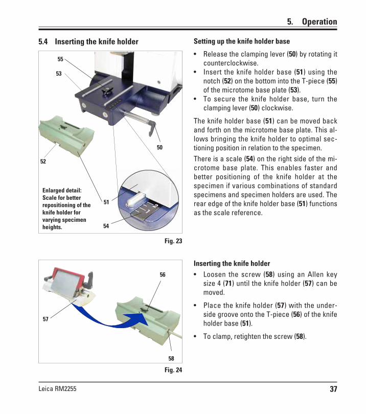
Setting up the knife holder base
• Release the clamping lever (50) by rotating itcounterclockwise.
• Insert the knife holder base (51) using thenotch (52) on the bottom into the T-piece (55)of the microtome base plate (53).
• To secure the knife holder base, turn theclamping lever (50) clockwise.
The knife holder base (51) can be moved backand forth on the microtome base plate. This al-lows bringing the knife holder to optimal sec-tioning position in relation to the specimen.There is a scale (54) on the right side of the mi-crotome base plate. This enables faster andbetter positioning of the knife holder at thespecimen if various combinations of standardspecimens and specimen holders are used. Therear edge of the knife holder base (51) functionsas the scale reference.
Fig. 23
55
50
51
52
53
5. Operation
5.4 Inserting the knife holder
Inserting the knife holder• Loosen the screw (58) using an Allen key
size 4 (71) until the knife holder (57) can bemoved.
• Place the knife holder (57) with the under-side groove onto the T-piece (56) of the knifeholder base (51).
• To clamp, retighten the screw (58).
Fig. 24
56
57
58
Enlarged detail:Scale for betterrepositioning of theknife holder forvarying specimenheights. 54
38 Instructions for Use V 1.6 RevA – 10/2011
5. Operation
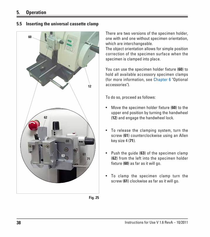
There are two versions of the specimen holder,one with and one without specimen orientation,which are interchangeable.The object orientation allows for simple positioncorrection of the specimen surface when thespecimen is clamped into place.
You can use the specimen holder fixture (60) tohold all available accessory specimen clamps(for more information, see Chapter 6 "Optionalaccessories").
To do so, proceed as follows:
• Move the specimen holder fixture (60) to theupper end position by turning the handwheel(12) and engage the handwheel lock.
• To release the clamping system, turn thescrew (61) counterclockwise using an Allenkey size 4 (71).
• Push the guide (63) of the specimen clamp(62) from the left into the specimen holderfixture (60) as far as it will go.
• To clamp the specimen clamp turn thescrew (61) clockwise as far as it will go.
Fig. 25
5.5 Inserting the universal cassette clamp
7163
62
60
12
61
60

39Leica RM2255
5. Operation
• The index marks (0°, 5° and 10°) for adjust-ment of the clearance angle (59.1) are locat-ed on the right side of the knife holder (57).
• There is also an index mark (59.2) on theright side of the knife holder basis (51) whichserves as a reference point when adjustingthe clearance angle.
• Loosen the screw (58) using an Allen keysize 4 (71) until the knife holder (57) can bemoved.
• Move the knife holder until the index mark ofthe desired clearance angle coincides withthe reference line on the knife holder base.Example:The enlarged detail illustration shows aclearance angle setting of 5°.
The recommended clearance anglesetting for knife holder E ranges froma minimum of 2.5° to 5°.
• Hold down the knife holder in this positionand retighten the screw (58) for clamping.
5.6 Adjusting the clearance angle
Fig. 26
51
58
57
59.1
59.2
Enlarged detail:Index marks forclearance anglesetting
71

40 Instructions for Use V 1.6 RevA – 10/2011
5. Operation
5.7 Clamping the specimen
Always clamp the specimen block BEFORE clamping the knife.Lock the handwheel and cover the knife edge with the knife guardprior to any manipulation of knife or specimen, prior to changingthe specimen block and during all work breaks!
• Rotate the handwheel until the specimen clamp is in the uppermostposition.
• Activate the handwheel lock by allowing the handwheel handle to lockin place and then activate the brake.
• Insert a specimen block into the specimen clamp.
A detailed description for inserting the specimen into variousspecimen clamps and specimen holders is provided in Chapter 6"Optional accessories".
5.8 Clamping the knife/disposable blade
Be very careful when handling microtome knives or blades. Thecutting edge is extremely sharp and can cause severe injury!
10
99a
• Fold knife guard (9) downward.
• To insert the blade, flip the right clamping le-ver (10) forward and down.
Fig. 27
41Leica RM2255
5. Operation
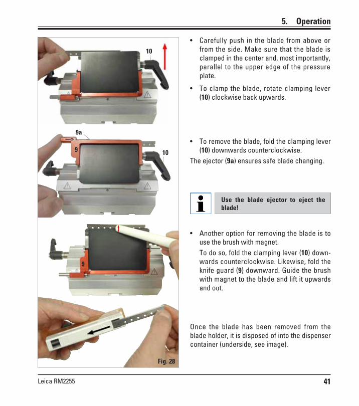
• Carefully push in the blade from above orfrom the side. Make sure that the blade isclamped in the center and, most importantly,parallel to the upper edge of the pressureplate.
• To clamp the blade, rotate clamping lever(10) clockwise back upwards.
Fig. 28
10
10
9a
9• To remove the blade, fold the clamping lever
(10) downwards counterclockwise.The ejector (9a) ensures safe blade changing.
Use the blade ejector to eject theblade!
Once the blade has been removed from theblade holder, it is disposed of into the dispensercontainer (underside, see image).
• Another option for removing the blade is touse the brush with magnet.To do so, fold the clamping lever (10) down-wards counterclockwise. Likewise, fold theknife guard (9) downward. Guide the brushwith magnet to the blade and lift it upwardsand out.
9

42 Instructions for Use V 1.6 RevA – 10/2011
5.9.2 Trimming in motorized sectioning mode
The handle of the handwheel must always be centered while inmotorized sectioning mode. Always turn the handwheel evenly inclockwise direction; otherwise, the brake will not work properly.
• Use the TRIM/SECT key to select the trim mode.
• Set the desired trim section thickness.
• If necessary, set the sectioning window.
Always set the sectioning speed according to the hardness of thespecimen! For hard specimens, always select a slow speed.
• Using the rotary knob, set the appropriate sectioning speed.• Using the CUT MODE button, select the CONT operating mode (contin-
uous stoke).• Deactivate the handwheel lock and release the brake.• Start motorized sectioning and trim the sample.• Terminate trimming when the desired sectioning surface and depth
have been reached.
5. Operation
5.9 Trimming the specimen5.9.1 Trimming in manual sectioning mode
• Use the TRIM/SECT key to select the trim mode.• Set the desired trim section thickness.• Deactivate the handwheel lock and release the brake.• In TRIM mode, use the coarse feed buttons to move the sample
against the knife/blade.• Trim the sample by turning the handwheel
or• Using the CUT MODE key, select the ROCK operating mode and cut the
specimen with forward and backward motions of the handwheel.• Terminate trimming when the desired sectioning surface and depth
have been reached.During fast manual trimming, do not put your fingers between thespecimen and knife. The handwheel continues turning after it is re-leased and can cause injuries.
+
43Leica RM2255
5. Operation
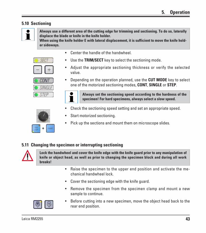
5.10 Sectioning
Always use a different area of the cutting edge for trimming and sectioning. To do so, laterallydisplace the blade or knife in the knife holder.When using the knife holder E with lateral displacement, it is sufficient to move the knife hold-er sideways.
• Center the handle of the handwheel.
• Use the TRIM/SECT key to select the sectioning mode.
• Adjust the appropriate sectioning thickness or verify the selectedvalue.
• Depending on the operation planned, use the CUT MODE key to selectone of the motorized sectioning modes, CONT, SINGLE or STEP.
Always set the sectioning speed according to the hardness of thespecimen! For hard specimens, always select a slow speed.
• Check the sectioning speed setting and set an appropriate speed.
• Start motorized sectioning.
• Pick up the sections and mount them on microscope slides.+
5.11 Changing the specimen or interrupting sectioning
Lock the handwheel and cover the knife edge with the knife guard prior to any manipulation ofknife or object head, as well as prior to changing the specimen block and during all workbreaks!
• Raise the specimen to the upper end position and activate the me-chanical handwheel lock.
• Cover the sectioning edge with the knife guard.
• Remove the specimen from the specimen clamp and mount a newsample to continue.
• Before cutting into a new specimen, move the object head back to therear end position.
44 Instructions for Use V 1.6 RevA – 10/2011
6. Optional accessories
6.1 Assembly for specimen holder fixture
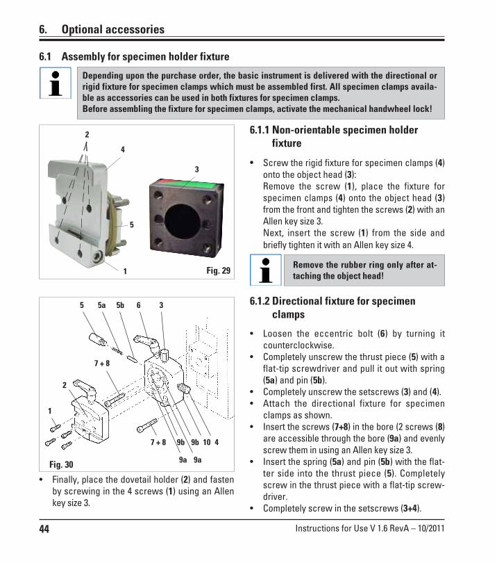
Depending upon the purchase order, the basic instrument is delivered with the directional orrigid fixture for specimen clamps which must be assembled first. All specimen clamps availa-ble as accessories can be used in both fixtures for specimen clamps.Before assembling the fixture for specimen clamps, activate the mechanical handwheel lock!
6.1.1 Non-orientable specimen holderfixture
• Screw the rigid fixture for specimen clamps (4)onto the object head (3):Remove the screw (1), place the fixture forspecimen clamps (4) onto the object head (3)from the front and tighten the screws (2) with anAllen key size 3.Next, insert the screw (1) from the side andbriefly tighten it with an Allen key size 4.
Remove the rubber ring only after at-taching the object head!Fig. 291
2
4
5
3
6.1.2 Directional fixture for specimenclamps
• Loosen the eccentric bolt (6) by turning itcounterclockwise.
• Completely unscrew the thrust piece (5) with aflat-tip screwdriver and pull it out with spring(5a) and pin (5b).
• Completely unscrew the setscrews (3) and (4).• Attach the directional fixture for specimen
clamps as shown.• Insert the screws (7+8) in the bore (2 screws (8)
are accessible through the bore (9a) and evenlyscrew them in using an Allen key size 3.
• Insert the spring (5a) and pin (5b) with the flat-ter side into the thrust piece (5). Completelyscrew in the thrust piece with a flat-tip screw-driver.
• Completely screw in the setscrews (3+4).
Fig. 30
1
2
35b5a5 6
4
7 + 8
7 + 8 9b 9b
9a 9a
10
• Finally, place the dovetail holder (2) and fastenby screwing in the 4 screws (1) using an Allenkey size 3.

45Leica RM2255
6.1.3 Fine-directionalspecimen holder fixture
• Before the fine-directional fixture for speci-men clamps can be mounted, loosen4 screws (10) (Allen key size 3) and carefullyremove the fixture for specimen clamps fromthe baseplate (9).
Fig. 31
10
11
• Using the 4 supplied screws (11) and theAllen key size 3, fasten the baseplate to theobject head (12).
11
• Now, screw the fine-directional fixture forspecimen clamps with the 4 screws (10) andthe Allen key size 3 onto the object head.
If the fine-directional fixture for speci-men clamps is not used, retain thebaseplate and 4 screws (11) togetherwith the fine-directional fixture forspecimen clamps!
9
12
6. Optional accessories
46 Instructions for Use V 1.6 RevA – 10/2011
6. Optional accessories
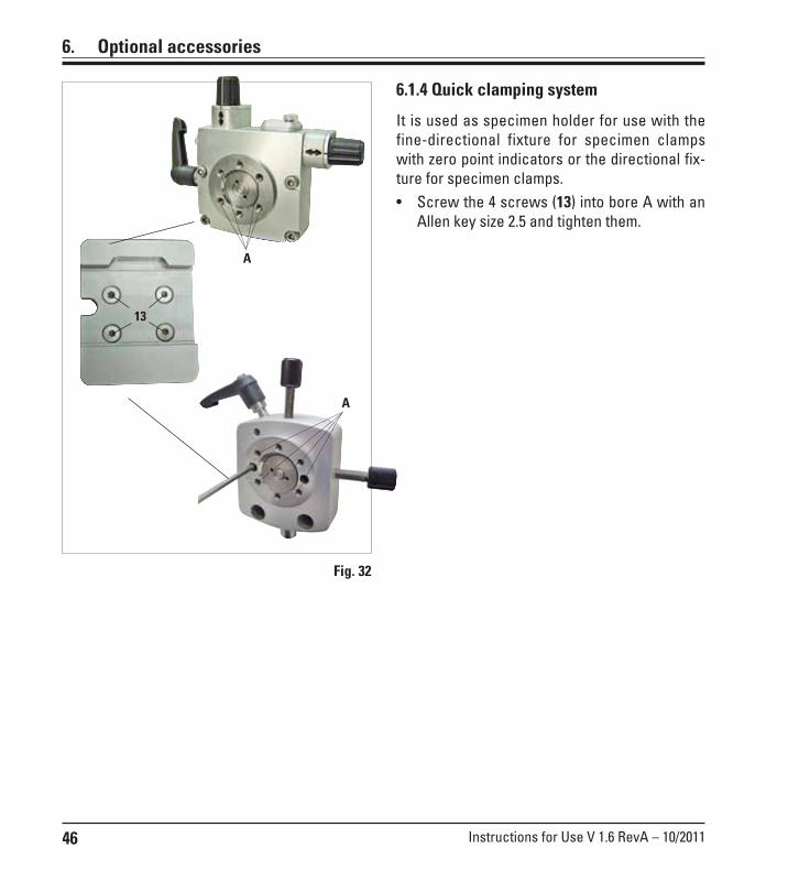
6.1.4 Quick clamping system
It is used as specimen holder for use with thefine-directional fixture for specimen clampswith zero point indicators or the directional fix-ture for specimen clamps.• Screw the 4 screws (13) into bore A with an
Allen key size 2.5 and tighten them.
Fig. 32
13
A
A
47Leica RM2255
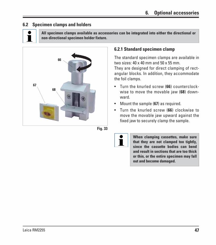
6.2.1 Standard specimen clamp
The standard specimen clamps are available intwo sizes: 40 x 40 mm and 50 x 55 mm.They are designed for direct clamping of rect-angular blocks. In addition, they accommodatethe foil clamps.
• Turn the knurled screw (66) counterclock-wise to move the movable jaw (68) down-ward.
• Mount the sample (67) as required.• Turn the knurled screw (66) clockwise to
move the movable jaw upward against thefixed jaw to securely clamp the sample.
6.2 Specimen clamps and holders
All specimen clamps available as accessories can be integrated into either the directional ornon-directional specimen holder fixture.
Fig. 33
66
6867
6. Optional accessories
When clamping cassettes, make surethat they are not clamped too tightly,since the cassette bodies can bendand result in sections that are too thickor thin, or the entire specimen may fallout and become damaged.
48 Instructions for Use V 1.6 RevA – 10/2011
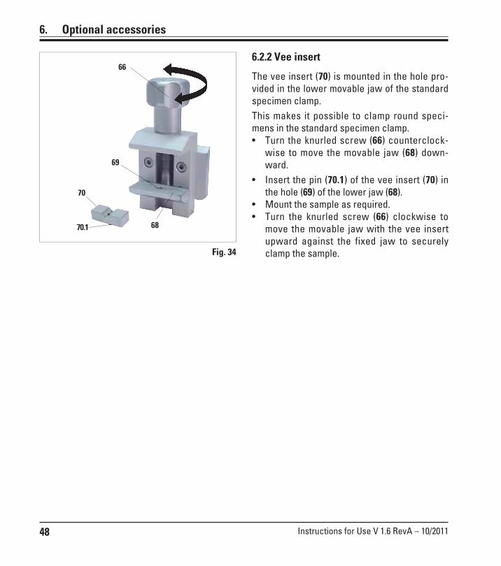
6.2.2 Vee insert
The vee insert (70) is mounted in the hole pro-vided in the lower movable jaw of the standardspecimen clamp.This makes it possible to clamp round speci-mens in the standard specimen clamp.• Turn the knurled screw (66) counterclock-
wise to move the movable jaw (68) down-ward.
• Insert the pin (70.1) of the vee insert (70) inthe hole (69) of the lower jaw (68).
• Mount the sample as required.• Turn the knurled screw (66) clockwise to
move the movable jaw with the vee insertupward against the fixed jaw to securelyclamp the sample.Fig. 34
70
66
69
70.1 68
6. Optional accessories

49Leica RM2255
6. Optional accessories
Clamping of foil pieces• Move the movable jaw (74) to the right as re-
quired by turning the set screw with an Allenkey size 4 (71).
• Place the foil (72) between the movable jaw(74) and the fixed jaw (73).
• To clamp the foil, screw the movable jaw(74) against the fixed jaw (73) by using theAllen key.
• Insert the foil clamp (75) in the standardspecimen clamp as shown.
• Turn the knurled screw (66) clockwise toclamp the foil clamp in the standard speci-men clamp.
6.2.3 Foil clamp type 1The foil clamp type 1 is appropriate both forclamping very small foil pieces and flat, angularsamples. It is mounted in the standard speci-men clamp.
Clamping of flat, angular samplesTo clamp angular samples, replace the longset screw (76) with the short set screw (77)provided with the foil clamp.• Unscrew the long set screw (76) to the left
with an Allen key size 4 (71).• Screw the short set screw (77) in the hole.• Place the sample (67) between the movable
jaw (74) and the fixed jaw (73).• To clamp the sample, screw the movable
jaw (74) by turning the set screw (77) againstthe fixed jaw (73).
• Insert the foil clamp in the standard speci-men clamp as shown.
• Turn the knurled screw (66) clockwise toclamp the foil clamp in the standard speci-men clamp.
Fig. 35
Fig. 36
66
74
72
75
71
73
76
77
67
7473
50 Instructions for Use V 1.6 RevA – 10/2011
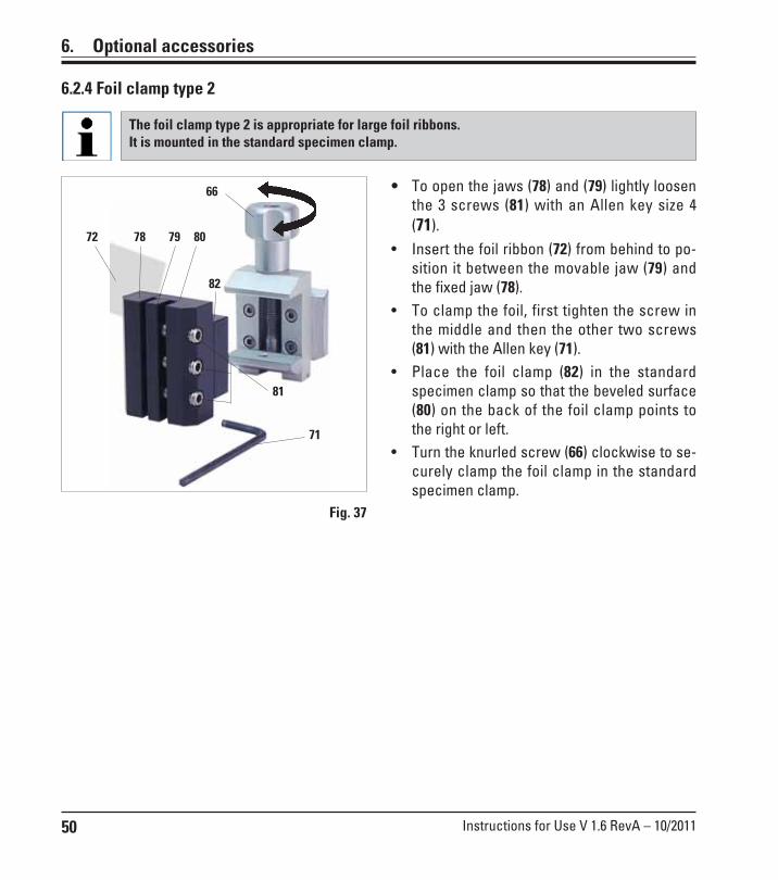
• To open the jaws (78) and (79) lightly loosenthe 3 screws (81) with an Allen key size 4(71).
• Insert the foil ribbon (72) from behind to po-sition it between the movable jaw (79) andthe fixed jaw (78).
• To clamp the foil, first tighten the screw inthe middle and then the other two screws(81) with the Allen key (71).
• Place the foil clamp (82) in the standardspecimen clamp so that the beveled surface(80) on the back of the foil clamp points tothe right or left.
• Turn the knurled screw (66) clockwise to se-curely clamp the foil clamp in the standardspecimen clamp.
6.2.4 Foil clamp type 2
The foil clamp type 2 is appropriate for large foil ribbons.It is mounted in the standard specimen clamp.
Fig. 37
6. Optional accessories
71
72 7978
66
81
80
82

51Leica RM2255
65
60
Fig. 38
Prior to sectioning, laboratory person-nel MUST check that the cassette isseated securely in the universal cas-sette clamp.
• Push the lever (60) forwards.• Mount the cassette (65) horizontally or verti-
cally as required.• To clamp the cassette, release the lever (60).
6.2.5 Universal cassette clamp
6. Optional accessories
Leica/Surgipath cassettes withminimum dimensions of 39.8 x 28 mm and maximum dimensions of 40.9 x 28.8 mm can beclamped horizontally as well as vertically in the Universal Cassette Clamp (UCC).
The use of other - particularly thin-walled - cassettes can lead to deformation of the cassette orother problems with the clamping system. If, while clamping the cassette, the user determinesthat it is not stably clamped into place, an alternative tensioning clamp must be used.
When using cassettes whose lid is molded on make sure that the broken edge left by removingthe lid does not prevent the specimen from being securely clamped – if necessary, thespecimen must be clamped horizontally.
Before clamping the cassette into the universal cassette clamp, remove excess wax on theoutside of the cassette to ensure that the cassette clamps in securely.
Wax deposits on the outside of the cassette can make the universal cassette clamp dirty. Thedirt prevents the cassette from clamping in securely and can lead to sections being too thick orthin, chattering within the section and in the worst-case scenario, damage to the specimen.Prior to sectioning, the user has to verify that the specimen is clamped securely and, ifnecessary, remove wax deposits from the universal cassette clamp according to thespecifications in Chapter 8.1 "Cleaning and maintenance – Universal cassette clamp".

52 Instructions for Use V 1.6 RevA – 10/2011
• To mount the required insert (89.1-3) turn theclamping ring (90) counterclockwise and re-move it.
• Place the required insert into the tensionring (90) and screw the tension ring onto thethread (91) by turning it clockwise.
• Mount the sample (67) and fix by turning theclamping ring (90) clockwise.
• To orient the inserted sample, insert the pin(92) into the bore (93) and rotate it counter-clockwise to release the clamp. You cannow rotate the specimen so that the sideyou want faces upwards.
• To lock it in the position you have chosen,tighten the pin (92) by turning it clockwise.
6.2.6 Round specimen holder
The holder for round specimens is designed to accommodate cylindrical samples.Inserts for specimens of 6, 15 and 25 mm diameter are available.
Fig. 40
6. Optional accessories
89.3
67
89.1
93
90
89.2
91
92
Universal cassette clamp, ice-cooled
Fig. 39
a
b
Use the ice-cooled UCC with the non-directional specimen holder fixtureonly!
For use with standard cassettes with dimensionsthat are 38.9 x 28mm at minimum and 40.9 x28.8mm at maximum.
• Ice cubes can be made using the includedParaflex mold (a).
• Quick clamping system (b) refer to Chapter 6.1.4.
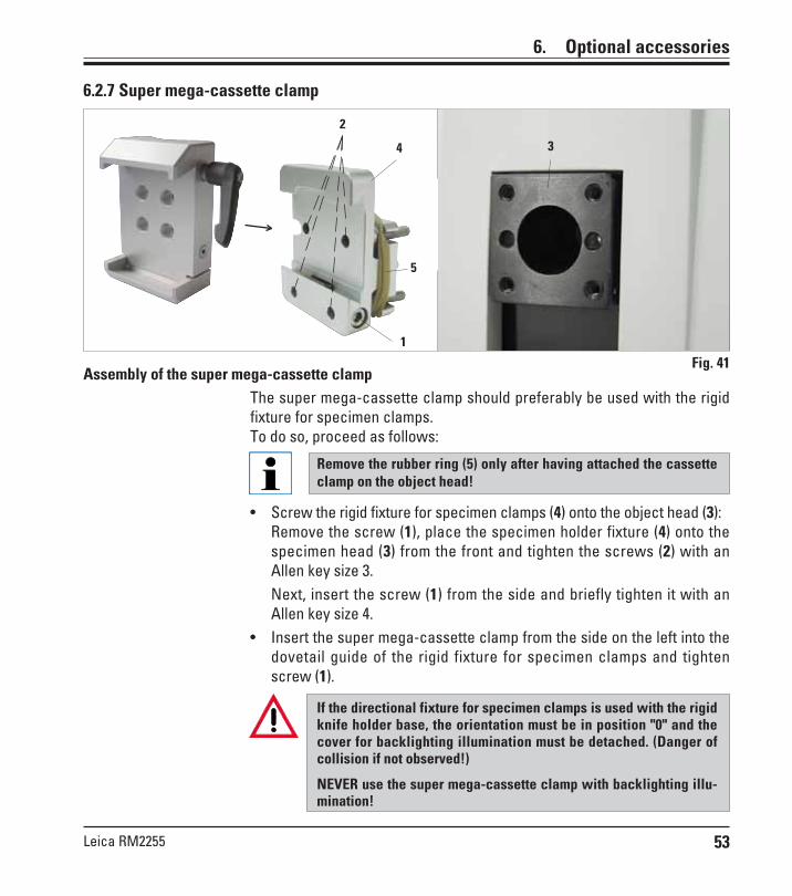
53Leica RM2255
6. Optional accessories
Assembly of the super mega-cassette clampThe super mega-cassette clamp should preferably be used with the rigidfixture for specimen clamps.To do so, proceed as follows:
• Screw the rigid fixture for specimen clamps (4) onto the object head (3):Remove the screw (1), place the specimen holder fixture (4) onto thespecimen head (3) from the front and tighten the screws (2) with anAllen key size 3.Next, insert the screw (1) from the side and briefly tighten it with anAllen key size 4.
• Insert the super mega-cassette clamp from the side on the left into thedovetail guide of the rigid fixture for specimen clamps and tightenscrew (1).
If the directional fixture for specimen clamps is used with the rigidknife holder base, the orientation must be in position "0" and thecover for backlighting illumination must be detached. (Danger ofcollision if not observed!)
NEVER use the super mega-cassette clamp with backlighting illu-mination!
6.2.7 Super mega-cassette clamp
Fig. 411
2
34
5
Remove the rubber ring (5) only after having attached the cassetteclamp on the object head!
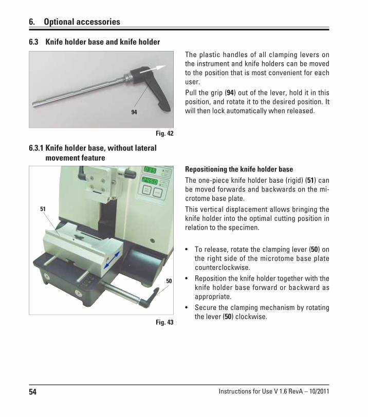
54 Instructions for Use V 1.6 RevA – 10/2011
6. Optional accessories
6.3 Knife holder base and knife holder
Repositioning the knife holder baseThe one-piece knife holder base (rigid) (51) canbe moved forwards and backwards on the mi-crotome base plate.This vertical displacement allows bringing theknife holder into the optimal cutting position inrelation to the specimen.
• To release, rotate the clamping lever (50) onthe right side of the microtome base platecounterclockwise.
• Reposition the knife holder together with theknife holder base forward or backward asappropriate.
• Secure the clamping mechanism by rotatingthe lever (50) clockwise.
The plastic handles of all clamping levers onthe instrument and knife holders can be movedto the position that is most convenient for eachuser.Pull the grip (94) out of the lever, hold it in thisposition, and rotate it to the desired position. Itwill then lock automatically when released.
6.3.1 Knife holder base, without lateralmovement feature
Fig. 42
Fig. 43
51
50
94

55Leica RM2255
6. Optional accessories
Prior to inserting the blade, both knifeholder and knife holder base musthave been installed on the instrument!
Inserting the blades, knife holder E and E-TC
• Fold knife guard (9) downward.
• To insert the blade, flip the right clamping le-ver (10) forward and down.
• Carefully insert the blade from the side.Make sure that the blade is clamped parallelto the upper edge of the pressure plate.
• To clamp the blade, rotate clamping lever(10) back upwards.
6.3.2 Knife holder E/E-TC
The knife holder E is designed for conventional disposable blades from all current manufactur-ers. It is available in two models: one for low profile, blades and one for high profile, blades.The knife holder has a lateral displacement, so that the entire width of the blade can be used.The ejector (9a) ensures safe blade changing.
Fig. 45
9
11 10
Fig. 44
Knife holder E-TC
Knife holder E
The knife holder E-TC is designed forthe Leica TC-65 tungsten carbideblades.
The clamping levers on the knife hold-er are not interchangeable. The twoclamping levers (10, 11) must remainin the position shown at all times, asotherwise isolated malfunctions of theknife holder can occur.Clamping lever for the blade (10) at theright, clamping lever for the lateraldisplacement (11) at the left.
9 10
9a

56 Instructions for Use V 1.6 RevA – 10/2011
6. Optional accessories
Lateral displacement (only for knife holder E)The lateral displacement feature of the knifeholder base enables the use of the entire lengthof the blade, eliminating the need for readjust-ing the knife holder. The knife holder E consistsof a segment arch A (with lever (11)) and theclamp mount B (with lever (10) and ejector (13)).The extreme left and right positions as well asthe middle position are each marked with aclick stop.• To release the clamp, rotate the lever (11) on
the left side of the knife holder forwards.• Move the knife holder sideways.• To clamp, rotate the lever (11) back.Fig. 46
11
Note on the knife holder E:
The knife holder E is an important precision component, the quality andprecise adjustment of which have a lasting effect on the entire function ofthe microtome. In case of malfunctions or damages to the clamp mount, itis always required to replace the clamp mount, including the pertinentclamping lever.Leica Biosystems offers special prices for new clamp mounts in case ofdamages to the clamp mount after the warranty has expired.In this way, perfect function of the device can be ensured over the courseof many years.
Knife holder E
AB
10
To ensure a proper sectioning result, clampmount B must be securely clamped onto seg-ment arch A.The clamping is carried out using an eccentricat the lever (11). The clamping force is adjustedwith the setscrew (12) on the underside of thesegment arch. The setting of the clamping iscarried out so that the clamping lever can be ro-tated to the stop with constantly increasing re-sistance.
Setting of the clamping system of the clamp mount on the segment arch
12
Adjust the clamping with a 2.5 mm Allen key atthe grubscrew (12) so that the lever initially"slips" when the lever is activated. Continueturning the grubscrew (12) a little bit (approx. 1/4turn to the left or right), then check that the le-ver no longer "bars", but also does not jam"heavily".(The language CD features a short video film forthis purpose.)
13

57Leica RM2255
6. Optional accessories
Knife holder E with water bath for narrow-band and broad-band blades
Fig. 47
Knife holder E with water bath is available forboth low profile, and high profile, blades.The knife guard on knife holder E consists of ared foldaway handle (9). To cover the cuttingedge, fold the knife guard handle (9) upwardsas illustrated in the figure.
911 10
The clamping levers on the knife holder are not interchangeable. The two clamping levers(10 and 11) must remain in the position shown at all times, as otherwise isolated malfunctionsof the knife holder can occur.Clamping lever for the blade (10) at the right, clamping lever for the lateral displacement (11) atthe left.
UseFloating thin paraffin sections (for example, for subsequent immunostain-ing procedures) on the surface of the water. Flat paraffin sections can beremoved from the surface of the water using glass slides.
The vessel is filled with water up to the blade.After trimming, remove the section waste fromthe tray and create the sections to be prepared.The sections floating on the surface of the wa-ter can be removed using the glass slide.
Fig. 48
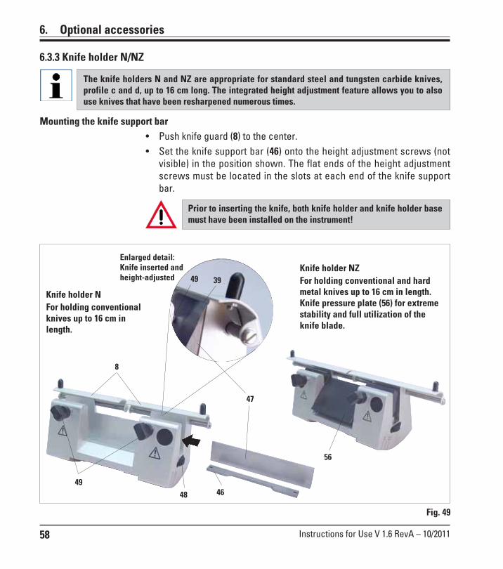
58 Instructions for Use V 1.6 RevA – 10/2011
6. Optional accessories
6.3.3 Knife holder N/NZ
The knife holders N and NZ are appropriate for standard steel and tungsten carbide knives,profile c and d, up to 16 cm long. The integrated height adjustment feature allows you to alsouse knives that have been resharpened numerous times.
Fig. 49
Enlarged detail:Knife inserted andheight-adjusted
Mounting the knife support bar• Push knife guard (8) to the center.• Set the knife support bar (46) onto the height adjustment screws (not
visible) in the position shown. The flat ends of the height adjustmentscrews must be located in the slots at each end of the knife supportbar.
Prior to inserting the knife, both knife holder and knife holder basemust have been installed on the instrument!
Knife holder NFor holding conventionalknives up to 16 cm inlength.
Knife holder NZFor holding conventional and hardmetal knives up to 16 cm in length.Knife pressure plate (56) for extremestability and full utilization of theknife blade.
8
46
47
4948
49 39
56

59Leica RM2255
6. Optional accessories
Inserting the knife
• Rotate the knurled nuts (48) on the right and left of the knife holderforward in opposite directions, lowering the knife support bar to thelowest possible position, thus ensuring that the knife edge will not bedamaged when inserting the knife.
• Unscrew the clamping screws (49) as far out as possible (rotate coun-terclockwise).
• Hold the knife (47) at the knife base and carefully insert it in the holderfrom the side as shown with the cutting edge facing upward.
Knife height adjustment
When adjusting the clearance angle, the knife edge should be positionedas exactly as possible in the actual center of rotation of the knife holder.The lay-on edge (39) of the rear clamping chucks serves as a referenceposition for correct knife height adjustment. The knife edge should be par-allel with the locating edges.• Rotate the knurled nuts (48) uniformly and backwards until the knife
blade is parallel to the lay-on edge (39) (see detailed illustration) of therear clamping chucks.
• To clamp the knife (47) evenly screw the two knife clamping screws(49) inward (rotate clockwise).
Lateral repositioning of the knife
• Push knife guard (8) to the center.• Loosen the clamping screws (49) by turning them counterclockwise.• Push the knife (47) to the left or right as required.• To clamp the knife (47), always tighten the clamping screw (49) first
which is located on the side to which the knife has been repositionedby turning it clockwise.

60 Instructions for Use V 1.6 RevA – 10/2011
6. Optional accessories
6.4 Blades/knives
6.4.1 Disposable bladesDisposable blades - narrow band (819)80 x 8 x 0.25 mm01 Packages of 50 pcs. .................... 14 0358 3892510 Packages of 50 pcs. .................... 14 0358 38382
Disposable blades – high-profile (818)80 x 14 x 0.317 mm01 Packages of 50 pcs. .................... 14 0358 3892610 Packages of 50 pcs. .................... 14 0358 38383
Fig. 50
Fig. 51
6.4.2 KnifeKnife 16 cm – profile c – steelKnife, 16 cm long, profile c (ground on bothsides, for paraffin and frozen sections)Note: Knife case 14 0213 11140 includedOrder No. ............................................14 0216 07100
Knife 12 cm profile c - steelKnife, 12 cm long, profile cNote: Knife case 14 0213 11140 includedOrder No. ............................................14 0216 07092
Fig. 52
Profile

61Leica RM2255
6. Optional accessories
Knife 16 cm, profile d – steelKnife, 16 cm long, profile dNote: Knife case 14 0213 11140 includedOrder No. ............................................ 14 0216 07132
Knife 12 cm, profile d – steelKnife, 12 cm long, profile dNote: Knife case 14 0213 11140 includedOrder No. ............................................ 14 0216 07130
Knife, 16 cm, profile d, tungsten carbideKnife, 16 cm long, tungsten carbide, profile dNote: Knife case 14 0213 11140 includedOrder No. ............................................ 14 0216 04813
Knife 16 cm, profile c, tungsten carbideKnife, 16 cm, tungsten carbide, profile cNote: Knife case 14 0213 11140 includedOrder No. ............................................ 14 0216 04206
Knife caseVariable knife case (plastic),for 1 or 2 knives: 10 – 16 cm long(Hard metal or SM2500 knife: only for1 knife!)Order No. ............................................ 14 0213 11140
Serial numberhard metalknife
Fig. 53
Fig. 55
Fig. 54

62 Instructions for Use V 1.6 RevA – 10/2011
6. Optional accessories
The backlighting is inserted into thefront of the one-piece knife holderbase.
• Remove the two screws (1) using a slottedscrewdriver and then remove the coverplate (2).
• Insert the backlighting (3) in the recess atthe rear of the knife holder base.
• Connect the plug (4) of the backlighting tothe socket (5) on the microtome.
The backlighting illuminates once the micro-tome is turned on with the mains switch.
NEVER use the backlighting illumina-tion with the super mega-cassetteclamp!
Fig. 57
2
1
3
4
1
5
6.6 Backlighting
• Push the section waste tray (18) from thefront to the microtome base plate (53) until itis held in place by the two magnets (39) (onthe front of the microtome base plate).To remove the section waste tray, lift itslightly and pull it off towards the back.
Fig. 56
6.5 Section waste tray
53
18
39
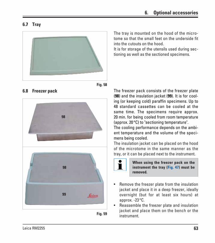
63Leica RM2255
6. Optional accessories
The freezer pack consists of the freezer plate(98) and the insulation jacket (99). It is for cool-ing (or keeping cold) paraffin specimens. Up to48 standard cassettes can be cooled at thesame time. The specimens require approx.20 min. for being cooled from room temperature(approx. 20 °C) to "sectioning temperature".The cooling performance depends on the ambi-ent temperature and the volume of the speci-mens being cooled.The insulation jacket can be placed on the hoodof the microtome in the same manner as thetray, or it can be placed next to the instrument.
When using the freezer pack on theinstrument the tray (Fig. 47) must beremoved.
• Remove the freezer plate from the insulationjacket and place it in a deep freezer, ideallyovernight (but for at least six hours) atapprox. -23 °C.
• Reassemble the freezer plate and insulationjacket and place them on the bench or theinstrument.
6.8 Freezer pack
Fig. 59
98
99
98
The tray is mounted on the hood of the micro-tome so that the small feet on the underside fitinto the cutouts on the hood.It is for storage of the utensils used during sec-tioning as well as the sectioned specimens.
Fig. 58
6.7 Tray

64 Instructions for Use V 1.6 RevA – 10/2011
6.9 Universal microscope carrier
1 - Baseplate with drilling (a)2 - Vertical column with size 8 cap screw (b) and
lock washer (c)3 - Horizontal arm with cross-member (d) and support
ring (e)4 - Support plate, large (for RM2235, RM2245 and
RM2255)5 - Support plate, small (for RM2265)6 - Allen key size 37 - 4 countersunk screws to install support plate8 - Allen key size 8
Unpack all accessories in the packageand check for completeness.
Assembling the universal microscopecarrier
1. Attach baseplate• Select the large (5) or small (4) support plate,
depending on the microtome to be used.• Attach the support plate to the baseplate with
the included 4 countersunk screws (7) usingthe Allen key size 3 (6).
1
bc
23
e
d
4
5
6
78
a
Fig. 60
Fig. 62
Fig. 61
6. Optional accessories
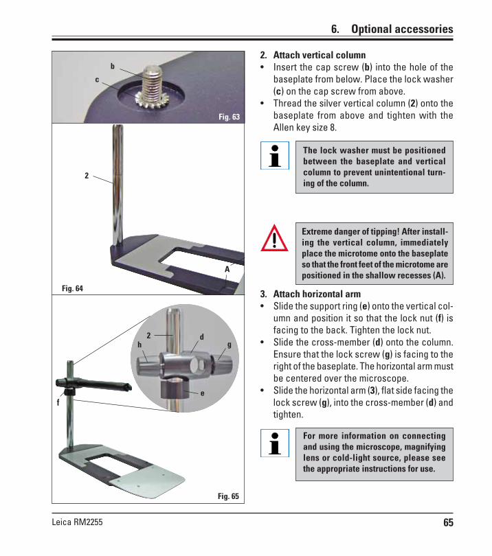
65Leica RM2255
2. Attach vertical column• Insert the cap screw (b) into the hole of the
baseplate from below. Place the lock washer(c) on the cap screw from above.
• Thread the silver vertical column (2) onto thebaseplate from above and tighten with theAllen key size 8.
The lock washer must be positionedbetween the baseplate and verticalcolumn to prevent unintentional turn-ing of the column.
A
Extreme danger of tipping! After install-ing the vertical column, immediatelyplace the microtome onto the baseplateso that the front feet of the microtome arepositioned in the shallow recesses (A).
3. Attach horizontal arm• Slide the support ring (e) onto the vertical col-
umn and position it so that the lock nut (f) isfacing to the back. Tighten the lock nut.
• Slide the cross-member (d) onto the column.Ensure that the lock screw (g) is facing to theright of the baseplate. The horizontal arm mustbe centered over the microscope.
• Slide the horizontal arm (3), flat side facing thelock screw (g), into the cross-member (d) andtighten.
For more information on connectingand using the microscope, magnifyinglens or cold-light source, please seethe appropriate instructions for use.
6. Optional accessories
Fig. 65
Fig. 64
Fig. 63
b
c
2
e
d2g
f
h
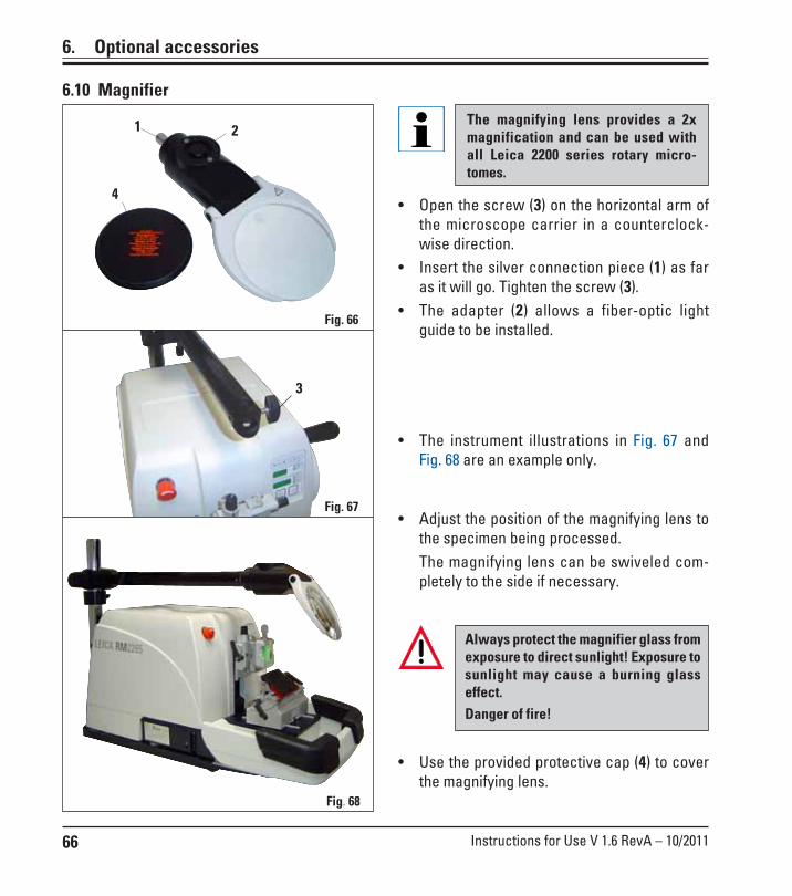
66 Instructions for Use V 1.6 RevA – 10/2011
6. Optional accessories
6.10 Magnifier
Fig. 66
Fig. 68
Fig. 67
• Open the screw (3) on the horizontal arm ofthe microscope carrier in a counterclock-wise direction.
• Insert the silver connection piece (1) as faras it will go. Tighten the screw (3).
• The adapter (2) allows a fiber-optic lightguide to be installed.
• Adjust the position of the magnifying lens tothe specimen being processed.The magnifying lens can be swiveled com-pletely to the side if necessary.
1
3
The magnifying lens provides a 2xmagnification and can be used withall Leica 2200 series rotary micro-tomes.
2
4
• Use the provided protective cap (4) to coverthe magnifying lens.
Always protect the magnifier glass fromexposure to direct sunlight! Exposure tosunlight may cause a burning glasseffect.Danger of fire!
• The instrument illustrations in Fig. 67 andFig. 68 are an example only.

67Leica RM2255
2 4
5
6
6. Optional accessories
6.11 Cold light source
6.12 Fiber optic light guides
Fig. 72, Leica rotary microtome with installed optionalaccessories: magnifying lens and fiber-optic light guide
Fig. 69
Fig. 71
Fig. 70
The cold light source may be operatedat the power supply voltage specifiedon the identification label (on the un-derside of the instrument) only.
• Connect the power cable (1) to the connect-ing jack on the rear of the device.
• Plug the power plug into the power socket.
Before use, carefully read the se-parately provided Instructions for Use!
• Attach the fiber-optic light guide (2) to theadapter of the magnifying lens and secure itin place in the bore (6) using the screw (5).
• Pull off the protective cap (3) from the end ofthe fiber-optic light guide and keep it in asafe place.
• Insert this end into the opening provided (4)until it engages with a slight click.
• Switch on the Cold light source using thepower switch (7).
• Remove the protective caps (8) and align thelight guide with the specimen.
1
3
7
8

68 Instructions for Use V 1.6 RevA – 10/2011
6. Optional accessories
6.13 Ordering information
Specimen holder fixture, non-orientable, silver ............................................................ 14 0502 38160Specimen holder fixture, directional, silver ................................................................... 14 0502 38949Specimen holder fixture, directional, silver ................................................................... 14 0502 37717Quick clamping system assembly ................................................................................... 14 0502 37718Knife holder base, non-orientable, silver ....................................................................... 14 0502 37962Knife holder N RM22xx, silver .......................................................................................... 14 0502 37993Knife holder NZ RM22xx, silver ........................................................................................ 14 0502 37994Knife holder E low-profile RM22xx, silver ...................................................................... 14 0502 37958Knife holder E low-profile RM22xx, silver, with blade ejector .................................... 14 0502 40508Knife holder E high-profile RM22xx, silver, with blade ejector ................................... 14 0502 40509Knife holder E low-profile run-off tray RM22xx ............................................................. 14 0502 38961Knife holder E high-profile run-off tray RM22xx ............................................................ 14 0502 39114Knife holder E-TC RM22xx, silver .................................................................................... 14 0502 37997Low-profile disposable blades, Type 819 (80 x 8 x0.25 mm), 1x50 ................................ 14 0358 38925High-profile disposable blades, Type 818 (80 x 14 x 0.317 mm), 1x50 .......................... 14 0358 38926Knife 16 cm profile C, steel ................................................................................................ 14 0216 07100Knife 16 cm profile D, steel ............................................................................................... 14 0216 07132Knife 12 cm profile C, steel ................................................................................................ 14 0216 07092Knife 12 cm profile D, steel ............................................................................................... 14 0216 07130Knife 16 cm, TC-edge, profile D ........................................................................................ 14 0216 04813Knife 16 cm, TC-edge, profile C ........................................................................................ 14 0216 04206Knife holder case (plastic), variable width 10-16 cm .................................................... 14 0213 11140Standard specimen clamp with adapter, 50 x 60, silver ............................................... 14 0502 38005Standard specimen clamp with adapter, 40 x 40, silver ............................................... 14 0502 37998V-insert for standard specimen clamp, silver ............................................................... 14 0502 38000Universal cassette clamp (UCC) with adapter RM2125, silver ........................................ 14 0502 37999Universal cassette clamp (UCC) - ice-cooled ............................................................... 14 0502 37793Megaclamp assembly RM22xx, silver ............................................................................ 14 0502 38967

69Leica RM2255
6. Optional accessories
Foil clamp – type 1, black .................................................................................................. 14 0402 09307Foil clamp – type 2, black .................................................................................................. 14 0402 26922Round specimen holder, silver ........................................................................................ 14 0502 38001Round specimen holder, 3 clamping rings, silver ......................................................... 14 0502 38002Clamping ring, D = 6 mm .................................................................................................... 14 0356 08322Clamping ring, D = 15 mm .................................................................................................. 14 0356 09200Clamping ring, D = 25 mm .................................................................................................. 14 0356 08320EM specimen holder fixture, black ................................................................................. 14 0502 29968EM univ. specimen holder ................................................................................................ 14 0356 10868EM flat specimen holder ................................................................................................... 14 0355 10405EM holder special wrench ............................................................................................... 14 0356 10869Universal microscope carrier assembly ........................................................................ 14 0502 40580Magnifying lens assembly ................................................................................................ 14 0502 42790Cold light sources
Leica CLS 100X, 100-120V/50-60 Hz ............................................................................ 14 0502 30214Leica CLS 100X, 230V/50-60 Hz................................................................................... 14 0502 30215Leica CLS 100X, 240V/50-60 Hz .................................................................................... 14 0502 30216
Fiber optic light guides ...................................................................................................... 14 0502 30028Backlighting assembly ...................................................................................................... 14 0502 38719Foot switch .......................................................................................................................... 14 0502 38257Handrest for waste tray .................................................................................................... 14 0502 38770Cooling device assembly .................................................................................................. 14 0502 38325Section waste tray, large .................................................................................................. 14 0502 37931Section waste tray, small ................................................................................................. 14 0503 39060Demo Box RM22xx series ................................................................................................. 14 0502 38930Tray ....................................................................................................................................... 14 0502 37932"Leica" brush w/magnet .................................................................................................... 14 0183 40426

70 Instructions for Use V 1.6 RevA – 10/2011
7. Customized solutions
Certain instrument malfunctions appear on the 3-digit LED display or are indicated through illu-minated LED’s on the control panel.
7.1.1 Error messages
If the message "E 1" follows the software version indication after switch-ing on the instrument, a loss of parameters has occurred.• Press any key.All parameters are then set back to the default values.• Now all settings must be checked to see if the values are still correct.
The values may have to be reentered.You can continue with your normal working routine.
7.1 Instrument malfunctions
7.1.2 Malfunctions, possible causes and troubleshooting
Following is a list of the most common problems which can arise while working with the in-strument, along with possible causes and troubleshooting procedures.If the malfunction cannot be remedied with any of the options listed in the table, or the problemoccurs repeatedly, inform the Leica Service Support immediately.
Problem Corrective actionPossible cause
• No display; no reaction to but-tons pressed after the instru-ment is switched on.
1. The power cable is not connect-ed correctly.
2. Power fuses are defective.
3. The cable of the control panel isnot connected correctly.
4. The voltage selection switch isset incorrectly.
1. Check the connection of thepower cable.
2. Replace the power fuses.(see Chapter 8.2.1)
3. Check the connection of thecable to the control panel.
4. Check the voltage setting andcorrect it if necessary(see Chapter 4.5).

71Leica RM2255
1. Unlock the EMERGENCY STOPbutton and select the operatingmode; release the foot switch.
2. Release the handwheel lock.3. Switch off the instrument and
wait 30 seconds. Push the button of the automat-ic fuse (28) on the rear of theinstrument.Switch the instrument back on.
4. Connect the foot switch or dum-my plug and ensure that it isconnected correctly.
1. The EMERGENCY STOP buttonis pressed or the foot switch isdepressed.
2. The handwheel lock is activated.3. The motor was temporarily over-
loaded and was switched off viathe automatic fuse.
4. The foot switch or dummy plugis not connected or not connect-ed correctly.
• Feed motion no longer occurs.The cutting motor cannot bestarted.
Problem Corrective actionPossible cause
28
Fig. 73
• HOME and STOP are lit upsimultaneously.
• Cutting motor switches off pre-maturely in CONT (continuousstroke) operating mode.
• The cutting motor cannot bestarted.
1. The end position detection isdefective.
1. Foot switch was held down toolong when starting the section-ing process.
2. The RUN/STOP and ENABLEbuttons of the control panelwere not released simultane-ously after starting.
1. STEP mode is still active (LED inSECT button lights up).
1. The motorized sectioning proc-ess is still in progress.
1. The end of the residual path hasbeen reached.
2. The specimen was already with-in the residual path when theinstrument was switched on.
• The specimen in the residualpath area cannot be returnedusing the coarse feed buttons.
• The coarse feed buttons can beused to move the object in abackwards direction only.
1. Contact Leica after-salesservice.
1. Only press the foot switch brief-ly to start the sectioning proc-ess.
2. Release both buttons simultane-ously.
1. Press the TRIM/SECT button toswitch to trimming mode. Returnthe specimen using the coarsefeed button.
1. End motorized sectioning bypressing the foot switch or theRUN/STOP or ENABLE button.
1. Select the trim mode by pressingTRIM/SECT. Then return the spec-imen using the coarse feed but-ton. Then retract the specimenusing the coarse feed button.
2. Follow the procedure in Item 1.
7. Customized solutions
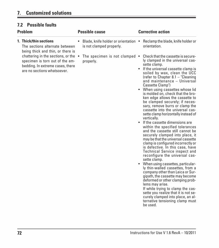
72 Instructions for Use V 1.6 RevA – 10/2011
Problem Corrective actionPossible cause
7.2 Possible faults
7. Customized solutions
1. Thick/thin sectionsThe sections alternate betweenbeing thick and thin, or there ischattering in the sections, or thespecimen is torn out of the em-bedding. In extreme cases, thereare no sections whatsoever.
• Reclamp the blade, knife holder ororientation.
• Blade, knife holder or orientationis not clamped properly.
• Check that the cassette is secure-ly clamped in the universal cas-sette clamp.
• If the universal cassette clamp issoiled by wax, clean the UCC(refer to Chapter 8.1 – "Cleaningand maintenance – UniversalCassette Clamp")
• When using cassettes whose lidis molded on, check that the bro-ken edge allows the cassette tobe clamped securely; if neces-sary, remove burrs or clamp thecassette into the universal cas-sette clamp horizontally instead ofvertically.
• If the cassette dimensions arewithin the specified tolerancesand the cassette still cannot besecurely clamped into place, itmay be that the universal cassetteclamp is configured incorrectly oris defective. In this case, haveTechnical Service inspect andreconfigure the universal cas-sette clamp.
• When using cassettes, particular-ly thin-walled cassettes, from acompany other than Leica or Sur-gipath, the cassette may becomedeformed or other clamping prob-lems may arise.If while trying to clamp the cas-sette you realize that it is not se-curely clamped into place, an al-ternative tensioning clamp mustbe used.
• The specimen is not clampedproperly.

73Leica RM2255
7. Customized solutions
• The blade is dull.
• The specimen is too warm.
• The sectioning speed is too fast.
• There is an accumulation of par-affin on the rear pressure plate ofthe knife holder.
3. "Stripes" in sectionsFor knife holder E
2. Section compressionThe sections are very com-pressed, show folds or aresqueezed together.
• Adjust the sectioning speed and/or section thickness when sec-tioning. Select a thinner section.
• Remove paraffin from this area ona regular basis.
• Use another area of the blade ora new blade.
• Cool the specimen before sec-tioning.
• Reduce the sectioning speed.
• Too great of a sectioning forcewas applied.
4. Noises during sectioningThe knife "sings" when sectioninghard specimens. The sectionsshow scratches or chatter marks.
• The sectioning speed is too fast.• The clearance angle is too wide.
• Insufficient clamping of specimenclamp and/or knife holder.
• Select a slower sectioning speed.• Methodically reduce the clear-
ance angle setting until you havefound the optimum angle.
• Check all screw and clamp con-nections on the specimen holdersystem and the knife holder. Ifnecessary, tighten the levers andscrews.
5. High blade consumption
• Laterally displace the knife hold-er or insert a new blade.
• Insert a new pressure plate or usea new knife holder.
• Methodically experiment withlarger clearance angle settingsuntil you have found the optimumangle.
• The blade is dull.
• The pressure plate is damaged orincorrectly adjusted.
• Clearance angle of the knife/blade too small.
Problem Corrective actionPossible cause

74 Instructions for Use V 1.6 RevA – 10/2011
8.1 Cleaning the instrument
Always remove the knife / blade before detaching the knife holder from the instrument.Always put the knives back into the knife case when not in use!Never place a knife anywhere with the cutting edge facing upwards and never try to catch afalling knife!When using cleaners, comply with the safety instructions of the manufacturer and the labor-safety regulations of your laboratory!When cleaning the outer surfaces, do not use xylene, scouring powders or solvents containingacetone or xylene. Xylene or acetone will damage the finished surfaces!Ensure that liquids do not enter the interior of the instrument during cleaning!
Before each cleaning carry out the following preparatory steps:
8. Cleaning and maintenance
• Raise the specimen clamp to the upper endposition and activate the handwheel lock.
• Switch the unit off and unplug it.• Remove the blade from the knife holder and
insert it in the receptacle at the bottom ofthe dispenser, or remove the knife from theknife holder and put it back in the knife case.
• Remove knife holder base and knife holderfor cleaning.
Never place blade or knife holderswith/without base close to the edge ofthe table to prevent them from fallingdown.
Instrument and outside surfaces
If necessary, the varnished outside surfaces of the control panels can becleaned with a mild commercial household cleaner or soap water and thenbe wiped with a moist cloth.To remove paraffin residue, xylene substitutes, paraffin oil, or paraffin re-movers such as "Para Gard" (Polysciences) can be used.The instrument must be completely dry before it can be used again.
Cleaning the knife
Always wipe the knife from the back of the knife to the cutting edge. NEVER wipe in the oppo-site direction - risk of injury!
Clean using an alcohol-based solution or acetone.
• Remove the specimen from the specimenclamp.
• Remove section waste with a dry brush.• Remove specimen clamp and clean sepa-
rately.

75Leica RM2255
Take the knife holder apart for cleaning. To do so,proceed as follows:• Fold the knife guard (9) and ejector (84) down-
ward.• Rotate the clamping lever (11) of the lateral dis-
placement forwards and pull it out sideways.• Push the knife holder base plate (86) with the
pressure plate (83) until it can be removed fromthe segment arch (87).
• Rotate the blade clamping lever (10) downwardand pull it out sideways.
• Remove pressure plate (83).• Clean all parts of the knife holder.
If several knife holders are cleaned at thesame time, the parts must NOT be mixedup! Failure to adhere to this may result insectioning problems!
For cleaning and removal of paraffin, donot use xylene or cleaning fluids contain-ing alcohol (e.g. glass cleaner).
• Lay the removed parts on an absorbent cloth intothe drying chamber (up to a max. of 65 °C) and letthe paraffin contamination run off.
There is a burn hazard when removing theparts from the drying chamber (65°C).Wearing safety gloves is recommended!
• Dry knife holder and reassemble.• After cleaning the moving parts, apply a thin
coat of drive part oil to them (refer also toChapter 8.2.3).
• When installing the pressure plate (83), ensurethat the upper edge is parallel to and level withthe rear edge of the knife holder base (86) (seealso Fig. 44, Page 53).
Knife holder E
Fig. 74
10
11
9
Fig. 75
86
83
83
86
87
11
10
8. Cleaning and maintenance
84

76 Instructions for Use V 1.6 RevA – 10/2011
Universal cassette clamp
• Detach cassette clamp (13) for a thorough cleaning, removing allparaffin residues.
• For cleaning, do not use xylene. Use xylene substitutes or paraffinremovers such as "Para Gard."
• The cassette clamp (13) can also be placed in an oven heated to amaximum of 65 °C, until the liquid wax escapes.
• Remove paraffin residues with a dry cloth.
• After such a cleaning procedure in an oven, always be sure to lubri-cate the spiral springs (91) of the tension lever (60) and move it backand forth several times.
8.2 Maintenance
Fig. 76
Switch the unit off and unplug it. Useonly the supplied replacement fuses.Both fuses must have the same rating(check the imprint!).
• Insert a small screwdriver into the cutout(25) and carefully pry out the insert.
• Remove the voltage selector housing (21) to-gether with the fuses (23).
• Remove the fuses. While doing so, leave thevoltage selector switch block (24) in thehousing.
• Replace defective fuses and reinstall thevoltage selector into the instrument.
• Check that the correct voltage value is dis-played in the viewing window (22).
22
25 24 2123
21
Fig. 77
8.2.1 Replacing fuses
8. Cleaning and maintenance
60
13
91
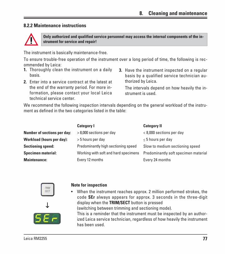
77Leica RM2255
8.2.2 Maintenance instructions
Only authorized and qualified service personnel may access the internal components of the in-strument for service and repair!
Note for inspection• When the instrument reaches approx. 2 million performed strokes, the
code SEr always appears for approx. 3 seconds in the three-digitdisplay when the TRIM/SECT button is pressed(switching between trimming and sectioning mode).This is a reminder that the instrument must be inspected by an author-ized Leica service technician, regardless of how heavily the instrumenthas been used.
↓↓↓↓↓
The instrument is basically maintenance-free.To ensure trouble-free operation of the instrument over a long period of time, the following is rec-ommended by Leica:
3. Have the instrument inspected on a regularbasis by a qualified service technician au-thorized by Leica.The intervals depend on how heavily the in-strument is used.
1. Thoroughly clean the instrument on a dailybasis.
2. Enter into a service contract at the latest atthe end of the warranty period. For more in-formation, please contact your local Leicatechnical service center.
We recommend the following inspection intervals depending on the general workload of the instru-ment as defined in the two categories listed in the table:
8. Cleaning and maintenance
Category I
> 8,000 sections per day
> 5 hours per day
Predominantly high sectioning speed
Working with soft and hard specimens
Every 12 months
Number of sections per day:
Workload (hours per day):
Sectioning speed:
Specimen material:
Maintenance:
Category II
< 8,000 sections per day
< 5 hours per day
Slow to medium sectioning speed
Predominantly soft specimen material
Every 24 months
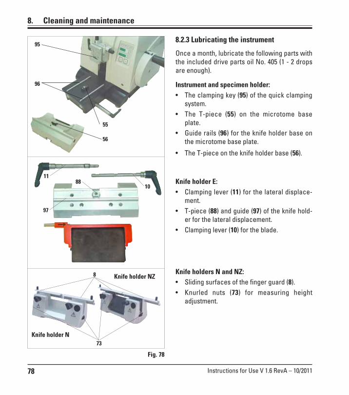
78 Instructions for Use V 1.6 RevA – 10/2011
97
88
• The T-piece on the knife holder base (56).
11
10Knife holder E:• Clamping lever (11) for the lateral displace-
ment.• T-piece (88) and guide (97) of the knife hold-
er for the lateral displacement.• Clamping lever (10) for the blade.
Fig. 78
Knife holders N and NZ:• Sliding surfaces of the finger guard (8).• Knurled nuts (73) for measuring height
adjustment.
95
96
55
8.2.3 Lubricating the instrument
Once a month, lubricate the following parts withthe included drive parts oil No. 405 (1 - 2 dropsare enough).
Instrument and specimen holder:• The clamping key (95) of the quick clamping
system.• The T-piece (55) on the microtome base
plate.• Guide rails (96) for the knife holder base on
the microtome base plate.56
8. Cleaning and maintenance
73
8
Knife holder N
Knife holder NZ
79Leica RM2255
9. Warranty and service
Warranty
Leica Biosystems Nussloch GmbH guarantees that the contractual prod-uct delivered has been subjected to a comprehensive quality control pro-cedure based on the Leica in-house testing standards, and that the prod-uct is faultless and complies with all technical specifications and/oragreed characteristics warranted.The scope of the warranty is based on the content of the concludedagreement. The warranty terms of your Leica sales organization or the or-ganization from which you have purchased the contractual product shallapply exclusively.
Service information
If you are in need of technical customer service or spare parts, pleasecontact your Leica representative or the Leica dealer where you pur-chased the instrument.Please provide the following information:
• Model name and serial number of the instrument.• Location of the instrument and name of the person to contact.• Reason for the service call.• Delivery date.
Decommissioning and disposal
The instrument or parts of the instrument must be disposed of accordingto existing local applicable regulations.Special attention should be paid to the lithium cell of the electronic circuitboard!

80 Instructions for Use V 1.6 RevA – 10/2011
Notes