rit senior design project 10662 d3 engineering camera platform friday november 6, 2009 9:00am to...
TRANSCRIPT

RIT Senior Design Project 10662D3 Engineering Camera Platform
Friday November 6, 2009 9:00am to 11:00am

Team Members• Gregory Hintz (EE)
– Project Manager • Samuel Skalicky (CE)
– Lead Engineer, FPGA Board• Jeremy Greene (EE)
– Connector Board• Jared Burdick (EE)
– Power• Michelle Bard (ME)
– Environmental • Tony Perrone (ME)
– Physical Design

Advisors
• Scott Reardon (D3 Engineering)• Kevin Kearney (D3 Engineering)• Dr. Robert Kremens (RIT-Imaging Science)• Philip Bryan (RIT – Industry Guide)

Project Status
• Risks
• BOM
• Analysis
• Feasibility
• Designs
• Test Plans

Schedule for the Design Review
• Overview – Gregory Hintz
• Electrical Discussion• Processor Board and FPGA
– Samuel Skalicky
• Connector Board, INS System– Jeremy Greene
• Mechanical Discussion• System Design
– Tony Perrone
• Environmental Concerns– Michelle Bard

What is the Customer Looking for?
•Integrate supplied components Ruggedized Unit Flight-capable packageCan record and transmit Capable of processing
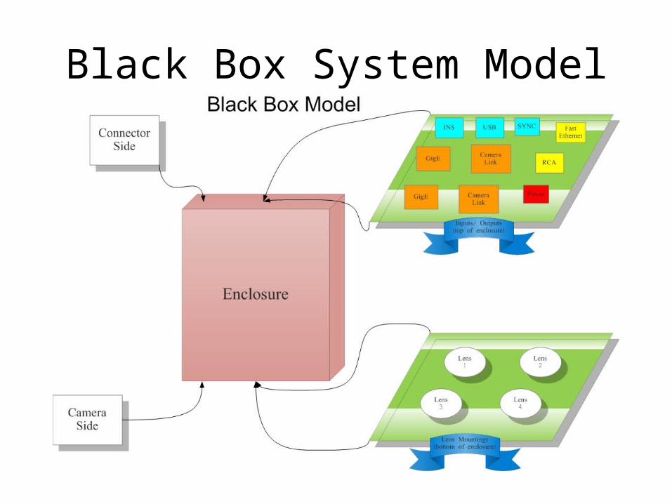
Black Box System Model

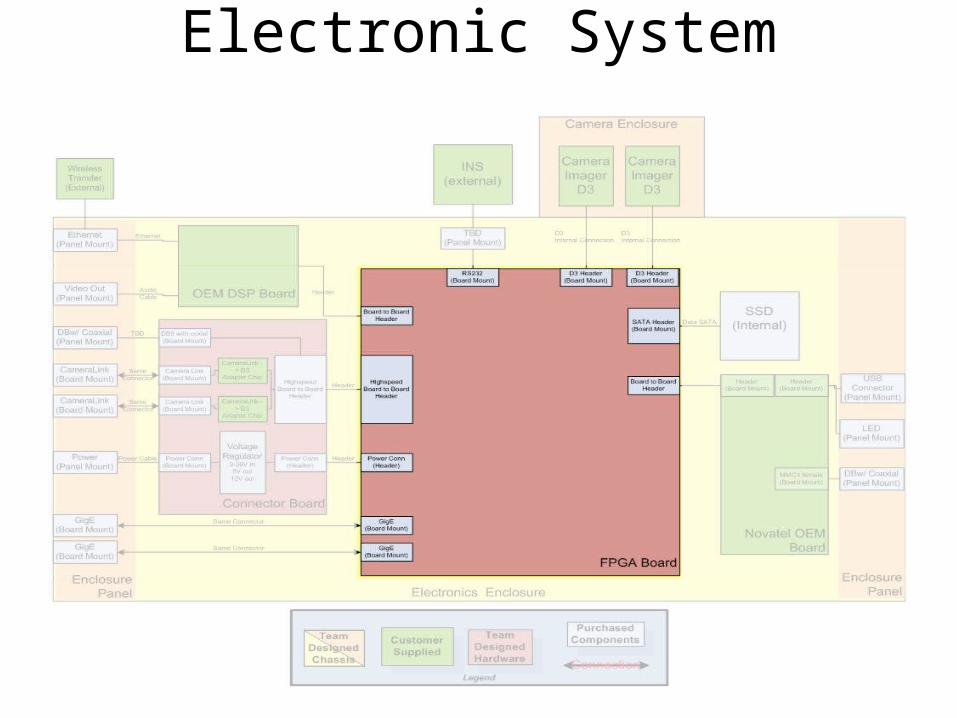
Electronic System

1. Integrate supplied componentsA. 10MP Visual Band CameraB. 1.3MP IR CameraC. Spatial Sensors
i. NovAtel OEM Board OEMV3ii. NovAtel OEM Board OEMV2
D. Camera Processing Board2. Capture data from two cameras3. Capture 10MP @ 1fps4. Capture 1.3MP @ 30fps5. Capture INS data @ 30/sec
(simultaneously)
Supplied Components
Customer Needs Met
6. External INS units7. Data processing (overlay)8. Real time viewing9. Store full-res. Data during flight10. Support NovAtel GNSS board

Electronic System

1. Integrate supplied componentsA. 10MP Visual Band CameraB. 1.3MP IR CameraC. Spatial Sensors
i. NovAtel OEM Board OEMV3ii. NovAtel OEM Board OEMV2
D. Camera Processing Board2. Capture data from two cameras3. Capture 10MP @ 1fps4. Capture 1.3MP @ 30fps5. Capture INS data @ 30/sec
(simultaneously)
Camera Components
Customer Needs Met
6. External INS units7. Data processing (overlay)8. Real time viewing9. Store full-res. Data during flight10. Support NovAtel GNSS board

Final Output 10mp Camera

Electronic System

1. Integrate supplied componentsA. 10MP Visual Band CameraB. 1.3MP IR CameraC. Spatial Sensors
i. NovAtel OEM Board OEMV3ii. NovAtel OEM Board OEMV2
D. Camera Processing Board2. Capture data from two cameras3. Capture 10MP @ 1fps4. Capture 1.3MP @ 30fps5. Capture INS data @ 30/sec
(simultaneously)
Camera Components
Customer Needs Met
6. External INS units7. Data processing (overlay)8. Real time viewing9. Store full-res. Data during flight10. Support NovAtel GNSS board

Final Output CameraLink® IR camera

Electronic System

1. Integrate supplied componentsA. 10MP Visual Band CameraB. 1.3MP IR CameraC. Spatial Sensors
i. NovAtel OEM Board OEMV3ii. NovAtel OEM Board OEMV2
D. Camera Processing Board2. Capture data from two cameras3. Capture 10MP @ 1fps4. Capture 1.3MP @ 30fps5. Capture INS data @ 30/sec
(simultaneously)
Spatial Sensing
Customer Needs Met
6. External INS units7. Data processing (overlay)8. Real time viewing9. Store full-res. Data during flight10. Support NovAtel GNSS board

Output INS data format
# of shot, (FLIGHT INFORMATION, Pitch, ect….)
675,495060.000000,39.377116,-82.774721,1442.237213,177.966706,-6.573488,87.156026676,495063.000000,39.375698,-82.773364,1437.212509,178.655193,-2.978762,89.591399677,495066.000000,39.374288,-82.771967,1432.054779,177.896426,-3.434334,92.544970678,495069.000000,39.372892,-82.770509,1428.557648,177.391126,-12.302477,92.517868679,495072.000000,39.371514,-82.768882,1425.166306,178.138512,-9.035039,88.154010680,495075.000000,39.370128,-82.767133,1425.035141,176.875920,-1.502685,89.783104681,495078.000000,39.368761,-82.765407,1424.326828,176.056416,-6.737449,90.066296682,495081.000000,39.367471,-82.763622,1421.768311,175.569431,-7.973052,88.809422683,495084.000000,39.366537,-82.761748,1427.402252,176.045872,-7.985133,86.404080

Electronic System

1. Integrate supplied componentsA. 10MP Visual Band CameraB. 1.3MP IR CameraC. Spatial Sensors
i. NovAtel OEM Board OEMV3ii. NovAtel OEM Board OEMV2
D. Camera Processing Board2. Capture data from two cameras3. Capture 10MP @ 1fps4. Capture 1.3MP @ 30fps5. Capture INS data @ 30/sec
(simultaneously)
Processing elements
Customer Needs Met
6. External INS units7. Data processing (overlay)8. Real time viewing9. Store full-res. Data during flight10. Support NovAtel GNSS board
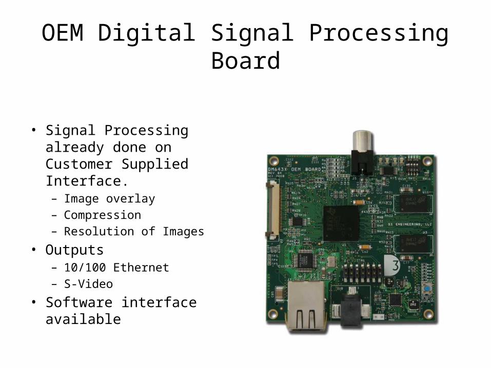
OEM Digital Signal Processing Board
• Signal Processing already done on Customer Supplied Interface. – Image overlay– Compression– Resolution of Images
• Outputs– 10/100 Ethernet– S-Video
• Software interface available

OEM Board
Electronic System

FPGA Board Diagram

FPGA Board to Scale

1. Integrate supplied componentsA. 10MP Visual Band CameraB. 1.3MP IR CameraC. Spatial SensorsD. Camera Processing Board
2. Capture data from two cameras3. Capture 10MP @ 1fps4. Capture 1.3MP @ 30fps5. Capture INS data @ 30/sec
(simultaneously)
Processing elements
Customer Needs Met
6. External INS units7. Data processing (overlay)8. Real time viewing9. Store full-res. Data during flight10. Support NovAtel GNSS board

FPGA• Inputs/Outputs• Flexible Architecture• Faster Speed• Parallel Processing
DSP• Energy Efficient• Single Pipeline• Easy Implementation• Math based ISA
Processing Elements

DSP
• Customer programmable– Encoding/Decoding media– Peripherals
• Role in this design– Image compression– Real time streaming of data– INS interface
• Required skills– Implementable Knowledge of C– DSP/BIOS

FPGA
• FPGA Selection– Quicker time to fabrication– Supreme configurability/Field reprogrammable– Has the I/O needed– Parallel processing

FPGA
• Xilinx Selection– Resources available to the team– Larger range of choices than other companies– Customer preference
• Model XC6SLX75T Selection– Package size (23mm x 23mm)– High speed transceiver count– I/O pin count– Cost effectiveness

FPGA Board Diagram

Data Flow – Initial Design• Pictures
Camera FPGA OEM
• INS Data
INS OEM

Data Flow – Final Design• Pictures
Camera FPGA OEM Camera FPGA HD
• INS Data
INS OEM FPGA HD

Data Speeds
**Note: baud = bits per second (RS-232)
• Image– IR: 30 images / second
• VGA=640x480• 9.2 MHz
– Visible :1 image / second• 10.7MP=3664x2748 • 10.07 MHz
• INS– 30 captures / second
• 1kB=8kb• 8000 baud

FPGA Pin Speeds
• Minimum values
– 13ns -> 76 MHz
– 5ns -> 200 MHz

System Software Design

FPGA Image Controller

Image Data Input

System Software Design

FPGA Central Dispatch

External Interfaces andthe Connector Board
Interfaces Specified Originally
2x Camera Link camera 2x Gigabit Ethernet camera
Power Supply (9V to 36V) 10/100 Ethernet
External Inertial Navigation System
Power Supply
External INS
2x GigE 2x Camera Link 10/100 Ethernet
Connector Board D3 OEM Board

External Interfaces andthe Connector Board
Final Interfaces Specified
2x Camera Link camera 2x GigE camera
Power Supply (9V to 36V) 10/100 Ethernet
External Inertial Navigation System RCA output
USB port
PowerSupply
2x Camera Link
External INS
RCA output
USB port
2x GigE
10/100 Ethernet
Connector Panel

External Interfaces andthe Connector Board
• Goal:– All interfaces routed through and mounted on the
Connector Board• Reality:– Various different mountings and routings
necessary

Interface Routing andConnector Mounting
Through the Connector Board Routed Elsewhere
Board Mount 2x Camera Link camera 2x GigE camera
Panel Mount
Power Supply (9V to 36V) 10/100 Ethernet
External INS RCA output
USB port
Power Supply2x Camera Link External INS
•2x Camera Link = nearly full width of Connector Board
Connector Panel

Interface Routing andConnector Mounting
Through the Connector Board Routed Elsewhere
Board Mount 2x Camera Link camera 2x GigE camera
Panel Mount
Power Supply (9V to 36V) 10/100 Ethernet
External INS RCA output
USB port
2x GigE
•GigE mounted on FPGA Board
FPGA Board (bottom view)Connector Panel

Interface Routing andConnector Mounting
Through the Connector Board Routed Elsewhere
Board Mount 2x Camera Link camera 2x GigE camera
Panel Mount
Power Supply (9V to 36V) 10/100 Ethernet
External INS RCA output
USB port
RCA output
10/100Ethernet
D3 OEM Board (top view)
•RCA and 10/100 Ethernet routed directly to D3 OEM Board
RCA
Connector Panel
10/100 Ethernet

Through the Connector Board Routed Elsewhere
Board Mount 2x Camera Link camera 2x GigE camera
Panel Mount
Power Supply (9V to 36V) 10/100 Ethernet
External INS RCA output
USB port
Interface Routing andConnector Mounting
USB port
Connector Panel
•USB routed directly to internal GNSS receiver

The Connector Board
• Having determined what it needs to do, design could commence
Customer Provided Block Diagram

Connector Board Design:Functional Block Diagram
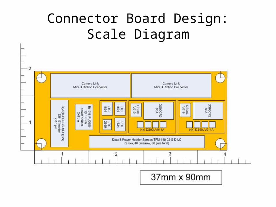
Connector Board Design:Scale Diagram
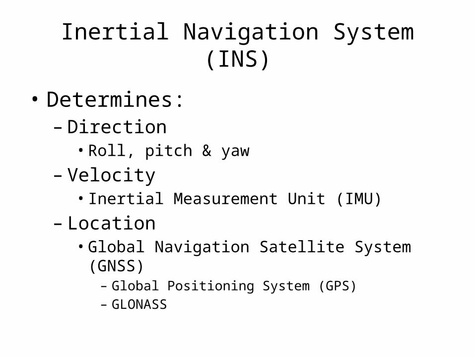
Inertial Navigation System (INS)
• Determines:– Direction• Roll, pitch & yaw
– Velocity • Inertial Measurement Unit (IMU)
– Location• Global Navigation Satellite System (GNSS)
– Global Positioning System (GPS)– GLONASS

Global Navigation Satellite System
• Customer Specified– NovAtel OEMV-2 or OEMV-3• RS-232 interface• Different power requirements
OEMV-2: 3.3 +5%/-3% VDC OEMV-3: 4.5 to 18 VDC

GNSS Software

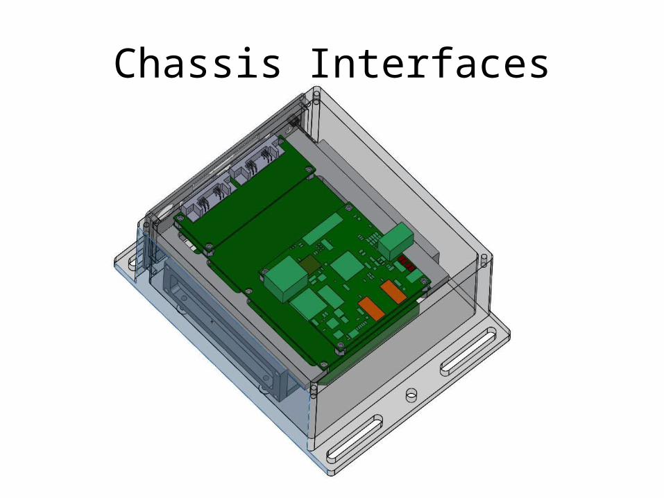
Chassis Interfaces
Interface to Plane
Small Passenger Aircraft RIT U.A.V. Airframe “C”Mountable to a flat plate Mountable to a flat wooden baseSmaller than a person; Approx 2’ x 2’ x 5’6” tall
Less than 16” x 6.5” x 5” tall
Less than 150lbs (68kg) Less than 15lbs (6.8kg)

Chassis Interfaces
Interface to Plane• 10.25” Long• 6” Wide• 6.5” Tall• 10.9lbs

Chassis Interfaces
Interface to Plane
Component Weight (lbs)
Electronics 0.91
Electronics Enclosure 3.43
Optics 2.15
Optics Enclosure 4.32
Total 11 lbs (Approximate)

Chassis Interfaces
D3 OEM BoardNovAtel OEMV-3FPGA BoardConnector BoardSolid State Hard Drive (Not Pictured)
Chassis Interfaces

Chassis InterfacesCamera BoardsLinos Mevis-C Lenses (16 mm)
MicroStrain IMU

Chassis Interfaces

Vibration Damping
Two sources of need:1. Insure structural integrity under vibration2. Minimize image distortion
Item 1 must be tested for, but item 2 can be calculated and designed for.
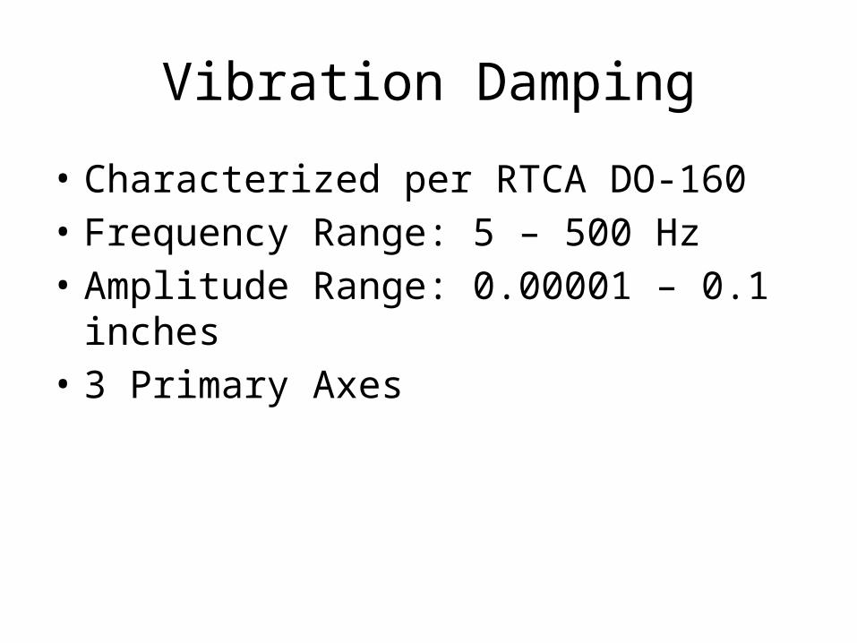
Vibration Damping
• Characterized per RTCA DO-160• Frequency Range: 5 – 500 Hz• Amplitude Range: 0.00001 – 0.1 inches• 3 Primary Axes
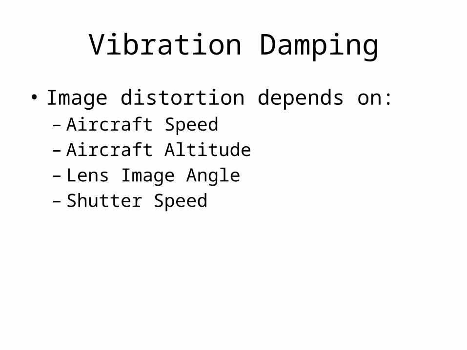
Vibration Damping
• Image distortion depends on:– Aircraft Speed– Aircraft Altitude– Lens Image Angle– Shutter Speed

Vibration Damping
• Speed induced byvibration taken as derivative of vibration motion profile
• Profile:X = A·sin(F·t)
• Speed:X’ = A·F·cos(F·t)
-1.5
-1
-0.5
0
0.5
1
1.5

Vibration Damping
• Maximum Aircraft Speed: 36 m/s• Maximum Vibration Speed: 1.27 m/s
Altitude (ft) Speed Distortion (Pixels)
Vibration Distortion (Pixels)
1000 0.66 0.02331500 0.44 0.01552000 0.33 0.01165000 0.13 0.0047

Environmental Needs
Maintain internal temp within operating temp of components
• Optics:• 10 Mp cameras
» -40 < 0 < 70
• Electronics (all temps in C)
• FPGA » 0 < T < 85
• Connector Board» 0 < T < 70
• D3 supplied OEM Board» -40 < T < 85
– Electronics Range • 0C < T < 70C

Environmental Needs • Allow for standard Environmental conditions as defined by MIL-STD-810G and DO-160
Temperature Range: -32C to 45 C (on ground)Humidity: 90%
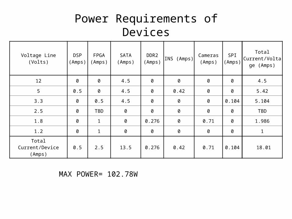
Power Requirements of Devices
Voltage Line (Volts) DSP (Amps)
FPGA (Amps) SATA (Amps) DDR2
(Amps) INS (Amps) Cameras (Amps)
SPI (Amps)
Total Current/Voltage
(Amps)
12 0 0 4.5 0 0 0 0 4.5
5 0.5 0 4.5 0 0.42 0 0 5.42
3.3 0 0.5 4.5 0 0 0 0.104 5.104
2.5 0 TBD 0 0 0 0 0 TBD
1.8 0 1 0 0.276 0 0.71 0 1.986
1.2 0 1 0 0 0 0 0 1
Total Current/Device (Amps) 0.5 2.5 13.5 0.276 0.42 0.71 0.104 18.01
MAX POWER= 102.78W

Environmental Management: Heat• Major sources of heat generation inside chassis
– Hard drive • about the half the heat produced comes from this
– Voltage Regulator– FPGA– DSP
• Net Heat generated by system can be estimated using the net power input to the system

Environmental Management:Heat Transfer analysis
Heat Transfer model: assuming a steady state • Radiation
– Least efficient mode– Model as black body
• From electronics to chassis• From chassis to external environment
– Model dependant primarily on surface area of components q rad
• T Chassis• TAmbient
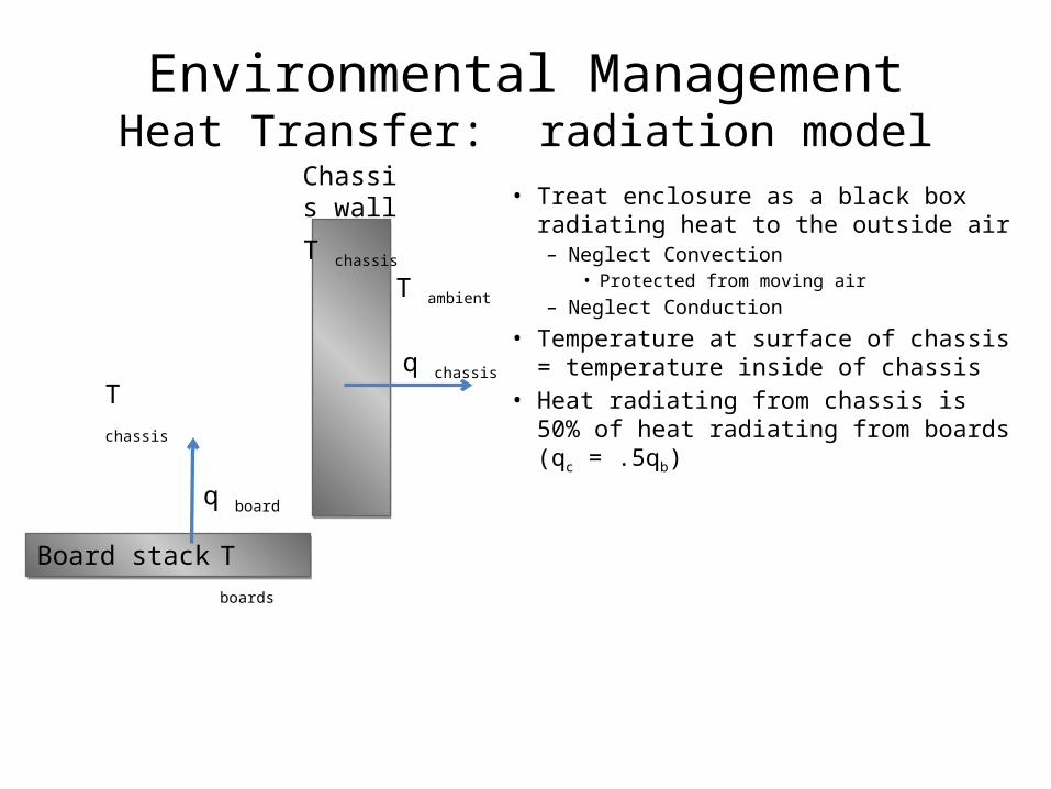
Environmental ManagementHeat Transfer: radiation model
• Treat enclosure as a black box radiating heat to the outside air– Neglect Convection
• Protected from moving air– Neglect Conduction
• Temperature at surface of chassis = temperature inside of chassis
• Heat radiating from chassis is 50% of heat radiating from boards (qc = .5qb)
Board stackBoard stack
Chassis wall
q chassis
q board
T chassis
T boards
T ambient
T chassis
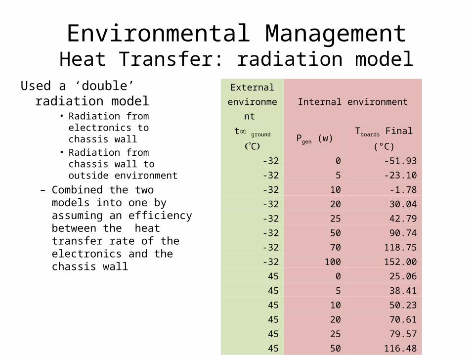
Environmental ManagementHeat Transfer: radiation model
Used a ‘double’ radiation model
• Radiation from electronics to chassis wall
• Radiation from chassis wall to outside environment
– Combined the two models into one by assuming an efficiency between the heat transfer rate of the electronics and the chassis wall
External environment Internal environment
t¥ ground (°C) Pgen (w) Tboards Final (°C)
-32 0 -51.93-32 5 -23.10-32 10 -1.78-32 20 30.04-32 25 42.79-32 50 90.74-32 70 118.75-32 100 152.0045 0 25.0645 5 38.4145 10 50.2345 20 70.6145 25 79.5745 50 116.4845 70 139.8845 100 168.90
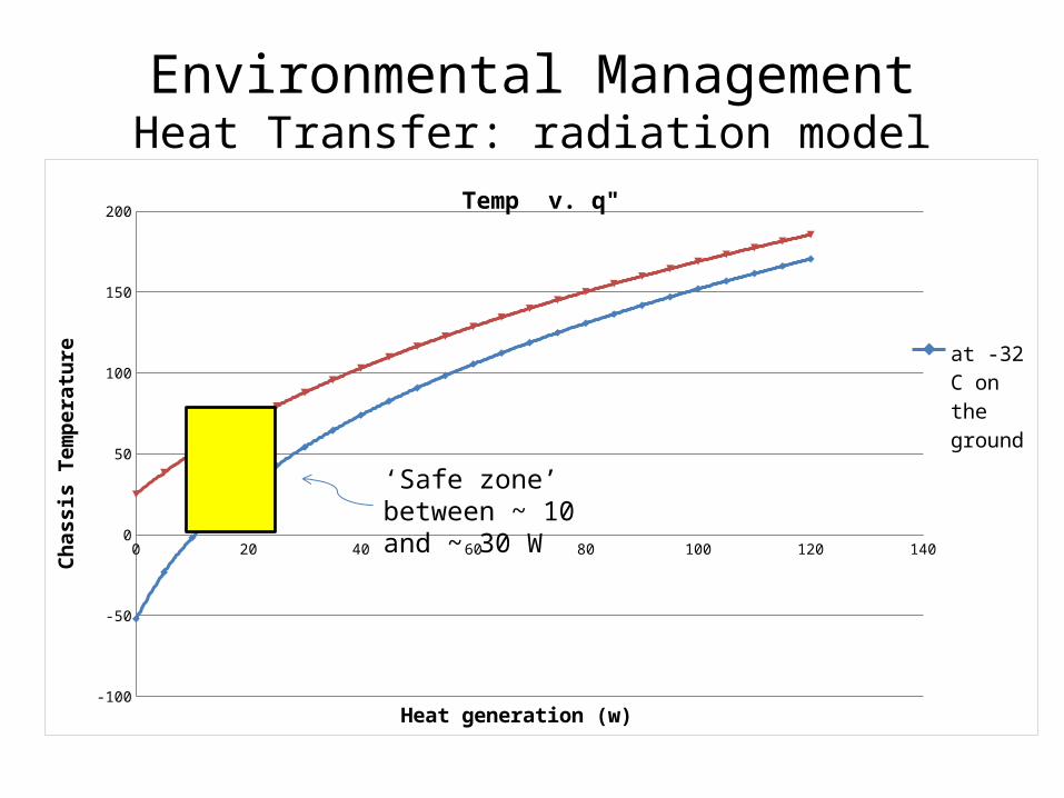
Environmental ManagementHeat Transfer: radiation model
0 20 40 60 80 100 120 140
-100
-50
0
50
100
150
200Temp v. q"
at -32 C on the ground
at 45 C on the ground
Heat generation (w)
Chas
sis
Tem
pera
ture
‘Safe zone’ between ~ 10 and ~ 30 W

Environmental Management : Humiditydew point: should we be concerned with condensation?
• Temperature at which water will condense on a surface– Function of ambient temperature
and relative humidity– Used to determine whether
additional steps should be taken to control temperature/ humidity inside the chassis.
• Conclusion: Condensation will not be a big problem – May run into trouble at very high
humidities (above 80%)• Dew point is very close to air
temperatures
environmental data dew point solution
relative humidity (%) t¥ air (°c) dew point ( C)
1 -51.7815 -83.236
40 -51.7815 -58.846
50 -51.7815 -57.167
80 -51.7815 -53.544
90 -51.7815 -52.617
1 25.21848 -34.858
40 25.21848 10.652
50 25.21848 14.052
80 25.21848 21.519
90 25.21848 23.459

Environmental Managementdew point: should we be concerned with condensation?
• Some environmental management techniques may be valuable to prevent condensation at high humidities– Main options:
• include a heating system to keep temperature inside the chassis above dew point• reduce humidity inside the chassis to lower the dew point inside the chassis
» a common method : silica gel packs
condensation control selection matrix
Heater system silica gel packweight rank with weight rank with weight
effective at reducing/preventing condensation 5 2 10 2 10simplicity in manufacturing/implimentation 3 -1 -3 1 3reusability 1 2 2 2 2allows for flexability as heat requirements change 4 1 4 2 8allows for air/water tight enclosure 2 2 4 4 8total: 17 27

RIT Senior Design Project 10662D3 Engineering Camera Platform
Friday November 6, 2009 9:00am to 11:00am
RIT Senior Design Project 10662D3 Engineering Camera Platform
Friday November 6, 2009 9:00am to 11:00am

RIT Senior Design Project 10662D3 Engineering Camera Platform
Friday November 6, 2009 9:00am to 11:00am