risk management report - onyx healthcaredemo.onyx-healthcare.com/product/112/certification/rm...
TRANSCRIPT

VITA Electronics Co., LTD.
Issue Date: 2015-11-10 Report No:RM1511051
1 of 41 Ver. 1.0
Risk Management Report
Organization’s Name ................ : VITA ELECTRONICS CO LTD
Address ..................................... : 5TH FL 101 CHOU TZE ST
NEIHU TAIPEI TAIWAN
Kind of Device ............................ Medical LCD Monitor
Model and/or Type Reference .. : MEDDP-515xxx-xx-xxxx, MEDDP-517xxx-xx-xxxx, MEDDP-519xxx-xx-xxxx (where x can be 0-9, A-Z for marketing purpose only, no technical difference)
Scope of the risk analysis ......... : 1. Intended use and identification of characteristics related to the safety of the medical equipment
2. Identification of hazards
3. Estimation of the risk for each hazardous situation
4. “Design, Development and Manufacture” of the product in question.
Prepared: Kevin Quality Assurance: Ken
Safety: Leo Sales: Kay
R&D: Kevin President: TK

VITA Electronics Co., LTD.
Issue Date: 2015-11-10 Report No:RM1511051
2 of 41 Ver. 1.0
Version Description Date
1.0 Initial 2015-11-10

VITA Electronics Co., LTD.
Issue Date: 2015-11-10 Report No:RM1511051
3 of 41 Ver. 1.0
Table of Content
1. Introduction ……………………………………………………………………..……4 2. Risk Management Policy ………………………………………………...… .…….4 3. Risk Management process…………………………………………………………4 4. Risk analysis ……………………………………………………………………..…105. Risk Evaluation…………………….………………………………………………..226. Risk Control …………………………………………………………………………267. Evaluation of overall residual risk acceptability …………………………………418. Risk management report ……………………………… …………………………41

VITA Electronics Co., LTD.
Issue Date: 2015-11-10 Report No:RM1511051
4 of 41 Ver. 1.0
1. Introduction
This report specifies a process to identify the hazards associated with medical devices to estimate and evaluate the associated risks, to control these risks, and to monitor the effectiveness of the controls. Bibliography:
Item Standard no. safety IEC60601-1: 2005+ A1: 2012
ANSI/AAMI ES60601-1 (2005/(R)2012 + A1:2012, C1:2009/(R)2012 + A2:2010/(R)2012) CAN/CSA-C22.2 No. 60601-1:14 EN60601-1:2006+A11:2011+A1:2013+A12:2014
EMC IEC 60601-1-2 Risk Management ISO14971: 2007
2. Risk Management Policy
Criteria for risk acceptability has defined based upon applicable national or regional regulations and relevant International Standards, and taken into account available information such as the generally accepted state of the art and known stakeholder concerns. Based on the guidelines being set up by the company management the identified risks will be evaluated in the risk management worksheet and reported in annual risk management reports as follows (according to ISO 14971): In determining acceptable risk, we will research pertinent regulations, standards and associated literature to identify state of the art for power supply with medical and dental equipment. The criteria of risk acceptability were according to requirement of IEC 60601-1.

VITA Electronics Co., LTD.
Issue Date: 2015-11-10 Report No:RM1511051
5 of 41 Ver. 1.0
3. Risk management process
3.1 Risk management process The risk management process will be conducted follow Standard ISO 14971 clause 3.1, in figure 1 as below.
Figure 1 – A schematic representation of the risk management process

VITA Electronics Co., LTD.
Issue Date: 2015-11-10 Report No:RM1511051
6 of 41 Ver. 1.0
3.2 Management responsibilities Top management / President opened the meeting for risk management process for following item - Assignment of qualified personnel - Adequate Resources - Policy for determining criteria for risk acceptability
See “meeting record of risk management” for details.
3.3 Qualification of personnel Persons performing risk management tasks shall have the knowledge and experience appropriate to the tasks assigned to them
Assigned Responsibility
Name Responsibilities in the whole Process Qualification
Record Ref. No.
Engineering Representative (R&D)
Kevin
- Responsible for carrying out the RM report (The person shall be trained ISO14971 or with relevant working experience.)
ISO14971 Training Record
Safety section Leo - Responsible for reviewing the RM report.
(The person shall be trained ISO14971 or with relevant working experience.)
ISO14971 Training Record
Sales department Kay - Responsible for collects data and from
customer and market ISO14971
Training RecordQuality Assurance (QA) Representative
Ken - Responsible for document any decisions
and actions taken. ISO14971
Training Record
President TK
- Responsibilities as below - Ensuring the provision of adequate resources - Ensuring the assignment of qualified personnel for risk management.
ISO14971 Training Record

VITA Electronics Co., LTD.
Issue Date: 2015-11-10 Report No:RM1511051
7 of 41 Ver. 1.0
3.4 Risk management plan Risk management activities was refer to Risk management plan (Document No “RP1511051”), include the following: a) The scope of the risk management plan is specified by the product LCD Monitor. And describing the medical device and the life-cycle phases for which each element of the plan is applicable. b) Assignment of responsibilities and authorities; See clause 3.3 for details. c) The review requirements of risk management activities was specified in Risk management plan (Document No “RP1511051”). d) The criteria for accepting risks shall considering the applicable national or regional requlations and relevant international standards, and take into account available information such as the generally accepted state of the art and known stakeholder concerns. The risk index matrix is disclosed in clause 3.4.1 e) The final verification of the risk control shall be performed on the prototype samples. The compliance reports according to IEC60601-1, IEC 60601-1-2 and qualification test report. f) Activities related to collection and review of relevant production and post-production information. See Attachment for Risk management plan for details.

VITA Electronics Co., LTD.
Issue Date: 2015-11-10 Report No:RM1511051
8 of 41 Ver. 1.0
3.4.1 Evaluation System Based on the guidelines being set up by the company management the identified risks will be evaluated
A: Probability of Occurrence (Improbable/Remote/Occasional/Probable/Frequent) Probability (Likelihood of event occurrence) Definition Common term Rank (1=lowest)
Frequent 5 With a probability of occurrence more than 10-3, or occurs more than once a month
Probable 4 With a probability of occurrence less than 10-3 but greater than 10-4, or occurs more than once a season
Occasional 3 With a probability of occurrence less than 10-4 but greater than 10-5, or occurs more than once a year
Remote 2 With a probability of occurrence less than 10-5 but greater than 10-6, or occurs more than once a product life-cycle
Improbable 1 With a probability of occurrence less than 10-6, unlikely to occur, but possible.
B: Severity of Harm (Negligible, Minor, Serious, Critical, Catastrophic) Severity (Impact of event occurrence) Definition Common term Rank (1=lowest)
Catastrophic 5 Could result in death, or life-threatening injury
Critical 4 Could result in permanent partial disability, injuries
Serious 3 Could result in injury requiring professional medical intervention
Minor 2 Could result in temporary injury not requiring professional medical intervention
Negligible 1 Inconvenience or temporary discomfort, these do not require any medical treatment.

VITA Electronics Co., LTD.
Issue Date: 2015-11-10 Report No:RM1511051
9 of 41 Ver. 1.0
The acceptance criteria are as following: Risk Index Matrix
Severity rank
Probability rank
1 2 3 4 5
4 Acceptable, Insignificant
risk
Unacceptable, moderate risk
Unacceptable, high risk
Unacceptable, high risk
Unacceptable, extreme risk
3 Acceptable, Insignificant
risk
Acceptable, Insignificant
risk
Unacceptable, moderate risk
Unacceptable, high risk
Unacceptable, high risk
2 Acceptable, Insignificant
risk
Acceptable, Insignificant
risk
Acceptable, Insignificant
risk
Unacceptable, moderate risk
Unacceptable, moderate risk
1 Acceptable, Insignificant
risk
Acceptable, Insignificant
risk
Acceptable, Insignificant
risk
Acceptable, Insignificant
risk
Unacceptable, moderate risk
Risk (index) acceptability level :
Risk= Severity x Probability
Result: Risk=1 to 4 is acceptable; Risk = 5 to 25 is unacceptable
The criteria was refer form risk Management Plan (Doc: RP1507063)
3.5 Risk management file Records of risk management activities, including any significant changes, are maintained
Description and reference to (ref number of) existing documents
Product tests according to 設計及開發程式 PN:QP0702
Process input (goods, resources, design etc.)
製程管制程序 P/N:QP0707
成品檢驗規定 P/N:QP0805
Post–production information and product surveillance on the markets
客訴流程管理辦法 P/N: QP0709
設計變更作業規定 P/N: QP0703
Product Problem record P/N: QP0710

VITA Electronics Co., LTD.
Issue Date: 2015-11-10 Report No:RM1511051
10 of 41 Ver. 1.0
4. Risk analysis 4.1 Risk analysis process Risk analysis performed as described according to ISO 14971, clause 4.2 to 4.4. The implementation of the planned risk analysis activities and the results of the risk analysis were recorded in the risk management file. 4.2 Intended use and identification of characteristics related to the safety of the
medical device (a) Questions: The following questions can aid the person in identifying all the characteristics of the medical
device that could affect safety. (Which according to ISO 14971)
Item Questions Answer / Comments
C.2.1 What is the intended use and how is the medical device to be used?
The LCD Monitor is intended to serve as a display-integrated computing platform for integration with hospital system. This device is designed for general purpose for hospital environment. For data collection and display for reference. It shall not be used for life-supporting system.
C.2.2 Is the medical device intended to be implanted? No, they are not intended to be implanted.
C.2.3 Is the medical device intended to be in contact with the patient or other person?
No applied part
C.2.4 What materials or components are utilized in the medical device or are used with, or are in contact with, the medical device?
The materials & components used are listed in BOM (bill of material).
C.2.5 Is energy delivered to or extracted from the patient?
No energy delivered to or extracted from the patient.
C.2.6 Are substances delivered to or extracted from the patient?
No delivered to or extracted from the patient.
C.2.7 Are biological materials processed by the medical device for sub-sequent re-use, transfusion or transplantation?
No biological materials process used.
C.2.8 Is the medical device supplied sterile or intended to be sterilized by the user, or are other microbiological controls applicable?
Not supplied sterile function or intended to be sterilized by the user.
C.2.9 Is the medical device intended to be routinely cleaned and disinfected by the user?
Not intended to be routinely cleaned and disinfected by the user.
C.2.10 Is the medical device intended to modify the patient environment?
No modify the patient environment function.
C.2.11 Are measurements taken? No measurement function.
C.2.12 Is the medical device interpretative? No data interpretative.
C.2.13 Is the medical device intended for use in conjunction with other medical devices, medicines or other medical technologies?
No, they are not.
C.2.14 Are there unwanted outputs of energy or substances?
Yes, they will bring about high temperature, leakage current and EMC.
C.2.15 Is the medical device susceptible to Yes, they may influence by temperature,

VITA Electronics Co., LTD.
Issue Date: 2015-11-10 Report No:RM1511051
11 of 41 Ver. 1.0
environmental influences? humidity, vibrations
C.2.16 Does the medical device influence the environment?
Yes, they may influence temperature and EMC
C.2.17 Are there essential consumables or accessories associated with the medical device?
No
C.2.18 Is maintenance or calibration necessary? No
C.2.19 Does the medical device contain software? No
C.2.20 Does the medical device have a restricted shelf life?
No
C.2.21 Are there any delayed or long-term use effects? No
C.2.22 What mechanical forces will the medical device be subjected to?
This LCD Monitor is subjected to such mechanical hazards as gravity (or instability), impact and drop.
C.2.23 What determines the lifetime of the medical device?
The service life is based on previous records and feedback of marketing in previous models.
C.2.24 Is the medical device intended for single use? This device not intended for single use.
C.2.25 Is safe decommissioning or disposal of the medical device necessary?
Yes, This device needs safe decommissioning or disposal.
C.2.26 Does installation or use of the medical device require special training or special skills?
It has to read the instruction manual before installation.
C.2.27 How will information for safe use be provided? Product specification or product data sheet Safety instructions will be provided according to IEC 60601-1:2005.
C.2.28 Will new manufacturing processes need to be established or introduced?
No
C.2.29 Is successful application of the medical device critically dependent on human factors such as the user interface?
No, it shall be evaluated in the final system.
C.2.29.1 Can the user interface design features contribute to use errors?
No
C.2.29.2 Is the medical device used in an environment where distractions can cause errors?
No
C.2.29.3 Does the medical device have connecting parts or accessories?
No
C.2.29.4 Does the medical device have a control interface?
No
C.2.29.5 Does the medical device display information? No
C.2.29.6 Is the medical device controlled by a menu? No
C.2.29.7 Will the medical device be used by persons with special needs?
No, it shall be evaluated in the final system.
C.2.29.8 Can the user interface be used to initiate user actions?
No
C.2.30 Does the medical device use an alarm system? No
C.2.31 In what way(s) might the medical device be No

VITA Electronics Co., LTD.
Issue Date: 2015-11-10 Report No:RM1511051
12 of 41 Ver. 1.0
deliberately misused?
C.2.32 Does the medical device hold data critical to patient care?
No
C.2.33 Is the medical device intended to be mobile or portable?
No, the device is a fixed installed equipment.
C.2.34 Does the use of the medical device depend on essential performance?
No, it shall be evaluated in the final system.
(b) Intended use and & most unfavorable maximum working load condition These Medical LCD Monitors are designed to use in displaying medical imaging data applications. These products cannot be used in patient vicinity. The LCD displays and the power supply must not be used outdoors or in areas where an explosion hazard may occur. They are intended to connect to specified power adaptor and equipped with VGA/HDMI/DP ports. The user has to make sure that requirements from IEC 60601-1 are fulfilled, especially in combination from monitor with other electrical equipment. It shall not be used for life supporting system.
The unit can only use with switching power adapter as following
Maximum operation temperature 40 degree C
The metal enclosure of LCD Monitor can be touched within 1 sec to 10 sec and plastic enclosure can be touched within 10 sec to 1 mins. Power adapter can be touched within 10 sec to 1 mins. Touch screen can be touched within 10 sec to 1 mins. Pollution degree of equipment: Pollution Degree 2 Operation altitude of equipment: 0-3000m
Power Adapter ADAPTER TECHNOLOGY CO LTD.
ATM065-P120 I/P: 100-240 Vac, 50/60 Hz, 1.6-0.7A O/P: 12 Vdc, 5A; 60W
Two MOPP insulation is provided between primary and secondary circuit in evaluated power adapter.

VITA Electronics Co., LTD.
Issue Date: 2015-11-10 Report No:RM1511051
13 of 41 Ver. 1.0
Model MEDDP-515xxx-xx-xxxx (DC)
LCD Panel Size: Pixel Pitch: Brightness: Contrast Ratio: Response Time:
15”
0.297mm 450 cd/㎡
800:1(typ.) 8mS(typ.)
Maximum viewable size 15 inch (38.1cm)
Video Input Analog:15-pin, D-sub connector Digital: DVI,DP,HDMI connector
Display area 304.128mmx 228.096mm (H×V)
Input voltage: Consumption
12V DC / 2A
12 watts maximum
External controls Power-switch, VGA, DVI,DP,HDMI Brightness, Contrast, Volume, Color temperature (User,6500°K,9300°K),
Clock, Phase, H-position, V-position, OSD-control, Recall, Sharpness, Exit
Horizontal frequency 30-60KHz
Vertical frequency 50-75Hz
Dimensions(with carton) 410mm×140mm×420mm (W×D×H)
Max. Resolution 1920×1080 (Non-Interlaced)
Power Saving With EPA standard
Plug & Play DDC 1/2B
Weight N.W.:3.2 Kgs G.W.:4.0 Kgs
Ambient temperature Operation: Non-operating
5°C – 40°C
-10°C – 60°C
Humidity Operating: Storage:
20%-80% 10%-90%
*Specifications are subject to change without notice.

VITA Electronics Co., LTD.
Issue Date: 2015-11-10 Report No:RM1511051
14 of 41 Ver. 1.0
Model MEDDP-517xxx-xxxxxxx (DC)
LCD Panel Size: Pixel Pitch: Brightness: Contrast Ratio: Response Time:
17”
0.264mm 350 cd/㎡
1000:1(typ.) 5mS(typ.)
Maximum viewable size 17 inch (43.2cm)
Video Input Analog:15-pin, D-sub connector Digital: DVI,DP,HDMI connector
Display area 337.920mmx 270.336mm (H×V)
Input voltage: Consumption
12V DC / 3A
15 watts maximum
External controls Power-switch, VGA, DVI,DP,HDMI Brightness, Contrast, Volume, Color temperature (User,6500°K,9300°K),
Clock, Phase, H-position, V-position, OSD-control, Recall, Sharpness, Exit
Horizontal frequency 30-60KHz
Vertical frequency 50-75Hz
Dimensions(with carton) 435mm×150mm×450mm (W×D×H)
Max. Resolution 1920×1080 (Non-Interlaced)
Power Saving With EPA standard
Plug & Play DDC 1/2B
Weight N.W.:4.0 Kgs G.W.:4.9 Kgs
Ambient temperature Operation: Non-operating
5°C – 40°C
-10°C – 60°C
Humidity Operating: Storage:
20%-80% 10%-90%
*Specifications are subject to change without notice.

VITA Electronics Co., LTD.
Issue Date: 2015-11-10 Report No:RM1511051
15 of 41 Ver. 1.0
Model MEDDP-519xxx-xxxxxxx (DC)
LCD Panel Size: Pixel Pitch: Brightness: Contrast Ratio: Response Time:
19”
0.294mm 350 cd/㎡
1000:1(typ.) 5mS(typ.)
Maximum viewable size 19 inch (48.26cm)
Video Input Analog:15-pin, D-sub connector Digital: DVI,DP,HDMI connector
Display area 376.32mmx 301.06mm (H×V)
Input voltage: Consumption
12V DC / 3A
19.7 watts maximum
External controls Power-switch, VGA, DVI,DP,HDMI Brightness, Contrast, Volume, Color temperature (User,6500°K,9300°K),
Clock, Phase, H-position, V-position, OSD-control, Recall, Sharpness, Exit
Horizontal frequency 30-60KHz
Vertical frequency 50-75Hz
Dimensions(with carton) 490mm×155mm×500mm (W×D×H)
Max. Resolution 1920×1080 (Non-Interlaced)
Power Saving With EPA standard
Plug & Play DDC 1/2B
Weight N.W.:4.9 Kgs G.W.:5.8 Kgs
Ambient temperature Operation: Non-operating
5°C – 40°C
-10°C – 60°C
Humidity Operating: Storage:
20%-80% 10%-90%
*Specifications are subject to change without notice.

VITA Electronics Co., LTD.
Issue Date: 2015-11-10 Report No:RM1511051
16 of 41 Ver. 1.0
The reasonably foreseeable misuse listed as below table.
Following list are on known and foreseeable hazards associated with the medical device in both normal and fault conditions.
Item Foreseeable misuse and hazards identification
A1 Output overload of power adapter
A2 Output short of power adapter
A3 Supply voltage mismatch
A4 Unit drop.
A5 Unit subjected to force.
A7 Premature unpacking, transport or storage
A8 Premature or excessive cleaning
4.3 Identification of hazards
Following list are identification of hazard for medical device, (Note: the evaluation of possible hazards by R/D engineer base on engineering judgment and ISO 14971)
Item hazards identification Hazards Type
B1 Line voltage from mains to cause hazard. Electromagnetic energy - Electric Shock
B2 Touch current (Enclosure leakage current) of accessible parts to cause hazard.
Electromagnetic energy - Leakage current
B3 Touch current (Output leakage current) of accessible parts to cause hazard.
Electromagnetic energy - Leakage current
B4 Stored energy to cause hazard. Electromagnetic energy - Electric Shock
B5 High temperature to cause hazard. Thermal energy – High temperature
B6 Input current of Label less than measured value of equipment may cause fire hazard.
Labelling - Inadequate description of
performance characteristics
B7 X capacitor connected between Line and Neutral may cause electric shock.
Electromagnetic energy - Electric Shock
B8 Fuse may not operate to cause fire hazard. Electromagnetic energy - Electric Shock
B9 Unsuitable rating of critical component to cause fire hazard.
Electromagnetic energy - Electric ShockThermal energy – High temperature
B10 Critical component fault to cause fire hazard Electromagnetic energy - Electric ShockThermal energy – High temperature
B11 High electrical voltage to cause insulating materials dielectric breakdown
Electromagnetic energy - Electric Shock
B12 Critical component or wires displaced to cause hazard
Mechanical energy - Vibration
B13 Physically equipment unstable in normal use to cause hazard
Mechanical energy - falling

VITA Electronics Co., LTD.
Issue Date: 2015-11-10 Report No:RM1511051
17 of 41 Ver. 1.0
Item hazards identification Hazards Type
B14 Overheat to cause thermoplastic materials shrinkage or distortion
Thermal energy – High temperature
B15 Openings of enclosure to cause fire hazard Thermal energy – High temperature
B16 Equipment expose at high humidity preconditioning treatment to cause electric shock.
Electromagnetic energy - Electric Shock
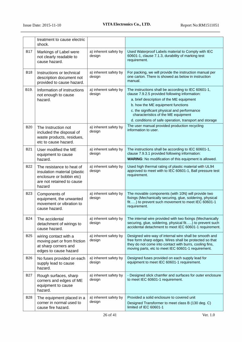
B17 Markings of Label were not clearly readable to cause hazard.
Labelling - Inadequate description of
performance characteristics
B18 Instructions or technical description document not provided to cause hazard.
Labelling - Inadequate description of
performance characteristics
B19. Information of instructions not enough to cause hazard.
Labelling - Inadequate description of
performance characteristics
B20 The Instruction not included the disposal of waste products, residues, etc to cause hazard.
Labelling - Inadequate description of
performance characteristics
B21 User modified the ME equipment to cause hazard. Labelling - Inadequate disclosure of
limitations
B22 The resistance to heat of insulation material (plastic enclosure or bobbin etc) are not retained to cause hazard
Thermal energy – High temperature
B23 Components of equipment, the unwanted movement or vibration to cause hazard.
Mechanical energy - Vibration
B24 The accidental detachment of wirings to cause hazard.
Mechanical energy - Vibration
B25 Wiring contact with a moving part or from friction at sharp corners and edges to cause hazard
Mechanical energy – sharp, edges
B26 No fuses provided on each supply lead to cause hazard.
Electromagnetic energy - Electric Shock
B27 Rough surfaces, sharp corners and edges of ME equipment to cause hazard.
Mechanical energy - Torsion, shear and tensile
B28 The equipment placed in a corner in normal used to cause fire hazard.
Thermal energy – High temperature
B29 Constructional of Fire Enclosure not meet IEC 60601-1, 3rd to cause hazard.
Thermal energy – High temperature
B30 Rating misused for Component Electromagnetic energy - Electric ShockThermal energy – High temperature
B31 Setting change of controls device Operational hazards - Function
B32 Indicator of power status Operational hazards – User error
B33 Arrangement of controls and indicators Operational hazards – User error
B34 SIO / SOP incorrect connected Operational hazards – User error

VITA Electronics Co., LTD.
Issue Date: 2015-11-10 Report No:RM1511051
18 of 41 Ver. 1.0
4.4 Estimation of the risks for each hazardous situation The decision of each hazardous risk were referred to recommendation of ISO14971, requirement of IEC 60601-1 and IEC 60601-1-2.
Item Initial Risk Estimation
Risk Probability Severity of the harm
Risk level (refer to chapter 3.3 Risk Index Matrix for
details)
Date of Assessment
A1 Output overload of power adapter 4 4 16 2015-11-10
A2 Output short of power adapter 4 3 12 2015-11-10
A3 Voltage mismatch. 4 4 16 2015-11-10
A4 Unit drop. 4 4 16 2015-11-10
A5 Unit subjected to force. 4 4 16 2015-11-10
A7 Premature unpacking, transport or storage 3 3 9 2015-11-10
A8 Premature or excessive cleaning 4 4 16 2015-11-10
B1 Line voltage from mains 3 5 15 2015-11-10
B2 Touch current (Enclosure leakage current) of accessible parts to cause hazard.
3 5 15 2015-11-10
B3 Touch current (Output leakage current) of accessible parts to cause hazard.
5 4 20 2015-11-10
B4 Stored energy 5 3 15 2015-11-10
B5 High temperature 5 2 10 2015-11-10
B6 Input current of Label less than measured value of equipment may cause fire hazard.
4 4 16 2015-11-10
B7 X capacitor connected between Line and Neutral may cause electric shock.
4 4 16 2015-11-10
B8 Fuse may not operate to cause fire hazard. 3 3 9 2015-11-10
B9 Unsuitable rating of critical component (transformer, main transistor, Bridge Rectifier, wiring….) to cause fire hazard.
5 4 20 2015-11-10
B10 Critical component fault (transformer, main transistor, Photo coupler, Bridge Rectifier…..) to cause fire hazard
5 4 20 2015-11-10
B11 High electrical voltage to cause insulating materials dielectric breakdown
5 4 20 2015-11-10
B12 Critical component or wires displaced to cause hazard
4 4 16 2015-11-10

VITA Electronics Co., LTD.
Issue Date: 2015-11-10 Report No:RM1511051
19 of 41 Ver. 1.0
Item Initial Risk Estimation
Risk Probability Severity of the harm
Risk level (refer to chapter 3.3 Risk Index Matrix for
details)
Date of Assessment
B13 Physically equipment unstable in normal use to cause hazard
3 3 9 2015-11-10
B14 Overheat to cause thermoplastic materials shrinkage or distortion
5 4 20 2015-11-10
B15 Openings of enclosure to cause fire hazard
5 3 15 2015-11-10
B16 Equipment expose at high humidity preconditioning treatment to cause electric shock.
4 4 16 2015-11-10
B17 Markings of Label were not clearly readable to cause hazard.
4 3 12 2015-11-10
B18 Instructions or technical description document not provided to cause hazard.
4 3 12 2015-11-10
B19 Information of instructions not enough to cause hazard.
3 3 9 2015-11-10
B20 The Instruction not included the disposal of waste products, residues, etc to cause hazard.
3 4 12 2015-11-10
B21 User modified the ME equipment to cause hazard.
3 3 9 2015-11-10
B22 The resistance to heat of insulation material (plastic enclosure or bobbin etc) are not retained to cause hazard
4 4 16 2015-11-10
B23 Components of equipment, the unwanted movement or vibration to cause hazard.
4 4 16 2015-11-10
B24 The accidental detachment of wirings to cause hazard.
3 3 9 2015-11-10
B25 wiring contact with a moving part or from friction at sharp corners and edges to cause hazard
4 3 12 2015-11-10
B26 No fuses provided on each supply lead to cause hazard.
4 3 12 2015-11-10
B27 Rough surfaces, sharp corners and edges of ME equipment to cause hazard.
4 3 12 2015-11-10
B28 The equipment placed in a corner in normal used to cause fire hazard.
4 3 12 2015-11-10

VITA Electronics Co., LTD.
Issue Date: 2015-11-10 Report No:RM1511051
20 of 41 Ver. 1.0
Item Initial Risk Estimation
Risk Probability Severity of the harm
Risk level (refer to chapter 3.3 Risk Index Matrix for
details)
Date of Assessment
B29 Constructional of Fire Enclosure not meet IEC 60601-1 to cause hazard.
4 3 15 2015-11-10
B30 Rating misused for Component
4 4 16 2015-11-10
B31 Setting change of controls device
5 1 5 2015-11-10
B32 Indicator of power status 3 4 12 2015-11-10
B33 Arrangement of controls and indicators
3 4 12 2015-11-10
B34 SIO / SOP incorrect connected
3 4 12 2015-11-10
Note:

VITA Electronics Co., LTD.
Issue Date: 2015-11-10 Report No:RM1511051
21 of 41 Ver. 1.0
5. Risk evaluation For each identified hazardous situation, the manufacturer shall decide, using the criteria defined in the risk management plan (Doc. No: P1006017), if risk reduction is required. If risk reduction is not required, the requirements given in 6.2 to 6.6 do not apply for this hazardous situation. The results of this risk evaluation were recorded as below.
Item Risk Risk level Risk=Severity x probability
Result: Risk=1~4, acceptable; 5~25, unacceptable
Date of Assessment
A1 Output overload. 16 (unacceptable, to be reduced) 2015-11-10
A2 Output short. 12 (unacceptable, to be reduced) 2015-11-10
A3 Voltage mismatch. 16 (unacceptable, to be reduced) 2015-11-10
A4 Unit drop. 16 (unacceptable, to be reduced) 2015-11-10
A5 Unit subjected to force. 16 (unacceptable, to be reduced) 2015-11-10
A6 Unit subjected to impact. 16 (unacceptable, to be reduced) 2015-11-10
A7 Premature unpacking, transport or storage
9 (unacceptable, to be reduced) 2015-11-10
A8 Premature or excessive cleaning
16 (unacceptable, to be reduced) 2015-11-10
B1 Line voltage from mains 15 (unacceptable, to be reduced) 2015-11-10
B2 Touch current (Enclosure leakage current) of accessible parts to cause hazard.
15 (unacceptable, to be reduced) 2015-11-10
B3 Touch current (Output leakage current) of accessible parts to cause hazard.
20 (unacceptable, to be reduced) 2015-11-10
B4 Stored energy 15 (unacceptable, to be reduced) 2015-11-10
B5 High temperature 10 (unacceptable, to be reduced) 2015-11-10
B6 Input current of Label less than measured value of equipment may cause fire hazard.
16 (unacceptable, to be reduced) 2015-11-10
B7 X capacitor connected between Line and Neutral may cause electric shock.
16 (unacceptable, to be reduced) 2015-11-10
B8 Fuse may not operate to cause fire hazard.
9 (unacceptable, to be reduced) 2015-11-10
B9 Unsuitable rating of critical component (transformer, main transistor, Bridge Rectifier, wiring….) to cause fire hazard.
20 (unacceptable, to be reduced) 2015-11-10
B10 Critical component fault (transformer, main transistor,
20 (unacceptable, to be reduced) 2015-11-10

VITA Electronics Co., LTD.
Issue Date: 2015-11-10 Report No:RM1511051
22 of 41 Ver. 1.0
Item Risk Risk level Risk=Severity x probability
Result: Risk=1~4, acceptable; 5~25, unacceptable
Date of Assessment
Photo coupler, Bridge Rectifier…..) to cause fire hazard
B11 High electrical voltage to cause insulating materials dielectric breakdown
20 (unacceptable, to be reduced) 2015-11-10
B12 Critical component or wires displaced to cause hazard
16 (unacceptable, to be reduced) 2015-11-10
B13 Physically equipment unstable in normal use to cause hazard
9 (unacceptable, to be reduced) 2015-11-10
B14 Overheat to cause thermoplastic materials shrinkage or distortion
20 (unacceptable, to be reduced) 2015-11-10
B15 Openings of enclosure to cause fire hazard
15 (unacceptable, to be reduced) 2015-11-10
B16 Equipment expose at high humidity preconditioning treatment to cause electric shock.
16 (unacceptable, to be reduced) 2015-11-10
B17 Markings of Label were not clearly readable to cause hazard.
12 (unacceptable, to be reduced) 2015-11-10
B18 Instructions or technical description document not provided to cause hazard.
12 (unacceptable, to be reduced) 2015-11-10
B19 Information of instructions not enough to cause hazard.
9 (unacceptable, to be reduced) 2015-11-10
B20 The Instruction not included the disposal of waste products, residues, etc to cause hazard.
12 (unacceptable, to be reduced) 2015-11-10
B21 User modified the ME equipment to cause hazard.
9 (unacceptable, to be reduced) 2015-11-10
B22 The resistance to heat of insulation material (plastic enclosure or bobbin etc) are not retained to cause hazard
16 (unacceptable, to be reduced) 2015-11-10
B23 Components of equipment, the unwanted movement or vibration to cause hazard.
16 (unacceptable, to be reduced) 2015-11-10
B24 The accidental detachment of wirings to cause hazard.
9 (unacceptable, to be reduced) 2015-11-10
B25 wiring contact with a moving part or from friction at sharp corners and edges to cause hazard
12 (unacceptable, to be reduced) 2015-11-10

VITA Electronics Co., LTD.
Issue Date: 2015-11-10 Report No:RM1511051
23 of 41 Ver. 1.0
Item Risk Risk level Risk=Severity x probability
Result: Risk=1~4, acceptable; 5~25, unacceptable
Date of Assessment
B26 No fuses provided on each supply lead to cause hazard.
12 (unacceptable, to be reduced) 2015-11-10
B27 Rough surfaces, sharp corners and edges of ME equipment to cause hazard.
12 (unacceptable, to be reduced) 2015-11-10
B28 The equipment placed in a corner in normal used to cause fire hazard.
12 (unacceptable, to be reduced) 2015-11-10
B29 Constructional of Fire Enclosure not meet IEC 60601-1 to cause hazard.
15 (unacceptable, to be reduced) 2015-11-10
B30 Rating misused for Component
16 (unacceptable, to be reduced) 2015-11-10
B31 Setting change of controls device
16 (unacceptable, to be reduced) 2015-11-10
B32 Indicator of power status 16 (unacceptable, to be reduced) 2015-11-10
B33 Arrangement of controls and indicators
16 (unacceptable, to be reduced) 2015-11-10
B34 SIO / SOP incorrect connected
16 (unacceptable, to be reduced) 2015-11-10

VITA Electronics Co., LTD.
Issue Date: 2015-11-10 Report No:RM1511051
24 of 41 Ver. 1.0
6. Risk control 6.1 Risk reduction Risk control activities was according to ISO 14971, clause 6.2 to 6.7 6.2 Risk control option analysis One of following risk control options apply: a) inherent safety by design; b) protective measures in the medical device itself or in the manufacturing process; c) information for safety
Item Risk Risk control option analysis
Note
A1 Output overload of power adapter
a) inherent safety by design
Used with IEC 60601-1 certificated power adapter.
The specified power adaptor were designed regulating network of OVP, OCP into circuit to Comply with IEC 60601-1, clause 13, single fault conditions test requirement.
A2 Output short of power adapter
a) inherent safety by design
Used with IEC 60601-1 certificated power adapter.
The specified power adaptor were designed regulating network of OVP, OCP into circuit to Comply with IEC 60601-1, clause 13, single fault conditions test requirement.
A3 Voltage mismatch. a) inherent safety by design
Used with IEC 60601-1 certificated power adapter.
The specified power adaptor were designed auto range (100-240Vac) for input circuit to Comply with IEC 60601-1, clause 13, single fault conditions test requirement.
And provided with polarized DC jack.
A4 Unit drop. a) inherent safety by design
Provided a solid and hard enclosure to covered unit to Comply with IEC 60601-1, clause 15.3, drop impact test requirement.
A5 Unit subjected to force. a) inherent safety by design
Provided a solid and hard enclosure to covered unit to Comply with IEC 60601-1, clause 15.3, enclosure mechanical strength test requirement.
A6 Unit subjected to impact. a) inherent safety by design
Provided a solid and hard enclosure to covered unit to Comply with IEC 60601-1, clause 15.3, drop impact test requirement.
A7 Premature unpacking, transport or storage
a) inherent safety by design
The outside of packaging marked environmental conditions for transport and storage according to IEC 60601-1, ISO 780 and ISO15223..
A8 Premature or excessive cleaning
a) inherent safety by design
Provided method of cleaning into user manual according to IEC 60601-1
B1 Line voltage from mains a) inherent safety by design
Used with IEC 60601-1 certificated power adapter.
The specified power adaptor were provided a solid enclosure to covered unit. And provided Double/Reinforced insulation and two MOPP between primary and secondary according to IEC 60601-1.

VITA Electronics Co., LTD.
Issue Date: 2015-11-10 Report No:RM1511051
25 of 41 Ver. 1.0
B2 Touch current (Enclosure leakage current) of accessible parts to cause hazard.
a) inherent safety by design
Used with IEC 60601-1 certificated power adapter.
The touch current for the output of adapter were met require of IEC 60601-1.
B3 Touch current (Output leakage current) of accessible parts to cause hazard
a) inherent safety by design
Used with IEC 60601-1 certificated power adapter.
The touch current for the outer enclosure of adapter were met require of IEC 60601-1.
B4 Stored energy a) inherent safety by design
Used with IEC 60601-1 certificated power adapter.
The discharge of AC inlet pins were met require of IEC 60601-1
B5 High temperature a) inherent safety by design
Used with IEC 60601-1 certificated power adapter.
And designed used with Low Power CPU.
B6 Input current of Label less than measured value of equipment may cause fire hazard.
a) inherent safety by design
Provided rating information on label drawing of unit to Comply with IEC 60601-1, clause 4.11, power input test requirement.
B7 X capacitor connected between Line and Neutral may cause electric shock.
a) inherent safety by design
Provided rating information on label drawing of unit to Comply with IEC 60601-1, clause 8.4.3, voltage limitation test requirement.
B8 Fuse may not operate to cause fire hazard.
a) inherent safety by design
Used with IEC 60601-1 certificated power adapter.
The specified power adaptor provided with main fuse, the fuse with IEC60127 standard approved to Comply with IEC 60601-1, clause 13, single fault conditions test requirement.
B9 Unsuitable rating of critical component to cause fire hazard.
a) inherent safety by design
According to our QMS procedure, all component are used within their specified ratings.
B10 Critical component fault to cause fire hazard
a) inherent safety by design
According to our QMS procedure, all components and wiring are used within their specified ratings.
and AC power Adapter Comply with IEC 60601-1, clause 13, single fault conditions test requirement.
B11 High electrical voltage to cause insulating materials dielectric breakdown
a) inherent safety by design
Insulation materials were used withstand voltage complies with standard requirement. And application was complying with IEC 60601-1 requirements.
B12 Critical component or wires displaced to cause hazard
a) inherent safety by design
The equipment designed provided two fixings (Mechanically securing, glue, soldering, physical fit…..) to prevent such movement. According to IEC 60601-1 requirement.
B13 Physically of equipment unstable in normal use to cause hazard
a) inherent safety by design
Designed steady and solid enclosure to covered unit. According to IEC 60601-1 requirement.
B14 Overheat to cause thermoplastic materials shrinkage or distortion
a) inherent safety by design
Used high thermal rating of thermoplastic enclosure with UL94 approved to meet with to IEC 60601-12 requirement.
B15 Openings of enclosure to cause fire hazard
a) inherent safety by design
Provided a solid and hard enclosure without openings to covered unit to Comply with IEC 60601-1 requirement.
B16 Equipment expose at high humidity preconditioning
a) inherent safety by design
Provided a solid, hard and tight enclosure to covered unit to Comply with IEC 60601-1, clause 5.7 requirement.
VITA Electronics Co., LTD.
Issue Date: 2015-11-10 Report No:RM1511051
26 of 41 Ver. 1.0
treatment to cause electric shock.
B17 Markings of Label were not clearly readable to cause hazard.
a) inherent safety by design
Used Waterproof Labels material to Comply with IEC 60601-1, clause 7.1.3, durability of marking test requirement.
B18 Instructions or technical description document not provided to cause hazard.
a) inherent safety by design
For packing, we will provide the instruction manual per one carton. There is showed as below in instruction manual.
B19. Information of instructions not enough to cause hazard.
a) inherent safety by design
The instructions shall be according to IEC 60601-1, clause 7.9.2.5 provided following information:
a. brief description of the ME equipment
b. how the ME equipment functions
c. the significant physical and performance characteristics of the ME equipment
d. conditions of safe operation, transport and storage
B20 The Instruction not included the disposal of waste products, residues, etc to cause hazard.
a) inherent safety by design
The user manual provided production recycling information to user.
B21 User modified the ME equipment to cause hazard.
a) inherent safety by design
The instructions shall be according to IEC 60601-1, clause 7.9.3.1 provided following information:
WARING: No modification of this equipment is allowed.
B22 The resistance to heat of insulation material (plastic enclosure or bobbin etc) are not retained to cause hazard
a) inherent safety by design
Used high thermal rating of plastic material with UL94 approved to meet with to IEC 60601-1, Ball pressure test requirement.
B23 Components of equipment, the unwanted movement or vibration to cause hazard.
a) inherent safety by design
The movable components (with 10N) will provide two fixings (Mechanically securing, glue, soldering, physical fit…..) to prevent such movement to meet IEC 60601-1 requirement.
B24 The accidental detachment of wirings to cause hazard.
a) inherent safety by design
The internal wire provided with two fixings (Mechanically securing, glue, soldering, physical fit…..) to prevent such accidental detachment to meet IEC 60601-1 requirement.
B25 wiring contact with a moving part or from friction at sharp corners and edges to cause hazard
a) inherent safety by design
Designed wire-way of internal wire shall be smooth and free form sharp edges. Wires shall be protected so that they do not come into contact with burrs, cooling fins, moving parts, etc to meet IEC 60601-1 requirement.
B26 No fuses provided on each supply lead to cause hazard.
a) inherent safety by design
Designed fuses provided on each supply lead for equipment to meet IEC 60601-1 requirement.
B27 Rough surfaces, sharp corners and edges of ME equipment to cause hazard.
a) inherent safety by design
- Designed slick chamfer and surfaces for outer enclosure to meet IEC 60601-1 requirement.
B28 The equipment placed in a corner in normal used to cause fire hazard.
a) inherent safety by design
Provided a solid enclosure to covered unit
Designed Transformer to meet class B (130 deg. C) limited of IEC 60601-1

VITA Electronics Co., LTD.
Issue Date: 2015-11-10 Report No:RM1511051
27 of 41 Ver. 1.0
B29 Constructional of Fire Enclosure not meet IEC 60601-1 to cause hazard.
a) inherent safety by design
Used flammability V-1 material for enclosure and designed on openings to meet IEC 60601-1, clause 11.3 requirement.
B30 Rating misused for Component
a) inherent safety by design
According to our QMS procedure, all components and wiring are used within their specified ratings and comply with components standard.
B31 Setting change of controls device
a) inherent safety by design
LED indicator used for controls status.
B32 Indicator of power status a) inherent safety by design
Provided a LED indicator for status of normal
B33 Arrangement of controls and indicators
a) inherent safety by design
Designed location of controls and indicators were easy and obvious to access by user.
B34 SIO / SOP incorrect connected
a) inherent safety by design
Provided a polarized connector and install information in user manual.

VITA Electronics Co., LTD.
Issue Date: 2015-11-10 Report No:RM1511051
28 of 41 Ver. 1.0
6.3 Implementation of risk control measure(s) All risk control measures were verified and effective. See below for details.
Item Risk verified Note
A1 Output overload. Provided with OVP, OCP circuit. Comply with IEC 60601-1, clause 13, single fault conditions test requirement.
A2 Output short. Provided with OVP, OCP circuit. Comply with IEC 60601-1, clause 13, single fault conditions test requirement.
A3 Voltage mismatch. Designed auto range (100-240Vac) for input circuit to
Comply with IEC 60601-1, clause 13, single fault conditions test requirement.
A4 Unit drop. Provided a solid and hard enclosure to covered unit
Comply with IEC 60601-1, clause 15.3, drop impact test requirement.
A5 Unit subjected to force.
Provided a solid and hard enclosure to covered unit to
Comply with IEC 60601-1, clause 15.3, enclosure mechanical strength test requirement.
A6 Unit subjected to impact.
Provided a solid and hard enclosure to covered unit to
Comply with IEC 60601-1, clause 15.3, drop impact test requirement.
A7 Premature unpacking, transport or storage
The outside of packaging marked environmental conditions for transport and storage
Comply with IEC 60601-1, clause 7.2.17 requirement.
A8 Premature or excessive cleaning
Provided method of cleaning into user manual
Comply with IEC 60601-1, clause 7.9.2.12 requirement.
B1 Line voltage from mains
Provided a solid enclosure to covered unit
Comply with IEC 60601-1, Double/Reinforced insulation requirement.
B2 Touch current (Enclosure leakage current) of accessible parts to cause hazard.
Changed rating of Y cap. and Bridge Cap.
Comply with IEC 60601-1, clause 8.7, leakage current test requirement.
B3 Touch current (Output leakage current) of accessible parts to cause hazard
Changed rating of Y cap. and Bridge Cap.
Comply with IEC 60601-1, clause 8.7, leakage current test requirement.
B4 Stored energy Changed rating of X cap. and Bleeder resistor
Comply with IEC 60601-1, clause 8.4.3 requirement.
B5 High temperature Provided a solid enclosure to covered unit
Comply with IEC 60601-1, Table 22, Table 23 requirement.
B6 Input current of Label less than measured value of equipment may cause fire hazard.
Provided rating information on label drawing of unit
Comply with IEC 60601-1, clause 4.11, power input test requirement.
B7 X capacitor connected between Line and
Provided rating information on label drawing of unit
Comply with IEC 60601-1, clause 8.4.3, voltage limitation test requirement.

VITA Electronics Co., LTD.
Issue Date: 2015-11-10 Report No:RM1511051
29 of 41 Ver. 1.0
Item Risk verified Note
Neutral may cause electric shock.
B8 Fuse may not operate to cause fire hazard.
Used fuse, the fuse with IEC60127 standard approved to
Comply with IEC 60601-1, clause 13, single fault conditions test requirement.
B9 Unsuitable rating of critical component (transformer, main transistor, Bridge Rectifier, wiring….) to cause fire hazard.
According to our QMS procedure to use within their specified ratings.
Comply with IEC 60601-1, clause 4.8 requirement.
B10 Critical component fault (transformer, main transistor, Photo coupler, Bridge Rectifier…..) to cause fire hazard
According to our QMS procedure, all components and wiring are used within their specified ratings.
Comply with IEC 60601-1, clause 13, single fault conditions test requirement.
B11 High electrical voltage to cause insulating materials dielectric breakdown
Insulation materials were used withstand voltage complies with standard requirement.
Complying with IEC 60601-1 clause 8.8 requirements.
B12 Critical component or wires displaced to cause hazard
The equipment designed provided two fixings (Mechanically securing, glue, soldering, physical fit…..) to prevent such movement.
Complying with IEC 60601-1 clause 9.3 requirements.
B13 Physically of equipment unstable in normal use to cause hazard
Designed steady and solid enclosure to covered unit.
Complying with IEC 60601-1 clause 9.4.3 requirements.
B14 Overheat to cause thermoplastic materials shrinkage or distortion
Used high thermal rating of thermoplastic enclosure with UL94 approved
Complying with IEC 60601-1 clause 4.8 requirements.
B15 Openings of enclosure to cause fire hazard
Provided a solid and hard enclosure without openings to covered unit to
Complying with IEC 60601-1 clause 11.3 requirements.
B16 Equipment expose at high humidity preconditioning treatment to cause electric shock.
Provided a solid, hard and tight enclosure to covered unit to Comply with IEC 60601-1, clause 5.7 requirement.
Complying with IEC 60601-1 clause 5.7 requirements.
B17 Markings of Label were not clearly readable to cause hazard.
Used Waterproof Labels material Comply with IEC 60601-1, clause 7.1.3, durability of marking test requirement.
B18 Instructions or technical description document not provided to cause
Provided with instruction manual Comply with IEC 60601-1, clause 7 requirement.

VITA Electronics Co., LTD.
Issue Date: 2015-11-10 Report No:RM1511051
30 of 41 Ver. 1.0
Item Risk verified Note
hazard.
B19.
Information of instructions not enough to cause hazard.
The instructions provided following information:
a. brief description of the ME equipment
b. how the ME equipment functions
c. the significant physical and performance characteristics of the ME equipment
d. conditions of safe operation, transport and storage
Comply with IEC 60601-1, clause 7 requirement.
B20 The Instruction not included the disposal of waste products, residues, etc to cause hazard.
The instructions provided following information:
- It was showed in the instruction manual, as “Do not dispose this product in the household waste, please, follow the respective national law for proper disposal.”
Comply with IEC 60601-1, clause 7 requirement.
B21 User modified the ME equipment to cause hazard.
The instructions provided following information:
WARING: Do not modify this equipment without authorization of the manufacturer.
Comply with IEC 60601-1, clause 7.9.3.1 requirement.
B22 The resistance to heat of insulation material (plastic enclosure or bobbin etc) are not retained to cause hazard
Used high thermal rating of plastic material with UL94 approved to meet with to IEC 60601-1, Ball pressure test requirement.
Comply with IEC 60601-1, clause 7.9.3.1 durability of marking test requirement.
B23 Components of equipment, the unwanted movement or vibration to cause hazard.
The movable components (with 10N) will provide two fixings (Mechanically securing, glue, soldering, physical fit…..) to prevent such movement to meet IEC 60601-1 requirement.
Comply with IEC 60601-1, clause 8.8.4.1 Ball pressure test requirement.
B24 The accidental detachment of wirings to cause hazard.
The internal wire provided with two fixings (Mechanically securing, glue, soldering, physical fit…..) to prevent such accidental detachment
Comply with IEC 60601-1, clause 8.10.1 requirement.
B25 wiring contact with a moving part or from friction at sharp corners and edges to cause hazard
Designed wire ways of internal wire shall be smooth and free form sharp edges. Wires shall be protected so that they do not come into contact with burrs, cooling fins, moving parts
Comply with IEC 60601-1, clause 8.10.1 requirement.
B26 No fuses provided on each supply lead to cause hazard.
Designed fuses provided on each supply lead.
Comply with IEC 60601-1, clause 8.11.5 requirement.
B27 Rough surfaces, sharp corners and
- Designed slick chamfer and surfaces for outer enclosure requirement.
Comply with IEC 60601-1, clause 9.3 requirement.

VITA Electronics Co., LTD.
Issue Date: 2015-11-10 Report No:RM1511051
31 of 41 Ver. 1.0
Item Risk verified Note
edges of ME equipment to cause hazard.
B28 The equipment placed in a corner in normal used to cause fire hazard.
Provided a solid enclosure to covered unit
Complying with IEC 60601-1 Table 22 requirements.
B29 Constructional of Fire Enclosure not meet IEC 60601-1 to cause hazard.
Used flammability V-1 material for enclosure
Complying with IEC 60601-1 clause 11.3 requirements.
B30 Rating misused for Component
According to our QMS procedure to use within their specified ratings.
Comply with IEC 60601-1, clause 4.8 requirement.
B31 Setting change of controls device
LED indicator used for controls status.
Comply with IEC 60601-1, clause 7.4.2 requirement.
B39 Indicator of power status
Provided a LED indicator for status
Comply with IEC 60601-1, clause 15.4.3.5 requirement.
B33 Arrangement of controls and indicators
Designed location of controls and indicators were easy and obvious to access by user.
Comply with IEC 60601-1, clause 15.1 requirement.
B34 SIO / SOP incorrect connected
Provided a polarized connector and install information in user manual.
Comply with IEC 60601-1, clause 15.4.1 requirement.

VITA Electronics Co., LTD.
Issue Date: 2015-11-10 Report No:RM1511051
32 of 41 Ver. 1.0
6.4 Residual risk evaluation According to procedure, all residual risks are judged acceptable. No further risk control measures shall be applied after the risk control measures are applied, See below table for details. Initial Risk Estimation
(Before Risk Control0
Risk control
measure
Risk Estimation (After Risk Control )
item Risk Probability Severity of the
harm
Risk level (refer to
chapter 3.3 Risk Index Matrix for details)
Probability Severity of the harm
Risk level (refer to
chapter 3.3 Risk Index Matrix for details)
A1 Output overload. 4 4 16 (unacceptable)
After risk control measure1)
2 2 4 (acceptable)
A2 Output short. 4 3 12 (unacceptable)
After risk control
measure1
2 2 4 (acceptable)
A3 Voltage mismatch. 4 4 16 (unacceptable)
After risk control
measure1
1 1 1 (acceptable)
A4 Unit drop. 4 4 16 (unacceptable)
After risk control
measure1
4 1 4 (acceptable)
A5 Unit subjected to force.
4 4 16 (unacceptable)
After risk control
measure1
4 1 4 (acceptable)
A6 Unit subjected to impact.
4 4 16 (unacceptable)
After risk control
measure1
4 1 4 (acceptable)
A7 Premature unpacking, transport or storage
3 3 9 (unacceptable)
After risk control
measure1
1 3 3 (acceptable)
A8 Premature or excessive cleaning
4 4 16 (unacceptable)
After risk control
measure1
2 1 2 (acceptable)
B1 Line voltage from mains
3 5 15 (unacceptable)
After risk control
measure1
1 2 2 (acceptable)
B2 Touch current (Enclosure leakage current) of accessible parts to cause hazard.
3 5 15 (unacceptable)
After risk control
measure1
1 2 2 (acceptable)
B3 Touch current (Output leakage current) of accessible parts to cause hazard
5 4 20 (unacceptable)
After risk control
measure1
1 2 2 (acceptable)
B4 Stored energy 5 3 15 (unacceptable)
After risk control
2 2 4

VITA Electronics Co., LTD.
Issue Date: 2015-11-10 Report No:RM1511051
33 of 41 Ver. 1.0
Initial Risk Estimation (Before Risk Control0
Risk control
measure
Risk Estimation (After Risk Control )
item Risk Probability Severity of the
harm
Risk level (refer to
chapter 3.3 Risk Index Matrix for details)
Probability Severity of the harm
Risk level (refer to
chapter 3.3 Risk Index Matrix for details)
measure1(acceptable)
B5 High temperature 5 2 10 (unacceptable)
After risk control
measure1
1 2 2 (acceptable)
B6 Input current of Label less than measured value of equipment may cause fire hazard.
4 4 16 (unacceptable)
After risk control
measure1
1 2 2 (acceptable)
B7 X capacitor connected between Line and Neutral may cause electric shock.
4 4 16 (unacceptable)
After risk control
measure1
1 2 2 (acceptable)
B8 Fuse may not operate to cause fire hazard.
3 3 9 (unacceptable)
After risk control
measure1
1 2 2 (acceptable)
B9 Unsuitable rating of critical component (transformer, main transistor, Bridge Rectifier, wiring….) to cause fire hazard.
5 4 20 (unacceptable)
After risk control
measure1
1 1 1 (acceptable)
B10 Critical component fault (transformer, main transistor, Photo coupler, Bridge Rectifier…..) to cause fire hazard
5 4 20 (unacceptable)
After risk control
measure1
2
2 4 (acceptable)
B11 High electrical voltage to cause insulating materials dielectric breakdown
5 4 20 (unacceptable)
After risk control
measure1
2 2 4 (acceptable)
B12 Critical component or wires displaced to cause hazard
4 4 16 (unacceptable)
After risk control
measure1
2 1 2 (acceptable)
B13 Physically of equipment unstable in normal use to cause hazard
3 3 9 (unacceptable)
After risk control
measure1
1 1 1 (acceptable)
B14 Overheat to cause 5 4 20 After risk control
2 2 4

VITA Electronics Co., LTD.
Issue Date: 2015-11-10 Report No:RM1511051
34 of 41 Ver. 1.0
Initial Risk Estimation (Before Risk Control0
Risk control
measure
Risk Estimation (After Risk Control )
item Risk Probability Severity of the
harm
Risk level (refer to
chapter 3.3 Risk Index Matrix for details)
Probability Severity of the harm
Risk level (refer to
chapter 3.3 Risk Index Matrix for details)
thermoplastic materials shrinkage or distortion
(unacceptable) measure1(acceptable)
B15 Openings of enclosure to cause fire hazard
5 3 15 (unacceptable)
After risk control
measure1
1 2 2 (acceptable)
B16 Equipment expose at high humidity preconditioning treatment to cause electric shock.
4 4 16 (unacceptable)
After risk control
measure1
1 4 4 (acceptable)
B17 Markings of Label were not clearly readable to cause hazard.
4 3 12 (unacceptable)
After risk control
measure1
1 3 2 (acceptable)
B18 Instructions or technical description document not provided to cause hazard.
4 3 12 (unacceptable)
After risk control
measure1
1 1 1 (acceptable)
B19.
Information of instructions not enough to cause hazard.
3 3 9 (unacceptable)
After risk control
measure1
1 1 1 (acceptable)
B20 The Instruction not included the disposal of waste products, residues, etc to cause hazard.
3 4 12 (unacceptable)
After risk control
measure1
1 2 2 (acceptable)
B21 User modified the ME equipment to cause hazard.
3 3 9 (unacceptable)
After risk control
measure1
1 1 1 (acceptable)
B22 The resistance to heat of insulation material (plastic enclosure or bobbin etc) are not retained to cause hazard
4 4 16 (unacceptable)
After risk control
measure1
4 1 4 (acceptable)
B23 Components of equipment, the
4 4 16 (unacceptable)
After risk control
measure1
1 4 4 (acceptable)

VITA Electronics Co., LTD.
Issue Date: 2015-11-10 Report No:RM1511051
35 of 41 Ver. 1.0
Initial Risk Estimation (Before Risk Control0
Risk control
measure
Risk Estimation (After Risk Control )
item Risk Probability Severity of the
harm
Risk level (refer to
chapter 3.3 Risk Index Matrix for details)
Probability Severity of the harm
Risk level (refer to
chapter 3.3 Risk Index Matrix for details)
unwanted movement or vibration to cause hazard.
B24 The accidental detachment of wirings to cause hazard.
3 3 9 (unacceptable)
After risk control
measure1
3 1 3 (acceptable)
B25 wiring contact with a moving part or from friction at sharp corners and edges to cause hazard
4 2 12 (unacceptable)
After risk control
measure1
1 2 2 (acceptable)
B26 No fuses provided on each supply lead to cause hazard.
4 2 12 (unacceptable)
After risk control
measure1
1 2 2 (acceptable)
B27 Rough surfaces, sharp corners and edges of ME equipment to cause hazard.
4 3 12 (unacceptable)
After risk control
measure1
4 1 4 (acceptable)
B28 The equipment placed in a corner in normal used to cause fire hazard.
4 3 12 (unacceptable)
After risk control
measure1
1 3 3 (acceptable)
B29 Constructional of Fire Enclosure not meet IEC 60601-1 to cause hazard.
4 3 12 (unacceptable)
After risk control
measure1
4 1 4 (acceptable)
B30 Rating misused for Component
4 4 16 (unacceptable)
After risk control
measure1
2 1 2 (acceptable)
B31 Setting change of controls device
5 1 5 (unacceptable)
After risk control
measure1
1 1 1 (acceptable)
B39 Indicator of power status
3 4 12 (unacceptable)
After risk control
measure1
1 4 4 (acceptable)
B33 Arrangement of controls and indicators
3 4 12 (unacceptable)
After risk control
measure1
1 4 4 (acceptable)
B34 SIO / SOP incorrect 3 4 12 After risk 1 4 4

VITA Electronics Co., LTD.
Issue Date: 2015-11-10 Report No:RM1511051
36 of 41 Ver. 1.0
Initial Risk Estimation (Before Risk Control0
Risk control
measure
Risk Estimation (After Risk Control )
item Risk Probability Severity of the
harm
Risk level (refer to
chapter 3.3 Risk Index Matrix for details)
Probability Severity of the harm
Risk level (refer to
chapter 3.3 Risk Index Matrix for details)
connected (unacceptable)
control
measure1(acceptable)
Note: 1)
See chapter 6.2 for manner of risk control details and chapter 6.3 for evidence details.

VITA Electronics Co., LTD.
Issue Date: 2015-11-10 Report No:RM1511051
37 of 41 Ver. 1.0
6.5 Risk/benefit analysis According to procedure, No need to risk/benefit analysis because all residual risk is judged acceptable after risk control. 6.6 Risks arising from risk control measures No new hazards or hazardous situations arising from risk control measures because all risk control measures are inherent design in equipment before process of risk management and result of these control measures are acceptable. 6.7 Completeness of risk control All identified hazardous situations have been considered. The results of activity are recorded by Quality Assurance department. 7. Evaluation of overall residual risk acceptability After all risk control measures have been implemented and verified, the overall residual risk posed by the equipment is acceptable using the criteria defined in the risk management plan. 8. Risk management report The report is intended to ensure that the risk management plan was properly implemented. The overall residual risk is acceptable and there are appropriate methods in place to collect and analyze production and post-production information.

Attachment - Risk Management Plan

VITA Electronics Co., LTD.
Issue Date: 2015-06-04 Report No:RP1511051
1 of 12 Ver. 1.0
Risk Management Plan
Organization’s Name ....... : VITA ELECTRONICS CO LTD
Address ........................... : 5TH FL 101 CHOU TZE ST
NEIHU TAIPEI TAIWAN
Kind of Device .................. Medical LCD Monitor
Model and/or Type Reference ........................ :
MEDDP-515xxx-xx-xxxx, MEDDP-517xxx-xx-xxxx, MEDDP-519xxx-xx-xxxx (where x can be 0-9, A-Z for marketing purpose only, no technical difference)
Scope of the risk analysis : 5. Intended use and identification of characteristics related to the safety of the medical equipment
6. Identification of hazards
7. Estimation of the risk for each hazardous situation
8. “Design, Development and Manufacture” of the product in question.

VITA Electronics Co., LTD.
Issue Date: 2015-06-04 Report No:RP1511051
2 of 12 Ver. 1.0
Document History
Version Description Date
1.0 Initial 2015-6-04

VITA Electronics Co., LTD.
Issue Date: 2015-06-04 Report No:RP1511051
3 of 12 Ver. 1.0
4. Introduction This risk management plan was established in accordance with EN ISO 14971 and considers the recommendations of all informative attachments of this standard. This risk management plan is in accordance with all requirements listed in appendix F of ISO 14971. Its task is to describe the risk management process for the following product
Medical LCD Monitor Model: MEDDP-515xxx-xx-xxxx, MEDDP-517xxx-xx-xxxx,
MEDDP-519xxx-xx-xxxx (where x can be 0-9, A-Z for marketing purpose only, no technical difference)
to identify potential risks, evaluate them and to control them effectively. This risk management plan describes the risk management process of the medical device manufacturer
VITA ELECTRONICS CO LTD
for the above mentioned medical device. It covers all phases of the life cycle, starting with the concept (design and development control), production, storage / despatch up to decommissioning or waste disposal in accordance with EN ISO 14971 Appendix F.1 und F.2.
In this risk management plan the following areas are covered:
- Description of the medical device and designation of the performance properties
- Designation of personnel, responsibilities and competence within the risk management process
- Evaluation of the risk management process through the management
- Criteria for the acceptability of risks
- Flow chart of the risk management process

VITA Electronics Co., LTD.
Issue Date: 2015-06-04 Report No:RP1511051
4 of 12 Ver. 1.0
5. Description of the Medical Device and Designation of Performance Properties Specific Properties and Intended Use These Medical LCD Monitors are designed to use in displaying medical imaging data applications. These products cannot be used in patient vicinity. The LCD displays and the power supply must not be used outdoors or in areas where an explosion hazard may occur. They are intended to connect to specified power adaptor and equipped with VGA/HDMI/DP ports. The user has to make sure that requirements from IEC 60601-1 are fulfilled, especially in combination from monitor with other electrical equipment. It shall not be used for life supporting system. Product Lifetime:
This equipment average lifespan has been determined with approximately 50,000 hours.
Performance properties in case of intended use:
Based on above mentioned purpose the following performance properties can be derived, which forcefully have to be achieved in intended effect and safety:
1. Electrical Safety according to IEC 60601-1: 2005 + CORR. 1 (2006) + CORR. 2 (2007)
2. Electromagnetic Compatibility according to IEC 60601-1-2 Personnel and Responsibilities in the Risk Management Process

VITA Electronics Co., LTD.
Issue Date: 2015-06-04 Report No:RP1511051
5 of 12 Ver. 1.0
3. Personnel and Responsibilities in the Risk Management Process Persons performing risk management tasks shall have the knowledge and experience appropriate to the tasks assigned to them
Assigned Responsibility
Name Responsibilities in the whole Process Qualification
Record Ref. No.
Engineering Representative (R&D)
Kevin
- Responsible for carrying out the RM report (The person shall be trained ISO14971 or with relevant working experience.)
ISO14971 Training Record
Safety section Leo - Responsible for reviewing the RM report.
(The person shall be trained ISO14971 or with relevant working experience.)
ISO14971 Training Record
Sales department Kay - Responsible for collects data and from
customer and market ISO14971
Training RecordQuality Assurance (QA) Representative
Ken - Responsible for document any decisions
and actions taken. ISO14971
Training Record
President TK
- Responsibilities as below - Ensuring the provision of adequate resources - Ensuring the assignment of qualified personnel for risk management.
ISO14971 Training Record

VITA Electronics Co., LTD.
Issue Date: 2015-06-04 Report No:RP1511051
6 of 12 Ver. 1.0
4. Criteria to Analyze and Evaluate the Acceptability of Risk Criteria for risk acceptability has defined based upon applicable national or regional regulations and relevant International Standards, and taken into account available information such as the generally accepted state of the art and known stakeholder concerns. Based on the guidelines being set up by the company management the identified risks will be evaluated in the risk management worksheet and reported in annual risk management reports as follows (according to ISO 14971): In determining acceptable risk, we will research pertinent regulations, standards and associated literature to identify state of the art for power supply with medical and dental equipment. The criteria of risk acceptability were according to requirement of IEC 60601-1. Based on the guidelines being set up by the company management the identified risks will be evaluated in the risk management worksheet and reported in annual risk management reports as follows (according to ISO 14971):
A: Severity of Harm (Negligible, Minor, Serious, Critical, Catastrophic) Severity (Impact of event occurrence) Definition Common term Rank (1=lowest)
Catastrophic 5 Could result in death, or life-threatening injury
Critical 4 Could result in permanent partial disability, injuries
Serious 3 Could result in injury requiring professional medical intervention
Minor 2 Could result in temporary injury not requiring professional medical intervention
Negligible 1 Inconvenience or temporary discomfort, these do not require any medical treatment.

VITA Electronics Co., LTD.
Issue Date: 2015-06-04 Report No:RP1511051
7 of 12 Ver. 1.0
B: Probability of Occurrence (Improbable/Remote/Occasional/Probable/Frequent)
Probability (Likelihood of event occurrence) Definition Common term Rank (1=lowest)
Frequent 5 With a probability of occurrence more than 10-3, or occurs more than once a month
Probable 4 With a probability of occurrence less than 10-3 but greater than 10-4, or occurs more than once a season
Occasional 3 With a probability of occurrence less than 10-4 but greater than 10-5, or occurs more than once a year
Remote 2 With a probability of occurrence less than 10-5 but greater than 10-6, or occurs more than once a product life-cycle
Improbable 1 With a probability of occurrence less than 10-6, unlikely to occur, but possible.
Criteria for the Acceptability of Risks Risk Index Matrix
Severity rank
Probability rank
1 2 3 4 5
4 Acceptable, Insignificant risk
Unacceptable, moderate risk
Unacceptable, high risk
Unacceptable, high risk
Unacceptable, extreme risk
3 Acceptable, Insignificant risk
Acceptable, Insignificant risk
Unacceptable, moderate risk
Unacceptable, high risk
Unacceptable, high risk
2 Acceptable, Insignificant risk
Acceptable, Insignificant risk
Acceptable, Insignificant risk
Unacceptable, moderate risk
Unacceptable, moderate risk
1 Acceptable, Insignificant risk
Acceptable, Insignificant risk
Acceptable, Insignificant risk
Acceptable, Insignificant risk
Unacceptable, moderate risk
Risk (index) acceptability level :
Risk= Severity x Probability
Result: Risk=1~4, acceptable; 5~25, unacceptable

VITA Electronics Co., LTD.
Issue Date: 2015-06-04 Report No:RP1511051
8 of 12 Ver. 1.0
Risk Acceptability Assessment Criteria
The following criteria will be used according to IEC 60601-1:1988, IEC 60601-1:2005+ CORR. 1 (2006) + CORR. 2 (2007), IEC 60601-1:2012 and IEC 60601-1-2
Electromagnetic Energy Hazards
Humidity, cleaning, harmful ingress of liquids could affect the integrity of electrical insulation. Assessment criteria in determining if the resulting risk is acceptable include:
- no signs of wetting the hazardous parts; or
- the leakage current measurements to evaluate the accessibility to the hazardous parts, the dielectric strength test to evaluate the integrity of electrical insulation and measurement of electrical insulation coordination such as creepage distance and air clearances.
Mechanical Energy Hazards
Mechanical stress (caused by pushing, impact and rough handling) of the product could affect the integrity of electrical insulation and assessment criteria in determining if the resulting risk is acceptable include:
- no structural damages; or
- the dielectric strength test to evaluate the integrity of electrical insulation and measurement of electrical insulation coordination such as creepage distance and air clearances.
Thermal Energy Hazards
Molding stress (during fabrication of enclosure) could affect the integrity of mechanical strength and assessment criteria in determining if the resulting risk is acceptable include:
- no deformation of enclosure; or
- the dielectric strength test to evaluate the integrity of electrical insulation and measurement of electrical insulation coordination such as creepage distance and air clearances.
Fire Hazards
Assessment criteria in determining if the resulting risk is acceptable include:
- not exceeding maximum temperature; or
- no emission of flames, molten metal, poisonous or ignitable substance in hazardous quantities (demonstrated by no ignition of the cheesecloth), or no deformation of enclosure
5. Controlling of the Management Process by the Management
The risk management will be achieved continuously, to analyse the experience achieved with the product in question, to evaluate the risk situation and to document this appropriately in the risk management worksheet. If necessary, or in case of special incidents, the management or its deputy will initiate an extraordinary meeting with responsible person. The management controls include the evaluation of actions taken as well as the success of these actions. It includes also the evaluation of available information about competitors' products.

VITA Electronics Co., LTD.
Issue Date: 2015-06-04 Report No:RP1511051
9 of 12 Ver. 1.0
Verification Plan:
All risk control measures were verified and effective according to IEC 60601-1, IEC 60601-1: 2012.
6. Controlling of the
The below flow chart describes the levels of realization of the management process and designates single steps for the risk analysis, risk evaluation, action management and the risk controlling.
Flow Chart: Flow of the Risk Management Process see next page.

VITA Electronics Co., LTD.
Issue Date: 2015-06-04 Report No:RP1511051
10 of 12 Ver. 1.0
After availability and release of the risk management plan the below mentioned steps will be followed:
No
Yes
No
Yes
No
Yes
Yes
No
No
Yes
Yes No
Yes
No No
Yes
No
Yes
Production and post-production
information
Overall residual
risk evaluation R
isk control R
iskevaluation R
isk analysis
Intended use / identify characteristics (4.2)
Identify known or foreseeable hazards (4.3)
Estimate risk(s) for hazardous situation(s) (4.4)
Start
Is risk reduction necessary? (5)
Identify appropriate risk control measure(s), record risk control requirements (6.2)
Is the residual risk acceptable? (6.4)
measures (6.3)
Implement, record and verify appropriate measures (6.3)
Is the risk reducible? (6 2)
Are new hazards or hazardous situations introduced or exiting risks affected? (6.6)
Are all identified hazards considered? (6.7)
Is overall residual risk acceptable? (7)
Do medical benefits outweigh the residual risk?
(6.5)
Do medical benefits outweighthe residual risk?(7)
Prepare risk management report (8)
Review production and post-production information (9)
Is reassessment of risk necessary? (9)
Unacceptable
Step 1
Step 2
Step 3
Step 4
Step 6
Step 5
Step 7
Step 9
Step 8
Step 10
Step 11
Step 13
Step 12

VITA Electronics Co., LTD.
Issue Date: 2015-06-04 Report No:RP1511051
11 of 12 Ver. 1.0
Step 1: Intended Use and Identification of Characteristics Related to the Safety of the Medical Device
The intended use and each reasonably imaginable and foreseeable misuse will be described in the risk management plan together with the product performance properties, which may influence the safety of the medical device. Then, the performance properties will be taken over into the risk management worksheet and the risks will be evaluated which occur if these performance properties are not achieved. For describing the features of the medical device and its environment in which it is used, Appendix C of the current standard EN ISO 14971:2009 is applied.
Step 2: Identification of Hazards
All known and foreseeable failures / dysfunctions / hazards, which infringe the function and safety of the medical device, will be identified. For this the medical device will be analysed in its regular mode, failure mode, (also in case of reasonably foreseeable misuse). Moreover already earlier discovered hazards, incidents or situations will be considered.
Starting point is always the identified features mentioned in Step 1, as well as the hazards listed in the tables of ISO 14971. These tables are listed in the appendix of the risk management plan and are to be considered accordingly within the risk management worksheet.
Step 3: Estimation of the Risk(s) for Each Hazardous Situation
For each defined or assumed hazard of Step 2 the implied risk will be assessed. The expected physical damage or severity of harm, and probability of occurrence.
Reasonably foreseeable sequences or combinations of events that can result in a hazardous situation will be considered and the resulting hazardous situation(s) will be recorded.
Step 4: Risk Evaluation
After that each risk will be evaluated, whether it is acceptable or not and whether a risk reduction is required. The criteria to evaluate the acceptability are listed in the risk management plan.
Step 5: Risk Control Option Analysis
For risks which are within the acceptable area no actions of risk control will be taken. Risks, which are outside this area, will be treated case by case. Any risk control measures have the goal to reach at least the „ALARP acceptance level“ (As Low As Reasonably Practicable).
Step 6: Implementation of Risk Control Measures
The execution of the actions of Step 5, and the effectiveness of the risk control measures taken will be evaluated/verified and recorded in the risk management worksheet.
Step 7: Residual Risk Evaluation

VITA Electronics Co., LTD.
Issue Date: 2015-06-04 Report No:RP1511051
12 of 12 Ver. 1.0
The residual risks will be evaluated and documented in the risk management worksheet. In case a residual risk is not acceptable, Step 5 will be repeated.
Step 8: Risk / Benefit Analysis
Not acceptable risks can be accepted in exceptional cases, if a particularly high benefit is to be expected for the patient, and alternative products or treatment measures with minor risks are not available.
Step 9: Risks Arising from Risk Control Measures
In this step whether the actions of risk control and/or risk reduction would introduce new hazards or hazardous situations will be evaluated. In this case Step 3 has to be repeated.
Step 10: Completeness of Risk Control
In this step, whether all relevant risks have been considered and whether the risk evaluation process is complete will be checked. In case the risk evaluation is acknowledged as complete, the term “no further action” is stated in the risk management worksheet (Risk Management Worksheet I) or if this is not true, appropriate descriptions of proposed risk control measures have to be stated (Risk Management Worksheet II).
Step 11: Evaluation of Overall Residual Risk Acceptability
After the completion of all risk control measures, the whole residual risks as well as the acceptability of the residual risks will be evaluated. The evaluation of the residual risks will be performed analogically to the evaluation of the basic risks.
Step 12: Risk Management Report
There will be a summarizing risk management report. It will summarize the risk analysis, risk evaluation and management of preventive respectively risk control measures. This risk management report will be set up and released at least once per year by the management or its deputy.
Step 13: Production and Post-Production Information
Experience and information, which are collected during production and during the post productionphase, are evaluated, starting with step 3.
In each case the insights obtained during the risk management process will be implemented in any applicable product-related documents (e.g. Risk Management Worksheet I and II, instructions for use, labels and packaging).