risk management - assets.publishing.service.gov.uk · jsp 520 part 2, vol 8 (v4.2 jul 15) jsp 520...
TRANSCRIPT

JSP 520 Part 2, Vol 8 (V4.2 Jul 15)
JSP 520 Safety and Environmental Management of Ordnance, Munitions and Explosives over the Equipment Acquisition Cycle
Part 2: Guidance Vol 8: Risk Management

JSP 520 Part 2, Vol 8 (V4.2 Jul 15)
Intentially Left Blank

JSP 520 Part 2, Vol 8 (V4.2 Jul 15) i
Foreword The Secretary of State for Defence (SofS) through his Health Safety & Environmental Protection (HS&EP) Policy Statement requires Top Level Budget Holders and Trading Fund Chief Executives to conduct defence activities with high standards of HS&EP. They are expected to achieve this by implementing robust, comprehensive Health Safety & Environmental Management Systems.
As Director of the Defence Safety Authority (DSA), I am responsible for providing MOD regulatory regimes for HS&EP in the Land, Maritime, Nuclear and OME domains. The OME regulations set out in JSP 520 are mandatory and take precedence where Ordnance, Munitions or Explosives are involved. Full compliance is required, except as set out in JSP815 Defence Health and Safety and Environmental Protection. It is the responsibility of commanders and line managers at all levels to ensure that personnel, including contractors, involved in the management, supervision and conduct of defence activities are fully aware of their responsibilities. DSA regulators are empowered to enforce these regulations. JCS Baker Depty Director Defence Safety Authority Defence Authority for Health Safety and Environmental Protection
JSP 520 Part 2, Vol 8 (V4.2 Jul 15) ii
Preface How To Use This JSP
1. This JSP explains the requirements needed to demonstrate that the inherent risks from Ordnance, Munitions and Explosives (OME) are either Broadly Acceptable or Tolerable and As Low as Reasonably Practicable (ALARP) for the MOD, third parties and the environment.
2. It applies to all OME
a. Ordnance e.g., weapons including directed energy, small arms, delivery platforms including barrels, launchers, fire systems. b. Munitions e.g., missile, shell, mine, demolition store, pyrotechnics, mines, bullets, explosive charges, mortars, air launched weapons, free fall weapons. c. Explosives e.g., propellants, energetic material, igniter, primer, initiatory and pyrotechnics irrespective of whether they evolve gases (e.g. illuminants, smoke, delay, decoy, flare and incendiary compositions).
3. It is designed to be used by personnel who are responsible for OME employed by or contracted to the MOD.
4. It contains the policy and direction about the process involved and the techniques to be applied throughout the acquisition cycle or Manufacture to Target or Disposal Sequence (MTDS).
5. The JSP is structured in two parts:
a. Part 1 Directive. Provides the regulations that shall be followed in accordance with Statute, or Policy mandated by Defence or on Defence by Central Government. b. Part 2 - Guidance, which provides the guidance that should be followed to assist the user in complying with regulations detailed in Part 1.
Related Documents
Title
JSP375 MOD Health and Safety Handbook. JSP390 Military Laser Safety JSP418 MOD Corporate Environmental Protection Manual. JSP430 Management of Ship Safety and Environmental Protection. JSP454 Land Systems Safety and Environmental Protection. JSP482 MOD Explosives Regulations. JSP762 Weapons and Munitions Through Life Capability JSP815 Defence Health and Safety and Environmental Protection. MAA/RA Military Aviation Authority Regulatory Publications (MRP)

JSP 520 Part 2, Vol 8 (V4.2 Jul 15) iii
Coherence With Other Defence Authority Policy And Guidance.
6. Where applicable, this document contains links to other relevant JSPs, some of which may be published by different Defence Authorities. Where particular dependencies exist, these other Defence Authorities have been consulted in the formulation of the policy and guidance detailed in this publication.
Training
7. This JSP has been developed for use by Suitably Qualified and Experienced Personnel (SQEP) involved with OME. Simply following this JSP will not fulfil obligations arising from other legislation.
Further Advice And Feedback- Contacts
8. The owner of this JSP is DSA-DOSR-PRG-ATL. For further information about any aspect of this guide, or questions not answered within the subsequent sections, or to provide feedback on the content, contact:
Job Title DSA-DOSR-PRG-4 Project focus DOSR Phone 030 679 85844 E-mail [email protected] Address Hazel, #H019, Abbey Wood (North), New Road,
Stoke Gifford, Bristol, BS34 8QW
Authority
9. This issue of JSP 520 volume 8 supersedes all previous volume 8.
10. This document is crown copyright and the intellectual property rights of this publication belong exclusively to the Ministry of Defence. However, material or information contained in this publication can be reproduced, stored in a retrieval system or transmitted in any form provided it is used for the purposes of furthering safety management.
Status
11. All hard copies of JSP 520 Part 1 or 2 are uncontrolled. The JSP will be updated whenever additional or improved guidance becomes available and will be reviewed at least annually.
12. Readers are encouraged to assist in the continued update of this document by informing the DSA-DOSR-PRG-4 of any required changes particularly those resulting from their experiences in the development of OME safety regimes.
13. To check the latest amendment status reference should be made to JSPs within the Library section of the Defence Intranet.
JSP 520 Part 2, Vol 8 (V4.2 Jul 15) iv
Cautionary Note About References
14. The responsibility for the use of correct and relevant standards, procedures and working practices remains with the Project Team Leader (PTL). No assurance is given that the documents referenced within JSP520 Part 1 and 2 are up to date or that the list is comprehensive. It will be necessary to check applicability for the intended use and where relevant confirm documents accuracy and suitability to the intended use.

JSP 520 Part 2, Vol 8 (V4.2 Jul 15) v
Amendment Record
Issue 4.2 changes highlighted in YELLOW No. Section Par Amendment Summary Agreed Date 4.2 Preface 1 Remove practical handbook PRG-4 16/06/15 4.2 Preface 2a Added direct energy PRG-4 16/06/15 4.2 Preface 3 Removed Land, Sea, Air PRG-4 16/06/15 4.2 Preface 5 Added MTDS PRG-4 16/06/15 4.2 Preface 6 JSP added PRG-4 16/06/15 4.2 Preface 8 Sentence Removed PRG-4 16/06/15 4.2 Preface 9 Organisational DSA changes PRG-4 16/06/15 4.2 Preface 10 Rewording PRG-4 16/06/15 4.2 Preface 12 Reworded PRG-4 16/06/15 4.2 Preface 13 Organisational DSA changes PRG-4 16/06/15 4.2 1 5a Design Safety PRG-4 16/06/15 4.2 1 9 Pliminary not Primary PRG-4 16/06/15 4.2 1 10 Rewording PRG-4 16/06/15 4.2 3 14 a Definition PRG-4 16/06/15
Issue 4.1 changes No. Section Par Amendment Summary Agreed Date 4.1 Forward - New forward from C Baker Du-Policy 27/11/14 4.1 Preface 2 Small arms Du-Policy 27/11/14 4.1 Preface 3 Who are Du-Policy 27/11/14 4.1 Preface 5 About, to be applied Du-Policy 27/11/14 4.1 Preface 6 Regulations, shall, should Du-Policy 27/11/14 4.1 Preface 9 New address Du-Policy 27/11/14 4.1 Preface 11 Update to 4.1 Du-Policy 27/11/14 4.1 Preface 13 Update to 4.1 Du-Policy 27/11/14 4.1 5 2 Footnote page 15 Du-Policy 27/11/14


JSP 520 Part 2, Vol 8 (V4.2 Jul 15) 1
Contents JSP520 Part 2, Vol 8: Risk Management
Foreword ..................................................................................................................... i Preface ....................................................................................................................... ii 1 Overview ............................................................................................................ 2
Hazard Identification And Analysis .......................................................................... 4
2 Risk Estimation ................................................................................................. 6
Purpose ................................................................................................................... 6 Tools & Techniques ................................................................................................ 6
3 Risk & ALARP Evaluation ................................................................................. 8
Risk Tolerability ....................................................................................................... 8 As Low As Reasonably Practicable (ALARP).......................................................... 8 Tolerability Criteria ................................................................................................ 10
4 Risk Reduction ................................................................................................ 14
5 Risk Acceptance .............................................................................................. 15
6 Operational Risk .............................................................................................. 16
7 Software Safety ............................................................................................... 17
Figures Figure 1: Risk Management Process .......................................................................... 4 Figure 2: Risk Tolerability Framework ......................................................................... 9 Figure 3: An Example Of A Risk Classification Matrix ............................................... 10 Figure 4: An Example Of Severity Category Definitions ............................................ 11 Figure 5: An Example of Qualitative Frequency Categories ...................................... 12 Figure 6: An Example of Quantitative Frequency Categories .................................... 12 Figure 7: An Example Of Risk Class Definitions ........................................................ 12 Figure 8: An Example of the Risk Categorisation and Sign off .................................. 15
JSP 520 Part 2, Vol 8 (V4.2 Jul 15) 2
1 Overview 1. Joint Service Publication (JSP) 520 Part 11 requires that Duty Holders manage
the inherent Ordnance, Munitions and Explosives (OME) safety risks in all environments, i.e. Land, Sea and Air, which it may experience throughout its service life. This is in order to demonstrate that the risks are either Broadly Acceptable or Tolerable and As Low As is Reasonably Practicable (ALARP).
2. Those hazards which fall outside the definition of inherent OME2 safety should be managed in accordance with the overarching domain-specific safety JSP applicable to the particular service operating environment(s). As such, risk management activities may need to be carried out in accordance with the requirements of the domain specific safety policy, i.e. Land (JSP4543), Sea (JSP4304), or Air (MRP5).
3. The management of environmental impacts that assess the direct effect of OME on the natural environment, (e.g. contamination of the air, water, or soil), are managed through the application of JSP4186. This provides the MOD policy for environmental management, and the Project Oriented Environmental Management System7 (POEMS) adopted in Defence Equipment and Support (DE&S) provides good practice on procedures to be followed. These documents will be referred to for guidance in these areas and are not replicated in this JSP.
4. Risk Management is defined within Defence Standard (Def-Stan) 00-568 as ‘the systematic application of management policies, procedures and practices to the tasks of Hazard Identification, Hazard Analysis, Risk Estimation, Risk and ALARP Evaluation, Risk Reduction and Risk Acceptance.’
5. The management of risk is progressive and iterative as the OME moves through the MOD acquisition cycle and the Manufacture to Target or Disposal Sequence (MTDS) but will typically be punctuated by a number of key milestones / processes such as:
a. The preliminary Design Safety assessment of the design safety features of the OME. The OME design safety features should be assessed against Def-Stan 07-859. Alternative safety features are acceptable provided that it can be positively demonstrated that these alternatives provide greater risk reduction than Def-Stan 07-85. b. The assessment of the hazards, to assess the need for risk reduction measures and evidence.
1 JSP520 Part 1: Risk Management. 2 JSP520 Part 1: Definition of OME. 3 JSP454 Land Systems Safety and Environmental Protection. 4 JSP430 Management of Ship Safety and Environmental Protection. 5 MAA 01 Military Aviation Authority Regulatory Policy. 6 JSP418 MOD Corporate Environmental Protection Manual. 7 See Acquisition System Guidance (ASG). 8 DefStan 00-56 Safety Management Requirements for Defence Systems. 9 DefStan 07-85 Design Requirements for Weapons and Associated Systems.

JSP 520 Part 2, Vol 8 (V4.2 Jul 15) 3
c. Explosive Classification, as detailed in JSP48210. d. The first occasion where MOD personnel or civilians are put at risk by the operation of the OME, (e.g. Manned Firing). This may be in support of a trial or an Urgent Operational Requirements (UOR), before the full safety risk assessment has been completed. In these circumstances the assessment can be limited to the environments likely to be experienced during the trial or UOR operational use and may result in additional mitigating measures being specified. e. An Insensitive Munitions (IM) assessment. f. Procurement of Commercial off the Shelf (COTS) and Military of the Shelf (MOTS) equipment. g. Key milestones such as Initial Gate, Main Gate, and In-Service Date. h. Safety related incidents, near misses or defects during the In-Service phase.
6. Risk management will encompass all environments that the OME may encounter throughout its service life, both intentional, accidental and as a result of enemy action. This is the responsibility of the Duty Holder, primarily the Project Team Leader (PTL) or specifically delegated staff. The Duty Holder retains this responsibility even when the task is outsourced, either via a contract or the internal tasking of another MOD body such as Defence Ordnance Safety Group (DOSG)
7. Outsourced risk management outputs will therefore be scrutinised and endorsed by the Duty Holder before being submitted for independent review by an OME Safety Review Panel (OSRP). Many of the same considerations apply to Suitability for Service, where the risks needing to be managed relate to failure of the OME to function as designed during or following exposure to a required service environment.
8. Further guidance on each element of the risk management process shown in Figure 1 is available in the Project Oriented Safety Management System11 (POSMS).
10 JSP482 MOD Explosive Regulations. 11 See Acquisition Sytem Guidance (ASG).

JSP 520 Part 2, Vol 8 (V4.2 Jul 15) 4
Figure 1: Risk Management Process
Hazard Identification And Analysis
9. The techniques of Hazard Identification should be used to identify all potential hazards, initially to the total system Pliminary Hazard Analysis (PHA), and subsequently to all subsystems and components. This is the most critical stage of the process as any missed hazards may cause the overall risks associated with a system to be incorrectly assessed.
10. The PHA is a general qualitative study of the system design concept in its intended operating environment to detect and define hazards. Such hazard information contributes to the identification of high-risk components in the system, identifies safety critical sub-systems or components and software, and initiates controlling design criteria for safety. The result of this analysis is not simply a list of possible hazards that may or may not be encountered during the system life cycle. Rather, this analysis identifies all known design features that can impair mission capability through accidental damage or loss, and aids in developing steps that can be taken to ensure avoidance of such features.
11. The Sub-system Hazard Analysis is performed on sub-systems (elements) of the overall system to identify hazards associated with component failure modes and functional relationships of components and equipment comprising each sub-system,
PROCESS OUTPUT POSMS Procedure
The initial Hazards and associated Accident Sequences recorded SMP 05
within the Hazard Log
Estimation of risk associated with the identified Hazards and SMP 06 Accident Sequences
Statements/evidence of risk tolerability and documented ALARP justifications. SMP 07 Risk Reduction identified (where required)
Changes to reduce the level of safety Risk posed by SMP 08
the identified Accidents Endorsement at appropriate management
level against the evidence of tolerability and SMP 09 ALARP statements for each Accident Sequence
d d
Hazard Identification & Analysis
Risk Estimation
Risk & ALARP Evaluation
Risk Reduction
Risk Acceptance

JSP 520 Part 2, Vol 8 (V4.2 Jul 15) 5
including software. Such analysis should identify all components and equipment whose performance, performance degradation, functional failure, or inadvertent functioning could result in a hazard. The analysis should include a determination of the modes of failure and should include all single point failures and multiple point failures with unacceptable combined probabilities of failure arising from faults in sub-system components. This analysis should be started as soon as detailed design information on the system becomes available.
12. The System Hazards Analysis (SHA) is performed on the total system to identify hazards at the interface of the system elements (sub-systems) including software. The assembly of individual hazard-free components does not necessarily ensure that the resulting system is also hazard-free. The techniques of conducting a SHA are considered challenging because of the requirement to examine a very large number of interfaces in a complex system. The question of multiple failures will also be addressed in the SHA.
13. The Operating and Support Hazard Analysis is performed to identify and control hazards and to determine safety requirements for procedures and equipment used in production, installation, maintenance, testing, modification, transportation, storage, operation and disposal during all phases of intended use.
14. Results of these analyses should provide the basis for:
a. Actions required to minimise risk during a hazardous period or event. b. Design changes to eliminate and control hazards. c. Requirements for safety devices and equipment and required maintenance procedures to detect its functional failure. d. Warnings, cautions and special and emergency procedures for operating, maintenance and modification. e. Special procedures for handling, storage, transportation, maintenance and modification.

JSP 520 Part 2, Vol 8 (V4.2 Jul 15) 6
2 Risk Estimation Purpose
1. The purpose of the risk estimation step is to determine the consequences and estimate the associated frequencies (quantitatively or qualitatively) of potential accident sequences.
2. The severity of an accident sequence should be predicted in terms of harm to personnel, property or the environment should it become realised. The frequency of occurrence should be estimated using past experience and precedent, analysis such as quantified fault trees or professional judgement.
3. Past experience and precedent can be used to influence how the individual risks are ranked and used to benchmark or “reality check” the risk levels estimated. This approach is of particular importance when considering societal perceptions for hazards.
4. Risk estimation should always err on the side of safety with regards to accident analysis, recognising in particular that it can be difficult to accurately estimate the frequency of rare events. The precautionary principle should be applied for any areas of uncertainty. The precautionary principle is applied in the circumstances where there are reasonable grounds for concern that an activity is, or could, cause harm but where there is uncertainty about the probability of the risk and the degree of harm. If there is an absence of information, or if the information available is inadequate, then the PT (or its advisors) must base assessments on worst case assumptions.
Tools & Techniques
5. There are a number of techniques commonly used to estimate risk. Many techniques for identifying the consequence of individual component / subsystem failures are used within other systems engineering communities (logistics, human factors, reliability etc.) and the results of such assessment studies may be readily available, albeit for a slightly different context or focus. The main techniques are outlined in this section, although the Acquisition Safety and Environmental Management System12 (ASEMS ) and the Acquisition System Guidance (ASG) provides further guidance on Risk Estimation techniques:
a. Top-down methods such as Event Tree Analysis (ETA) and Fault Tree Analysis (FTA) can be powerful when used on their own or in conjunction with bottom-up techniques such as Failure Modes, Effect and Criticality Analysis, Consequence Modelling Analysis and other risk assessment techniques. These techniques are poor at studying systems interactions and capturing human error. Techniques such as Environmental Impact Assessment or those from Human Factors Integration including performance studies using Human Reliability Analysis can prove useful supplements for the quantification of risk.
12 See Acquisition System Guidance (ASG).

JSP 520 Part 2, Vol 8 (V4.2 Jul 15) 7
b. Useful data may come from other disciplines including Quality Assurance, Occupational Safety and Health workplace risk assessments, and / or Availability, Reliability and Maintainability Studies for example. Sharing information between different systems engineering domains is encouraged as it ensures that there is a common understanding of the system and makes best use of available resources as part of life-cycle costing.

JSP 520 Part 2, Vol 8 (V4.2 Jul 15) 8
3 Risk & ALARP Evaluation Risk Tolerability
1. It is important to note that 'Tolerability' does not mean 'acceptability'. It refers to a willingness to live with a risk to secure certain benefits in the confidence that it is being properly controlled. To tolerate a risk means that it is not regarded as negligible or something to be ignore, but rather as something to keep under review and reduce to ALARP if possible. For a risk to be 'acceptable' on the other hand means accepting the risk in its present condition.
2. When controlling risks it is necessary to determining the following:
a. Whether a given risk is so great or the outcome so unacceptable that it will be refused altogether. b. Whether the risk is, or has been made, so small (Broadly Acceptable) that no further precaution is necessary; or c. If a risk falls between these two levels, and it has been reduced to Tolerable and ALARP, bearing in mind the benefits gained from its tolerance and taking into account the costs of any further reduction.
As Low As Reasonably Practicable (ALARP)
3. Section 2 of the Health and Safety at Work etc. Act 1974 imposes general duties on every employer to ensure, so far as is reasonably practicable, the health, safety and welfare at work of his employees, this duty extends to include the provision and maintenance of ‘plant’ (which includes any machinery, equipment or appliance) that is, so far as is reasonably practicable, safe and without risks to health. Note: the Health and Safety Executive (HSE) consider the two terms ‘so far as is reasonably practicable (SFAIRP)’ and ‘as low as reasonably practicable (ALARP)’ to mean essentially the same thing, and at their core is the concept of ‘reasonably practicable.’
4. The term ‘Reasonably Practicable’ dates back from the legal case of Lord Justice Asquith (1949) in Edwards v National Coal Board, on the interpretation of the Coal Mines Act 1911. Quote from the Court of Appeal “ ‘Reasonably practicable’ is a narrower term than ‘physically possible’ and implies that a computation must be made in which the quantum of risk placed on one scale and the sacrifice involved in the measures necessary for averting the risk (whether in money, time or trouble) is placed in the other, and that, if it be shown that there is gross disproportion between them the risk being insignificant in relation to the sacrifice the defendants discharge on the onus for proving that compliance was not reasonably practicable. This computation fails to be made by the owner at a point of time anterior to the accident”
5. Defence Standard 00-5613 defines ALARP as “when it has been demonstrated that the cost of any further Risk Reduction, where the cost includes the loss of defence capability as well as financial or other resource costs, is grossly disproportionate to the benefit obtained from that Risk Reduction.” 13 DefStan 00-56 Safety Management Requirements for Defence Systems.

JSP 520 Part 2, Vol 8 (V4.2 Jul 15) 9
The ALARP principle is further detailed in Figure 2 and discussed below.
Figure 2: Risk Tolerability Framework
6. Above a certain level, a risk is regarded as intolerable and cannot be justified except in extraordinary circumstances, e.g. in combat situations. Below such levels, an activity is allowed to take place provided that the associated risks have been made either Broadly Acceptable or Tolerable and ALARP.
7. The tolerability framework described in Figure 2 can in principle be applied to all accident sequences. When determining reasonably practicable measures for any particular accident, whether the decisions taken to control the risk are good enough or not depends in part on where the boundaries are set between the unacceptable, tolerable or broadly acceptable regions shown in Figure 2. The choice will be the outcome of much deliberation reflecting the preferences of stakeholders and the practicability of possible solutions.
8. The ALARP principle recognises that risk reduction may cease when the cost of any further work becomes grossly disproportionate to the benefits gained. Therefore, this forms the basis for the majority of ALARP decisions. Factors that may have a bearing on a decision and associated costs include loss or damage to assets, reputation, overall capability, costs such as litigation, and whether people fully understand and undertake the risk as part of their duty or are involuntarily subjected to a risk by a third party.
Increasing Risk
Unacceptable Region
The ALARP or Tolerable Region
(Risk is tolerated only if the benefit is desired)
Broadly Acceptable Region (No need for detailed working to demonstrate ALARP)
Risk cannot be justified except in extraordinary circumstances
Tolerable only if risk reduction is impracticable or if the costs are grossly disproportionate to the benefit gained
Necessary to maintain assurance that risk remains at this level

JSP 520 Part 2, Vol 8 (V4.2 Jul 15) 10
9. The Project should demonstrate any claims that all reasonable steps have been taken to ensure that a risk is either Broadly Acceptable or Tolerable and ALARP.and demonstrate that they have exercised its common law “duty of care”. The level of evidence required is a function of the level of risk. This will also involve demonstrating that further risk reduction methods have been actively sought and considered in a systematic way.
10. Procedures and guidance regarding risk and ALARP evaluation and how to carry out Cost Benefit Analysis is contained in POSMS14.
Tolerability Criteria
11. As with other safety requirements, the Safety Case needs to set out and justify the tolerability criteria that will be applied for making ALARP decisions. Tolerability criteria provide the means for prioritising risks, allowing resources to be allocated to those which carry the greater risk in an effort to reduce the risk to either Broadly Acceptable or Tolerable and ALARP. As discussed in Risk Estimation, the level of risk is determined by bringing together the consequence (severity of harm) of an accident and the frequency of occurance of that accident. A qualitative or quantitative approach can be used to determine the appropriate risk classification. It is likely that a quantitative approach will be required, in support of a qualitative analysis, when a system poses significant risk. This describes the qualitative approach which is the minimum standard required by the Heath and Safety Executive (HSE).
12. Either approach should be based upon a risk tolerability matrix (an example is shown in Figure 3) which will be tailored to the system and have justification supporting its structure. This matrix provides the framework for quantifying risk level according to its tolerability, typically defined by four levels. Figure 3 has defined these levels with the use of letters, A to D.
SEVERITY Catastrophic Critical Marginal Negligible
Freq
uenc
y of
O
ccur
ance
Frequent A A A B Probable A A B C Occasional A B C C Remote B C C D Improbable C C D D Incredible C D D D
Figure 3: An Example Of A Risk Classification Matrix
13. It is important to ensure the matrix has been compiled in a way that can be understood by those needing to use it throughout the entire life of the system. To do this it is vital that clear definitions are given for all the terminology used to identify the different criteria. An example of this terminology for the criteria used in severity and frequency are shown in Figures 4 and 5 respectively. 14 See POEMS: SMP07.

JSP 520 Part 2, Vol 8 (V4.2 Jul 15) 11
14. All identified accident sequences will be categorised according to the severity of the worst credible repercussion to personnel, capability and the environment as a consequence of an accident resulting from it:
a. Persons Directly involved: Personnel having a fair and reasonable understanding of the risks associated with the OME or activity i.e., users, maintainers, cadets, emergency services. b. Persons Indirectly involved: Personnel not associated with the OME or activity being undertake i.e., general public, MOD employees, contractors or visitors not in vicinity.
15. Guidance on classifying accident sequences with respect to accident severity is provided in Figure 4.
Category Associated Personnel (Persons directly involved)
Non Associated Personnel (Persons indirectly involved)
Catastrophic
Multiple deaths.
A single death and / or multiple severe injuries or equivalent occupational illness.
Critical
A single death and / or multiple severe injuries or equivalent occupational illness.
A single severe injury or occupational illness and / or multiple minor injuries or minor occupational illness.
Marginal
A single severe injury or occupational illness and / or multiple minor injuries or minor occupational illness.
At most a single minor injury or minor occupational illness.
Negligible
At most a single minor injury or minor occupational illness. A non-sporting injury requiring professional medical attention (may include an Medical Orderly or an Army Combat Medical Technician).
Any injury or occupational illness, however minor.
Figure 4: An Example Of Severity Category Definitions
16. For all identified hazards, the frequency of an accident occurring as a result of the hazard will be assessed. This may be done either qualitatively or, where appropriate, quantitatively. The decision on which approach should be taken will be based upon the complexity and risk of the system under consideration, and the level of information available:
a. Quantitative Assessment involves the use of a range of techniques such as FTA, ETA and Reliability Analysis.
JSP 520 Part 2, Vol 8 (V4.2 Jul 15) 12
b. Qualitative Assessment may be derived from research, analysis, review of historical safety data and judgement.
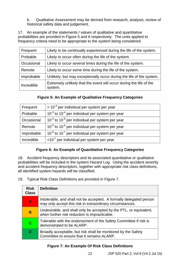
17. An example of the statements / values of qualitative and quantitative probabilities are provided in Figure 5 and 6 respectively. The units applied to frequency criteria need to be appropriate to the system being considered.
Frequent Likely to be continually experienced during the life of the system.
Probable Likely to occur often during the life of the system.
Occasional Likely to occur several times during the life of the system.
Remote Likely to occur some time during the life of the system.
Improbable Unlikely, but may exceptionally occur during the life of the system.
Incredible Extremely unlikely that the event will occur during the life of the system.
Figure 5: An Example of Qualitative Frequency Categories
Frequent > 10-3 per individual per system per year
Probable 10-3 to 10-4 per individual per system per year
Occasional 10-4 to 10-5 per individual per system per year
Remote 10-5 to 10-6 per individual per system per year
Improbable 10-6 to 10-7 per individual per system per year
Incredible <10-7 per individual per system per year
Figure 6: An Example of Quantitative Frequency Categories
18. Accident frequency descriptors and its associated quantitative or qualitative probabilities will be included in the system Hazard Log. Using the accident severity and accident frequency descriptors, together with appropriate risk class definitions, all identified system hazards will be classified.
19. Typical Risk Class Definitions are provided in Figure 7.
Risk Class
Definition
A Intolerable, and shall not be accepted. A formally delegated person may only accept this risk in extraordinary circumstances.
B Undesirable, and shall only be accepted by the PTL, or equivalent, when further risk reduction is impracticable.
C Tolerable with the endorsement of the Safety Committee if risk is demonstrated to be ALARP.
D Broadly acceptable, but risk shall be monitored by the Safety Committee to ensure that it remains ALARP.
Figure 7: An Example Of Risk Class Definitions

JSP 520 Part 2, Vol 8 (V4.2 Jul 15) 13
20. The criteria in Figures 3 to 7 are purely illustrative. The criteria used for any specific OME system will be derived from an appropriate comparator. Where this information is not available HSE guidelines, as detailed in the publication Reducing risks, Protecting People15, should be considered. Safety targets can be set by using information from internal sources such as historic information on similar or like systems or external sources such as HSE, industry best practice, engineering judgement etc, and may be as simple as a series of verbal statements providing a boundary of what is acceptable.
21. When working on Projects with Partner Nations, e.g. Germany, France, etc. the tolerability criteria will need to be agreed by all Partners. In doing this, the approach may differ from the MOD’s recognised good practice. Thus, the PT will need to demonstrate how they will manage any deviations identified.
22. It should be remembered that whichever method is used qualitative or quantitative, demonstration that a target has been achieved, or bettered, may not always be practicable. It should be used to indicate the level of performance / integrity expected from the system, and as a baseline against which to argue the Safety Case.
15 Reducing risks, protecting people. HSE’s decision-making process (2001).
JSP 520 Part 2, Vol 8 (V4.2 Jul 15) 14
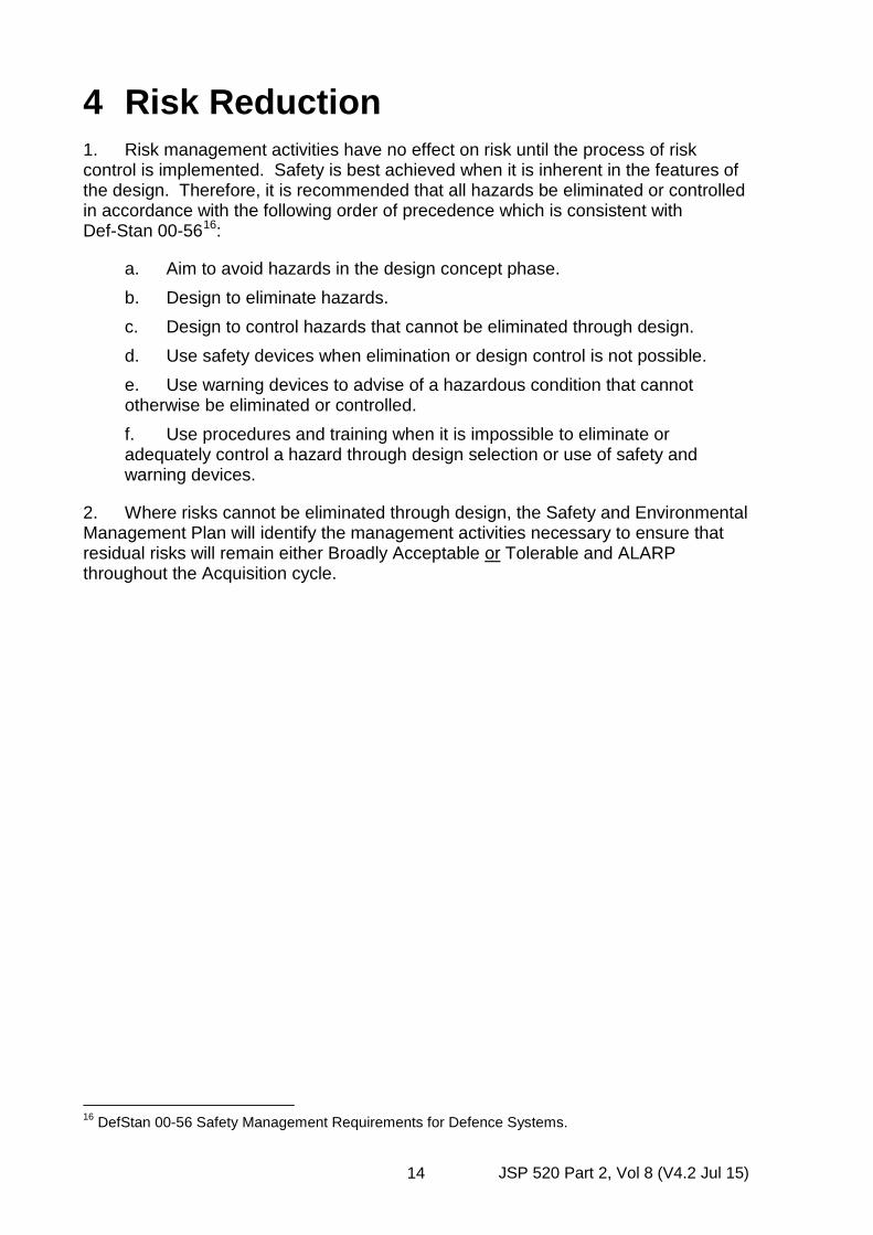
4 Risk Reduction 1. Risk management activities have no effect on risk until the process of risk control is implemented. Safety is best achieved when it is inherent in the features of the design. Therefore, it is recommended that all hazards be eliminated or controlled in accordance with the following order of precedence which is consistent with Def-Stan 00-5616:
a. Aim to avoid hazards in the design concept phase. b. Design to eliminate hazards. c. Design to control hazards that cannot be eliminated through design. d. Use safety devices when elimination or design control is not possible. e. Use warning devices to advise of a hazardous condition that cannot otherwise be eliminated or controlled. f. Use procedures and training when it is impossible to eliminate or adequately control a hazard through design selection or use of safety and warning devices.
2. Where risks cannot be eliminated through design, the Safety and Environmental Management Plan will identify the management activities necessary to ensure that residual risks will remain either Broadly Acceptable or Tolerable and ALARP throughout the Acquisition cycle.
16 DefStan 00-56 Safety Management Requirements for Defence Systems.
JSP 520 Part 2, Vol 8 (V4.2 Jul 15) 15
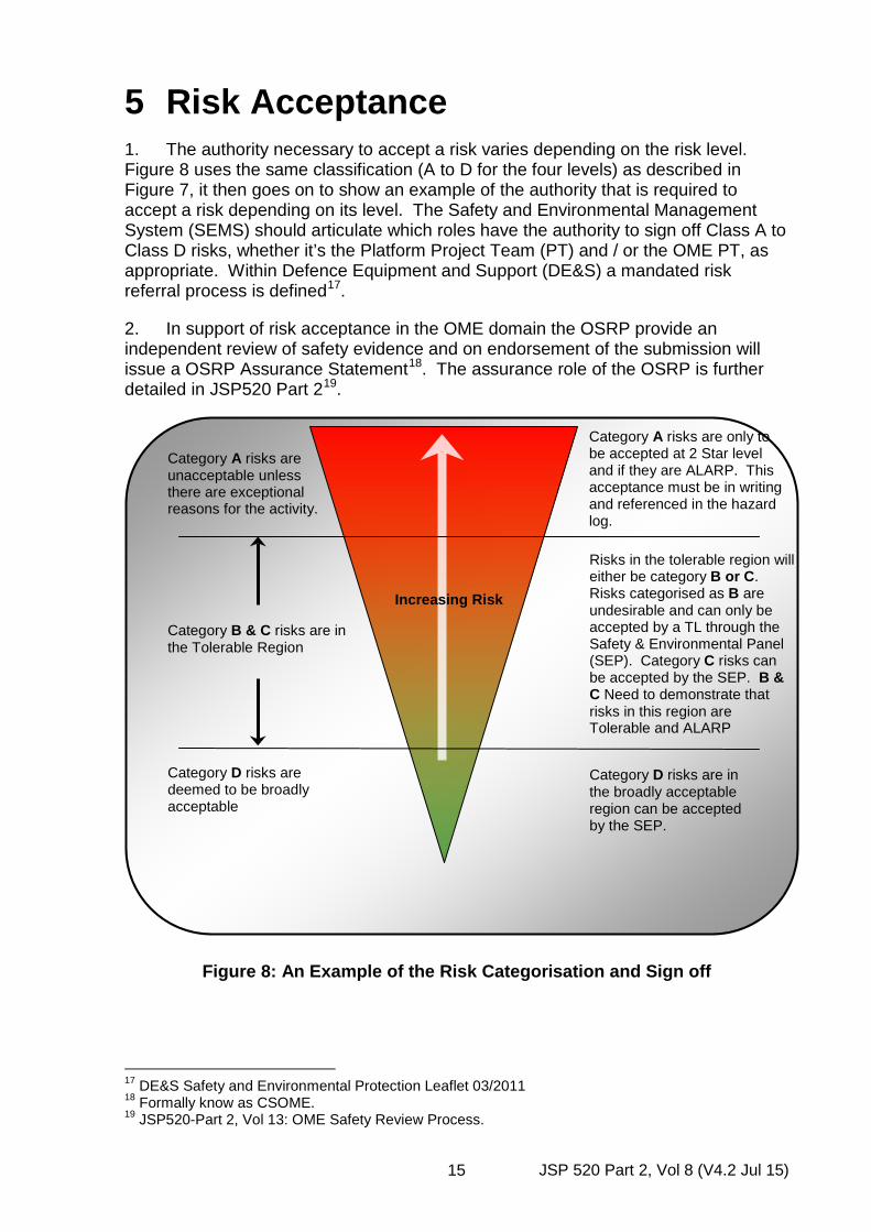
5 Risk Acceptance 1. The authority necessary to accept a risk varies depending on the risk level. Figure 8 uses the same classification (A to D for the four levels) as described in Figure 7, it then goes on to show an example of the authority that is required to accept a risk depending on its level. The Safety and Environmental Management System (SEMS) should articulate which roles have the authority to sign off Class A to Class D risks, whether it’s the Platform Project Team (PT) and / or the OME PT, as appropriate. Within Defence Equipment and Support (DE&S) a mandated risk referral process is defined17.
2. In support of risk acceptance in the OME domain the OSRP provide an independent review of safety evidence and on endorsement of the submission will issue a OSRP Assurance Statement18. The assurance role of the OSRP is further detailed in JSP520 Part 219.
Figure 8: An Example of the Risk Categorisation and Sign off
17 DE&S Safety and Environmental Protection Leaflet 03/2011 18 Formally know as CSOME. 19 JSP520-Part 2, Vol 13: OME Safety Review Process.
Increasing Risk
Category A risks are unacceptable unless there are exceptional reasons for the activity.
Category B & C risks are in the Tolerable Region
Category D risks are deemed to be broadly acceptable
Category A risks are only to be accepted at 2 Star level and if they are ALARP. This acceptance must be in writing and referenced in the hazard log.
Risks in the tolerable region will either be category B or C. Risks categorised as B are undesirable and can only be accepted by a TL through the Safety & Environmental Panel (SEP). Category C risks can be accepted by the SEP. B & C Need to demonstrate that risks in this region are Tolerable and ALARP
Category D risks are in the broadly acceptable region can be accepted by the SEP.

JSP 520 Part 2, Vol 8 (V4.2 Jul 15) 16
6 Operational Risk 1. Commanders should be provided with equipment that is safe for its intended military role and with adequate information to enable them to make sound risk based decisions when on operations. A system should be safe in training, during peacetime and on operations.
2. However, it may not always be possible to remain within the PT defined Safe Operating Envelope (SOE) in times of hostility. Operations outside of the SOE may need to be carried out if, in the judgement of the appropriate Operating Authority or Commanding Officer, the operational benefits outweigh the increased risk to safety. It is the PT’s responsibility to ensure that safety issues, i.e. emergency and contingency arrangements and limitations of use etc., are clearly reflected in the relevant equipment publications to allow the Operating Authority or Commanding Officer to make such an informed decision if they decide to take this course of action.

JSP 520 Part 2, Vol 8 (V4.2 Jul 15) 17
7 Software Safety 1. The MOD has a legal obligation to ensure the safety of its OME throughout the acquisition cycle. OME is becoming increasingly reliant on electronic systems to deliver advanced capability. Consequently, the safe operation of OME depends on the electronics and the software components performing as required.
2. Software can only fail in a systematic manner i.e. due to its design it will always fail in the same way if it gets the same inputs. Software does not fail in a random manner i.e. it does not wear out. Therefore repeated testing is not necessarily going to find the fault scenario, and if the fault scenario was known then it would have been designed out before testing.
3. The challenge is to design the system in such a way as to prevent dangerous failures or to control them when they arise. Dangerous failures may arise from, for example:
a. Incorrect specifications of the system, hardware or software. b. Omissions in the safety requirements specification (e.g. failure to develop all relevant safety functions during different modes of operation). c. Random hardware failure mechanisms. d. Systematic hardware failure mechanisms. e. Software errors. f. Common cause failures (e.g. human error). g. Environmental influences (e.g. electromagnetic, temperature, mechanical phenomena). h. Supply system voltage disturbances (e.g. loss of supply, reduced voltages, re-connection of supply).
4. OME based on electronics and software has the potential to exhibit behaviour that is subtle or difficult to predict. Where such behaviour may have an impact on safety, action will be taken to reduce this potential. As a result, a rigorous approach to both the managerial and technical aspects of the software development process is essential. An effective approach to improving the integrity of software should not only result in increased safety but it is also likely to improve the effectiveness of the equipment.
5. Within OME like any other domain there is no pre-set safety integrity level pre assigned to functions of a munition or ordnance, rather the integrity required from a software function is determined through hazard analysis. A system level hazard analysis is therefore the essential starting point for all projects. This should identify those functions / sub-systems that are performing safety related actions. From this the degree of safety to be invested in software can be determined and the necessary processes can be defined and agreed.
6. In addition to software, Complex Electronic Elements (CEE) or Devices (CED) is a phrase that includes various types of semiconductor hardware whose functionality is defined / programmed using a software process. This step has been made because various hardware devices such as Field Programmable Gate Arrays
JSP 520 Part 2, Vol 8 (V4.2 Jul 15) 18
(FPGA) and Application Specific Integrated Circuits (ASICs) now have so many inputs they also cannot be 100% tested making them ‘software like’. Within OME projects the design authority will quite often design a function in hardware rather than software to reduce the development overhead and risk. However where a CEE is used the safety proving process can be as intensive as for software so the type of hardware to be used needs to be understood.
7. Several publications are available to assist in the appropriate development of safe software although the top level standard for UK MOD is DefStan 00-56 20. The use of other publications would be to ensure compliance against this standard. These publications are allowed / encouraged under the current issue of DefStan 00-56.
8. Allied Ordnance Publication (AOP) 5221. This is not a compliance document but is the primary guidance to be followed when considering software safety in relation to OME. AOP-52 is not intended to supersede policy, standard, or guidance pertaining to system safety, (e.g. DefStan 00-56 in the UK, and MIL-STD-88222 in the US, or software engineering and development standards). The purpose of AOP-52 is to provide management and engineering guidelines to achieve a reasonable level of assurance that the software will execute within the system context and operational environment with an acceptable level of safety risk.
9. European standard BS EN 6150823is a commercial standard that can be employed when considering the use of electrical / electronic / programmable systems to carry out Safety Related functions. This standard was borne out of the process industry and has a slant towards protection mechanisms, but where appropriate it can be used.
10. DO-178B24 is a best practice guide used by the aviation industry, as a standard for the development of computerised avionics. This is domain targeted at airborne systems, but again can be used where appropriate for autonomous real time Safety Related processing.
20 DefStan 00-56 Safety Management Requirements for Defence Systems 21 AOP52: Guidance on Software Safety Design and Assessment of Munition-Related Computing Systems. 22 MIL-STD-882 Revision D Department Of Defense Standard Practice For System Safety. 23 BS EN 61508 Functional safety of electrical/electronic/programmable electronic safety-related systems. 24 DO-178B: Software Considerations in Airborne Systems and Equipment Certification, circa 1992.