risk assessment report -...
TRANSCRIPT

1
RISK ASSESSMENT REPORTfor
“PROPOSED EXPANSION OF BULK DRUGS,INTRERMEDIATES AND R&D PRODUCTS”
at
M/s. SAI LIFE SCIENCES LTD
KIADB INDUSTRIAL AREAVillage : KOLHAR
Taluk : BIDARDistrict : BIDAR
State : KARNATAKA(Project termed under Schedule 5(f), Category B, Synthetic
Organic Chemicals)
PREPARED BYHUBERT ENVIRO CARE SYSTEMS (P) LTD
CHENNAI
MARCH 2017

2
TABLE OF CONTENTS
1 INTRODUCTION ................................................................................................................................4
1.1 PURPOSE OF THE REPORT ...................................................................................................... 4
1.2 SCOPE OF THE STUDY .............................................................................................................4
1.3 METHODOLOGY ADOPTED .................................................................................................... 4
2 RISK ASSESSMENT METHODOLOGY ...........................................................................................5
2.1 IDENTIFICATION OF HAZARDS & RELEASE SCENARIOS ...............................................5
2.1.1 FACTORS CONSIDERED FOR IDENTIFICATION OF HAZARDS ...............................5
3 CONSEQUENCE ANALYSIS...........................................................................................................11
3.1 SCENARIOS POSSIBLE ...........................................................................................................11
3.2 WEATHER PROBABILITIES...................................................................................................11
3.2.1 WIND VELOCITY & STABILITY CLASS......................................................................11
3.2.2 WEATHER INPUT ............................................................................................................11
3.3 ACCIDENT SCENARIOS FOR THIS PROJECT.....................................................................12
3.3.1 Consequence analysis for solvent storage tank ...................................................................12
3.4 SUMMARY OF RESULTS AND OBSERVATIONS.............................................................108
4 MITIGATIVE MEASURES.............................................................................................................109
4.1 SUMMARY OF RISK ANALYSIS AND FINDINGS............................................................109
4.2 RECOMMENDATIONS FOR IMPROVING SAFETY..........................................................109

3
LIST OF TABLESTable 2.1 Chemical properties and classification .........................................................................................6Table 2.2 Damages to Human Life Due to Heat Radiation ..........................................................................8Table 2.3 Effects Due To Incident Radiation Intensity.................................................................................9Table 3.1 Pasquill – Giffard Atmospheric Stability....................................................................................11Table 3.2 Atmospheric data (Manual Input for the worst scenario) ...........................................................12Table 3.3 Input details of solvent storage tank ...........................................................................................12Table 3.4 Consequence analysis for Solvent Storage Tanks.......................................................................13Table 3-5 Chemical flowing from underground Storage tank to reaction tank pipeline details .................68Table 3-6: Estimated distance due to failure of Storage tank pipeline........................................................69
4
1 INTRODUCTION
1.1 PURPOSE OF THE REPORT
The purpose of the study is to identify and assess those hazards and risks arising from
Proposed Expansion of Bulk Drugs, Intermediates and R&D Products at plot no. 79/B, 80A,
80B, 81A & 82, and Sy. No. 280, Kolhar Industrial Area, KIADB, Bidar District, Karnataka
State.
1.2 SCOPE OF THE STUDY
Hazard Identification and Risk Analysis including identification, screening of scenarios,
consequence analysis of the various risk scenarios, recommendation and preparation of
reports and relevant drawing showing damage and risk contours.
The scope of the study mainly involves:
Identifications of Hazards
Consequence modelling
Flammable area of Vapour cloud explosion modelling
Jet Fire
Pool fire analysis
Dispersion of vapour cloud analysis
Impact limits identifications
Contour mapping of the risk on the layouts.
Mitigating measures for handling and storage to reduce impacts & prevent incidents.
1.3 METHODOLOGY ADOPTED
The Risk Assessment is been carried out by using the ALOHA software (Aerial Locations
of Hazardous Atmospheres) & PHAST.

5
2 RISK ASSESSMENT METHODOLOGY
2.1 IDENTIFICATION OF HAZARDS & RELEASE SCENARIOS
A technique commonly used to generate an incident list is to consider potential leaks,
ruptures and fractures of all process pipelines and vessels/tanks. The following data were
collected to envisage scenarios:
Solvent Tank conditions (phase, temperature, pressure) and dimensions.
Pipelines connected from storage tanks to reaction process
2.1.1 FACTORS CONSIDERED FOR IDENTIFICATION OF HAZARDS
In any installation, main hazard arises due to loss of containment during handling of
flammable and toxic chemicals. The Chemicals are classified according to the properties and
hazard class given by National Fire Protection Association (NFPA) is responsible for 300
consensus codes and standards intended to eliminate death, injury, property and economic
loss due to fire, electrical and related hazards.
NFPA classification for Health, Flammability & Reactivity of a chemical is on a scale from
0-4 least to worst. As per the NFPA Rating on the scale from 0-4 the chemicals having 3 &
4 are considered are highly hazardous and considered for analysis.
Health Fire
0-No hazard 0-will not burn
1-can cause significant irritation 1- must be preheated before ignition occur
2-can cause temporary incapacitation or
residual injury
2-must be heated or high ambient temperature
to burn
3-can cause serious or permanent injury 3- can be ignited under almost all ambient
4-can be lethal 4-will vaporize and readily burn at normal
temp
The proposed chemicals list are mentioned in Table 2.1:

6
Table 2.1 Chemical properties and classification
S.No Tank
Name
Solvent Boiling
Point
(°C)
Flash
point
(°C)
NFPA Rating
Fire Health Reactivity
1 T 1 Hexane 68 -22.5 3 1 0
2 T 2 IsoPropylAlcohol 82 12 3 1 0
3 T 3 Cyclo Hexane 80.55 -20 3 1 0
4 T 4 Methanol 64.7 12 3 1 0
5 T 5 Acetone 56.11 -17.8 3 1 0
6 T 6 Dichloromethane 39.78 - 1 2 0
7 T 7 Ethyl acetate 77.22 -3.0 3 1 1
8 T 8 Toluene 110.55 7 3 2 0
9 T 9 N-Heptane 98.33 -3.9 3 1 0
10 RS 01 Ethanol 78.33 40 3 2 0
The fire hazard is considered for all the solvents except the Dichloromethane in which the
fire hazard is minimum. The health hazard is not observed in any solvent.
2.2 TYPES OF OUTCOME EVENTS
In this section of the report we describe the probabilities associated with the sequence of
occurrences which must take place for the incident scenarios to produce hazardous effects
and the modelling of their effects.
Considering the present case the outcomes expected are
- Jet fire
- Flash Fire
- Vapour Cloud Explosion (VCE)
- Pool Fire
JET FIRE
Jet fire occurs when a pressurized release (of a flammable gas or vapour) is ignited by any
source. They tend to be localized in effect and are mainly of concern in establishing the
potential for domino effects and employee safety zones rather than for community risks.

7
The jet fire model is based on the radiant fraction of total combustion energy, which is
assumed to arise from a point slowly along the jet flame path. The jet dispersion model
gives the jet flame length.
FLASH FIRE
A flash fire is the non-explosive combustion of a vapour cloud resulting from a release of
flammable material into the open air, which after mixing with air, ignites. A flash fire results
from the ignition of a released flammable cloud in which there is essentially no increase in
combustion rate. The ignition source could be electric spark, a hot surface, and friction
between moving parts of a machine or an open fire. Part of the reason for flash fires is that,
flammable fuels have a vapour temperature, which is less than the ambient Temperature.
Hence, as a result of a spill, they are dispersed initially by the negative buoyancy of cold
vapours and subsequently by the atmospheric turbulence. After the release and dispersion of
the flammable fuel the resulting vapour cloud is ignited and when the fuel vapour is not
mixed with sufficient air prior to ignition, it results in diffusion fire burning. Therefore the
rate at which the fuel vapour and air are mixed together during combustion determines the
rate of burning in the flash fire.
The main dangers of flash fires are radiation and direct flame contact. The size of the
flammable cloud determines the area of possible direct flame contact effects. Radiation
effects on a target depend on several factors including its distance from the flames, flame
height, flame emissive power, local atmospheric transitivity and cloud size.
VAPOUR CLOUD EXPLOSION (VCE)
Vapour cloud explosion is the result of flammable materials in the atmosphere, a subsequent
dispersion phase, and after some delay an ignition of the vapour cloud. Turbulence is the
governing factor in blast generation, which could intensify combustion to the level that will
result in an explosion. Obstacles in the path of vapour cloud or when the cloud finds a
confined area, as under the bullets, often create turbulence. Insignificant level of
confinement will result in a flash fire. The VCE will result in overpressures.
It may be noted that VCE’s have been responsible for very serious accidents involving
severe property damage and loss of lives.

8
POOL FIRE
This represents a situation when flammable liquid spillage forms a pool over a liquid or
solid surface and gets ignited. Flammable liquids can be involved in pool fires where they
are stored and transported in bulk quantities. Early pool fire was caused when the steady
state is reached between the outflow of flammable material from the container and complete
combustion of the flammable material when the ignition source is available. Late pool fires
are associated with the difference between the release of material and the complete
combustion of the material simultaneously. Late pool fires are common when large quantity
of flammable material is released within short time.
2.3 Heat Radiation
The effect of fire on a human being is in the form of burns. There are three categories of
burn such as first degree, second degree and third degree burns. The consequences caused
by exposure to heat radiation are a function of:
The radiation energy onto the human body [kW/m2];
The exposure duration [sec];
The protection of the skin tissue (clothed or naked body).
The limits for 1% of the exposed people to be killed due to heat radiation, and for second-
degree burns are given in the table below:
Table 2.2 Damages to Human Life Due to Heat Radiation
Exposure Duration Radiation energy
(1% lethality,
kW/m2)
Radiation energy for
2nd degree burns,
kW/m2
Radiation energy for
first degree burns,
kW/m2
10 sec 21.2 16 12.5
30 sec 9.3 7 4

9
Table 2.3 Effects Due To Incident Radiation Intensity
INCIDENT RADIATION
– kW/m2
TYPE OF DAMAGE
0.7 Equivalent to Solar Radiation
1.6 No discomfort for long exposure
4.0 Sufficient to cause pain within 20 sec. Blistering of skin (first
degree burns are likely)
9.5 Pain threshold reached after 8 sec. second degree burns after
20 sec.
12.5 Minimum energy required for piloted ignition of wood,
melting plastic tubing’s etc.
37.5 Heavy Damage to process equipment
TYPE OF DAMAGE
The actual results would be less severe due to the various assumptions made in the models
arising out of the flame geometry, emissivity, angle of incidence, view factor and others. The
radiative output of the flame would be dependent upon the fire size, extent of mixing with air and
the flame temperature. Some fraction of the radiation is absorbed by carbon dioxide and water
vapour in the intervening atmosphere. Finally the incident flux at an observer location would
depend upon the radiation view factor, which is a function of the distance from the flame surface,
the observer’s orientation and the flame geometry.
Assumptions made for the study (As per the guidelines of CPR 18 E Purple Book)
The lethality of a jet fire is assumed to be 100% for the people who are caught in the flame.
Outside the flame area, the lethality depends on the heat radiation distances.
For the flash fires lethality is taken as 100% for all the people caught outdoors and for 10%
who are indoors within the flammable cloud. No fatality has been assumed outside the flash
fire area.

10
Explosion
In case of vapour cloud explosion, two physical effects may occur:
_ A flash fire over the whole length of the explosive gas cloud;
_ A blast wave, with typical peak overpressures circular around ignition source.
For the blast wave, the lethality criterion is based on:
A peak overpressure of 0.1bar will cause serious damage to 10% of the housing/structures.
Falling fragments will kill one of each eight persons in the destroyed buildings.
The following damage criteria may be distinguished with respect to the peak overpressures
resulting from a blast wave:
Peak Overpressure Damage Type Description
0.30 bar Heavy Damage Major damage to plant equipment
structure
0.10 bar Moderate Damage Repairable damage to plant
equipment & structure
0.03 bar Significant Damage Shattering of glass
0.01 bar Minor Damage Crack in glass
Assumptions for the study (As per the guidelines of CPR 18 E Purple Book)
Overpressure more than 0.3 bar corresponds approximately with 50% lethality.
An overpressure above 0.2 bar would result in 10% fatalities.
An overpressure less than 0.1 bar would not cause any fatalities to the public.
100% lethality is assumed for all people who are present within the cloud proper.

11
3 CONSEQUENCE ANALYSIS
3.1 SCENARIOS POSSIBLE
As large number of failure cases can lead to the same type of consequences, representative
failure cases are selected for this analysis. The failure cases are based on conservative
assumptions. The scenarios are discussed one at a time.
3.2 WEATHER PROBABILITIES
3.2.1 WIND VELOCITY & STABILITY CLASS
As per CPR 18E there are 6 representative weather classes:
Table 3.1 Pasquill – Giffard Atmospheric Stability
S.No. Stability Class Weather Conditions
1 A Very unstable - Sunny, light wind
2 A/B Unstable - as with A only less sunny or more windy
3 B Unstable - as with A/B only less sunny or more windy
4 B/C Moderately unstable – moderate sunny and moderate wind
5 C Moderately unstable – very windy / sunny or overcast / light wind
6 C/D Moderate unstable – moderate sun and high wind
7 D Neutral – little sun and high wind or overcast / windy night
8 E Moderately stable – less overcast and less windy night
9 F Stable – night with moderate clouds and light / moderate wind
10 G Very stable – possibly fog
3.2.2 WEATHER INPUT
The details of the risk assessment is given below

12
Table 3.2 Atmospheric data (Manual Input for the worst scenario)
Average Wind speed (m/s) 1.5
Stability Class 1.5/F, 5/D and 1.5/D
Wind Direction South West to North East
Temp (Celsius) 31.6
Humidity (%) 66
Source IMD
3.3 ACCIDENT SCENARIOS FOR THIS PROJECT
3.3.1 Consequence analysis for solvent storage tank
Table 3.3 Input details of solvent storage tank
S. NoDia(m)
length(m)
Volume(m3)
InternalTemperature
(0c)Solvents
1. 2.6 4.0 20 32 Hexane
2. 2.6 4.0 20 32 Iso Propyl Alcohol
3. 2.6 4.0 20 32 Cyclo Hexane
4. 2.6 4.0 20 32 Methanol
5. 2.6 4.0 20 32 Acetone
6. 2.6 4.0 20 32 Ethyl Acetate
7. 2.6 4.0 20 32 Toluene
8. 2.6 4.0 20 32 N - Heptane
9. 2.3 3.2 12 32 Ethanol

13
Table 3.4 Consequence analysis for Solvent Storage Tanks
S.No Description Event Impact criteria Consequence Distance (m)
Category1.5/F
Category5/D
Category1.5/D
1 Leak of n-Hexane Storagetank
Dispersion of vaporcloud (VCE)
5250 ppm 27 11.19 29.16
Jet Fire 4 kW/m2 17.32 14.61 17.36
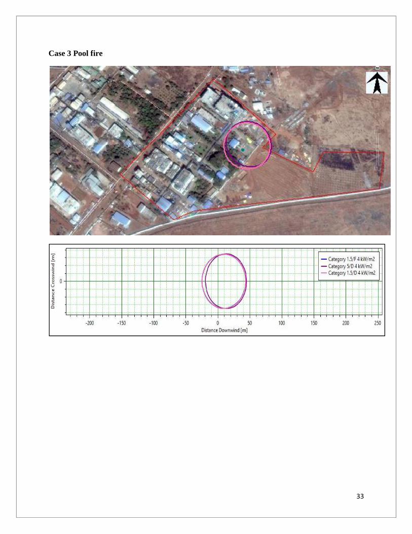
Pool fire 4 kW/m2 13.07 14.11 13.12
Flash Fire 5250 ppm 26.99 13.75 29.15
Late Explosion worstcase radii
0.02068 bar 66.91 30.34 56.58
2 Catastrophic rupture of n-Hexane Storage tank
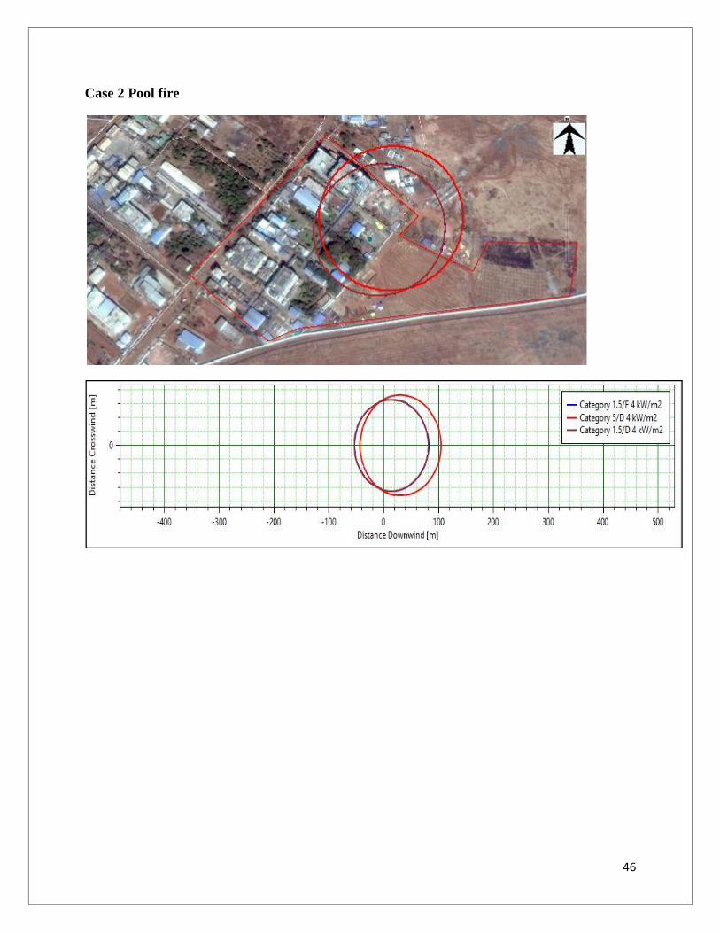
Pool fire 4 kW/m2 75.79 99.4 75.34
3 Leak of Isopropyl alcoholStorage tank
Dispersion of vaporcloud (VCE)
10000 ppm 63.46 29.81 63.33
Jet Fire 4 kW/m2 21.69 19.07 21.88
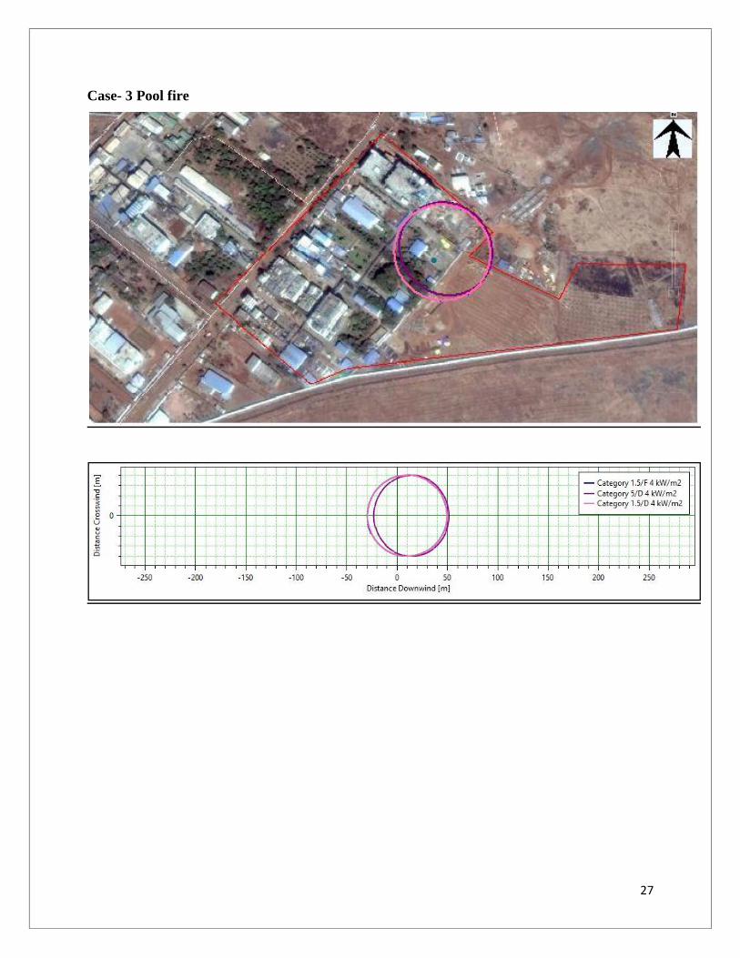
Pool fire 4 kW/m2 49.65 51.38 49.65
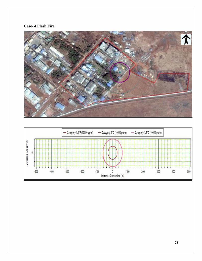
Flash Fire 10000 ppm No explosion 29.45 63.21

14
S.No Description Event Impact criteria Consequence Distance (m)
Category1.5/F
Category5/D
Category1.5/D
4 Catastrophic rupture ofIsopropyl alcohol Storagetank
Dispersion of vaporcloud (VCE)
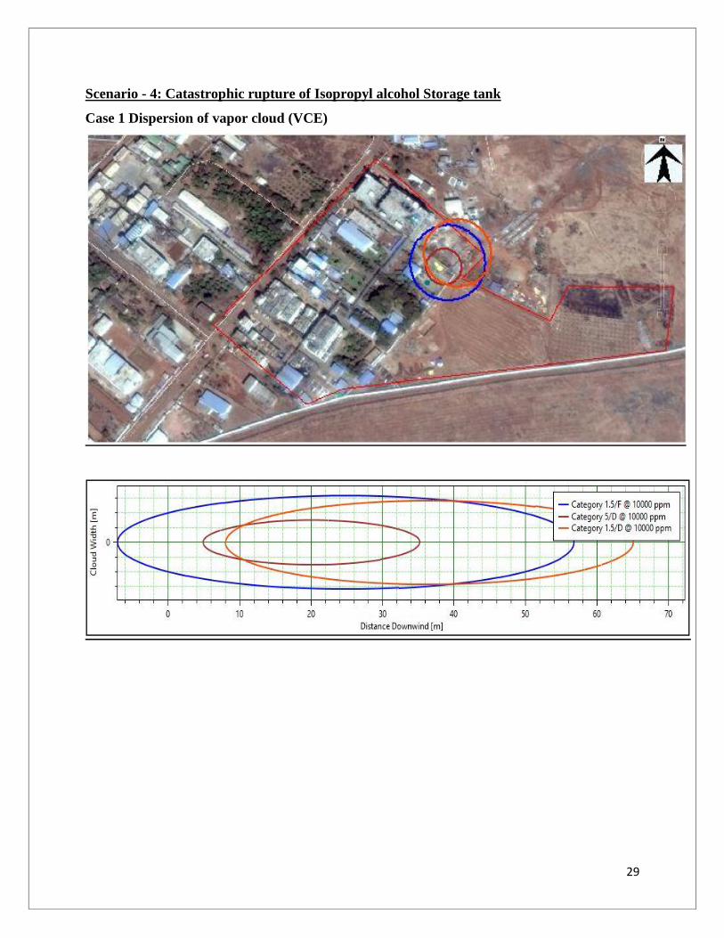
10000 ppm 56.68 35.15 65.02
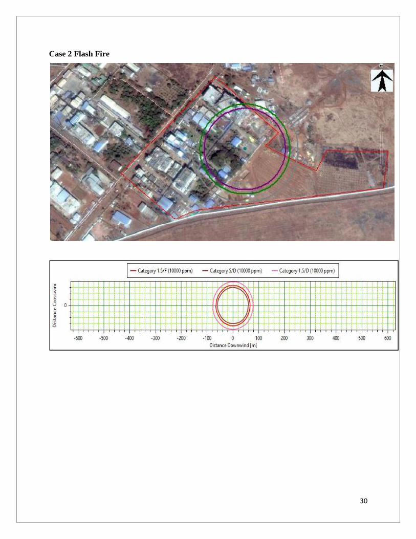
Flash Fire 10000 ppm 65.73 59.46 78.05
5 Leak of Methanol Storagetank
Dispersion of vaporcloud (VCE)
36500 ppm 55.16 18.39 36.86
Jet Fire 4 kW/m2 29.39 25.31 29.63
Pool fire 4 kW/m2 43.19 44.72 43.19
Flash Fire 36500 ppm 55.97 22.89 35.98
6 Catastrophic rupture ofMethanol Storage tank
Dispersion of vaporcloud (VCE)
36500 ppm 85.74 28.56 45.11
Pool fire 4 kW/m2 90.56 93.81 90.36
7 Leak of Acetone Storagetank
Dispersion of vaporcloud (VCE)
13000 ppm 50.05 29.05 52.78
Jet Fire 4 kW/m2 23.77 20.08 23.83
Pool fire 4 kW/m2 27.58 29.04 27.59
Flash Fire 13000 ppm 50.02 28.92 52.75

15
S.No Description Event Impact criteria Consequence Distance (m)
Category1.5/F
Category5/D
Category1.5/D
8 Leak of Toluene Storagetank
Dispersion of vaporcloud (VCE)
6000 ppm 42.13 24.81 43.09
Jet Fire 4 kW/m2 9.85 8.42 9.9
Pool fire 4 kW/m2 27.77 29.87 27.79
Flash Fire 6000 ppm 42.11 24.8 42.75
Late Explosion worstcase radii
0.02068 bar 58.26 27.82 49.8
9 Catastrophic rupture ofToluene Storage tank
Dispersion of vaporcloud (VCE)
6000 ppm 55.89 31.89 59.58
Pool fire 4 kW/m2 81.69 104.13 81.59
Flash Fire 6000 ppm 60.27 56.79 72.23
10 Leak of N-HeptaneStorage tank
Jet Fire 4 kW/m2 24.18 21.7 24.35
Pool fire 4 kW/m2 35.89 39.76 35.93
Flash Fire 5000 ppm 83.18 39.91 85.98
11 Catastrophic rupture of N-Heptane Storage tank
Dispersion of vaporcloud (VCE)
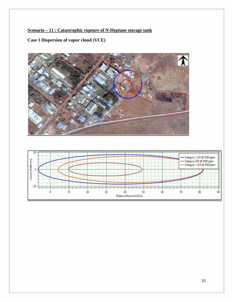
5000 ppm 81.83 49.07 81.58

16
S.No Description Event Impact criteria Consequence Distance (m)
Category1.5/F
Category5/D
Category1.5/D
Flash Fire 5000 ppm 86.95 71.56 110.83
12 Leak of Ethanol Storagetank
Dispersion of vaporcloud (VCE)
21500 ppm 45.24 18.69 42.29
Jet Fire 4 kW/m2 19.92 17.22 20.07
Pool fire 4 kW/m2 44.92 46.53 44.94
Flash Fire 21500 ppm 44.88 18.74 42.27
13 Catastrophic rupture ofEthanol Storage tank
Dispersion of vaporcloud (VCE)
21500 ppm 43.01 21.81 48.02
Flash Fire 21500 ppm 46.73 44.67 58.4

17
S.No Scenarios Event Impact Conc. Distance covered
by Solvent Tank
(m)
Effects
14 Leak of Cyclo Hexane
Storage tank
Thermal
radiation from
Pool Fire
Red (High) 10 Kw/(sq.m) <10 Potentially Lethal within 60sec
Orange
(Medium)
5 Kw/(sq.m) 13 2nd degree burns within 60sec
Yellow (Low) 2 Kw/(sq.m) 23 Pain within 60sec
Dispersion of
vapor cloud
(VCE)
Red (High) 10000 ppm 17 PAC-3
Orange
(Medium)
1700 ppm 44 PAC-2
Yellow (Low) 300 ppm 113 PAC-1
15 Catastrophic rupture of
Cyclo Hexane Storage
tank
Thermal
radiation from
Pool Fire
Red (High) 10 Kw/(sq.m) 71 Potentially Lethal within 60sec
Orange
(Medium)
5 Kw/(sq.m) 102 2nd degree burns within 60sec
Yellow (Low) 2 Kw/(sq.m) 160 Pain within 60sec
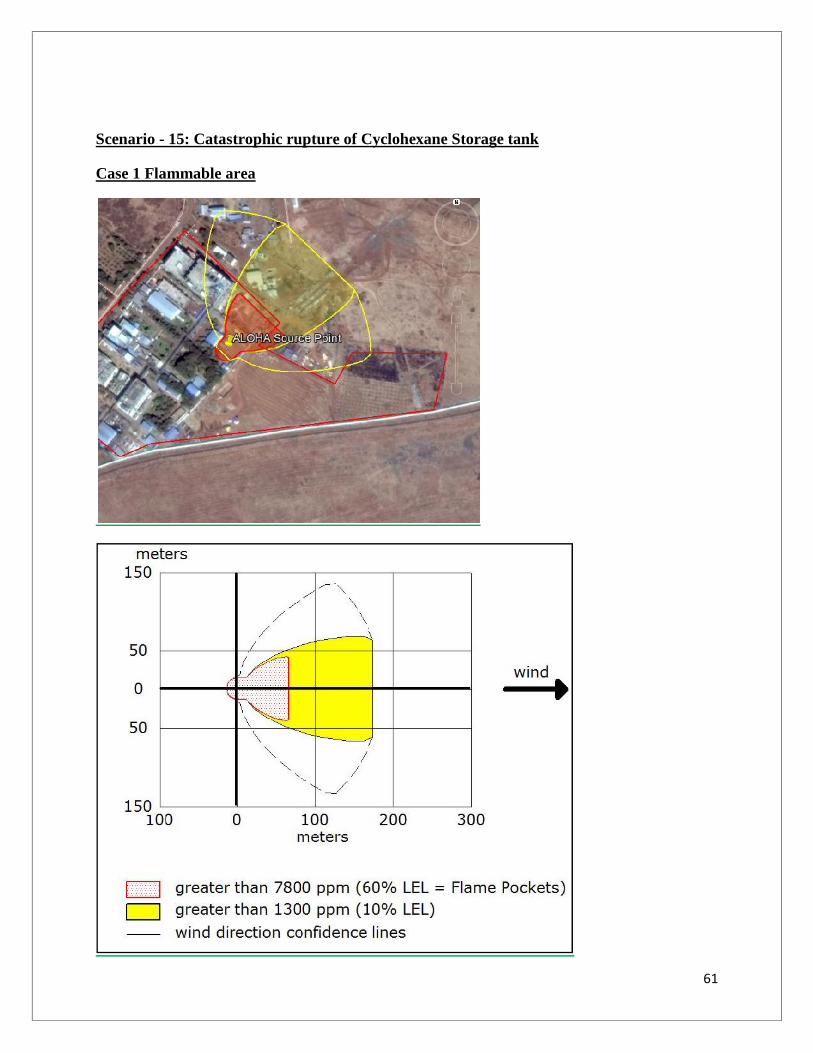
Flammable
area of vapor
cloud
Red 7800 ppm 66 60% LEL = Flame Pockets
Yellow 1300 ppm 174 10% LEL
16 Leak of Ethyl acetate
Storage tank
Dispersion of
vapor cloud
(VCE)
Red (High) 10000 ppm 22 PAC-3
18
S.No Scenarios Event Impact Conc. Distance covered
by Solvent Tank
(m)
Effects
Orange
(Medium)
1700 ppm 57 PAC-2
Yellow (Low) 1200 ppm 69 PAC-1
Flammable
area of vapor
cloud
Red 13080 ppm 20 60% LEL = Flame Pockets
Yellow 2180 ppm 52 10% LEL
Thermal
radiation from
Pool Fire
Red (High) 10 Kw/(sq.m) <10 Potentially Lethal within 60sec
Orange
(Medium)
5 Kw/(sq.m) 11 2nd degree burns within 60sec
Yellow (Low) 2 Kw/(sq.m) 19 Pain within 60sec
17 Catastrophic rupture of
Ethyl acetate Storage
tank
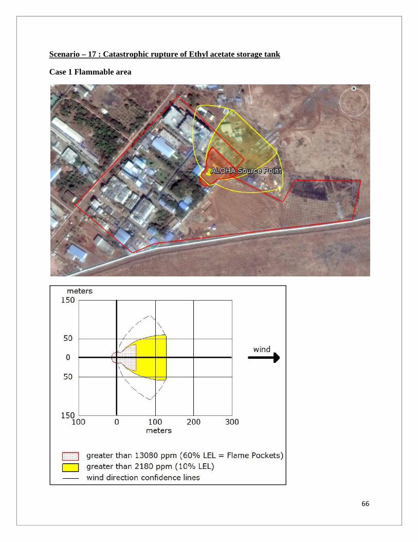
Flammable
area of vapor
cloud
Red 13080 ppm 50 60% LEL = Flame Pockets
Yellow 2180 ppm 129 10% LEL
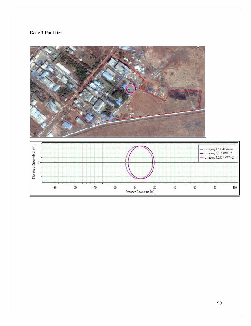
Thermal
radiation from
Pool Fire
Red (High) 10 Kw/(sq.m) 42 Potentially Lethal within 60sec
Orange
(Medium)
5 Kw/(sq.m) 60 2nd degree burns within 60sec
Yellow (Low) 2 Kw/(sq.m) 94 Pain within 60sec

19
CONTOUR MAPS
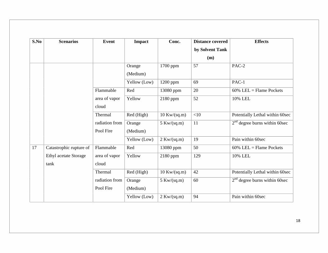
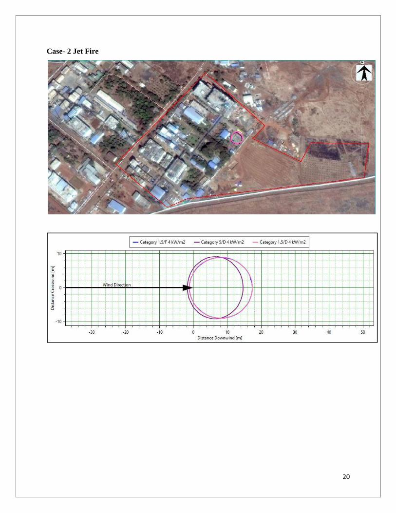
Scenario -1: Leak of n-Hexane storage tank
Case- 1 Dispersion of vapor cloud (VCE)
20
Case- 2 Jet Fire

21
Case- 3 Pool fire
22
Case- 4 Flash Fire

23
Case- 5 Late Explosion worst case radii

24
Scenario - 2: Catastrophic rupture of n-Hexane Storage tank
Case- 1 Pool fire

25
Scenario - 3: Leak of Isopropyl alcohol Storage tank
Case- 1 Dispersion of vapor cloud (VCE)

26
Case- 2 Jet Fire
27
Case- 3 Pool fire
28
Case- 4 Flash Fire
29
Scenario - 4: Catastrophic rupture of Isopropyl alcohol Storage tank
Case 1 Dispersion of vapor cloud (VCE)
30
Case 2 Flash Fire

31
Scenario - 5: Leak of Methanol Storage tank
Case 1 Dispersion of vapor cloud (VCE)

32
Case 2 Jet Fire
33
Case 3 Pool fire

34
Case 4 Flash Fire

35
Scenario - 6: Catastrophic rupture of Methanol Storage tank
Case 1 Dispersion of vapor cloud (VCE)

36
Case 2 Pool fire

37
Scenario - 7: Leak of Acetone Storage tank
Case 1 Dispersion of vapor cloud (VCE)

38
Case 2 Jet Fire

39
Case 3 Pool fire

40
Case 4 Flash Fire

41
Scenario 8: Leak of Toluene Storage tank
Case 1 Dispersion of vapor cloud (VCE)

42
Case 2 Jet Fire

43
Case 3 Pool fire

44
Case 4 Flash Fire

45
Scenario 9: Catastrophic rupture of Toluene Storage tank
Case 1 Dispersion of vapor cloud (VCE)
46
Case 2 Pool fire

47
Case 3 Flash Fire

48
Scenario – 10 : Leak of N-Heptane storage tank
Case 1 Jet fire

49
Case 2 Pool fire

50
Case 3 Flash fire
51
Scenario – 11 : Catastrophic rupture of N-Heptane storage tank
Case 1 Dispersion of vapor cloud (VCE)

52
Case 2 Flash fire

53
Scenario – 12 : Leak of Ethanol storage tank
Case 1 Dispersion of vapor cloud (VCE)

54
Case 2 Jet fire

55
Case 3 Pool fire

56
Case 4 Flash fire

57
Scenario – 13 : Catastrophic rupture of Ethanol storage tank
Case 1 Dispersion of vapor cloud (VCE)

58
Case 2 Flash fire

59
Scenario - 14: Leak of Cyclohexane Storage tank
Case 1 Toxic area of vapor cloud

60
Case 2 Pool fire
61
Scenario - 15: Catastrophic rupture of Cyclohexane Storage tank
Case 1 Flammable area

62
Case 2 Pool fire

63
Scenario - 16: Leak of Ethyl acetate storage tank
Case 1 Toxic area of vapor cloud

64
Case 2 Flammable area

65
Case 3 Pool fire
66
Scenario – 17 : Catastrophic rupture of Ethyl acetate storage tank
Case 1 Flammable area

67
Case 2 Pool fire

68
Table 3-5 Chemical flowing from underground Storage tank to reaction tank pipelinedetails
S.No PipeNo./Name
PipelineSize dia
(m)
Pipelinelength (m)
OperatingTemperature(oc)
Chemical flowing
1 T 1 0.0381 100 m 32 Hexane
2 T 2 0.0381 100 m 32 Isopropyl Alcohol
3 T 3 0.0381 100 m 32 Cyclo Hexane
4 T 4 0.0381 100 m 32 Methanol
5 T 5 0.0381 100 m 32 Acetone
6 T 6 0.0381 100 m 32 Dichloromethane
7 T 7 0.0381 100 m 32 Ethyl Acetate
8 T 8 0.0381 100 m 32 Toluene
9 T 9 0.0381 100 m 32 N - Heptane
10 RS 01 0.0381 50 m 32 Ethanol

69
Table 3-6: Estimated distance due to failure of Storage tank pipeline
S.No Description Event Impact criteria Consequence Distance (m)
Category1.5/F
Category5/D
Category1.5/D
1 Rupture of n-HexaneStorage tank pipeline(Pipe No. T1)
Dispersion of vaporcloud (VCE)
5250 ppm 36.67 26.38 40.13
Jet Fire 4 kW/m2 20.1 17.03 20.34
Pool fire 4 kW/m2 17.4 19.37 17.4
Flash Fire 5250 ppm 36.66 26.37 40.11
Late Explosion worstcase radii
0.02068 bar 135.8 60.04 136.47
2 Rupture of Isopropylalcohol Storage tankpipeline
(Pipe No. T2)
Dispersion of vaporcloud (VCE)
10000 ppm 13.88 10.32 16.18
Jet Fire 4 kW/m2 5.19 4.53 5.35
Pool fire 4 kW/m2 18.13 19.61 18.14
Flash Fire 10000 ppm 13.88 10.32 16.18
Late Explosion worstcase radii
0.02068 bar 53.82 24.69 45.59

70
S.No Description Event Impact criteria Consequence Distance (m)
Category1.5/F
Category5/D
Category1.5/D
3 Rupture of MethanolStorage tank pipeline
(Pipe No. T4)
Dispersion of vaporcloud (VCE)
36500 ppm 14.63 7.02 12.32
Jet Fire 4 kW/m2 8.11 6.01 8.3
Pool fire 4 kW/m2 15.15 16.53 15.17
Flash Fire 36500 ppm 14.59 7.05 12.31
Late Explosion worstcase radii
0.02068 bar 42.93 Noexplosion
34.88
4 Rupture of AcetoneStorage tank pipeline
(Pipe No. T5)
Dispersion of vaporcloud (VCE)
13000 ppm 29.41 19.19 31.25
Jet Fire 4 kW/m2 11.23 9.45 11.51
Pool fire 4 kW/m2 17.75 19.48 17.76
Flash Fire 13000 ppm 29.39 19.19 31.23
Late Explosion worstcase radii
0.02068 bar 102.21 36.53 109

71
S.No Description Event Impact criteria Consequence Distance (m)
Category1.5/F
Category5/D
Category1.5/D
5 Rupture of TolueneStorage tank pipeline
(Pipe No. T8)
Dispersion of vaporcloud (VCE)
6000 ppm 14.31 11.18 16.99
Jet Fire 4 kW/m2 4.85 4.24 4.97
Pool fire 4 kW/m2 20.16 22.17 20.20
Flash Fire 6000 ppm 14.3 11.15 16.99
Late Explosion worstcase radii
0.02068 bar 58.26 27.82 49.8
6 Rupture of N-HeptaneStorage tank pipeline
(Pipe No. T9)
Dispersion of vaporcloud (VCE)
5000 ppm 16.27 13.94 20.26
Jet Fire 4 kW/m2 5.79 5.05 5.94
Pool fire 4 kW/m2 18.63 20.67 18.68
Flash Fire 5000 ppm 17.26 13.91 20.22
Late Explosion worstcase radii
0.02068 bar 67.24 34.47 69.51

72
S.No Description Event Impact criteria Consequence Distance (m)
Category1.5/F
Category5/D
Category1.5/D
7 Rupture of EthanolStorage tank pipeline
(Pipe No. RS01)
Dispersion of vaporcloud (VCE)
21500 ppm 11.6 7.34 13.04
Jet Fire 4 kW/m2 6.09 5.26 6.27
Pool fire 4 kW/m2 19.03 20.43 19.03
Flash Fire 21500 ppm 11.58 7.35 13.04
Late Explosion worstcase radii
0.02068 bar 49.74 Noexplosion
40.83

73
CONTOUR MAPS
Scenario -1: Rupture of n-Hexane storage tank pipeline (Pipe No. T1)
Case- 1 Dispersion of vapor cloud (VCE)

74
Case 2 Jet fire

75
Case 3 Pool fire

76
Case 4 Late explosion worst case radii

77
Case 5 Flash fire

78
Scenario -2: Rupture of Isopropyl alcohol storage tank pipeline (Pipe No. T2)
Case 1 Dispersion of vapor cloud (VCE)

79
Case 2 Jet fire

80
Case 3 Pool fire

81
Case 4 Late explosion worst case radii

82
Case 5 Flash fire

83
Scenario -3: Rupture of Methanol storage tank pipeline (Pipe No. T4)
Case 1 Dispersion of vapor cloud (VCE)

84
Case 2 Jet fire

85
Case 3 Pool fire

86
Case 4 Late explosion worst case radii

87
Case 5 Flash fire

88
Scenario -4: Rupture of Acetone storage tank pipeline (Pipe No. T5)
Case 1 Dispersion of vapor cloud (VCE)

89
Case 2 Jet fire
90
Case 3 Pool fire

91
Case 4 Late explosion worst case radii

92
Case 5 Flash fire

93
Scenario -5: Rupture of Toluene storage tank pipeline (Pipe No. T8)
Case 1 Dispersion of vapor cloud (VCE)

94
Case 2 Jet fire

95
Case 3 Pool fire

96
Case 4 Late explosion worst case radii

97
Case 5 Flash fire

98
Scenario -6: Rupture of N-Heptane storage tank pipeline (Pipe No. T9)
Case 1 Dispersion of vapor cloud (VCE)

99
Case 2 Jet fire

100
Case 3 Pool fire

101
Case 4 Late explosion worst case radii

102
Case 5 Flash fire

103
Scenario -7: Rupture of Ethanol storage tank pipeline (Pipe No. RS01)
Case 1 Dispersion of vapor cloud (VCE)

104
Case 2 Jet fire

105
Case 3 Pool fire

106
Case 4 Late explosion worst case radii

107
Case 5 Flash fire

108
3.4 SUMMARY OF RESULTS AND OBSERVATIONS
The Consequence analysis study is carried out for the storage tank and found no impacts
on neighbouring villages.
As per the NFPA rating the solvents such as Methanol, Toluene, Iso Propyl alcohol and
Acetone exhibits fire hazard.
The Consequence analysis study is carried out for Hexane, Isopropyl alcohol, Cyclo
Hexane, Methanol, Acetone, Ethyl acetate, Toluene, N-Heptane and Ethanol storage tank
and found the most of the impacts are within plant boundary.
The consequence analysis is carried out for pipeline connected from Hexane, Isopropyl
alcohol, Methanol, Acetone, Toluene, N-Heptane and Ethanol storage tank to reaction tank
and found that impact is within plant premises.

109
4 MITIGATIVE MEASURES
4.1 SUMMARY OF RISK ANALYSIS AND FINDINGS
1. All statutory appurtenances requirement with reference to safety and fire protection have
been incorporated in the design.
2. Necessary preventive and protective measures are proposed for storage tanks and
handling.
4.2 RECOMMENDATIONS FOR IMPROVING SAFETY
The following measures are considered for enhancing the safety standards at site:-
1. Operator training and retraining should be a continuous effort and Mock Drills should be
carried out regularly on identified scenarios.
2. Work Permit System should be strictly enforced and should not be allowed to be
circumvented.
3. Hoses should be inspected and tested every six monthly for the recommended test
pressure.
4. Static protection and integrity of explosion proof equipment should be ensured through
regular inspection. Every electrical equipment and lighting features should meet
explosion proof requirement, in classified area.
5. Smoking and carrying smoking material are to be strictly prohibited.
6. Interlock to be provided to prevent compressor when High Level Alarm is active.
7. Earth link may be connected to pump circuit to ensure startup only after providing tank
earth - connection.
8. Safety Procedures and Do’s and Don’ts should be prepared and displayed in handling and
storage area.
9. Conveyor sides should have plastic guide strips in preference to metallic strips to prevent
friction and consequent hazards.
10. Periodic inspection of Pipelines and painting to be done to avoid corrosion and
subsequent leak.

110
11. The Plant commissioning has an important role to ensure long term safety. Proper
cleaning and flushing of the system should be ensured in storage area and fire hydrant
system to avoid possible hold up of welding slag’s, bolts, nuts etc. which could hamper
smooth operation.
12. All the solvents are being distributed across the production plants through closed pipe
lines and transfer pumps that will minimize fugitive loses.
13. Work place monitoring in the process areas and also in the storage areas is being
monitored for the storage concentration at regular intervals with the help of VOC meter
& personal monitoring instruments
14. The VOC monitoring is carried out regular intervals and is being submitted to the Board.
15. The Environment team are trained on industrial hygiene and sampling / testing
techniques.
16. The local exhaust ventilation is provided at storage locations which are connected to the
scrubbers.
4.3 Risk Assessment for storage and handling of hazardous chemicals/solvents. Action plan
for handling & safety system to be incorporated.
1. Risk Assessment is performed for storage handling of hazardous chemicals/ solvents. The
risk identified is categorized based on the severity and probability.
2. Sai Life Science has installed a full-fledged automatic fire suppression system in the
solvent storage facility.
a. The foam water spray system supported by a dedicated Aqueous Film Forming
Foam (AFFF) tank.
b. The Automatic spray is enabled through the deluge valve assembly.
3. Vapor detection system is installed for early detection of emergencies like spills/ releases
of hazardous chemicals.
4. The main solvent storage tank in centralized tank farms is equipped with continuous
Nitrogen padding facility which helps in maintaining inert conditions inside the tanks.
The tanks are equipped with an integrated safety device consisting of flame arrestors,
breather valves, Vacuum relief system and Back Pressure Relief Valve (BPRV) systems.

111
5. We have provided dyke walls at all the solvent storage areas also provided Unloading bay
with RCC platforms with dyke wall.
6. We have provided Earth interlocking system to solvent storage tanks and also provided
Double body earthing to the pump and solvent tanks, we also provided earth Jumpers at
flange to flange.
7. We have provided Lightening arrestors at strategic locations.
8. Safety interlocks are provided with High level trip and Alarm and Low level trip and
Alarm to the solvent tank.
9. All electrical fixtures are configured to flame proof requirements.
10. All solvent are transferred through closed pipelines and maintained day tanks to avoid
open handling.
4.4 Arrangement for ensuring Health and Safety of workers engaged in handling of toxic
materials.
The Risk Assessment is carried for all the critical processes and the safety instructions is
incorporated into the Batch Production Records. Also the Periodical Training programs is
followed to all the employees and also the Personnel Protective Equipment’s (PPE's) like
Helmet, Respirator Masks, Breathing Air suits, Goggles and Full face mask is provided to
all the employees who are handling the hazardous Raw materials. As an engineering
control we made it as a practice that handling of toxic materials is done in closed
conditions and we make sure that no process is carried out in open conditions.
4.5 Storage and safety measures taken in the solvent storage area
1. The turbo ventilators are provided in the solvent storage area.
2. Sai Life Science Ltd has installed a full-fledged automatic fire suppression system in the
solvent storage facility. The foam water spray system supported by a dedicated Aqueous
Film Forming Foam (AFFF) tank. The Automatic spray is enabled through the deluge
valve assembly.
3. Low level ventilation system is provided

112
4. In the hydrogenation area provided suitable safety relief device to the hydrogenator. All the
fittings are as suitable for the hydrogenator process and it is constructed in a way that 3 sides of
the walls are constructed with 300 mm thick Reinforced Cement concrete walls and the fourth
side and the roof are equipped with collapsible weak wall and roof.