risk assessment-led characterisation of the sitechar uk
TRANSCRIPT

This paper is a part of the hereunder thematic dossierpublished in OGST Journal, Vol. 70, No. 4, pp. 523-784
and available online hereCet article fait partie du dossier thématique ci-dessous publié dans la revue OGST, Vol. 70, n°4, pp. 523-784
et téléchargeable ici
Do s s i e r
Oil & Gas Science and Technology – Rev. IFP Energies nouvelles, Vol. 70 (2015), No. 4, pp. 523-784
Copyright © 2015, IFP Energies nouvelles
523 > Editorial – Characterization of European CO2 Storage – European Project SiteCharÉditorial – Caractérisation de sites européens de stockage de CO2 – Projeteuropéen SiteCharF. Kalaydjian
531 > SiteChar – Methodology for a Fit-for-Purpose Assessment of CO2 Storage Sites inEuropeSiteChar – Une méthodologie pour une caractérisation appropriée des sites de stockage de CO2F. Delprat-Jannaud, J. Pearce, M. Akhurst, C.M. Nielsen, F. Neele, A. Lothe, V. Volpi, S. Brunsting and O. Vincké
555 > CO2 Storage Feasibility: A Workflow for Site CharacterisationFaisabilité du stockage géologique du CO2 : une méthodologie pour lacaractérisation des sites de stockageM. Nepveu, F. Neele, F. Delprat-Jannaud, M. Akhurst, O. Vincké, V. Volpi, A. Lothe, S. Brunsting, J. Pearce, A. Battani, A. Baroni, B. Garcia, C. Hofstee and J. Wollenweber
567 > Risk Assessment-Led Characterisation of the SiteChar UK North Sea Site for theGeological Storage of CO2Caractérisation d’un site de stockage géologique de CO2 situé en Mer du Nord(Royaume-Uni) sur la base d’une analyse de risquesM. Akhurst, S.D. Hannis, M.F. Quinn, J.-Q. Shi, M. Koenen, F. Delprat-Jannaud, J.-C. Lecomte, D. Bossie-Codreanu, S. Nagy, Ł. Klimkowski, D. Gei, M. Pluymaekers and D. Long
587 > How to Characterize a Potential Site for CO2 Storage with Sparse Data Coverage – a Danish Onshore Site CaseComment caractériser un site potentiel pour le stockage de CO2 avec unecouverture de données éparses – le cas d’un site côtier danoisC.M. Nielsen, P. Frykman and F. Dalhoff
599 > Coupled Hydro-Mechanical Simulations of CO2 Storage Supported by PressureManagement Demonstrate Synergy Benefits from Simultaneous Formation FluidExtractionDes simulations du comportement hydromécanique d’un réservoir géologique de stockage de CO2 dans un contexte de gestion de la pression démontrent lesavantages de l’extraction de fluide de la formation au cours de l’injection du CO2T. Kempka, C.M. Nielsen, P. Frykman, J.-Q. Shi, G. Bacci and F. Dalhoff
615 > The Importance of Baseline Surveys of Near-Surface Gas Geochemistry for CCSMonitoring, as Shown from Onshore Case Studies in Northern and Southern EuropeImportance des lignes de base pour le suivi géochimique des gaz près de la surfacepour le stockage géologique du CO2, illustration sur des pilotes situés à terre enEurope du Nord et du SudS.E. Beaubien, L. Ruggiero, A. Annunziatellis, S. Bigi, G. Ciotoli, P. Deiana,S. Graziani, S. Lombardi and M.C. Tartarello
635 > Structural and Parametric Models of the Załęcze and Żuchlów Gas Field Region,Fore-sSudetic Monocline, Poland – An Example of a General Static ModelingWorkflow in Mature Petroleum Areas for CCS, EGR or EOR PurposesModèles structurels et paramétriques de la région des gisements de gaz de Załęcze et Żuchlów, Région monoclinale des Sudètes, Pologne – un exemple du déroulement d’une modélisation statique générale dans des zones de pétrole matures dans un but de CCS, EGR ou d’EORB. Papiernik, B. Doligez and Ł. Klimkowski
655 > Numerical Simulations of Enhanced Gas Recovery at the Załęcze Gas Field inPoland Confirm High CO2 Storage Capacity and Mechanical IntegrityDes simulations numériques de récupération assistée de gaz sur un gisement degaz de Załęcze en Pologne confirment les capacités de stockage de CO2 élevéeset l’intégrité mécanique dudit gisementŁ. Klimkowski, S. Nagy, B. Papiernik, B. Orlic and T. Kempka
681 > Pore to Core Scale Simulation of the Mass Transfer with Mineral Reaction in Porous MediaModélisation des phénomènes de transferts de masse dans les milieux poreuxsoumis à une réaction de surface : de l’échelle du pore à l’échelle de la carotteS. Bekri, S. Renard and F. Delprat-Jannaud
695 > Evaluation and Characterization of a Potential CO2 Storage Site in the SouthAdriatic OffshoreÉvaluation et caractérisation d’un site de stockage potentiel de CO2 au sud de la Mer AdriatiqueV. Volpi, E. Forlin, A. Baroni, A. Estublier, F. Donda, D. Civile, M. Caffau, S. Kuczynsky, O. Vincké and F. Delprat-Jannaud
713 > Southern Adriatic Sea as a Potential Area for CO2 Geological StorageLe sud de l’Adriatique, un secteur potentiel pour le stockage du CO2V. Volpi, F. Forlin, F. Donda, D. Civile, L. Facchin, S. Sauli, B. Merson, K. Sinza-Mendieta and A. Shams
729> Dynamic Fluid Flow and Geomechanical Coupling to Assess the CO2 StorageIntegrity in Faulted StructuresCouplage des modélisations hydrodynamique et géomécanique pour évaluer l’intégrité d’un stockage de CO2 dans des structures failléesA. Baroni, A. Estublier, O. Vincké, F. Delprat-Jannaud and J.-F. Nauroy
753> Techno-Economic Assessment of Four CO2 Storage SitesÉvaluation technico-économique de quatre sites de stockage de CO2J.-F. Gruson, S. Serbutoviez, F. Delprat-Jannaud, M. Akhurst, C. Nielsen, F. Dalhoff,P. Bergmo, C. Bos, V. Volpi and S. Iacobellis
767> CCS Acceptability: Social Site Characterization and Advancing Awareness at Prospective Storage Sites in Poland and ScotlandAcceptabilité du CCS : caractérisation sociétale du site et sensibilisation du publicautour de sites de stockage potentiels en Pologne et en ÉcosseS. Brunsting, J. Mastop, M. Kaiser, R. Zimmer,S. Shackley, L. Mabon and R. Howell
DOSSIER Edited by/Sous la direction de : F. Delprat-Jannaud
Characterization of European CO2 Storage — European Project SiteCharCaractérisation de sites européens de stockage de CO2 — Projet européen SiteChar
D o s s i e rCharacterization of European CO2 Storage – European Project SiteChar
Caractérisation de sites européens de stockage de CO2 – Projet européen SiteChar
Risk Assessment-Led Characterisation of the SiteChar
UK North Sea Site for the Geological Storage of CO2
Maxine Akhurst1*, Sarah D. Hannis
1, Martyn F. Quinn
1, Ji-Quan Shi
2, Marielle Koenen
3,
Florence Delprat-Jannaud4, Jean-Claude Lecomte
4, Daniel Bossie-Codreanu
4, Stanislaw Nagy
5,
Łukas Klimkowski5, Davide Gei
6, Maarten Pluymaekers
3and David Long
1
1 British Geological Survey, West Mains Road, Edinburgh, EH9 3LA - UK2 Imperial College London, South Kensington Campus, London SW7 2AZ - UK
3 TNO, Princetonlaan 6, 3584 CB Utrecht - The Netherlands4 IFP Energies nouvelles, 1-4 avenue de Bois-Préau, 92852 Rueil-Malmaison Cedex - France
5 AGH University of Science and Technology, 30 Mickiewicza Avenue, 30-059 Krakow - Poland6 Istituto Nazionale Di Oceanografia E Geofisica Sperimentale, Borgo Grotta Gigante, 42/C - 34010 Sgonico (TS) - Italy
e-mail: [email protected] - [email protected] - [email protected] - [email protected] - [email protected] - [email protected]@ifpen.fr - [email protected] - [email protected] - [email protected] - [email protected]
[email protected] - [email protected]
* Corresponding author
Abstract — Risk assessment-led characterisation of a site for the geological storage of CO2 in the UKnorthern North Sea was performed for the EU SiteChar research project as one of a portfolio of sites.Implementation and testing of the SiteChar project site characterisation workflow has produced a‘dry-run’ storage permit application that is compliant with regulatory requirements. A site suitable forcommercial-scale storage was characterised, compatible with current and future industrial carbondioxide (CO2) sources in the northern UK. Pre-characterisation of the site, based on existinginformation acquired during hydrocarbon exploration and production, has been achieved from publiclyavailable data. The project concept is to store captured CO2 at a rate of 5 Mt per year for 20 years inthe Blake Oil Field and surrounding Captain Sandstone saline aquifer. This commercial-scale storage of100 Mt CO2 can be achieved through a storage scenario combining injection of CO2 into the oil fieldand concurrent water production down-dip of the field. There would be no encroachment of supercriticalphase CO2 for more than two kilometres beyond the field boundary and no adverse influence onoperating hydrocarbon fields provided there is pressure management.Components of a storage permit application for the site are presented, developed as far as possiblewithin a research project. Characterisation and technical investigations were guided by an initialassessment of perceived risks to the prospective site and a need to provide the information requiredfor the storage permit application. The emphasis throughout was to reduce risks and uncertainty onthe subsurface containment of stored CO2, particularly with respect to site technical performance,monitoring and regulatory issues, and effects on other resources. The results of selected riskassessment-led site characterisation investigations and the subsequent risk reassessments aredescribed together with their implications for the understanding of the site. Additional investigationsare identified that could further reduce risks and uncertainties, and enable progress toward a fullstorage permit application. Permit performance conditions are presented as SiteChar-recommendeduseful tools for discussion between the competent authority and operator.
Oil & Gas Science and Technology – Rev. IFP Energies nouvelles, Vol. 70 (2015), No. 4, pp. 567-586� M. Akhurst et al., published by IFP Energies nouvelles, 2015DOI: 10.2516/ogst/2015013
This is an Open Access article distributed under the terms of the Creative Commons Attribution License (http://creativecommons.org/licenses/by/4.0),which permits unrestricted use, distribution, and reproduction in any medium, provided the original work is properly cited.

Résumé — Caractérisation d’un site de stockage géologique de CO2 situé en Mer du Nord(Royaume-Uni) sur la base d’une analyse de risques — Dans le cadre du projet de recherche EUSiteChar, la caractérisation d’un site pour le stockage géologique du CO2 situé au Royaume-Uni aunord de la mer du Nord a été réalisée sur la base d’une analyse de risques. Cette évaluation a permisde déployer et de tester la méthodologie préconisée dans SiteChar jusqu’au développement d’undossier de permis de stockage en blanc conforme aux exigences réglementaires. Il s’agit d’un siteapproprié pour un stockage de CO2 à une échelle commerciale, compatible avec les sourcesindustrielles, actuelles et futures, émettrices de dioxyde de carbone dans le nord du Royaume-Uni.Une pré-caractérisation du site à partir d’informations existantes acquises au cours de l’exploration etde la production d’hydrocarbures, a été réalisée sur base de données accessibles au public. Le projetvise à stocker 5 millions de tonnes (Mt) de CO2 par an pendant 20 ans dans le champ de pétroleBlake et l’aquifère salin Captain Sandstone dans lequel il se trouve. Un stockage à l’échellecommerciale de 100 Mt de CO2 pourrait être réalisé grâce à un scénario combinant injection du CO2
dans le champ pétrolier et production de saumure simultanée dans l’aquifère en aval. Le CO2 à l’étatsupercritique ne s’étendrait pas sur plus de deux kilomètres au-delà de la limite du champ pétrolier etaucun effet défavorable n’affecterait la production des champs d’hydrocarbures en coursd’exploitation dans la mesure où des approches de gestion de la pression seraient mises en œuvre.Les éléments d’une demande de permis de stockage pour ce site sont présentés ; ils ont été développésautant qu’il était possible dans le cadre d’un projet de recherche. La caractérisation du site et lesinvestigations techniques ont été initiées par une évaluation des risques et menées de façon à fournirles informations requises pour le dossier de permis de stockage. Tout au long de l’étude, l’objectif aété de réduire les risques et les incertitudes sur le confinement souterrain du CO2 stocké, enparticulier ceux relatifs à la performance technique du projet de stockage, la surveillance etl’adéquation aux exigences réglementaires, ainsi que l’interaction avec les autres ressources du sous-sol. Les résultats de l’analyse de risque, de la caractérisation du site évaluation menée ainsi que lamise à jour des risques après analyse des résultats sont décrits et les implications pour lacompréhension du site exposées. Les besoins d’investigations supplémentaires sont identifiés defaçon à réduire encore davantage les risques et les incertitudes et permettre de compléter le permis destockage. Des critères portant sur les conditions de performance du site sont présentés ; ce sont deséléments que SiteChar recommande comme base de discussion entre l’autorité compétente etl’opérateur.
INTRODUCTION
Depleted hydrocarbon fields and brine-saturated (salineaquifer) sandstones are the CO2 storage options for proposeddemonstrator sites or operational Carbon Capture and Stor-age (CCS) projects in the North Sea (Chadwick et al.,2008; DECC, 2013; ROAD, 2013). The potential capacityfor storage of CO2 offshore UK is sufficient to meet thenational need (DTI, 2006; SCCS, 2009; Bentham et al.,2014), as one of a suite of low-carbon technologies, toachieve UK national targets for greenhouse gas emissionsreduction. A prospective site for the geological storage ofCO2 within the UK sector of the North Sea was investigatedas one of a portfolio of realistic storage sites proposed by theEU FP7-funded SiteChar research project (Delprat-Jannaudet al., 2015). Characterisation of an offshore storage site thatcomprises a depleted hydrocarbon field and adjacent salineaquifer sandstone in the northern North Sea, anticipatescommercial-scale storage site development following on
from initial demonstrator projects. Characterisation of theSiteChar UK North Sea site evaluated a storage complexto provide a credible storage injection scenario over a 25to 50 year term compatible with likely current and futureindustrial CO2 sources in the northern UK. Characterisationimplemented and tested the workflow of the SiteChar project(Nepveu et al., 2015) and was sufficient to present a‘dry-run’ storage permit application to comply with therequirements of the EU storage directive (EU, 2009, 2011)as far as possible within a research project. The usage ofthe terms storage site and storage complex are based inFigure 3 of Guidance Document 2 for implementation ofthe EU CCS Directive (EU, 2011).
The objectives of this paper are to present the process ofrisk assessment-led site characterisation to meet the require-ments of a storage permit application. Pre-characterisation ofthe storage site used publicly available existing data acquiredduring hydrocarbon exploration and production. A summaryof the technical aspects of characterisation of the prospective
568 Oil & Gas Science and Technology – Rev. IFP Energies nouvelles, Vol. 70 (2015), No. 4

site and implications to risk reduction are presented. Full anddetailed technical characterisation is reported and availablefrom the projectweb site (www.sitechar-co2.eu). The outcomesof previous assessments of the prospective storage site arereviewed in Section 1. The prospective storage site is describedin Section 2, including selection of the hydrocarbon field com-ponent, the site geology and the storage scenario. Section 3 pre-sents risk assessment-led characterisation and the requiredoutputs, the risk assessment process in SiteChar and a summaryof risk reduction investigations for selected risks. Outputsderived from risk assessment-led characterisation for an appli-cation for a CO2 storage permit are summarised in Section 4.Permit performance conditions are presented in Section 5.
1 PREVIOUS ASSESSMENTS OF THE PROSPECTIVE SITE
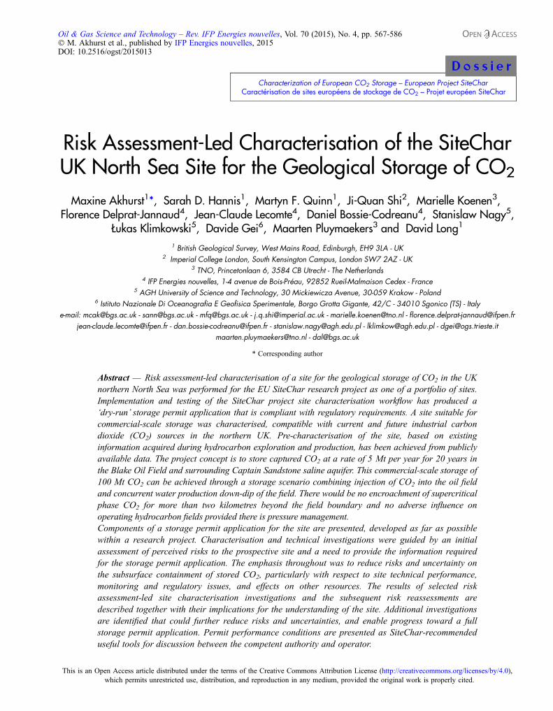
The site lies offshore in the UK sector of the North Seaapproximately 75 km north-east of the St Fergus gas termi-nal on the north-east coast of Scotland (Fig. 1). The projectconcept is for commercial-scale storage of CO2 sourcedfrom industrial plant along the eastern coast of Scotlandand transported offshore via existing oil and gas pipelinesfrom St Fergus. Opportunities for carbon capture and storageoffshore Scotland have been assessed and developed by pre-vious studies (SCCS, 2009, 2011). Output of CO2 fromexisting industrial sources has been quantified, the futureCO2 output forecast, storage sites assessed, and cost forpipeline and shipping for the transportation of CO2 esti-mated (SCCS, 2009).
The Captain Sandstone was amongst those saline aquifersshortlisted as prospective storage assets by Scottish Centrefor Carbon Storage (SCCS, 2009). It meets acceptable geolog-ical characteristics as indicated by Chadwick et al. (2008) andhas sufficient potential storage capacity. The CaptainSandstonehas an estimated staticCO2 storage capacity rangingfrom 36 Mt (applying a storage efficiency of 0.2%) to 363 Mt(applying a storage efficiency of 2%) (SCCS, 2009). Charac-terisation and calculation of storage capacity by dynamicmodeling of CO2 injection endorses a potential capacity ofmore than360Mt for theCaptain Sandstone saline aquiferwitha storage efficiency of more than 0.6% by Scottish CarbonCapture and Storage (SCCS, 2011).
The Captain Sandstone was selected for research assess-ment as an example of a commercial-scale CO2 storage assetfor Scotland following an examination of three sandstones.Each was appraised on its proximity to existing onshore CO2
sources, estimated storage capacity, access to existing oil andgas pipelines,whether known fromoil and gas exploration dataand having sufficient data accessible to a research project(SCCS, 2011). Selected 2D seismic survey and well data wereinterpreted to map and characterise the site and a basin-scalemodel was constructed and attributed with petrophysical
characteristics (SCCS, 2011). Dynamic simulation of CO2 cal-culated the potential storage capacity to be at least as much asthe previously estimated upper value and possibly muchgreater (Jin et al., 2012). Further assessment of the CaptainSandstone as a potential CO2 store was considered as justified(SCCS, 2011). The basin-scale model of Scottish CarbonCap-ture and Storage (SCCS, 2011) was also used for the SiteCharUK northern North Sea storage site (Fig. 1).
The SiteChar research benefited from publicly availableassessments of the Goldeneye Gas Field for CO2 storage(Shell, 2011a, b). The Goldeneye Field is also within theCaptain Sandstone and lies 30 kilometres to the east of theSiteChar UK site study area. During 2013 the CaptainSandstonewasproposedas the storage reservoir for twoprojectentrants to the UK CCS demonstrator competition, onepreferred and one reserve project (DECC, 2013). The site char-acterisation research presented here assesses a site that is inaddition to others proposed within the Captain Sandstone as aprospective multi-user storage asset.
2 SITECHAR UK NORTH SEA STORAGE SITE
2.1 Geological Setting
The SiteChar UK North Sea storage site is within the Cap-tain Sandstone Member of the Lower Cretaceous Wick
LegendCaptain Sandstone extentFaults
Depth to top Captain
Hydrocarbon fields (in Captain)Field type
Contour (m)500100015002000
OilGasCondensateHydrocarbon fields (non-Captain)SiteChar basin scale modelSiteChar detailed model
Kilometres
Halibut Horst
EAST SHETLAND PLATFORM
N
0 5 10 20
Figure 1
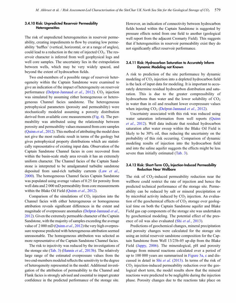
Map of the UK North Sea SiteChar storage site, structural con-tours (depth in metres True Vertical Depth Sub Sea) and faultsat top Captain Sandstone surface (after SCCS, 2011) showingthe SiteChar detailed model area and hydrocarbon fields hostedwithin the Captain Sandstone and older strata (Quinn et al.,2012). Contains public sector information licensed under theOpen Government Licence V.1.0. Field outlines and wells fromDECC 2011. Data available from: https://www.og.decc.gov.uk/pprs/full_production.htm.
M. Akhrust et al. / Risk Assessment-Led Characterisation of the SiteChar UK North Sea Site for the Geological Storage of CO2 569

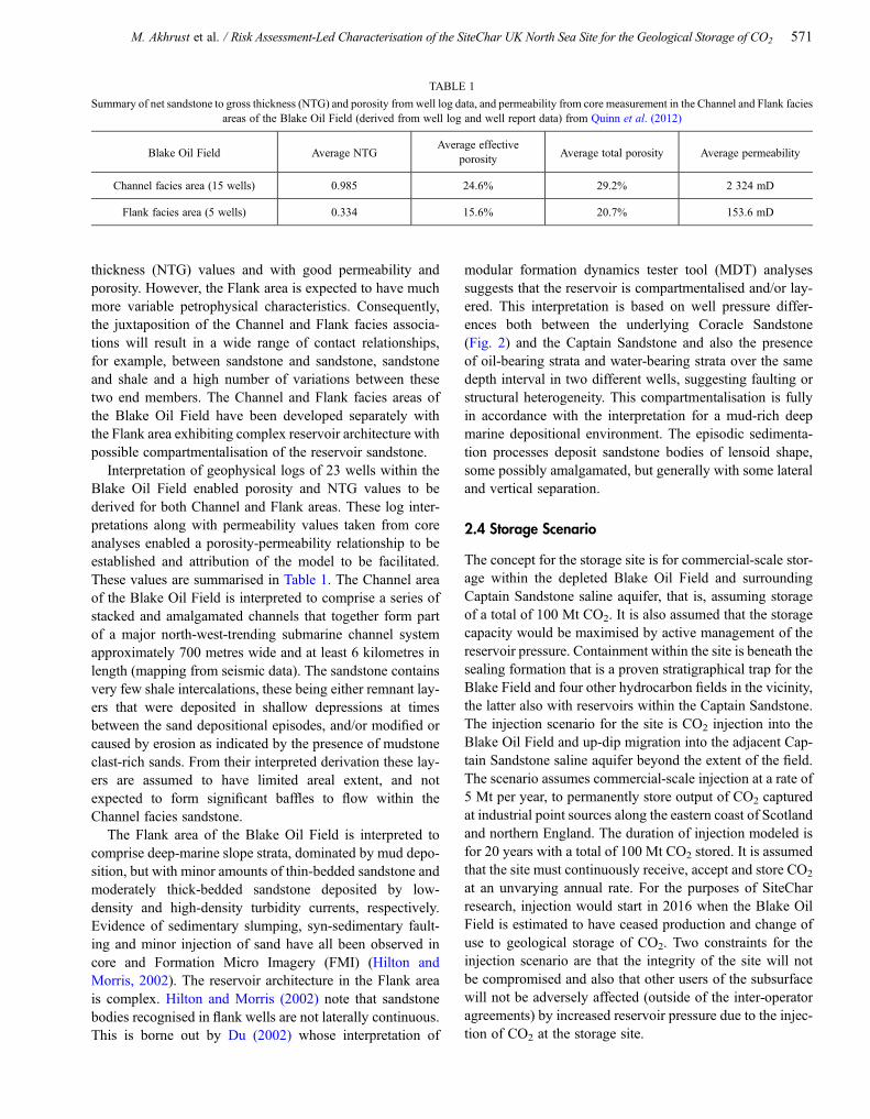
Sandstone Formation (Johnson and Lott, 1993) (Fig. 1, 2)(Quinn et al., 2012; Akhurst et al., 2014). The Captain Sand-stone member extends over an area of at least 3 400 km2 inthe Outer Moray Firth, offshore Scotland in the UK northernNorth Sea (Fig. 1). The sandstone was delineated by Johnsonand Lott (1993) and remapped by SCCS (2011). The CaptainSandstone is underlain and laterally equivalent to the argilla-ceous Valhall Formation, laterally equivalent to and overlainby the argillaceous Carrack Formation. Both of these forma-tions are in turn overlain by the Rodby Formation that alsohas sealing potential (Johnson and Lott, 1993) (Fig. 2).Rocks of the Upper Cretaceous Chalk Group may directlyoverlie the Captain Sandstone where the Carrack and Rodbyformations are absent (Fig. 2). The Palaeogene overburden
sequence comprises sandstone, mudstone, claystone, silt-stone and limestone of the Montrose and Moray groups(Fig. 2) (Knox and Holloway, 1992; Johnson and Lott,1993).
2.2 Hydrocarbon Field Site Selection
The Captain Sandstone contains four oil, gas and gas con-densate fields within the extent of the SiteChar study area(Fig. 1). The Blake Oil Field was selected because it meetsthe storage criteria of Chadwick et al. (2008), has sufficientestimated static storage capacity (28 Mt CO2) for a compo-nent of a commercial-scale storage site and data from thefield is publicly available. The Blake Oil Field has the largestpotential storage capacity of the three fields that lie at a depthgreater than 800 metres, to ensure CO2 injection in supercrit-ical phase. It lies at a minimum depth of 1 350 metres (truevertical sub-sea depth) in approximately 100 m water depth.The Blake Field has produced oil and gas since 2002 and isnow supported by water injection. There are publicly avail-able 3D seismic surveys across the Blake Field and datafrom 23 well penetrations within the field to constrain theseismic interpretation and attribute the site geological model.
The Blake Oil Field is located in the north-western end ofthe Captain Sandstone ‘pan-handle’ (Fig. 1). The SiteCharUK site detailed model area lies where the ‘pan-handle’begins to widen out into the main extent of the Captain Sand-stone (Fig. 1). Dynamic simulation of CO2 injection bySCCS (2011) has shown that predicted pressure increasedue to CO2 injection is greatest in the south-eastern part ofthe ‘pan handle’ where the width of the Captain Sandstoneis thought to be at its narrowest. Thus the Blake Oil Fieldis in an appropriate position, compared to fields furthersouth-east within the study area, to minimise the impact ofthe increase in pressure modeled by Jin et al. (2012).
2.3 Geology and Geological Models of the UKNorth Sea Storage Site
The Captain Sandstone was deposited in a deep-water sub-marine environment, sediment was derived from a sourceto the North and West and deposited by gravity-flow pro-cesses including high- and low-density turbidites, mudflows, debris flows, slides and slumps and settling ofhemi-pelagic sediment (Law et al., 2000).
Within the Blake Oil Field, the Captain Sandstone hasbeen divided into two distinct areas (Hilton, 1999) basedon facies associations that reflect deep marine depositionalprocesses: a ‘Channel’ facies area in the down-dip, south-western part of the field; a ‘Flank’ facies area up-dip to theNorth-East. The Channel facies area is likely to comprisesandstone with consistently high net sandstone to gross
Secondary seals
Secondarycontainment
Primaryseals
Primaryreservoir
*Base Captain Sandstone Member
KIMMERIDGE CLAY FM
VALHALLFORMATION
CARRACKFORMATION
RODBY FORMATION
HIDRAFORMATION
HERRINGFORMATION
MACKERELFORMATION
TORFORMATION
DO
RN
OC
HF
OR
MAT
ION
SE
LEF
OR
MAT
ION
LIS
TAF
OR
MAT
ION
EKOFISK FORMATION
MAUREENFORMATION
RECENT SEDIMENTS
PuntSandstone
Member
Rya
z-an
ian
Val
ang-
inia
nH
aute
r-iv
ian
Bar
rem
ian
Apt
ian
Alb
ian
UP
PE
R C
RE
TAC
EO
US
EA
RLY
PALE
OC
EN
EE
AR
LYE
OC
EN
ELA
TE
PA
LEO
CE
NE
CoracleSandstone
Member
CaptainSandstone
Member
Upper DornchSandstone
DornchMudstone
Lower DornchSandstone
Mey SandstoneMember
*Top Captain Sandstone Member
CH
ALK
GR
OU
PM
ON
TR
OS
E G
RO
UP
EA
RLY
PA
LAE
OG
EN
EC
RE
TAC
EO
US
LOW
ER
CR
ETA
CE
OU
S
MO
RAY
GR
OU
PC
RO
ME
R K
NO
LL G
RO
UP
WIC
K S
AN
DS
TON
E F
OR
MAT
ION
Sto
rage
site
Sto
rage
com
plex
Base Cretaceousseismic horizon
Base Chalkseismic horizon
Top Chalkseismichorizaon
Sea bedseismichorizon
Figure 2
Stratigraphy of the SiteChar UK North Sea storage site andstorage complex components (Quinn et al., 2012).
570 Oil & Gas Science and Technology – Rev. IFP Energies nouvelles, Vol. 70 (2015), No. 4
thickness (NTG) values and with good permeability andporosity. However, the Flank area is expected to have muchmore variable petrophysical characteristics. Consequently,the juxtaposition of the Channel and Flank facies associa-tions will result in a wide range of contact relationships,for example, between sandstone and sandstone, sandstoneand shale and a high number of variations between thesetwo end members. The Channel and Flank facies areas ofthe Blake Oil Field have been developed separately withthe Flank area exhibiting complex reservoir architecture withpossible compartmentalisation of the reservoir sandstone.
Interpretation of geophysical logs of 23 wells within theBlake Oil Field enabled porosity and NTG values to bederived for both Channel and Flank areas. These log inter-pretations along with permeability values taken from coreanalyses enabled a porosity-permeability relationship to beestablished and attribution of the model to be facilitated.These values are summarised in Table 1. The Channel areaof the Blake Oil Field is interpreted to comprise a series ofstacked and amalgamated channels that together form partof a major north-west-trending submarine channel systemapproximately 700 metres wide and at least 6 kilometres inlength (mapping from seismic data). The sandstone containsvery few shale intercalations, these being either remnant lay-ers that were deposited in shallow depressions at timesbetween the sand depositional episodes, and/or modified orcaused by erosion as indicated by the presence of mudstoneclast-rich sands. From their interpreted derivation these lay-ers are assumed to have limited areal extent, and notexpected to form significant baffles to flow within theChannel facies sandstone.
The Flank area of the Blake Oil Field is interpreted tocomprise deep-marine slope strata, dominated by mud depo-sition, but with minor amounts of thin-bedded sandstone andmoderately thick-bedded sandstone deposited by low-density and high-density turbidity currents, respectively.Evidence of sedimentary slumping, syn-sedimentary fault-ing and minor injection of sand have all been observed incore and Formation Micro Imagery (FMI) (Hilton andMorris, 2002). The reservoir architecture in the Flank areais complex. Hilton and Morris (2002) note that sandstonebodies recognised in flank wells are not laterally continuous.This is borne out by Du (2002) whose interpretation of
modular formation dynamics tester tool (MDT) analysessuggests that the reservoir is compartmentalised and/or lay-ered. This interpretation is based on well pressure differ-ences both between the underlying Coracle Sandstone(Fig. 2) and the Captain Sandstone and also the presenceof oil-bearing strata and water-bearing strata over the samedepth interval in two different wells, suggesting faulting orstructural heterogeneity. This compartmentalisation is fullyin accordance with the interpretation for a mud-rich deepmarine depositional environment. The episodic sedimenta-tion processes deposit sandstone bodies of lensoid shape,some possibly amalgamated, but generally with some lateraland vertical separation.
2.4 Storage Scenario
The concept for the storage site is for commercial-scale stor-age within the depleted Blake Oil Field and surroundingCaptain Sandstone saline aquifer, that is, assuming storageof a total of 100 Mt CO2. It is also assumed that the storagecapacity would be maximised by active management of thereservoir pressure. Containment within the site is beneath thesealing formation that is a proven stratigraphical trap for theBlake Field and four other hydrocarbon fields in the vicinity,the latter also with reservoirs within the Captain Sandstone.The injection scenario for the site is CO2 injection into theBlake Oil Field and up-dip migration into the adjacent Cap-tain Sandstone saline aquifer beyond the extent of the field.The scenario assumes commercial-scale injection at a rate of5 Mt per year, to permanently store output of CO2 capturedat industrial point sources along the eastern coast of Scotlandand northern England. The duration of injection modeled isfor 20 years with a total of 100 Mt CO2 stored. It is assumedthat the site must continuously receive, accept and store CO2
at an unvarying annual rate. For the purposes of SiteCharresearch, injection would start in 2016 when the Blake OilField is estimated to have ceased production and change ofuse to geological storage of CO2. Two constraints for theinjection scenario are that the integrity of the site will notbe compromised and also that other users of the subsurfacewill not be adversely affected (outside of the inter-operatoragreements) by increased reservoir pressure due to the injec-tion of CO2 at the storage site.
TABLE 1
Summary of net sandstone to gross thickness (NTG) and porosity from well log data, and permeability from core measurement in the Channel and Flank faciesareas of the Blake Oil Field (derived from well log and well report data) from Quinn et al. (2012)
Blake Oil Field Average NTGAverage effective
porosity Average total porosity Average permeability
Channel facies area (15 wells) 0.985 24.6% 29.2% 2 324 mD
Flank facies area (5 wells) 0.334 15.6% 20.7% 153.6 mD
M. Akhrust et al. / Risk Assessment-Led Characterisation of the SiteChar UK North Sea Site for the Geological Storage of CO2 571

3 RISK ASSESSMENT-LED SITE CHARACTERISATION
The objective of risk assessment-led site characterisation isto provide the information required by and in agreement withthe competent authority for award of a permit for geologicalstorage of CO2. A storage licence application is undertakenin two parts, an application for an exploration permit and anapplication for a storage permit. For the SiteChar UK NorthSea site, comprising in part a depleted hydrocarbon field, it isassumed that an exploration permit has previously beenawarded. For award of a storage permit the applicant(SiteChar research project) must demonstrate sufficientunderstanding of the site and proposed site operation tosecurely and permanently contain CO2. The resources for aresearch project are necessarily less than those that wouldbe expected for a real storage site permit application. Theobjectives of SiteChar research, to demonstrate geologicalcharacterisation and assess long-term storage complexbehaviour, are addressed by a ‘dry-run’ application for astorage permit. The storage permit application templatecompleted for the UK northern North Sea site was developedwithin SiteChar from stipulations and requirements in theEU Directive on the geological storage of CO2 regulationsand guidelines (EU, 2009, 2011).
Geological site characterisation activities were targeted toreduce the perceived risks, decrease uncertainty and increaseunderstanding of the storage site (Tab. 2). Geological (static)3D model construction and model attribution (Quinn et al.,2012) was followed by coupled dynamic simulation andgeomechanical modeling (Shi et al., 2013) and dynamicmodeling of CO2 injection (Delprat-Jannaud et al., 2012).Regional migration pathway analysis and wellbore integritymodeling was also undertaken (Delprat-Jannaud et al.,2012). Shallow geohazards were assessed and the geochem-ical response to CO2 injection was evaluated (Shi et al.,2013). Feasibility of monitoring was assessed by rock phys-ics studies and synthetic seismic modeling investigations(Hannis et al., 2013c).
3.1 Information Required from Site Characterisation
Information and components required for a storage permitapplication are determined by an assessment of risks to theCO2 storage site. Information required includes a descriptionof the storage project and a description of the storage site.Required storage permit components include details of mea-sures to prevent significant irregularities. Monitoring, cor-rective measures and post-closure plans are also required.The preventative measures component is based on a registerof risks and includes a plan of risk mitigation. The risk reg-ister is a key document as the starting point for site charac-terisation (Hannis et al., 2013b). Characterisation activitiesseek to reduce the perceived risks to subsurface containment
of CO2, and uncertainties due to lack of information, to alevel as low as reasonably possible.
3.2 Assessment of Risks to the CO2 Storage Site
At a very early stage in the site characterisation process anassessment of risks to the storage site was undertaken. It isthe first technical activity in the characterisation process asthe results determine all other site characterisation investiga-tions and is required by the EU CCS Directive (EU, 2009,2010). A risk register of 79 perceived risks to the prospectiveCO2 storage site were identified by SiteChar researchexperts. They estimated the probability of each risk occur-ring and the severity of impact if each risk did actually occur.This list was presented as a summary risk register (Nepveuet al., 2015). The initial assessment was qualitative ratherthan quantitative and focused on injection- and storage-related risks. Other risks relating to capture and transportof CO2, CO2 stream composition, offshore health and safetyoperations and financial risks, were considered outside thescope of the SiteChar research project. For a real CCS pro-ject, investigation of all risks would be required for a storagepermit application.
The risks were ranked according to the initial estimates ofprobability and severity and the ranked list used to guide sitecharacterisation, working toward reduction of risks to anacceptable ‘as low as reasonably possible’ level. Theresources of the research allowed investigation of selectedtechnical risks identified within the project. Those risks thatwere investigated followed the methodology as far as possi-ble. Where mitigation of a risk could not be achieved withinresearch project resources further risk- and uncertainty-reduction activities were suggested, such as laboratory anal-ysis, re-logging of wells, drilling new wells and baselinemonitoring surveys (Hannis et al., 2013a). For a storage per-mit application submitted by a prospective operator it isassumed that most of the risks would be reduced to anacceptable level by storage design; relatively few residualrisks would remain to be monitored (Hannis et al., 2013c).A list was prepared of those risks that were not mitigatedby the SiteChar project investigations. This list of residualrisks was used to guide the monitoring planning to ensurethat any remaining risks are monitored (Hannis et al.,2013c).
3.3 Risks Addressed
The technical investigations in SiteChar were targeted toinform reduction of risks to the subsurface containment ofstoredCO2,where site technical performancemight be less thanexpected, associated with monitoring and regulatory issues orhave a potentially adverse effect on other resources (Tab. 2).Investigation of risks to the prospective storage site is,
572 Oil & Gas Science and Technology – Rev. IFP Energies nouvelles, Vol. 70 (2015), No. 4

of necessity, confined to those risks associated with techni-cal matters as appropriate for a research project. Risksidentified by SiteChar experts associated with economic,
financial and environmental issues were not addressed.Technical investigations were directed to reduce risks andprovide information needed for a storage permit application.
TABLE 2
Risk assessment-led site characterisation investigations for selected risks identified for the SiteChar storage site in the UK North Sea discussed in this paper(for risk ratings see Tab. 3)
Risk type Risk description Risk reduction investigations SiteChar technical reports
Subsurface containment of storedCO2
Connection of storage site reservoirsandstone to an adjacent fault Geological site characterisation Quinn et al., 2012
Primary cap rock thin or absent Geological site characterisationand 3D modeling Quinn et al., 2012
Fluid migration pathway north-westwards out of the storage site
Dynamic modeling of CO2
injection, regional migrationanalysis
Delprat-Jannaud et al., 2012
Secondary reservoirs not present,laterally restricted or poor quality Geological site characterisation Quinn et al., 2012
Fracture pressure threshold of theprimary cap rock exceeded
Coupled dynamic simulation andgeomechanical modeling Shi et al., 2013
Cap rock fracture pressurethreshold lower than predicted
Dynamic modeling Delprat-Jannaud et al., 2012Cap rock capillary entry pressure
threshold exceeded
Injection-induced faults orfractures in cap rock Geomechanical modeling Shi et al., 2013
Fluid escape pathways upabandoned wells
Wellbore integrity modeling.Shallow geohazards assessment
Delprat-Jannaud et al., 2012Shi et al., 2013
Technical performance less thanexpected
Unpredicted reservoir permeabilityheterogeneities
Geological modeling. Dynamicmodeling of CO2 injection
Quinn et al., 2012Delprat-Jannaud et al., 2012
Hydrocarbon saturation toaccurately inform dynamic
modeling not known
Geological site characterisation Quinn et al., 2012
Short-term CO2 injection-inducedpermeability reduction near
wellbore
Geochemical evaluation Shi et al., 2013
Long-term CO2-inducedpermeability reduction in the
storage reservoir due togeochemical changes
Geochemical evaluation Shi et al., 2013
Monitoring or regulatory issues
Seismic monitoring ineffective dueto the presence of a strong reflector
in overlying strata
Synthetic seismic modeling Hannis et al., 2013c
Seismic monitoring ineffective atdetecting CO2
Rock physics studies Hannis et al., 2013c
Adverse effects on other resources
Interference with hydrocarbonfields from migration of CO2 orincreased pressure due to CO2
injection
Dynamic modeling of CO2 injection.Storage site performance forecast Delprat-Jannaud et al., 2012
Hannis et al., 2013a
Induced seismicity Geomechanical modeling Shi et al., 2013
M. Akhrust et al. / Risk Assessment-Led Characterisation of the SiteChar UK North Sea Site for the Geological Storage of CO2 573

During the course of the investigations additional datawere acquired or reviewed. The increased information, eitheron or relevant to the storage site, imparted a greater degree ofcertainty and informed the subsequent re-assessment ofrisks. During the progress of the investigations additionalrisks were identified, which is to be expected.
3.4 Risk Reduction Investigations
Site characterisation investigations were targeted to addressthe risks identified in the risk register and also to provide theinformation required for a storage permit application.Selected risk reduction investigations presented here aresummarised in Table 2. The list of all perceived risks tothe site and reassessed values of probability of occurrence,severity of impact and revised ranking of risks after comple-tion of the investigations are discussed by Hannis et al.(2013a). SiteChar investigations completed a single iterationof risk reduction activities but could not address all risks orcontinue with additional site characterisation to reduce risksto a level ‘as low as reasonably possible’. The full register ofrisks, explanation and designation of both initial and revisedvalues for probability, severity and ranking, preventative andcorrective measures, also further work that could be under-taken to more accurately define the risk are presented byHannis et al. (2013b).
The results of the risk reduction investigations for therisks presented in Table 2 and implications to the under-standing of each perceived risk are discussed in the follow-ing text sections.
3.4.1 Risk: Connection of the Storage Site Reservoir Sandstoneto an Adjacent Fault
The Captain Sandstone is inferred to extend to the adjacentWest Halibut Fault from interpretation of 2D seismic surveydata by SCCS (2011) (Fig. 1). The possibility of a flow path-way from the storage site reservoir sandstone to the faultbounding the Halibut Horst to the north presented a risk tothe subsurface containment of CO2.
3D seismic survey data was interpreted for the SiteChardetailed model area (Fig. 1). In the revised interpretationof more finely resolved data, the principal sandstone of thestorage site, the Captain Sandstone, is interpreted to pinchout in the hanging wall succession of the West Halibut Faultwithin the study area (Fig. 3) (Quinn et al., 2012). Dynamicmodeling of CO2 injection into the Captain SandstoneChannel facies (Tab. 1) was calculated for well locationseither within the extent of the Blake Oil Field or down-dipwithin the brine-saturated Captain Sandstone (Delprat-Jannaud et al., 2012). Twenty years of injection and thirtyyears after the end of injection were simulated. In all ofthe injection scenarios modeled, the CO2 (in supercritical
phase and dissolved in water) was predominantly retainedwithin the extent of the Channel facies. The injected CO2
is predicted to migrate very slowly beyond the Channel intothe Flank facies only after injection has ceased in the injec-tion scenario selected for the prospective storage site.
The likelihood of migration of CO2 to the West HalibutFault for the injection scenario proposed is therefore verylow. Reassessment of the initial risk from the results ofremapping of the Captain Sandstone and dynamic modelingof CO2 injection has reduced the probability of the riskoccurring and so also the risk rating (Tab. 3).
3.4.2 Risk: Primary Cap Rock Thin or Absent
The top of the Captain Sandstone is generally sealed byoverlying low permeability mudstone but in some placesthe mudstone is thin and it may be directly overlain by theunconformable Base Chalk surface. Some wells, e.g. Well13/22a-28 in the Captain Oil Field, prove Chalk restingdirectly on the Captain Sandstone. Chalk cap rock may notbe as efficient a seal as the mudstone.
The 3D seismic survey data interpreted for the SiteChardetailed study area does not resolve where the mudstonecap rock is absent but indicates where it is most likelyto be thin (less than 10 metres). Although geological mappingshows the Captain Sandstone is expected to be overlainby Lower Cretaceous mudstone across the extent of the stor-age complex, an area where the cap rock is interpreted tobe thin (<10 m) lies in the north-west part of theBlake Field within the Flank facies area (Quinn et al., 2012).
HALIBUT HORST
Storage ComplexPre-Cretaceous
Storage Site
Low
erC
reta
ceou
sU
pper
Cre
tace
ous
Cen
ozoi
c
SW NE
Figure 3
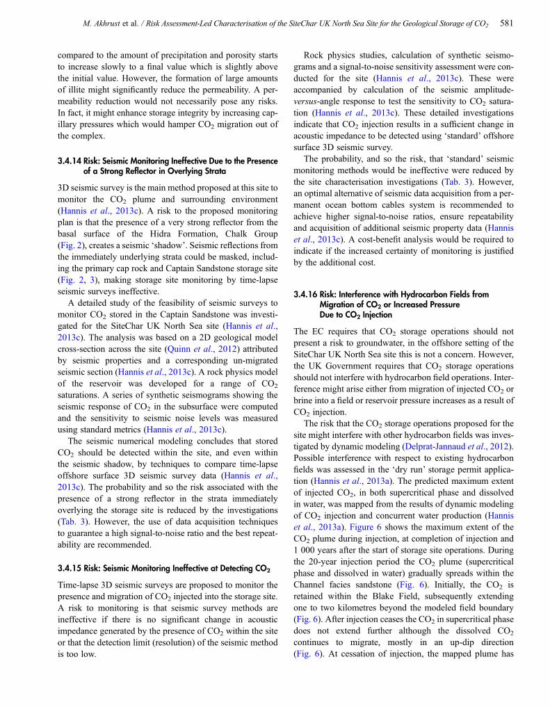
Diagrammatic geological cross-section across the SiteChar UKnorthern North Sea storage site, showing storage site boundary(red dashed line) and storage complex boundary (blue dashedline) from Quinn et al. (2012). Primary seal (cap rock), second-ary containment reservoir and secondary seal (cap rock) to thestorage complex are labelled.
574 Oil & Gas Science and Technology – Rev. IFP Energies nouvelles, Vol. 70 (2015), No. 4
However, dynamic modeling of the SiteChar storage site(Delprat-Jannaud et al., 2012) predicts the distribution ofthe plume of dissolved and supercritical phase CO2 toremain within the area where cap rock is mapped as being
continuous and having acceptable thickness (approximately40 metres thick).
The risk of leakage due to thin or absent primary cap rockis therefore thought to be low. Mapping of primary cap rock
TABLE 3
Risk ratings before and after the first iteration of risk reduction, based on site characterisation investigations (shown in Tab. 2) for the SiteChar UK North Seastorage site. Probability and severity ratings: 5 is high; 1 is low. NR, risk not reassessed
Risk type Risk descriptionInitial risk assessment Revised assessment
Probability Severity Risk rating Probability Severity Risk rating
Subsurfacecontainment ofstored CO2
Connection of storage site reservoirsandstone to an adjacent fault
3 3 9 1 3 3
Primary cap rock thin or absent 4 3 12 2 3 6
Fluid migration pathway north-westwards out of the storage site
2 3 6 1 3 3
Secondary reservoirs not present,laterally restricted or poor quality
2 2 4 1 2 2
Fracture pressure threshold of theprimary cap rock exceeded
2 4 8 1 4 4
Cap rock fracture pressure thresholdlower than predicted
3 3 9 1 1 3
Cap rock capillary entry pressurethreshold exceeded
3 3 9 3 1 3
Injection-induced faults or fracturesin cap rock
2 4 8 1 4 4
Fluid escape pathways upabandoned wells
4 4 16 2 2 4
Technicalperformance lessthan expected
Unpredicted reservoir permeabilityheterogeneities
4 4 8 2 2 4
Hydrocarbon saturation toaccurately inform dynamic
modeling not known4 3 12 2 2 4
Short-term CO2 injection-inducedpermeability reduction near
wellbore3 3 9 1 2 2
Long-term CO2 injection-inducedpermeability reduction in the storage
reservoir due to geochemicalchanges
3 3 9 1 2 2
Monitoring orregulatory issues
Seismic monitoring ineffective dueto the presence of a strong reflector
in overlying strata3 3 9 2 3 6
Seismic monitoring ineffective atdetecting CO2
3 3 9 2 3 6
Adverse effects onother resources
Interference with hydrocarbon fieldsfrom: migration of CO2,
increasedpressure due toCO2 injection
2 4 8 2 2 4
4 3 12 NR NR NR
Induced seismicity 2 3 6 1 3 3
M. Akhrust et al. / Risk Assessment-Led Characterisation of the SiteChar UK North Sea Site for the Geological Storage of CO2 575
and dynamic modeling of the selected injection scenario(Tab. 2) has reduced the probability of the risk occurringand so also the risk rating (Tab. 3).
3.4.3 Risk: Fluid Migration Pathway North-Westwardsout of the Storage Site
The Blake Oil Field forms a significant component to thestorage site and is a combined structural and stratigraphicaltrap. The field reservoir dips to the west and south providingstructural trapping to hydrocarbons filling the reservoir.The reservoir sandstone pinches out to the east providingstratigraphical trapping of hydrocarbons parallel to theHalibut Horst. However, the nature of the trap to hydrocar-bons in the Blake Oil Field along its northern boundary isnot clear as no structural closure to the field could be mappedwithin the limits of the seismic data available to the study(Quinn et al., 2012). There is a significant hydrocarbon dis-covery, the Tain discovery, immediately to the north of theBlake Oil Field beyond the SiteChar detailed area of study(Fig. 1). It is possible that hydrocarbons have migratedbeyond the northerly limits of the Blake Field, as definedby the Department of Energy and Climate Change (DECC),filling this small structure and presenting a risk to contain-ment of CO2 at the prospective storage site.
A regional migration analysis was conducted to identifypossible secondary containment and migration paths bymodeling substantial and excessive overfilling of the storagesite. Prediction of CO2 migration laterally within the CaptainSandstone (contained under the primary cap rock) if the site
is overfilled, indicates flow to the north-west in the directionof the Tain discovery (Delprat-Jannaud et al., 2012).However, the results of dynamic modeling of the choseninjection scenario suggest northward migration will notoccur if injection is into the Channel facies of the BlakeOil Field (Delprat-Jannaud et al., 2012). Although the Taindiscovery lies north-west of the storage site along a potentialregional migration pathway it is not thought to be connecteddirectly to the main Channel area of the Blake Field and mayhave more in common with the Flank area.
The risk to containment from fluid migration north-westwards from the storage site can therefore be consideredvery low. The probability of a fluid migration pathway to thenorth-west is reduced (Tab. 3) by conforming with the injec-tion scenario modeled and current understanding of poorconnectivity from the Channel to the Flank facies withinthe Captain Sandstone.
3.4.4 Risk: Secondary Reservoirs not Present, LaterallyRestricted or Poor Quality
In the unlikely event of migration of injected CO2 throughthe primary cap rock and out of the storage site, the CO2
would be expected to be contained within strata with avail-able pore space within the storage complex. Definition ofsecondary containment systems in the overall storage system,i.e. porous strata within the storage complex, is described asa component of the site (EU, 2009). A risk to the storage siteis that there are no suitable secondary reservoirs.
Review of published atlases for the stratigraphicalsequences in the area of the storage site (Knox andHolloway, 1992; Johnson and Lott, 1993) indicates stratapotentially suitable for both secondary containment and sec-ondary sealing for the storage of injected CO2. Migration ofinjected CO2 beyond the storage site may be containedwithin formations that overlie, underlie or are laterallyequivalent to the Captain Sandstone (Fig. 2, 3) (Quinnet al., 2012). The overlying Upper Cretaceous ChalkGroup succession has an average thickness of approximately460 metres over the detailed study area. The Chalk Groupcould provide additional containment for CO2 becausealthough the Chalk has low rock porosity and permeabilityit may have fracture porosity and permeability sufficient toprovide storage. The overlying Palaeogene successioncomprises sandstone, mudstone, claystone, siltstone andlimestone and has an average thickness of approximately1 000 metres over the SiteChar detailed study area. The sand-stone could provide very good secondary containment formigrating CO2 while the mudstone and claystone successionspresent in the Palaeogene Lista and Dornoch formations(Fig. 2) could provide a secondary cap rock to the storagecomplex (Fig. 3). Further site-specific investigation wouldimprove the characterisation of the secondary containment
0.05 0.10 0.15 0.20PORO
0.25 0.30
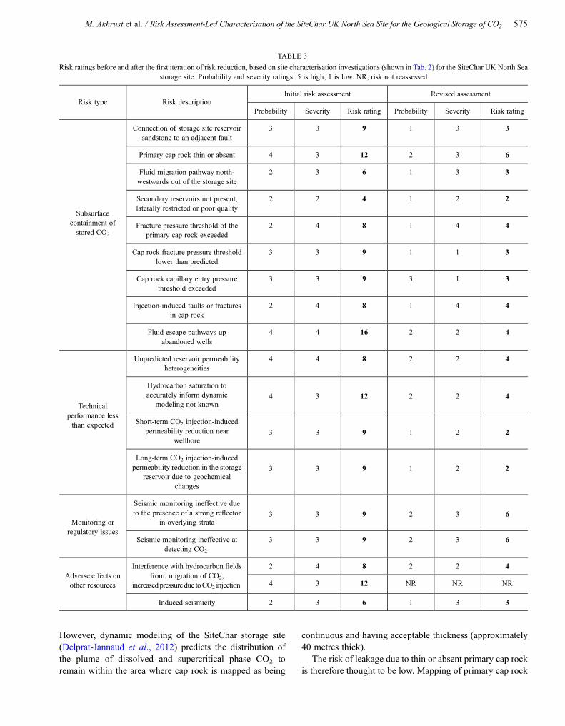
Figure 4
Modelled porosity within the SiteChar basin-scale study areaillustrating the distribution of Channel facies (values mostly0.25 and above) and Flank facies (values mostly 0.25 andbelow) within the Captain Sandstone, mapped from well data(Quinn et al., 2012).
576 Oil & Gas Science and Technology – Rev. IFP Energies nouvelles, Vol. 70 (2015), No. 4

reservoir and seal rockswith an estimateof possible volumes ofsecondary containment (Hannis et al., 2013a).
The risk associated with the possibility of inadequate sec-ondary storage strata is much reduced based on the pub-lished information by reducing the probability of the riskhappening (Tab. 3).
3.4.5 Risk: Fracture Pressure Threshold of the PrimaryCap Rock Exceeded
The cap rock fracture pressure threshold defines the pressure atwhich local fracturingof the cap rockmayoccur. If the pressurethreshold is exceeded the sealing properties of the cap rockcould be compromised, leading to leakage from the primarystorage reservoir. Avalue of around 75%of the lithostatic pres-sure is commonly assumed to approximate the fracture pres-sure threshold. Knowledge of the cap rock fracture pressureis vital to be able to derive realistic injection scenarios.
Coupled flow-geomechanical modeling of CO2 injectionand an evaluation of mechanical stability (Shi et al., 2013)accompanied by dynamic simulations to define an appropri-ate CO2 injection scenario (Delprat-Jannaud et al., 2012)were investigated for the storage site. The geomechanicalstability assessment used the pre-injection in situ stress stateinformation (one of the main sources of uncertainties in theassessment of geomechanical stability) from the nearbyGoldeneye Gas Field (Shell, 2011b). Based on these data,the overpressure value causing cap rock fracture has beenestimated as between 75 and 80 bar for the depth range ofthe storage site (1 600-1 700 m) by Shi et al. (2013).
Coupled flow-geomechanical modeling of CO2 injectioninto the Channel facies sandstone down-dip from the BlakeField at the commercial-scale rate without pressure manage-ment generated high overpressure values that would exceedthe cap rock fracture pressure threshold after 10 years (Shiet al., 2013). Even without pressure management no shearfailure is predicted after 5 years of injection at a rate of5 Mt CO2 per year into the Captain Sandstone saline aquiferbut continuation at this rate would exceed the fracture pres-sure threshold.
Different injection scenarios were simulated for the stor-age site all at a constant rate of 5 Mt CO2 per year. The max-imum reservoir pressure attained for CO2 injection into theBlake Oil Field with pressure management does not exceedthe cap rock fracture pressure (Delprat-Jannaud et al., 2012).Pressure management by concurrent fluid (water) productionfrom one well down-dip of the hydrocarbon field in theCaptain Sandstone saline aquifer was modeled. The pre-dicted maximum overpressure value for this scenario is26 bar after 20 years of CO2 injection. This value is substan-tially lower than the estimated threshold of 75-80 bar anddecreases to 8 bar overpressure after cessation of injection(Delprat-Jannaud et al., 2012). Further iterative dynamic
modeling using a range of injection rates and well positionswould allow the maximum rate and volume of injected CO2
without exceeding the pressure thresholds to be determined.Pressure management by implementing the chosen injectionand production scenario, although it may not be the opti-mum, would ensure the cap rock fracture pressure wouldnot be exceeded.
The probability of exceeding the cap rock fracture pres-sure has been reduced by determining the cap rock fracturepressure threshold and including pressure management inthe injection scenario (Tab. 3).
3.4.6 Risk: Cap Rock Fracture Pressure Threshold Lowerthan Predicted
The cap rock fracture pressure threshold estimated at75-80 bar overpressure at the storage site depth byShi et al. (2013) is very similar to the assumed valuesderived by calculating a proportion of the lithostatic orhydrostatic pressure. The maximum overpressure value pre-dicted for the chosen injection scenario of 26 bar overpres-sure is approximately one third of the estimated fracturepressure threshold. Therefore, subject to pressure manage-ment, the probability and risk that the threshold is exceededdue to a lower than predicted cap rock fracture pressure hasbeen reduced (Tab. 3) and the likelihood is very low.
3.4.7 Risk: Cap Rock Capillary Entry Pressure ThresholdExceeded
The cap rock capillary entry pressure threshold defines thepressure at which CO2 will start to slowly permeate throughthe capillaries of the sealing rock. It is lower than the fracturepressure, and leakage of CO2 through capillaries will beslow, at low volumes, and for long periods be containedwithin the cap rock itself.
The estimated cap rock capillary entry pressure is 36 bar(Delprat-Jannaud et al., 2012), based on the theoretical rela-tionship (Thomas et al., 1967) with and corresponding to anabsolute permeability of 10�5 mD. The theoretical entrypressure approximates the predicted maximum overpressureof 26 bar for the selected injection scenario. However, thesmall pressure difference between the two is not judged tobe a significant concern in terms of CO2 migration into thecap rock over the medium- to long-term due to the low per-meability of the cap rock. In the short term, the driving over-pressure will drop immediately once injection ceases andfurther dissipate over time. As the excess pressure will dropafter injection ceases, the risk is restricted to the period ofinjection and unlikely to be a source of leakage.
No further information was available to change theassessment of the probability that the cap rock entry pressurethreshold would be exceeded. However, the rates of leakage
M. Akhrust et al. / Risk Assessment-Led Characterisation of the SiteChar UK North Sea Site for the Geological Storage of CO2 577

from this mechanism are likely to be low and occur only dur-ing the decades of CO2 injection so the severity and overallrisk rating are reduced (Tab. 3).
3.4.8 Risk: Injection-Induced Faults or Fractures in Cap Rock
Fault structures have not been identified in the Captain Sand-stone reservoir and cap rock within the area of detailed studyfor the storage site from 3D seismic survey data (Quinnet al., 2012). A risk remains that there are minor fault struc-tures within the site that are not resolved in the seismic dataand the increased pressure associated with CO2 injectionmight induce fault reactivation to create flow pathwayswithin the storage site reservoir and through the primarycap rock.
The outcomes of the geomechanical modeling and failureanalysis by Shi et al. (2013) suggest that the likelihood offault reactivation within the Captain Sandstone is low pro-vided pressure is managed. An assessment of the likely pres-ence of fractures and their connectivity within the cap rockand overburden sequence was undertaken for the UKoffshore site by Shi et al. (2013). Fracture data for the caprock and overburden from well log and core data sourcesfrom within and in the vicinity of the storage site were usedto inform estimation of a percolating fracture network. Thecomputed percolation probability is strongly influenced bycap rock thickness, proportion of open (conducting) frac-tures and the number of fractures over a specified verticaldistance (line density). For the two scenarios with the lowestproportion of open fractures (0.1) and the thickest cap rock(227 m), the percolation probability is negligible.
Note here that natural gas and oil has been contained inthe Blake Field and other hydrocarbon fields over the geo-logical time scale which is evidence that should precludethe existence of a natural gas leakage pathway in the caprock. It thus can be argued that it is unlikely that a percolat-ing open fracture network exists in the cap rock.
The results of risk reduction investigations indicate theprobability of the presence of minor fractures has beenreduced and so also the risk that they might be reactivatedby CO2 injection (Tab. 3).
3.4.9 Risk: Fluid Escape Pathways Up Abandoned Wells
One of the major challenges associated with geological stor-age of CO2 is the prediction of performance of the confiningsystem and for the store to remain secure over long time-scales. Abandoned exploration and production wells act aspotential leakage pathways for CO2 stored in depletedhydrocarbon fields and adjacent saline aquifer strata. Hence,it is essential to investigate well integrity during the processof storage site evaluation.
Migration path analysis for the SiteChar UK North Seasite has identified possible leaking wells as the mostprobable pathway to the surface, transmitting CO2
directly to the atmosphere (Delprat-Jannaud et al.,2012). Fluid-escape pathways and CO2-induced fluidescape pathways up abandoned wells are rated as havingthe highest probability and severity and so ranked highestin the risk register (Hannis et al., 2013a, b). The potentialfor leakage of injected CO2 through the wellbore, and itssensitivity to cement bond condition and storage pressure,were investigated by numerical simulation of well integ-rity (Delprat-Jannaud et al., 2012). The analysis is basedon data from an appraisal well within the Channel faciesof the Blake Oil Field (BG Exploration & Production,1998). The scenarios simulated assume storage pressureand micro-annulus permeability values, 1 000 years ofelevated pressure and predict the mass of leaked CO2
at the top of the secondary containment strata. If reservoirpressures are maintained at 90% of the initial pressure noleakage of CO2 via the wellbore is predicted, even if apessimistic scenario for the micro-annulus permeabilityis assumed. At the initial reservoir pressure 1.3 tonnesof CO2 is predicted to leak to secondary storage viathe wellbore over a period of 1 000 years. Dynamic sim-ulation (Delprat-Jannaud et al., 2012) predicts up to26 bar overpressure within the Captain Sandstone reser-voir for the selected CO2 injection and water productionscenario. Well integrity modeling assuming CO2 storagepressure equal to 130% of the initial reservoir pressureand pessimistic micro-annulus permeability values pre-dicts up to 20 tonnes of CO2 leakage to the secondaryreservoir. All scenarios assume constant elevated pressureover a period of 1 000 years and the only way to reducethe pressure is via leakage through the wellbore. Thus theeffect of relaxation after stopping injection after 20 yearsis not incorporated in the calculations. Such conditionsmay therefore be considered as very pessimistic as inreality after stopping injection the reservoir pressure willdecrease with time and thus also the rate of CO2 leakage.
The risk for the scenario investigated was reduced by theSiteChar investigations (Tab. 3). Uncertainty in the numberof wells likely to fall within the predicted extent of theinjected CO2 plume (Fig. 6 in Sect. 3.4.16) and the massof CO2 leakage to the secondary reservoir was also reduced.Risk mitigation measures of additional well characterisation(Le Guen et al., 2008) are suggested and included as part ofthe preventative measures plan (Hannis et al., 2013c; Shiet al., 2013) and ‘dry-run’ storage permit application forthe site (Hannis et al., 2013a). Baseline observation andresurvey of the sea bed during injection over existing wellsites by sonar and echo sounder surveys (Shi et al., 2013)are a component of the monitoring plan (Hannis et al.,2013c).
578 Oil & Gas Science and Technology – Rev. IFP Energies nouvelles, Vol. 70 (2015), No. 4
3.4.10 Risk: Unpredicted Reservoir PermeabilityHeterogeneities
The risk of unpredicted heterogeneities in reservoir perme-ability, creating impediments to flow by creating low perme-ability ‘baffles’ (vertical, horizontal, or at a range of angles),could lead to a reduction in the rate of injected CO2. The res-ervoir character is inferred from well geophysical logs andwell core samples. The uncertainty lies in the extrapolationbetween wells, which may be very widely spaced, andbeyond the extent of hydrocarbon fields.
Two end-members of a possible range of reservoir heter-ogeneity within the Captain Sandstone were examined togive an indication of the impact of heterogeneity on reservoirperformance (Delprat-Jannaud et al., 2012). CO2 injectionwas simulated by assuming either homogeneous or hetero-geneous Channel facies sandstone. The heterogeneouspetrophysical parameters (porosity and permeability) werestochastically modeled assuming a porosity distributionderived from available core measurements (Fig. 4). The per-meability was attributed using the relationship betweenporosity and permeability valuesmeasured fromcore samples(Quinn et al., 2012). Thismethod of attributing themodel doesnot give the most realistic result in terms of the geology butgives petrophysical property distributions which are statisti-cally representative of existing input data. Observation of theCaptain Sandstone Channel facies in core recovered fromwithin the basin-scale study area reveals it has an extremelyuniform character. The Channel facies of the Captain Sand-stone is interpreted to be amalgamated turbidite sandstonedeposited from sand-rich turbidity currents (Law et al.,2000). The homogeneous Channel facies Captain Sandstonewas populated using average values of 0.25 for porosity fromwell data and 2 000 mD permeability from core measurementswithin the Blake Oil Field (Quinn et al., 2012).
Comparison of the simulations of CO2 injection into theChannel facies with either heterogeneous or homogeneousattribution reveals significant differences in the extent andmagnitude of overpressure anomalies (Delprat-Jannaud et al.,2012). Given the extremely permeable character of the CaptainSandstone, with themajority of samples exceeding the averagevalue of 2 000mD (Quinn et al., 2012) the very high overpres-sure response predicted with heterogeneous attribution seemedunreasonable. The homogeneous attribution was selected asmore representative of the Captain Sandstone Channel facies.
The risk to injectivity was reduced by the investigations ofthe storage site (Tab. 3) (Hannis et al., 2013b). The relativelylarge range of the estimated overpressure values from thetwo end-membersmodeled reflects the sensitivity to the degreeof heterogeneity represented in the model. Additional investi-gation of the attribution of permeability to the Channel andFlank facies is strongly advised and essential to impart greaterconfidence in the predicted performance of the storage site.
However, an indication of connectivity between hydrocarbonfields hosted within the Captain Sandstone is suggested bypressure effects noted from one field to another (geologicalwell report from the adjacent Cromarty Field). This suggeststhat if heterogeneities in reservoir permeability exist they donot significantly affect reservoir performance.
3.4.11 Risk: Hydrocarbon Saturation to Accurately InformDynamic Modeling not Known
A risk to prediction of the site performance by dynamicmodeling of CO2 injection into a depleted hydrocarbon fieldis the lack of input data for modeling. It is important to accu-rately determine residual hydrocarbon distribution and satu-ration. This is due to the greater compressibility ofhydrocarbons than water and the lower solubility of CO2
in water than in oil and resultant lower overpressure valueswhen injecting CO2 (Delprat-Jannaud et al., 2012).
Uncertainty associated with this risk was reduced usingwater saturation information from well reports (Quinnet al., 2012). Well data indicate that residual hydrocarbonsaturation after water sweep within the Blake Oil Field islikely to be 30% oil, thus reducing the uncertainty on theprobability of this risk occurring. Comparison of dynamicmodeling results of injection into the hydrocarbon fieldand into the saline aquifer suggests the effects might be lesssevere than initially estimated (Tab. 3).
3.4.12 Risk: Short-Term CO2 Injection-Induced PermeabilityReduction Near Wellbore
The risk of CO2-induced permeability reduction near thewellbore could restrict the rate of injection and hence thepredicted technical performance of the storage site. Perme-ability can be reduced by salt or mineral precipitation orby microbial activity induced by CO2 injection. An evalua-tion of the geochemical effects of CO2 storage over geolog-ical time on both the Captain Sandstone aquifer and BlakeField gas cap components of the storage site was undertakenby geochemical modeling. The potential effect of the pres-ence of oil was also evaluated (Shi et al., 2013).
Predictions of geochemical changes, mineral precipitationand porosity changes were calculated for the storage siteusing an initial reservoir sandstone composition for the Cap-tain Sandstone from Well 13/23b-05 up-dip from the BlakeField (Jappy, 2006). The mineralogical, pH and porositychange from mineral reactions calculated over a period ofup to 100 000 years are summarised in Figure 5a, c and dis-cussed in detail in Shi et al. (2013). In terms of the risk ofCO2 injection-induced permeability reduction over the geo-logical short term, the model results show that the mineralreactions were predicted to be negligible during the injectionphase. Porosity changes due to the reactions take place on
M. Akhrust et al. / Risk Assessment-Led Characterisation of the SiteChar UK North Sea Site for the Geological Storage of CO2 579
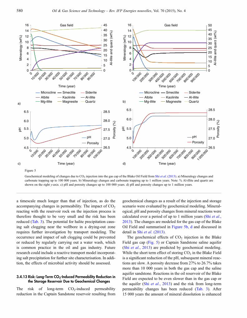
a timescale much longer than that of injection, as do theaccompanying changes in permeability. The impact of CO2
reacting with the reservoir rock on the injection process istherefore thought to be very small and the risk has beenreduced (Tab. 3). The potential for halite precipitation caus-ing salt clogging near the wellbore in a drying-out zonerequires further investigation by transport modeling. Theoccurrence and impact of salt clogging could be preventedor reduced by regularly carrying out a water wash, whichis common practice in the oil and gas industry. Futureresearch could include a reactive transport model incorporat-ing salt precipitation for further site characterisation. In addi-tion, the effects of microbial activity should be assessed.
3.4.13 Risk: Long-Term CO2-Induced Permeability Reduction inthe Storage Reservoir Due to Geochemical Changes
The risk of long-term CO2-induced permeabilityreduction in the Captain Sandstone reservoir resulting from
geochemical changes as a result of the injection and storagescenario were evaluated by geochemical modeling. Mineral-ogical, pH and porosity changes from mineral reactions werecalculated over a period of up to 1 million years (Shi et al.,2013). The changes are modeled for the gas cap of the BlakeOil Field and summarised in Figure 5b, d and discussed indetail in Shi et al. (2013).
The geochemical effects of CO2 injection in the BlakeField gas cap (Fig. 5) or Captain Sandstone saline aquifer(Shi et al., 2013) are predicted by geochemical modeling.While the short term effect of storing CO2 in the Blake Fieldis a significant reduction of the pH, subsequent mineral reac-tions are slow. A porosity decrease from 27% to 26.7% takesmore than 10 000 years in both the gas cap and the salineaquifer sandstone. Reactions in the oil reservoir of the BlakeField are expected to be even slower than in the gas cap orthe aquifer (Shi et al., 2013) and the risk from long-termpermeability changes has been reduced (Tab. 3). After15 000 years the amount of mineral dissolution is enhanced
16 Gas field
a) b)
c) d)
Time (year)
Time (year)
28.5 6.5
6.0
5.5
5.0
4.5
28.0
27.5
27.0 Por
osity
(%
)
pH
6.5
6.0
5.5
5.0
4.5
pH
26.5
Microcline Smectite Siderite
Albite Kaolinite Al-illiteMagnesite QuartzMg-illite
Min
eral
ogy
(wt%
)
Al-i
llite
and
qua
rz (
wt%
)14
12
10
8
6
4
2
0
10
15
20
25
30
35
40
45
5
00
1000
020
000
3000
040
000
5000
060
000
7000
080
000
9000
0
0
1000
020
000
3000
040
000
5000
060
000
7000
080
000
9000
010
0000
28.5
28.0
27.5
27.0 Por
osity
(%
)
26.5
Time (year)
10000
020
0000
30000
040
0000
50000
060
0000
70000
080
0000
90000
01 00
0000
Time (year)
Microcline Smectite Siderite
Albite Kaolinite Al-illiteMagnesite QuartzMg-illite
16 Gas field
Min
eral
ogy
(wt%
)
Al-i
llite
and
qua
rz (
wt%
)14
12
10
8
6
4
2
0
1015
2520
3035404550
50
0
0
10000
020
0000
30000
040
0000
50000
060
0000
70000
080
0000
90000
0
pH
Porosity
pH
Porosity
Figure 5
Geochemical modeling of changes due to CO2 injection into the gas cap of the Blake Oil Field from Shi et al. (2013). a) Mineralogy changes andcarbonate trapping up to 100 000 years. b) Mineralogy changes and carbonate trapping up to 1 million years. Note: % Al-illite and quartz areshown on the right y-axis. c) pH and porosity changes up to 100 000 years. d) pH and porosity changes up to 1 million years.
580 Oil & Gas Science and Technology – Rev. IFP Energies nouvelles, Vol. 70 (2015), No. 4
compared to the amount of precipitation and porosity startsto increase slowly to a final value which is slightly abovethe initial value. However, the formation of large amountsof illite might significantly reduce the permeability. A per-meability reduction would not necessarily pose any risks.In fact, it might enhance storage integrity by increasing cap-illary pressures which would hamper CO2 migration out ofthe complex.
3.4.14 Risk: Seismic Monitoring Ineffective Due to the Presenceof a Strong Reflector in Overlying Strata
3D seismic survey is the main method proposed at this site tomonitor the CO2 plume and surrounding environment(Hannis et al., 2013c). A risk to the proposed monitoringplan is that the presence of a very strong reflector from thebasal surface of the Hidra Formation, Chalk Group(Fig. 2), creates a seismic ‘shadow’. Seismic reflections fromthe immediately underlying strata could be masked, includ-ing the primary cap rock and Captain Sandstone storage site(Fig. 2, 3), making storage site monitoring by time-lapseseismic surveys ineffective.
A detailed study of the feasibility of seismic surveys tomonitor CO2 stored in the Captain Sandstone was investi-gated for the SiteChar UK North Sea site (Hannis et al.,2013c). The analysis was based on a 2D geological modelcross-section across the site (Quinn et al., 2012) attributedby seismic properties and a corresponding un-migratedseismic section (Hannis et al., 2013c). A rock physics modelof the reservoir was developed for a range of CO2
saturations. A series of synthetic seismograms showing theseismic response of CO2 in the subsurface were computedand the sensitivity to seismic noise levels was measuredusing standard metrics (Hannis et al., 2013c).
The seismic numerical modeling concludes that storedCO2 should be detected within the site, and even withinthe seismic shadow, by techniques to compare time-lapseoffshore surface 3D seismic survey data (Hannis et al.,2013c). The probability and so the risk associated with thepresence of a strong reflector in the strata immediatelyoverlying the storage site is reduced by the investigations(Tab. 3). However, the use of data acquisition techniquesto guarantee a high signal-to-noise ratio and the best repeat-ability are recommended.
3.4.15 Risk: Seismic Monitoring Ineffective at Detecting CO2
Time-lapse 3D seismic surveys are proposed to monitor thepresence and migration of CO2 injected into the storage site.A risk to monitoring is that seismic survey methods areineffective if there is no significant change in acousticimpedance generated by the presence of CO2 within the siteor that the detection limit (resolution) of the seismic methodis too low.
Rock physics studies, calculation of synthetic seismo-grams and a signal-to-noise sensitivity assessment were con-ducted for the site (Hannis et al., 2013c). These wereaccompanied by calculation of the seismic amplitude-versus-angle response to test the sensitivity to CO2 satura-tion (Hannis et al., 2013c). These detailed investigationsindicate that CO2 injection results in a sufficient change inacoustic impedance to be detected using ‘standard’ offshoresurface 3D seismic survey.
The probability, and so the risk, that ‘standard’ seismicmonitoring methods would be ineffective were reduced bythe site characterisation investigations (Tab. 3). However,an optimal alternative of seismic data acquisition from a per-manent ocean bottom cables system is recommended toachieve higher signal-to-noise ratios, ensure repeatabilityand acquisition of additional seismic property data (Hanniset al., 2013c). A cost-benefit analysis would be required toindicate if the increased certainty of monitoring is justifiedby the additional cost.
3.4.16 Risk: Interference with Hydrocarbon Fields fromMigration of CO2 or Increased PressureDue to CO2 Injection
The EC requires that CO2 storage operations should notpresent a risk to groundwater, in the offshore setting of theSiteChar UK North Sea site this is not a concern. However,the UK Government requires that CO2 storage operationsshould not interfere with hydrocarbon field operations. Inter-ference might arise either from migration of injected CO2 orbrine into a field or reservoir pressure increases as a result ofCO2 injection.
The risk that the CO2 storage operations proposed for thesite might interfere with other hydrocarbon fields was inves-tigated by dynamic modeling (Delprat-Jannaud et al., 2012).Possible interference with respect to existing hydrocarbonfields was assessed in the ‘dry run’ storage permit applica-tion (Hannis et al., 2013a). The predicted maximum extentof injected CO2, in both supercritical phase and dissolvedin water, was mapped from the results of dynamic modelingof CO2 injection and concurrent water production (Hanniset al., 2013a). Figure 6 shows the maximum extent of theCO2 plume during injection, at completion of injection and1 000 years after the start of storage site operations. Duringthe 20-year injection period the CO2 plume (supercriticalphase and dissolved in water) gradually spreads within theChannel facies sandstone (Fig. 6). Initially, the CO2 isretained within the Blake Field, subsequently extendingone to two kilometres beyond the modeled field boundary(Fig. 6). After injection ceases the CO2 in supercritical phasedoes not extend further although the dissolved CO2
continues to migrate, mostly in an up-dip direction(Fig. 6). At cessation of injection, the mapped plume has
M. Akhrust et al. / Risk Assessment-Led Characterisation of the SiteChar UK North Sea Site for the Geological Storage of CO2 581

a predicted area of 21 km2, extending to 23 km2 after a fur-ther 20 years which is the anticipated date of site closure(Hannis et al., 2013a). Details of the distribution of theCO2 in supercritical phase, dissolved CO2 and hydrocarbonphases are discussed by Hannis et al. (2013a).
The predicted increase in reservoir pressure within theBlake Oil Field and adjacent sandstone, greater than the ini-tial reservoir pressure of 161 bar, and hydrocarbon fieldswithin the Captain Sandstone is illustrated in Figure 7(Hannis et al., 2013a). The position of the CO2 injectionand water production wells is shown in Figure 6. Little pres-sure change is noted at the position of the Captain Oil Fieldfrom the modeling of storage site operations. There is aninitial pressure drop south-east of the site at the position ofthe Atlantic and Cromarty fields, due to water production.During CO2 injection, there is a progressive increase to amaximum overpressure value of 27 bar (Fig. 7). The over-pressure values drop immediately CO2 injection ceases.The investigations did not include modeling of hydrocarbonfluids other than in the Blake Field.
The risk of migration of the injected CO2 to other hydro-carbon fields in the vicinity of the storage site is reduced(Tab. 3) and negligible for the modeled CO2 injection andwater production (Fig. 6). There is little increase in reservoirpressure due to modeled storage operations predicted at theposition of the Captain Oil Field, the only operating fieldhosted within the Captain Sandstone in the vicinity of thesite (Fig. 7). The Atlantic and Cromarty fields have ceasedproduction, although the modeled pressure changes might
be beneficial to any future operations. The risk from interfer-ence with hydrocarbon fields due to increased reservoir pres-sure from CO2 injection was not reassessed (Tab. 3). Furthermodeling is required, incorporating fluid properties ofnearby fields, to quantify pressure changes from storage siteoperations and reassess the risk to nearby hydrocarbonfields.
3.4.17 Risk: Induced Seismicity
The possibility of increased seismicity associated with theoperation of a prospective storage site is identified as arequired component of the characterisation and assessmentof a prospective storage site (EU, 2009, 2011). Subsurfacepressure changes associated with CO2 injection may reacti-vate faults or generate minor fractures which may be evidentas increased measured seismicity.
The outcomes of the geomechanical modeling and failureanalysis for the SiteChar UK North Sea site suggest that theprobability of increased seismicity induced by CO2 injectionis low when the overpressure does not exceed the fracturepressure threshold (Shi et al., 2103). The scenario of CO2
injection with pressure management by concurrent waterproduction, which is the case for the chosen injection sce-nario, is proposed to ensure fracturing of reservoir or caprock should not occur. Given the low predicted magnitudeof overpressure in the Captain Sandstone (Fig. 7) relativeto the estimated cap rock fracture overpressure threshold of75-80 (Shi et al., 2013) there is a low probability of theoccurrence of this risk.
The site characterisation investigations have reduced theprobability and so the risk of induced seismicity due to stor-age site operations (Tab. 3). However, microseismic moni-toring is included as a regular monitoring component ofthe monitoring plan to assure that site integrity is maintainedor to identify if the operation is inducing adverse seismicevents.
4 RESULTS OF RISK ASSESSMENT-LED SITECHARACTERISATION
Risk assessment-led site characterisation focuses investiga-tions at a prospective site to provide information requiredfor a storage permit application. The outputs inform thedefinition of the site, determine storage site design andoperation or form the components of an application for aCO2 storage permit. An application for a storage permitsubmitted to the competent authority of a European mem-ber state should comply with the EU directive and guid-ance on the geological storage of carbon dioxide (EU,2009, 2010, 2011) and is reviewed by the EuropeanCommission.
LegendWell Integrity study 13/24a_06
Injection Well 13/24a_4
Water Producer 13/29b_9
Monitoring Well 13/29b_6
Other wells
SiteChar detailed model area
Storage Permit Area
Captain_ModelGrid_outline
Channel-Flank boundary
Simulation_Blake_field
Predicted_MaxPlume_5yrs
Predicted_MaxPlume_10yrs
Predicted_MaxPlume_20yrs
Predicted_MaxPlume_30yrs
Predicted_MaxPlume_40yrs
Predicted_MaxPlume_50yrs
Predicted_MaxPlume_1000yrs0 1.5 3
Kilometres
N
6
Flankfacies
ChannelfaciesFlank facies
Figure 6
Maximum predicted extent of the CO2 plume (supercriticalphase and dissolved in water) mapped during and after the pro-posed storage site operations, showing the Channel and Flankfacies Captain Sandstone, well positions and modeled extentof the Blake Oil Field from Hannis et al. (2013c).
582 Oil & Gas Science and Technology – Rev. IFP Energies nouvelles, Vol. 70 (2015), No. 4

4.1 Definition of the Storage Site and Storage Complex
The SiteChar UK North Sea storage site (Fig. 2, 3) is locatedprincipally in the Captain Sandstone Member of the LowerCretaceous Wick Sandstone Formation (Johnson and Lott,1993). Vertically, the storage site is defined as the entireWick Sandstone Formation because the Captain Sandstonemay be hydraulically connected to the underlying Coracleand Punt sandstone members (Fig. 2, 3) (Quinn et al.,2012; Akhurst et al., 2014).
The storage complex is a defined volume that extendsbeyond the storage site. The SiteChar UK North Sea storagecomplex extends vertically to include the rocks directlyabove the storage site up to the sea bed (Fig. 3). The storagecomplex includes the primary cap rock to the storage site,comprising mudstone of the Valhall, Carrack and Rodby for-mations (Johnson and Lott, 1993) (Fig. 2). Rocks of theoverlying Chalk Group may also act as seal if they are of suf-ficiently low permeability (Fig. 2). Secondary reservoirs forCO2 are strata overlying and laterally continuous with thestorage site that may be hydraulically connected. Theseinclude any rocks with available pore volume that overliethe primary cap rock, for example rocks of the Chalk Groupand sandstones in the Lista Formation of the Montrose
Group (Knox and Holloway, 1992; Johnson and Lott,1993) (Fig. 2). Secondary seal rocks (cap rocks to the sec-ondary reservoirs) are anticipated to be primarily non-calcareous mudstone of the Lista Formation of the MontroseGroup and the mud-prone Moray Group (Fig. 2) (Quinnet al., 2012; Akhurst et al., 2014).
Laterally, the storage complex boundaries enclose adefined volume beyond the storage site. The lateral extentof the storage complex is the same as the storage permit areashown in Figure 6 (Hannis et al., 2013a). The storage com-plex area encloses the maximum predicted plume extent(Fig. 6) and extends one kilometre beyond to reflect thesingle investigation of sensitivities conducted during sitecharacterisation and recommendation for additional investi-gations (Hannis et al., 2013a). The complex includes thelowest closing structural contour enclosing both the injectionand water production well of the Captain Sandstone uppersurface. It also encompasses the area up-dip (North-East)of the predicted plume extent to reflect the lack of knowl-edge of the property variations between the Channel andFlank facies sandstones in this direction (Delprat-Jannaudet al., 2012). The overall recti-linear shape of the storagecomplex is defined by the existing hydrocarbon licenceblocks for which agreement with existing licence holders
0 years
LegendStorage Permit Area
Simulation_Blake_field
Operation wells
1 year
10 years 20 years
5 years
N
N
N
N
Kilometres0 5 10 20
Kilometres0 5 10 20
Kilometres
N
0 5 10 20
Kilometres
Overpressure(pressure
above initial)in bar
-12-10
0
10
20
27
0 5 10 20
Figure 7
Reservoir pressure change in the ‘pan handle’ of the Captain Sandstone study area predicted from dynamic modeling of the proposed 20-yearperiod of CO2 injection and water production (Delprat-Jannaud et al., 2012) showing the position of hydrocarbon fields hosted within the CaptainSandstone from Hannis et al. (2013a). Inset shows the position of the Blake Field (red outline) and other hydrocarbon fields (black outlines), seealso Figure 1.
M. Akhrust et al. / Risk Assessment-Led Characterisation of the SiteChar UK North Sea Site for the Geological Storage of CO2 583
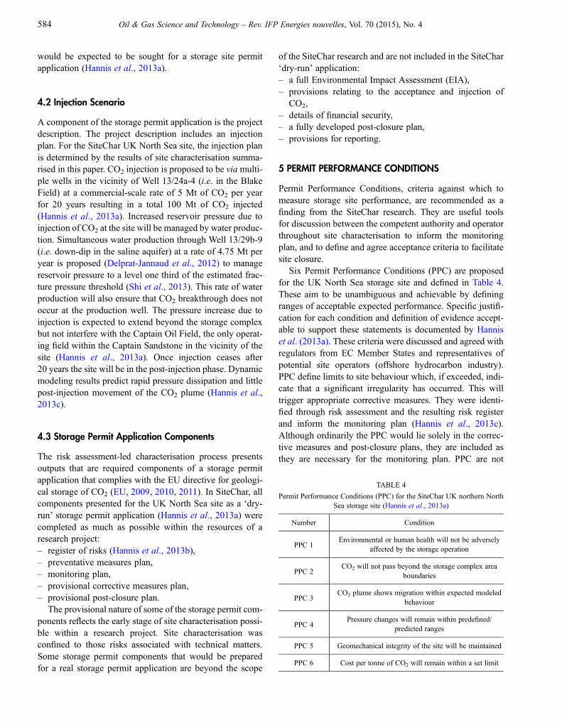
would be expected to be sought for a storage site permitapplication (Hannis et al., 2013a).
4.2 Injection Scenario
A component of the storage permit application is the projectdescription. The project description includes an injectionplan. For the SiteChar UK North Sea site, the injection planis determined by the results of site characterisation summa-rised in this paper. CO2 injection is proposed to be viamulti-ple wells in the vicinity of Well 13/24a-4 (i.e. in the BlakeField) at a commercial-scale rate of 5 Mt of CO2 per yearfor 20 years resulting in a total 100 Mt of CO2 injected(Hannis et al., 2013a). Increased reservoir pressure due toinjection of CO2 at the site will be managed by water produc-tion. Simultaneous water production through Well 13/29b-9(i.e. down-dip in the saline aquifer) at a rate of 4.75 Mt peryear is proposed (Delprat-Jannaud et al., 2012) to managereservoir pressure to a level one third of the estimated frac-ture pressure threshold (Shi et al., 2013). This rate of waterproduction will also ensure that CO2 breakthrough does notoccur at the production well. The pressure increase due toinjection is expected to extend beyond the storage complexbut not interfere with the Captain Oil Field, the only operat-ing field within the Captain Sandstone in the vicinity of thesite (Hannis et al., 2013a). Once injection ceases after20 years the site will be in the post-injection phase. Dynamicmodeling results predict rapid pressure dissipation and littlepost-injection movement of the CO2 plume (Hannis et al.,2013c).
4.3 Storage Permit Application Components
The risk assessment-led characterisation process presentsoutputs that are required components of a storage permitapplication that complies with the EU directive for geologi-cal storage of CO2 (EU, 2009, 2010, 2011). In SiteChar, allcomponents presented for the UK North Sea site as a ‘dry-run’ storage permit application (Hannis et al., 2013a) werecompleted as much as possible within the resources of aresearch project:– register of risks (Hannis et al., 2013b),– preventative measures plan,– monitoring plan,– provisional corrective measures plan,– provisional post-closure plan.
The provisional nature of some of the storage permit com-ponents reflects the early stage of site characterisation possi-ble within a research project. Site characterisation wasconfined to those risks associated with technical matters.Some storage permit components that would be preparedfor a real storage permit application are beyond the scope
of the SiteChar research and are not included in the SiteChar‘dry-run’ application:– a full Environmental Impact Assessment (EIA),– provisions relating to the acceptance and injection of
CO2,– details of financial security,– a fully developed post-closure plan,– provisions for reporting.
5 PERMIT PERFORMANCE CONDITIONS
Permit Performance Conditions, criteria against which tomeasure storage site performance, are recommended as afinding from the SiteChar research. They are useful toolsfor discussion between the competent authority and operatorthroughout site characterisation to inform the monitoringplan, and to define and agree acceptance criteria to facilitatesite closure.
Six Permit Performance Conditions (PPC) are proposedfor the UK North Sea storage site and defined in Table 4.These aim to be unambiguous and achievable by definingranges of acceptable expected performance. Specific justifi-cation for each condition and definition of evidence accept-able to support these statements is documented by Hanniset al. (2013a). These criteria were discussed and agreed withregulators from EC Member States and representatives ofpotential site operators (offshore hydrocarbon industry).PPC define limits to site behaviour which, if exceeded, indi-cate that a significant irregularity has occurred. This willtrigger appropriate corrective measures. They were identi-fied through risk assessment and the resulting risk registerand inform the monitoring plan (Hannis et al., 2013c).Although ordinarily the PPC would lie solely in the correc-tive measures and post-closure plans, they are included asthey are necessary for the monitoring plan. PPC are not
TABLE 4
Permit Performance Conditions (PPC) for the SiteChar UK northern NorthSea storage site (Hannis et al., 2013a)
Number Condition
PPC 1Environmental or human health will not be adversely
affected by the storage operation
PPC 2CO2 will not pass beyond the storage complex area
boundaries
PPC 3CO2 plume shows migration within expected modeled
behaviour
PPC 4Pressure changes will remain within predefined/
predicted ranges
PPC 5 Geomechanical integrity of the site will be maintained
PPC 6 Cost per tonne of CO2 will remain within a set limit
584 Oil & Gas Science and Technology – Rev. IFP Energies nouvelles, Vol. 70 (2015), No. 4
explicitly required by the EU storage directive (EU, 2009)but are SiteChar-recommended useful tools for discussionbetween the competent authority and operator and a wayto define and agree acceptance criteria. This will ultimatelyalso facilitate site hand-over and closure at the end of theterm, if a storage permit is awarded.
CONCLUSIONS
Risk assessment-led site characterisation investigations tar-geted to meet the requirements of a storage permit applicationhave been implemented for a prospective storage site in theUKnorthern North Sea. The process of risk assessment-led sitecharacterisation has been followed, as specified in the ECdirective for the geological storage of CO2, to provide therequired components as a ‘dry-run’ storage permit application.Pre-characterisation of a storage site comprising a hydrocarbonfield and adjacent saline aquifer sandstone has been achievedbased on publicly available data acquired during hydrocarbonexploration and production. Access to data available to thehydrocarbon field operator would greatly reduce uncertaintiesassociated with site characterisation assessment.
Commercial-scale storage of 100 Mt CO2, injected at anannual rate of 5 Mt for 20 years, can be achieved withoutthreat to the integrity of the site by pressure management.The pressure is managed by injection of CO2 into the BlakeOil Field and concurrent water production from the CaptainSandstone saline aquifer down-dip from the field. Optimisa-tion of the CO2 injection and water production well positionsand the CO2 injection rate is recommended to maximisestorage capacity and minimise the cost of the storageoperation.
Site characterisation and a first iteration of risk reductionhave been conducted for the mostly highly rated technicalrisks. Site characterisation has reduced most of the risksinvestigated. However, further iterations of risk assessment-led site characterisation are required to reduce the risks to ‘aslow as reasonably possible’ and to be sufficient to warrant sub-mission of a storage permit application to the competentauthorities.
Risk reduction and mitigation measures are proposed tofurther reduce risks, decrease uncertainties, and increasecertainty in the prospective storage site. Abandoned wellsremain the most likely fluid escape pathways. However, themass of CO2 migrating within the storage complex via aleaking wellbore is modeled as a maximum of 20 tonnes per100million tonnes injected, despite assuming very pessimisticconditions.
The impact of CO2 reacting with the reservoir rock duringthe period of injection is predicted to be negligible by geo-chemical modeling with a modest net increase in porosity overa periodofonemillion years.Thepotential for salt precipitationand the effects of microbial activity should also be assessed.
Rock physics studies and seismic modeling indicate theinjected CO2 should be detectable using time-lapse surface3D seismic survey data acquired using standard methods.However, a cost-benefit analysis for acquisition of sea bottomseismic data is recommended. Dynamic simulation of theBlake Oil Field and adjacent Captain Sandstone indicates thatafter 1 000 years the injected supercritical phase CO2would beretainedwithin two kilometres beyond the field boundary. Pro-vided the pressure of injection within the sandstone is main-tained at acceptable levels there would be no adverseinfluence on operating hydrocarbon fields from the pressureof injection. The pressure changes on adjacent non-producinghydrocarbonfields are predicted for the proposed injection sce-nario and geology modeled.
The risk assessment-led characterisation process presentsoutputs that are required components of a storage permit appli-cation that complieswith the EUdirective for geological storageof CO2 (EU, 2009, 2010, 2011). A prospective storage site, stor-age complex and storage scenario have been defined and storagepermit components were presented, as much as possible withinthe resources of a research project. In addition, PPC, criteriaagainst which to measure the site performance, are recom-mended as useful tools for discussion between the competentauthority and operator throughout the site characterisation pro-cess to inform the monitoring plan, define and agree acceptancecriteria to facilitate site closure.
ACKNOWLEDGMENTS
The research leading to these results has received funding fromthe European Union Seventh Framework Programme (FP7/2007-2013) under grant agreementNo. 256705 aswell as fromEnel, Statoil, Vattenfall, Véolia Environnement, and the Scot-tish Government. The support and contribution of the ScottishGovernment in the conduct of the SiteChar research and fund-ing of the underpinning, preceding Scottish CCS studies bySCCS is gratefully acknowledged. Two anonymous reviewersare thanked for their constructive reviews which greatlyimproved an earlier version of this paper.
REFERENCES
AkhurstM.C., QuinnM.Q.,Delprat-Jannaud F., Bossie-CodreanuD.,Hannis S.D., Lecomte J.-C., McCormac M., Frykman P. (2014) Riskassessment-led pre-characterisation of a site for commercial-scalestorage of CO2, EAGE CO2 Geological Storage Workshop,Demonstrating storage integrity and building confidence in CCS,Stavanger, Norway, April.
Bentham M., Mallows T., Lowndes J., Green A. (2014) CO2 Stor-age Evaluation Database (CO2 Stored), the UK’s online storagedatabase, Energy Procedia 63, 5103-5113.
BG Exploration & Production (1998) Well 13/24a-6 GeologicalReport, June.
M. Akhrust et al. / Risk Assessment-Led Characterisation of the SiteChar UK North Sea Site for the Geological Storage of CO2 585

Chadwick R.A., Arts R., Bernstone C., May F., Thibeau S.,Zweigel P. (2008) Best practice for the storage of CO2 in salineaquifers, British Geological Survey Occasional PublicationNo. 14, Keyworth, Nottingham.DECC (2013) Preferred bidders announced in UK’s £1bn CCS Com-petition. Press release 13/028, 20March,UKDepartment of Energy&ClimateChange,Available at: https://www.gov.uk/government/news/preferred-bidders-announced-in-uk-s-1bn-ccs-competition.
Delprat-Jannaud F., Pearce J., Akhurst M., Nielsen C., Neele F.,Lothe A., Volpi V., Brunsting S., Vincké O. (2015) SiteChar-Methodology for a fit-for-purpose assessment of CO2 storagesites in Europe, Oil and Gas Science and Technology 70, 4,531-554.Delprat-Jannaud F., Maurand N., Roggero F., Bossie-Codreanu D.,Pluymaekers M., Nagy S., Klimkowski L., Akhurst M.C., Kirby G.A. (2012) Storage design, UK site. SiteChar Characterisation ofEuropean CO2 storage Deliverable No. D3.2, Available at: http://www.sitechar-CO2.eu/.DTI (2006) Industrial carbon dioxide emission and carbon dioxidestorage potential in the UK, Report number COAL R308 DTI/PubURN 06/2027, UK Government Department of Trade and Industry.Du E.K. (2002) Blake Flank Well 13/24a- 8, Test Analysis Report,BG Group, Petroleum Engineering.EU (2009) Storage Directive 2009/31/EC, Available at: http://eur-lex.europa.eu/LexUriServ/LexUriServ.do?uri=OJ:L:2009:140:0114:0135:EN:PDF.EU (2010) Implementation of Directive 2009/31/EC on the geolog-ical storage of carbon dioxide – Guidance Document 1 – CO2 stor-age life cycle risk management framework.EU (2011) Implementation of Directive 2009/31/EC on the geolog-ical storage of carbon dioxide – Guidance Document 2 – Character-isation of the storage complex, CO2 stream composition,monitoring and corrective measures.Hannis S.D., Kirby G.A., Akhurst M.C. (2013a) Dry-run licenceapplication, UK site SiteChar Characterisation of European CO2 stor-age Deliverable No. D3.6, Available at: http://www.sitechar-CO2.eu/.Hannis S.D., Kirby G.A., Akhurst M.C. (2013b) Risk register forUK site, SiteChar Characterisation of European CO2 storage Deliv-erable No. D3.7, Available at: http://www.sitechar-CO2.eu/.Hannis S.D., Kirby G.A., Gei D., Picotti S., Bohm G., CarcioneJ.M., Rossi G., Arts R.J. (2013c) Monitoring Plan, UK site Site-Char Characterisation of European CO2 storage Deliverable No.D3.4, Available at: http://www.sitechar-CO2.eu/.Hilton V.C. (1999) Structural and sedimentological interpretation ofSTAR image data, core sedimentology and petrography Report forBG Exploration and Production, Blake Field, Well 13/24a- 6, BakerAtlas GEOScience.Hilton V.C., Morris S. (2002) An integrated interpretation of coreand borehole image data. Report for BG Group, Blake Flank, Wells13/24a-8, 8z & 8y, Baker Atlas GEOScience.Jappy I. (2006) Advance rock properties study for Talisman energy(UK) limited; well: 13/23b-5, Petroleum Services Division, CoreLaboratories (UK) Limited, Advanced Technology Centre.Jin M., Mackay E., Quinn M.F., Hitchen K., Akhurst M.C. (2012)Evaluation of the CO2 Storage Capacity of the Captain SandstoneFormation, SPE 154539, Presented at EAGE /SPE Europec Confer-ence and Exhibition, Copenhagen, Denmark.
Johnson H., Lott G.K. (1993) 2. Cretaceous of the Central andNorthern North Sea, in Lithostratigraphic nomenclature of theUK North Sea, Knox R.W.O’B., Cordey W.G. (eds), British Geo-logical Survey, Nottingham.
Knox R.W.O’B., Holloway S. (1992) 1. Palaeogene of the Centraland Northern North Sea, in Lithostratigraphic nomenclature of theUK North Sea, Knox R.W.O’B., Cordey W.G. (eds), British Geo-logical Survey, Nottingham.
Law A., Raymond R., White G., Atkinson A., Clifton M., AthertonT., Dawes I., Robertson E., Melvin A., Brayley S. (2000) The Kop-ervik fairway, Moray Firth, UK, Petroleum Geoscience 6, 265-274.
Le Guen Y., Le Gouevec J., Chammas R., Gerard B., Poupard O.(2008) CO2 Storage - Managing the Risk Associated with WellLeakage over Long Timescales, Society of Petroleum EngineersAsia Pacific Oil & Gas Conference and Exhibition, Perth,Australia, 20-22 Oct.
Nepveu M., Neele F., Delprat-Jannaud F., Akhurst M., Vincké O.,Volpi V., Lothe A., Brunsting S., Pearce J., Battani A., Baroni A.,Garcia B., Hofstee C., Wollenweber J. (2015) CO2 storage feasibil-ity: a workflow for site characterization, Oil and Gas Science andTechnology 70, 4, 555-566.
Quinn M.F., Akhurst M.C., Frykman P., Hannis S.D., Hovikoski J.,Kearsey T., Lecomte J.-C., McCormac M. (2012) Geological reportof the integrated Blake Oil Field and Captain Sandstone aquifer,UK multi-store site, SiteChar. SiteChar Report D3.1, http://www.sitechar-CO2.eu/.
ROAD (2013) The Rotterdam Capture and Storage DemonstrationProject, http://road2020.nl/en/.
SCCS (2009) Opportunities for CO2 Storage around Scotland —an integrated strategic research study, 56 pp., Available at: http://www.sccs.org.uk/images/expertise/reports/opportunities-for-co2/CO2-JointStudy-Full.pdf.
SCCS (2011) Progressing Scotland’s CO2 Storage opportunities, 60pp., Available at: http://www.sccs.org.uk/images/expertise/reports/progressing-scotlands-co2/ProgressingScotlandCO2Opps.pdf.
Shell (2011a) StaticModel FieldReport (UKCCS -KT- S7.21 - Shell –002), ScottishPower CCS Consortium, UK Carbon Capture andStorage Demonstration Competition, Available at: http://webarchive.nationalarchives.gov.uk/20121217150421/http://decc.gov.uk/assets/decc/11/ccs/sp-chapter3/ukccs-kt-s7.21-shell-002-smfr.pdf.
Shell (2011b) Geomechanics Summary Report (UKCCS -KT- S7.19 -Shell – 004), ScottishPowerCCSConsortium,UKCarbonCapture andStorage Demonstration Competition, Available at: http://webarchive.nationalarchives.gov.uk/20121217150421/http://decc.gov.uk/assets/decc/11/ccs/sp-chapter3/ukccs-kt-s7.19-shell-004-gsr.pdf.
Shi J.-Q., Govindon R., Syed A., Tambach T., Koenen M., Neele F.,Wildenborg A.F.B., Long D. (2013) Risk assessment, UK Site,SiteChar Characterisation of European CO2 storage DeliverableNo. D3.3, Available at: http://www.sitechar-CO2.eu/.
ThomasL.K.,KatzD.L, TekM.R. (1967) Threshold Pressure Phenom-ena in Porous Media, SPE 1816, 42nd Annual Fall Meeting, Oct.
Manuscript submitted in September 2014
Manuscript accepted in April 2015
Published online in August 2015
Cite this article as: M. Akhurst, S.D. Hannis, M.F. Quinn, J.-Q. Shi, M. Koenen, F. Delprat-Jannaud, J.-C. Lecomte,D. Bossie-Codreanu, S. Nagy, Ł. Klimkowski, D. Gei, M. Pluymaekers and D. Long (2015). Risk Assessment-Led Characterisationof the SiteChar UK North Sea Site for the Geological Storage of CO2, Oil Gas Sci. Technol 70, 4, 567-586.
586 Oil & Gas Science and Technology – Rev. IFP Energies nouvelles, Vol. 70 (2015), No. 4