risk analysis of forward extrusion process of hollow · pdf filejournal for technology of...
TRANSCRIPT
Journal for Technology of Plasticity, Vol. 32 (2007), Number 1-2
RISK ANALYSIS OF FORWARD EXTRUSION PROCESS OF HOLLOW ELEMENTS
Ranđelović Saša, Mladenović Srđan University of Niš, Faculty of Mechanical Engineering, Serbia
ABSTRACT
In order to develop a modern and efficient technological process it is necessary to acquire data concerning numerical evaluation and analysis of feed back information. In this way adaptive dynamic system can be created, both for the production process as well as for the process of design and development. Such a system would indicate possible errors and defectiveness which can occur in the processes of new product development. The current paper elaborates the process of forward extrusion from the risks point of view, using Failure Mode Effects Analysis (FMEA). Key words: extrusion technology, failure analysis, FMEA, FEM, CAD 1. INTRODUCTION Evaluation of risks through application of FMEA (Failure Mode Effects Analysis) method gives answers and conditions for an analysis which is decisively affecting adoption or rejection of technological and structural solutions. This is primarily a team-oriented dynamic method based on the multidisciplinary approach in the problem solution. The primary goal is to reduce risk of errors occurring in the development and design process of a new product, both in the tool design process, and in the process of plastic deformation by the forward extrusion procedure. It is the FMEA which documents knowledge of the experts in a company, and it becomes its property which gains in value and topicality by each passing day. This was perceived by the most powerful global companies in all the fields of the economy (especially in the automotive industry) and they solved their problems leaving nothing to the circumstances or time
Journal for Technology of Plasticity, Vol. 32 (2007), Number 1-2
58
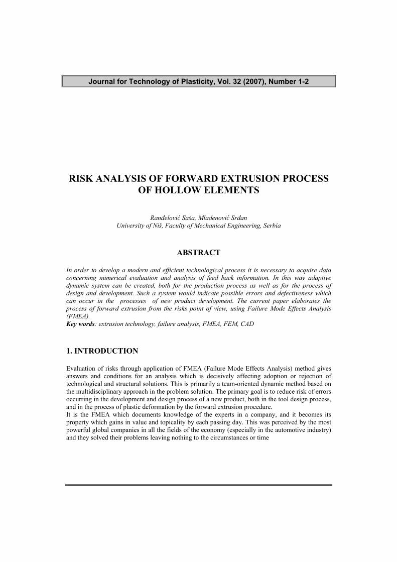
Figure 1 - The risk analysis for every parts in automotive industry today 2. RISK ANALYSIS APPLICATION Application of the FMEA at the company level or at a level of some of its parts, requires a special methodology and approach [1,2,5,8]. Primarily, what is needed is the willingness and consent of the highest management to implement such a method into an existing business system. The entire methodology consists of several steps which come in certain sequence and are mutually dependable [85]. It is necessary to collect and record all the possible errors irrespective whether the probability of their occurrence, that is, their consequences, is low or high. For each of the stated errors it is necessary to give all possible causes as well as countermeasures for their prevention and correction.
Figure 2 - Data base of failure define(FMEA, © CIM College)
Journal for Technology of Plasticity, Vol. 32 (2007), Number 1-2
59
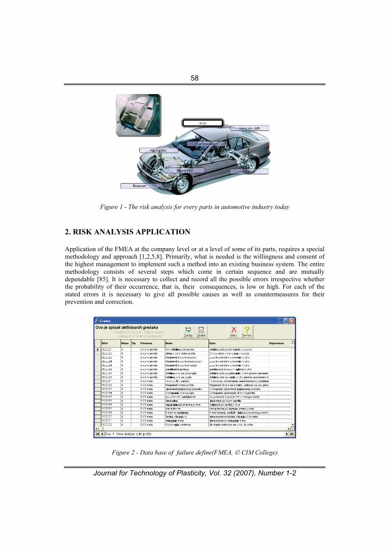
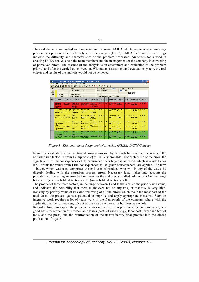
The said elements are unified and connected into a created FMEA which processes a certain mega process or a process which is the object of the analysis (Fig. 3). FMEA itself and its recordings indicate the difficulty and characteristics of the problem processed. Numerous tools used in creating FMEA analysis help the team members and the management of the company in correcting of perceived errors. The essence of the analysis is an assessment and evaluation of the problem prior to and after the carried out correction. Without an assessment and evaluation system, the real effects and results of the analysis would not be achieved.
Figure 3 - Risk analysis at design tool of extrusion (FMEA, © CIM College)
Numerical evaluation of the mentioned errors is assessed by the probability of their occurrence, the so called risk factor R1 from 1 (improbable) to 10 (very probable). For each cause of the error, the significance of the consequences of its occurrence for a buyer is assessed, which is a risk factor R2. For this the values from 1 (no consequences) to 10 (grave consequences) are applied. The term – buyer, which was used comprises the end user of product, who will in any of the ways, be directly dealing with the extrusion process errors. Necessary factor takes into account the probability of detecting an error before it reaches the end user, so called risk factor R3 in the range between 1 (very probable detection) to 10 (improbable detection) [7,8,9]. The product of these three factors, in the range between 1 and 1000 is called the priority risk value, and indicates the possibility that there might even not be any risk, or that risk is very high. Ranking by priority value of risk and removing of all the errors which make the most part of the total costs, the process gains a potential to improve and apply appropriate measures. Such an intensive work requires a lot of team work in the framework of the company where with the application of the software significant results can be achieved in business as a whole. Regarded from this aspect, the perceived errors in the extrusion process of the end products give a good basis for reduction of irredeemable losses (costs of used energy, labor costs, wear and tear of tools and the press) and the reintroduction of the unsatisfactory final product into the closed production life cycle.

Journal for Technology of Plasticity, Vol. 32 (2007), Number 1-2
60
Figure 4 - FMEA tool design, display of hierarchy (FMEA, © CIM College) As this is a series of consecutive technologies, mutually connected so that a high quality of the final product could be achieved, the perceived errors can occur in the extrusion process (Fig. 5), but can also be caused by the previous production procedures [15,16,]. In this way their influence is accumulated, and only at the end of the production process it is manifested as a key deficiency which cannot be rectified (e.g., poor quality of aluminum in the foundry will result in waste casting which would not allow a quality extruded elements).
Figure 5 - Failure of final extrusion elements The concept of error in such a mega process must be understood very widely, as it is possible in various levels. Namely, the errors made by the company management in creating the business policy of the company and the entire business can have catastrophic effects on the survival of the entire company and vice versa. Making a right decision and a business move would surely result in a positive outcome. It is certain that the analysis of errors at this level is much bigger challenge and requires a particular approach to the problems. On the other hand, the errors occurring within the production processes are far less serious and can be corrected relatively easily. Such errors are the most dangerous if they are left unattended; if they are not detected upon occurring and they
Journal for Technology of Plasticity, Vol. 32 (2007), Number 1-2
61
tend to accumulate. For a simple reason, their early detection alarms the corresponding sub-processes and procedures which then prevent errors, and minimize the financial damage of the error. However, if such errors remain undetected in good time, they can incur huge financial losses and damage the company image for a long period. This is particularly true in an environment of a dynamic market production requiring small series of products with new and very diverse requirements. 3. MODELING TOOL PARTS IN THE PLASTICITY DEFORMATION AREA ON THE BASIS OF FMEA ANALYSIS
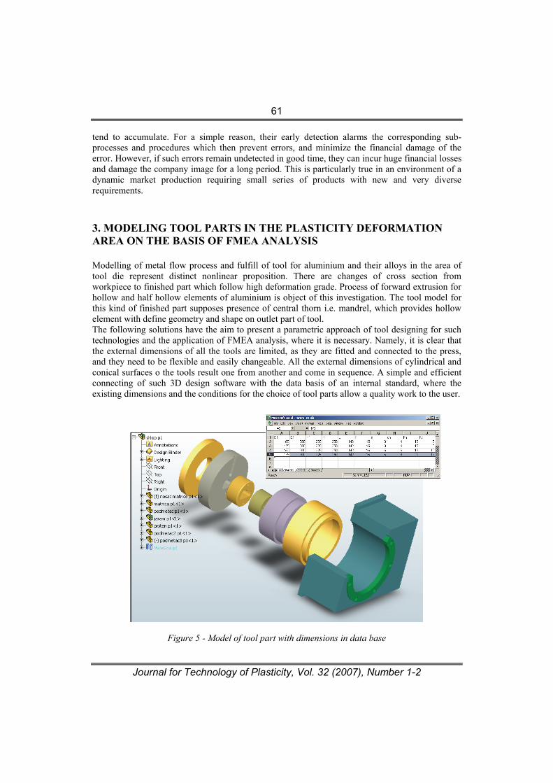
Modelling of metal flow process and fulfill of tool for aluminium and their alloys in the area of tool die represent distinct nonlinear proposition. There are changes of cross section from workpiece to finished part which follow high deformation grade. Process of forward extrusion for hollow and half hollow elements of aluminium is object of this investigation. The tool model for this kind of finished part supposes presence of central thorn i.e. mandrel, which provides hollow element with define geometry and shape on outlet part of tool. The following solutions have the aim to present a parametric approach of tool designing for such technologies and the application of FMEA analysis, where it is necessary. Namely, it is clear that the external dimensions of all the tools are limited, as they are fitted and connected to the press, and they need to be flexible and easily changeable. All the external dimensions of cylindrical and conical surfaces o the tools result one from another and come in sequence. A simple and efficient connecting of such 3D design software with the data basis of an internal standard, where the existing dimensions and the conditions for the choice of tool parts allow a quality work to the user.
Figure 5 - Model of tool part with dimensions in data base
Journal for Technology of Plasticity, Vol. 32 (2007), Number 1-2
62
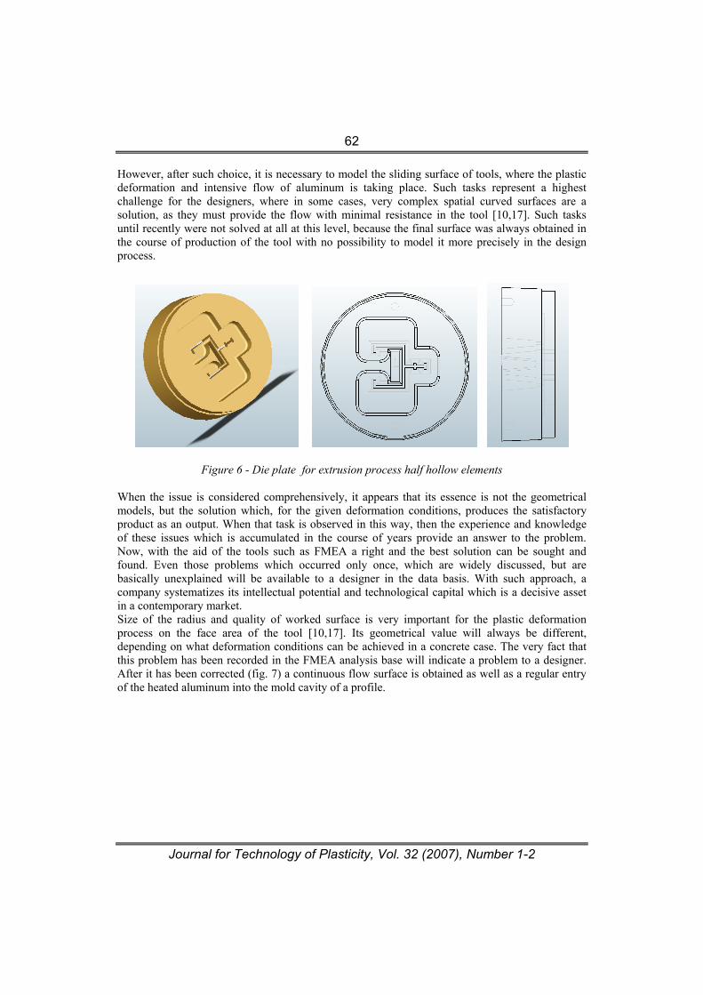
However, after such choice, it is necessary to model the sliding surface of tools, where the plastic deformation and intensive flow of aluminum is taking place. Such tasks represent a highest challenge for the designers, where in some cases, very complex spatial curved surfaces are a solution, as they must provide the flow with minimal resistance in the tool [10,17]. Such tasks until recently were not solved at all at this level, because the final surface was always obtained in the course of production of the tool with no possibility to model it more precisely in the design process.
Figure 6 - Die plate for extrusion process half hollow elements
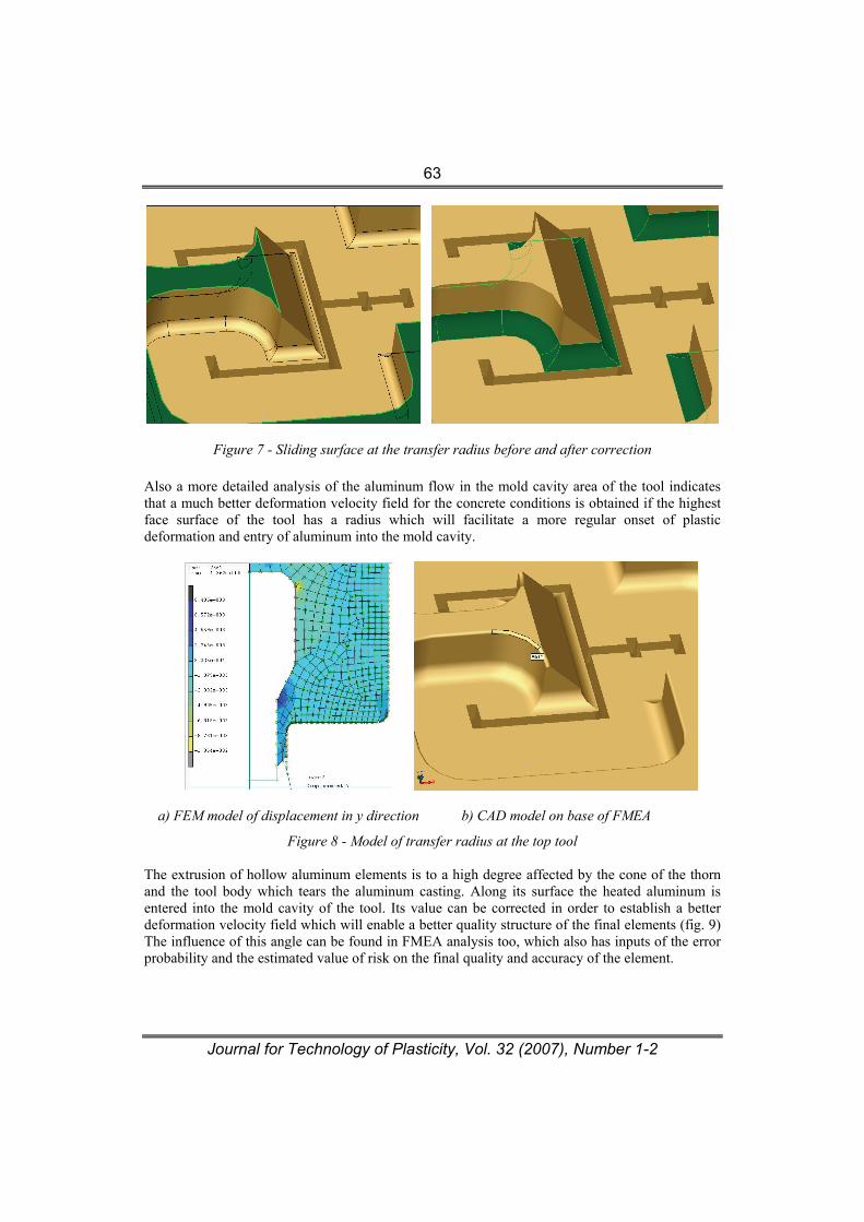
When the issue is considered comprehensively, it appears that its essence is not the geometrical models, but the solution which, for the given deformation conditions, produces the satisfactory product as an output. When that task is observed in this way, then the experience and knowledge of these issues which is accumulated in the course of years provide an answer to the problem. Now, with the aid of the tools such as FMEA a right and the best solution can be sought and found. Even those problems which occurred only once, which are widely discussed, but are basically unexplained will be available to a designer in the data basis. With such approach, a company systematizes its intellectual potential and technological capital which is a decisive asset in a contemporary market. Size of the radius and quality of worked surface is very important for the plastic deformation process on the face area of the tool [10,17]. Its geometrical value will always be different, depending on what deformation conditions can be achieved in a concrete case. The very fact that this problem has been recorded in the FMEA analysis base will indicate a problem to a designer. After it has been corrected (fig. 7) a continuous flow surface is obtained as well as a regular entry of the heated aluminum into the mold cavity of a profile.
Journal for Technology of Plasticity, Vol. 32 (2007), Number 1-2
63
Figure 7 - Sliding surface at the transfer radius before and after correction Also a more detailed analysis of the aluminum flow in the mold cavity area of the tool indicates that a much better deformation velocity field for the concrete conditions is obtained if the highest face surface of the tool has a radius which will facilitate a more regular onset of plastic deformation and entry of aluminum into the mold cavity.
a) FEM model of displacement in y direction b) CAD model on base of FMEA
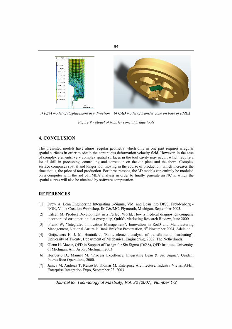
Figure 8 - Model of transfer radius at the top tool The extrusion of hollow aluminum elements is to a high degree affected by the cone of the thorn and the tool body which tears the aluminum casting. Along its surface the heated aluminum is entered into the mold cavity of the tool. Its value can be corrected in order to establish a better deformation velocity field which will enable a better quality structure of the final elements (fig. 9) The influence of this angle can be found in FMEA analysis too, which also has inputs of the error probability and the estimated value of risk on the final quality and accuracy of the element.
Journal for Technology of Plasticity, Vol. 32 (2007), Number 1-2
64
a) FEM model of displacement in y direction b) CAD model of transfer cone on base of FMEA
Figure 9 - Model of transfer cone at bridge tools
4. CONCLUSION The presented models have almost regular geometry which only in one part requires irregular spatial surfaces in order to obtain the continuous deformation velocity field. However, in the case of complex elements, very complex spatial surfaces in the tool cavity may occur, which require a lot of skill in processing, controlling and correction on the die plate and the thorn. Complex surface comprises spatial and longer tool moving in the course of production, which increases the time that is, the price of tool production. For these reasons, the 3D models can entirely be modeled on a computer with the aid of FMEA analysis in order to finally generate an NC in which the spatial curves will also be obtained by software computation. REFERENCES [1] Drew A, Lean Engineering Integrating 6-Sigma, VM, and Lean into DfSS, Freudenberg -
NOK, Value Creation Workshop, IMC&JMC, Plymouth, Michigan, September 2003. [2] Eileen M, Product Development in a Perfect World, How a medical diagnostics company
incorporated customer input at every step, Quirk's Marketing Research Review, June 2000 [3] Frank W, "Integrated Innovation Management", Innovation in R&D and Manufacturing
Management, National Australia Bank Brakfast Presentation, 5th November 2004, Adelaide [4] Geijselaers H. J. M, Heutnik J, "Finite element analysis of transformation hardening",
University of Twente, Department of Mechanical Engineering, 2002, The Netherlands. [5] Glenn H. Mazur, QFD in Support of Design for Six Sigma (DfSS), QFD Institute, University
of Michigan, Ann Arbor, Michigan, 2003 [6] Heriberto D., Manuel M. "Process Excellence, Integrating Lean & Six Sigma", Guidant
Puerto Rico Operations, 2000. [7] Janica M, Andreas T, Renzo B, Thomas M, Enterprise Architecture: Industry Views, AFEI,
Enterprise Integration Expo, September 23, 2003

Journal for Technology of Plasticity, Vol. 32 (2007), Number 1-2
65
[8] Jong G. S, Jung W. L, Technology Strategy in Korean Leading Edge Companies, Science and Technology Policy Institute (STEPI) Korea, November 2002
[9] John C, A framework for manufacturing innovation, Prepared for The Right Place, Inc. Manufactures Council, Draft 5.0, February, 2005
[10] Kojić M, "Computational procedures in inelastic analysis of solids and structures", Center for Scientific Research of Serbian Academy of Sciences and Arts and University of Kragujevac, 1997
[11] Majstorović, V, Digital factory – Fiction, Reality or Future, XXX JUPITER Conference, Beograd, 2004
[12] Plančak M, Vilotić D, Čupković Đ, "One contribution to the research of flow divide in bulk metal forming", Journal for Technology of Plasticity, pp. 48-56, vol. 26, Novi Sad 2001
[13] Ranđelović S, Mladenović S, Milosavljević P, Production of Aluminium Structures with Extrusion Technology Support QFD method, 12th International CIRP Life Cycle Engineering Seminar, Belgrade 2005.
[14] Ranđelović S, Stoiljković V, Bogdanov Lj, "Metal flow Modeling at the Forward Extrusion in the Shape Changing Area", The 13th International DAAAM symposium "Intelligent Manufacturing &Automation: Learning from Nature", 23-26th, October 2002, Viena, Austria.
[15] Ranđelović S, Stoiljković V, Modular approach at design of extrusion technology, Journal for Technology of Plasticity, vol. 25, 1-2, pp.45-58, Novi Sad, 2000.
[16] Ranđelović S, Modeliranje procesa istosmernog istiskivanja šupljih elemenata koji obezbeđuje visoku sposobnost procesa, Doktorska disertacija, pp.149, Niš, Oktobar 2006.
[17] Rens, Bas J. E. van "Finite element simulation of the aluminium extrusion process, shape predictions for complex profiles", Ph.D. thesis, Technische Universiteit Eindhoven, pp. 111, 1999,
[18] Stoiljković V, Veljković B, Stoiljković P, Jevremović D, Promenama do svetske klase, CIM College – Mašinski fakultet Niš, 1998, Niš
Journal for Technology of Plasticity, Vol. 32 (2007), Number 1-2
66
ANALIZA RIZIKA PRI ISTOSMERNOM ISTISKIVANJU
ŠUPLJIH ELEMENATA
Ranđelović Saša, Mladenović Srđan Univerzitet u Nišu, Mašinski fakultet, Aleksandra Medvedeva 14, 18000 Niš, Srbija
e-mail: [email protected]
REZIME Jedan zaokruženi i potpuni sistem projektovanja tehnologije istosmernog istiskivanja šupljih profila dobija na snazi ukoliko je on baziran na realnim parametrima i pokazateljima koji imaju odlučujuću ulogu na njegov tok. Da bi dobili jedan savremen tehnološki process pruža se mogućnost prikupljanja, evidentiranja, numeričkog vrednovanja i analize povratnih informacija. Dobija se jedan adaptivni dinamičan sistem kako u samom proizvodnom procesu, tako i u procesu projektovanja i razvoja ka menadžmentu kompanije, o njegovim greškama, nedostacima i zapažanjima.