rig hd - steadicam | products | rental |service | betz ... · betz-tools.com rig hd ... the...
TRANSCRIPT

betz-tools.com
RIG HD
Manual
”STAGE”
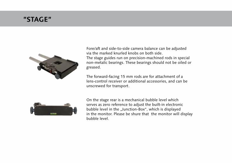
Fore/aft and side-to-side camera balance can be adjusted via the marked knurled knobs on both side. The stage guides run on precision-machined rods in special non-metalic bearings. These bearings should not be oiled or greased.
The forward-facing 15 mm rods are for attachment of a lens-control receiver or additional accessories, and can be unscrewed for transport.
On the stage rear is a mechanical bubble level which serves as zero reference to adjust the built-in electronic bubble level in the „Junction-Box“, which is displayed in the monitor. Please be shure that the monitor will displaybubble level.

Attach camera with mounted dovetail plate from above. Make sure that the clamp lever on the stage faces to the rear (A) so that the clamping is open. After the camera snaps in, the clamp lever comes into a middle position and the safety pin (B) springs up.The camera is now protected against sliding out. By pulling the clamp lever towards stage rear, approximate fore/aft balance can now be achieved by sliding of the camera in the stage.The clamping lever should lock the camera even before being pressed to the final stop! In case the camera can still be moved even though the lever is pressed until stop, a spacer of approx. 0,1 mm has to be put under the compensation track (C) under the cover plate.
To remove the camera, the dovetail clamp must be opened by pulling the clamp lever fully to stage rear. In order to do this, you will have to press down the safety pin (A).Important! The screw (B) under the cover plate which fixes the clamping lever must never be unscrewed, this could damage the mechanism. Should this screw be loosened accidentally, it should be secured with Loctite 603. Maintenance: The locking mechanism should be treated/cleaned occasionally with a resinless oil (e.g. gun oil).
Mounting the Camera ”SAFETY LOCK”
AB
C
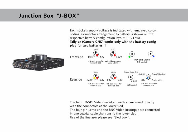
Each sockets supply voltage is indicated with engraved color-coding. Connector arrangement to battery is shown on the respective battery configuration layout (RIG-Low) .Tally on (Camera GND) works only with the battery config plug for two batteries !!
Frontside
Rearside
The two HD-SDI Video in/out connectors are wired directly with the connectors at the lower sled.The four-pin Lemo and the BNC Video in/output are connected in one coaxial cable that runs to the lower sled.Use of the linelaser please see ”Sled Low”.
Junction Box ”J-BOX”
+12V
GND
sold. side connectorLemo 1B 303
Tally +12V
GND
sold. side connectorLemo 1B 303
HD-SDI VideoBNC isolated
+12V
GND
sold. side connectorLemo 1B 303
+24V +12V
GND
sold. side connectorLemo 1B 303
Video
Analog Video Gnd
BNC isolatedsold. side connector
Lemo 0B 304
AnalogVideo Gnd
Analog Video+12V
Gnd 12V
Tally
Electronic Bubble-Level
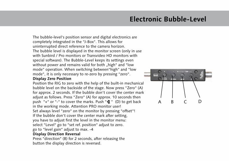
The bubble-level‘s position sensor and digital electronics are completely integrated in the “J-Box“. This allows for uninterrupted direct reference to the camera horizon. The bubble level is displayed in the monitor screen (only in use with Sunbird / Pro monitors or Transvideo HD monitors with special software). The Bubble-Level keeps its settings even without power and remains valid for both „high“ and “low mode“ operation. When switching between“high“ and “low mode“, it is only necessary to re-zero by pressing “zero“.Display Zero PositionPosition the RIG to zero with the help of the built-in mechanical bubble level on the backside of the stage. Now press “Zero“ (A) for approx. 2 seconds. If the bubble don‘t cover the center mark adjust as follows. Press “Zero“ (A) for approx. 10 seconds then push “+“ or “-“ to cover the marks. Push “ “ (D) to get back in the working mode. Attention PRO monitor user!Set always level “zero“ on the monitor by pressing “offset“!If the bubble don‘t cover the center mark after setting, you have to adjust first the level in the monitor menu:select “Level“ go to “set ref. position“ adjust to zero.go to “level gain“ adjust to max. -4Display Direction ReversalPress “direction“ (B) for 2 seconds, after releasing the button the display direction is reversed.
A B C D
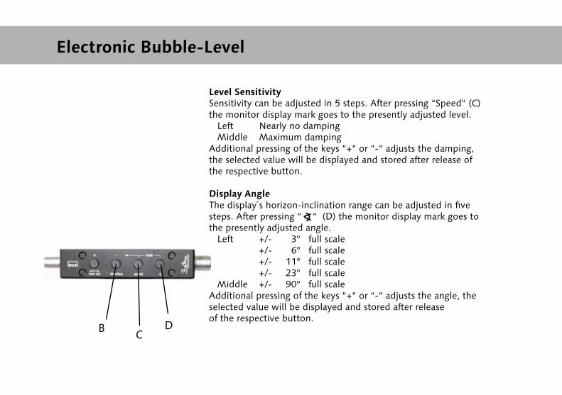
Level SensitivitySensitivity can be adjusted in 5 steps. After pressing “Speed“ (C) the monitor display mark goes to the presently adjusted level. Left Nearly no damping Middle Maximum damping Additional pressing of the keys “+“ or “-“ adjusts the damping, the selected value will be displayed and stored after release of the respective button.
Display AngleThe display`s horizon-inclination range can be adjusted in five steps. After pressing “ “ (D) the monitor display mark goes to the presently adjusted angle. Left +/- 3° full scale +/- 6° full scale +/- 11° full scale +/- 23° full scale Middle +/- 90° full scaleAdditional pressing of the keys “+“ or “-“ adjusts the angle, the selected value will be displayed and stored after release of the respective button.
Electronic Bubble-Level
B CD
Removing ”STAGE /J-BOX”
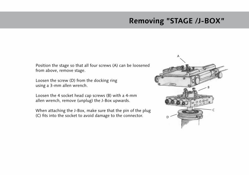
Position the stage so that all four screws (A) can be loosened from above, remove stage.
Loosen the screw (D) from the docking ring using a 3-mm allen wrench.
Loosen the 4 socket head cap screws (B) with a 4-mm allen wrench, remove (unplug) the J-Box upwards.
When attaching the J-Box, make sure that the pin of the plug (C) fits into the socket to avoid damage to the connector.
A
B
C
D
”Gimbal”
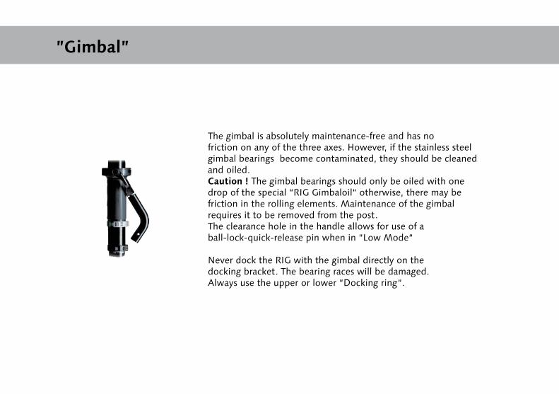
The gimbal is absolutely maintenance-free and has no friction on any of the three axes. However, if the stainless steel gimbal bearings become contaminated, they should be cleaned and oiled.Caution ! The gimbal bearings should only be oiled with one drop of the special “RIG Gimbaloil“ otherwise, there may be friction in the rolling elements. Maintenance of the gimbal requires it to be removed from the post.The clearance hole in the handle allows for use of a ball-lock-quick-release pin when in “Low Mode“
Never dock the RIG with the gimbal directly on the docking bracket. The bearing races will be damaged. Always use the upper or lower “Docking ring“.

Post
The telescopic post can be extended in four increments.Each post segment is marked to show the maximumextension limit.“CAUTION LIMIT“ The mark shows the maximum safe extension limit; past this mark, the post tubes may slide out (or slip), even while clamped.For “Low mode“ operation an additional lock has to be attached to the camera.
Caution! When adjusting the post (extension or retraction of post segments), hold both adjusted post segments firmly with both hands; the spiral cable in the post could exert tension and pull the segments together unexpectedly, causing injury.Release the post segments only when the respective clamp has been locked. It can occur, that the post cannot be pushed back to its minimum length. This is due to turning the post segments against each other too often. In order to solve the problem, simply open the clamp and twist the upper segment clockwise as many times as necessary until the segment can be pushed back completely again.
Adjustment of Post Clamps
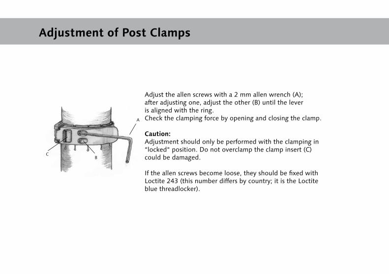
Adjust the allen screws with a 2 mm allen wrench (A); after adjusting one, adjust the other (B) until the lever is aligned with the ring. Check the clamping force by opening and closing the clamp.
Caution: Adjustment should only be performed with the clamping in “locked“ position. Do not overclamp the clamp insert (C) could be damaged.
If the allen screws become loose, they should be fixed withLoctite 243 (this number differs by country; it is the Loctite blue threadlocker).
A
BC
Sled Low ”RIG LOW/BASE”
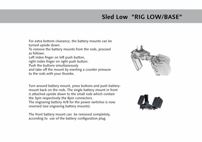
For extra bottom clearance, the battery mounts can be turned upside down.To remove the battery mounts from the rods, proceed as follows:Left index finger on left push button,right index finger on right push button.Push the buttons simultaneouslyand take off the mount by exerting a counter pressure to the rods with your thumbs.
Turn around battery mount, press buttons and push battery-mount back on the rods. The single battery mount in front is attached upside down to the small rods which contain the 3pin respectively the 8pin connectors.The engraving battery A/B for the power switches is now reversed (see engraving battery mounts).
The front battery mount can be removed completely, according to use of the battery configuration plug.
Power switches - Fuses
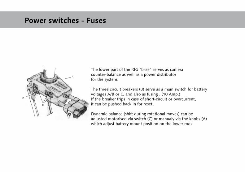
The lower part of the RIG “base“ serves as camera counter-balance as well as a power distributor for the system.
The three circuit breakers (B) serve as a main switch for battery voltages A/B or C, and also as fusing . (10 Amp.)If the breaker trips in case of short-circuit or overcurrent, it can be pushed back in for reset.
Dynamic balance (shift during rotational moves) can be adjusted motorised via switch (C) or manualy via the knobs (A) which adjust battery mount position on the lower rods.
A
B
c
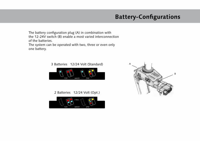
3 Batteries 12/24 Volt (Standard)
2 Batteries 12/24 Volt (Opt.)
Battery-Configurations
A
B
The battery configuration plug (A) in combination with the 12-24V switch (B) enable a most varied interconnection of the batteries. The system can be operated with two, three or even only one battery.
24V12V switch
24V12V switch
2 Batt.

Batterie Display / Linelaser / setup
The battery capacity is displayed in levels of 10%.
Attention: When using NIMH- or L-ion batteries display can showwrong datas. NICAD batteries will display properly with their characteristic curves.
The integrated switchable linelaser which is built in the”J-Box” is used for the correct adjustment from thelower sled part to sled top part. The reference marks next to the battery display are to line up.The marks from the linelaser on the floor can be used asreference marks while shooting.
Referencemarks
Referencemarks
Laserline
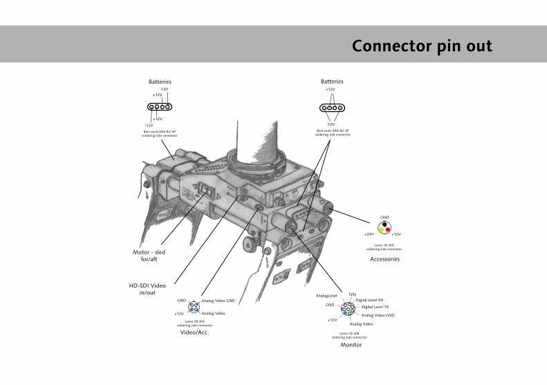
Connector pin out
+12V
-12V
-12V
-12V
+12V
+12V
Betz-tools RAK BU 4Psoldering side connector
Betz-tools RAK BU 4Psoldering side connector
Lemo 1B 303soldering side connector
+12V+24V
GND
Accessories
Lemo 0B 304soldering side connector
+12V
GND
Analog Video
Analog Video GND
Video/Acc.
BatteriesBatteries
Lemo 1B 308soldering side connector
Analog Video GND
Analog Video
TallyAnalogLevel
+12V
GND
Monitor
Digital Level RX
Digital Level TX
HD-SDI Video in/out
Motor - sledfor/aft
Accessory Adapters
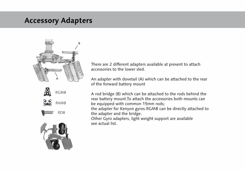
There are 2 different adapters available at present to attachaccessories to the lower sled.
An adapter with dovetail (A) which can be attached to the rear of the forward battery mount
A rod bridge (B) which can be attached to the rods behind the rear battery mount.To attach the accessories both mounts can be equipped with common 15mm rods; the adapter for Kenyon gyros RGMB can be directly attached to the adapter and the bridge.Other Gyro adapters, light weight support are availablesee actual list.
RAMB
RDB
RGMB
B
A
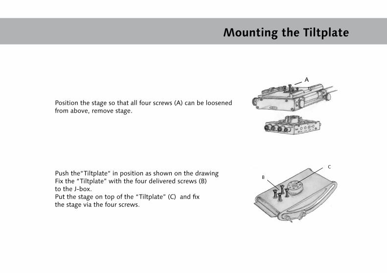
Mounting the Tiltplate
A
C
B
Position the stage so that all four screws (A) can be loosened from above, remove stage.
Push the“Tiltplate“ in position as shown on the drawing Fix the “Tiltplate” with the four delivered screws (B) to the J-box. Put the stage on top of the “Tiltplate” (C) and fix the stage via the four screws.

Any Question?