rider'smanual r1200rt - káli-medence · 7 switch, high-beam head-light and headlight flash-er...
TRANSCRIPT
BMW Motorrad
Freude am Fahren
Rider's ManualR 1200 RT

Motorcycle data/dealership details
Motorcycle data
Model
Vehicle identification number
Colour code
Date of first registration
Registration number
Dealership details
Person to contact in Service depart-
ment
Ms/Mr
Phone number
Dealership address/phone number
(company stamp)
Welcome to BMW
We congratulate you on your
choice of a motorcycle from
BMW and welcome you to the
community of BMW riders.
Familiarise yourself with your
new motorcycle so that you
can ride it safely and confid-
ently in all traffic situations.
Please read this Rider's
Manual carefully before
starting to use your new
BMW motorcycle. It contains
important information on
how to operate the controls
and how to make the best
possible use of all your
BMW's technical features.
In addition, it contains inform-
ation on maintenance and
care to help you maintain your
motorcycle's reliability and
safety, as well as its value.
If you have any questions
concerning your motorcycle,
your authorised BMW Motor-
rad dealer will gladly provide
advice and assistance.
We hope that you will enjoy
riding your BMW and that all
your journeys will be pleasant
and safe.
BMW Motorrad.

Table of Contents
You can also consult the in-
dex at the end of this Rider's
Manual if you want to find a
particular topic or item of in-
formation.
1 General instructions . . . 5Overview . . . . . . . . . . . . . . . . . 6
Abbreviations and
symbols . . . . . . . . . . . . . . . . . . 6
Equipment . . . . . . . . . . . . . . . 7
Technical data. . . . . . . . . . . . 7
Currency . . . . . . . . . . . . . . . . . 7
2 General views . . . . . . . . . 9General view, left side . . . 11
General view, right
side. . . . . . . . . . . . . . . . . . . . . 13
Underneath the seat . . . . . 15
Handlebar fitting, left . . . . . 16
Handlebar fitting, right . . . 17
Instrument cluster . . . . . . . 18
Headlight . . . . . . . . . . . . . . . 19
3 Status indicators . . . . . 21Multifunction display . . . . . 22
Warning and telltale
lights . . . . . . . . . . . . . . . . . . . 23
ABS warning light . . . . . . . 23
Function indicators . . . . . . 23
Warnings, general . . . . . . . 23
ABS warning
indicators . . . . . . . . . . . . . . . 30
4 Operation. . . . . . . . . . . . . 37Ignition switch and
steering lock . . . . . . . . . . . . 38
Electronic immobiliser
(EWS) . . . . . . . . . . . . . . . . . . . 39
Hazard warning
flashers . . . . . . . . . . . . . . . . . 40
Odometer and
tripmeters . . . . . . . . . . . . . . . 41
Clock . . . . . . . . . . . . . . . . . . . 42
Multifunction display . . . . . 42
On-board computerOE . . . 43
Cruise-control
systemOE. . . . . . . . . . . . . . . . 46
Emergency off switch (kill
switch) . . . . . . . . . . . . . . . . . . 48
Grip heatingOE. . . . . . . . . . . 49
Seat heatingOE . . . . . . . . . . 49
Clutch . . . . . . . . . . . . . . . . . . 51
Brakes . . . . . . . . . . . . . . . . . . 52
Lights . . . . . . . . . . . . . . . . . . . 52
Headlight . . . . . . . . . . . . . . . 54
Turn indicators . . . . . . . . . . 55
Stowage compartment . . . 56
Front and rear seats . . . . . 57
Helmet holder . . . . . . . . . . . 60
Mirrors . . . . . . . . . . . . . . . . . . 60
Windscreen . . . . . . . . . . . . . 61
Spring preload . . . . . . . . . . 61
Shock absorbers . . . . . . . . 62
Electronic Suspension
Adjustment ESAOE . . . . . . . 63
Tyres . . . . . . . . . . . . . . . . . . . 65
5 Riding . . . . . . . . . . . . . . . . 67Safety instructions . . . . . . . 68
Checklist . . . . . . . . . . . . . . . . 70
Starting . . . . . . . . . . . . . . . . . 70
Pulling away . . . . . . . . . . . . . 72
Running in . . . . . . . . . . . . . . 73
Parking your
motorcycle . . . . . . . . . . . . . . 77
Refuelling . . . . . . . . . . . . . . . 84
Brake system, general . . . 85
Brake system with BMW
Integral ABS. . . . . . . . . . . . . 86
6 Accessories . . . . . . . . . . 89General instructions . . . . . 90
Power socket . . . . . . . . . . . 90
Luggage . . . . . . . . . . . . . . . . 93
Case. . . . . . . . . . . . . . . . . . . . 94
TopcaseOA . . . . . . . . . . . . . . 96
7 Maintenance . . . . . . . . . 99General instructions . . . . 100
Toolkit . . . . . . . . . . . . . . . . . 100
Overview, toolkit . . . . . . . . 100
Supplementary kitOA . . . . 100
Overview, supplementary
kit . . . . . . . . . . . . . . . . . . . . . 101
Engine oil . . . . . . . . . . . . . . 101
Brake system,
general . . . . . . . . . . . . . . . . 102
Brake pads. . . . . . . . . . . . . 103
Brake fluid . . . . . . . . . . . . . 105
Clutch . . . . . . . . . . . . . . . . . 107
Tyres . . . . . . . . . . . . . . . . . . 107
Rims . . . . . . . . . . . . . . . . . . . 108
Wheels. . . . . . . . . . . . . . . . . 108
Front wheel stand . . . . . . 114
Bulbs . . . . . . . . . . . . . . . . . . 116
Jump starting . . . . . . . . . . 125
Battery . . . . . . . . . . . . . . . . . 126
8 Care . . . . . . . . . . . . . . . . . 131Care products . . . . . . . . . . 132
Washing the
motorcycle . . . . . . . . . . . . . 132
Cleaning easily damaged
components. . . . . . . . . . . . 133
Paint care . . . . . . . . . . . . . . 134
Protective wax
coating . . . . . . . . . . . . . . . . 134
Laying up the
motorcycle . . . . . . . . . . . . . 134
Restoring motorcycle to
use . . . . . . . . . . . . . . . . . . . . 135
9 Technical data . . . . . . . 137Troubleshooting
chart . . . . . . . . . . . . . . . . . . . 138
Threaded fasteners . . . . . 138
Engine . . . . . . . . . . . . . . . . . 139
Riding specifications . . . . 141
Clutch . . . . . . . . . . . . . . . . . 142
Transmission . . . . . . . . . . . 142
Rear-wheel drive . . . . . . . 143
Running gear . . . . . . . . . . . 143
Brakes . . . . . . . . . . . . . . . . . 144
Wheels and tyres . . . . . . . 145
Electrics . . . . . . . . . . . . . . . 146
Frame. . . . . . . . . . . . . . . . . . 148
Dimensions . . . . . . . . . . . . 148
Weights . . . . . . . . . . . . . . . . 149
10 Service . . . . . . . . . . . . . 151BMW Motorrad
service . . . . . . . . . . . . . . . . . 152
BMW Motorrad service
quality . . . . . . . . . . . . . . . . . 152
BMW Motorrad Service
Card: On-the-spot
breakdown
assistance . . . . . . . . . . . . . 153
BMW Motorrad service
network . . . . . . . . . . . . . . . . 153
Maintenance work . . . . . . 153
Maintenance
schedules . . . . . . . . . . . . . . 154
Confirmation of
maintenance work . . . . . . 155

Confirmation of
service . . . . . . . . . . . . . . . . . 160
General instructions
Overview. . . . . . . . . . . . . . . . . . . . . . . . 6
Abbreviations and symbols . . . . . . 6
Equipment . . . . . . . . . . . . . . . . . . . . . . 7
Technical data . . . . . . . . . . . . . . . . . . 7
Currency . . . . . . . . . . . . . . . . . . . . . . . . 7
15
z Ge
ne
ral i
nst
ruc
tio
ns

OverviewChapter 2 of this Rider's
Manual will provide you with
an initial overview of your
motorcycle. All maintenance
and servicing work on the
motorcycle is documented in
Chapter 10. This record of
the maintenance work you
have had performed on your
motorcycle is a precondition
for generous treatment of
claims submitted after the
warranty period has expired.
When the time comes to sell
your BMW, please remem-
ber to hand over this Rider's
Manual; it is an important part
of the motorcycle.
Abbreviations andsymbols
Indicates warnings that
you must comply with for
reasons of your safety and the
safety of others, and to pro-
tect your motorcycle against
damage.
Specific instructions on
how to operate, control,
adjust or look after items of
equipment on the motorcycle.
Indicates the end of an
item of information.
Instruction.
Result of an activity.
Reference to a page
with more detailed in-
formation.
OE Optional extra
Your motorcycle was
assembled complete
with all the BMW
optional extras you
ordered.
OA Optional accessory
You can obtain option-
al accessories through
your authorised BMW
Motorrad dealer; op-
tional accessories
have to be retrofitted
to the motorcycle.
EWS Electronic immobiliser
(Elektronische Weg-
fahrsicherung).
DWA Anti-theft alarm (Diebs-
tahlwarnanlage)
ABS Anti-lock brake system
16
z Ge
ne
ral i
nst
ruc
tio
ns

ESA Electronic Suspension
Adjustment
Electronic Suspension
Adjustment.
EquipmentWhen you ordered your BMW
motorcycle, you chose vari-
ous items of custom equip-
ment. This Rider's Manual
describes optional extras (OE)
offered by BMW and selec-
ted optional accessories (OA).
This explains why the manual
may also contain descriptions
of equipment which you have
not ordered. Please note, too,
that your motorcycle might
not be exactly as illustrated
in this manual on account of
country-specific differences.
If your BMW was supplied
with equipment not described
in this Rider's Manual, you will
find these features described
in separate manuals.
Technical dataAll dimensions, weights and
power ratings stated in the
Rider's Manual are quoted
to the standards and comply
with the tolerance require-
ments of the Deutsche Institut
für Normung e.V. (DIN). Ver-
sions for individual countries
may differ.
CurrencyThe high safety and quality
standards of BMW motor-
cycles are maintained by con-
stant development work on
designs, equipment and ac-
cessories. Because of this,
your motorcycle may differ
from the information supplied
in the Rider's Manual. Nor
can BMW Motorrad entirely
rule out errors and omissions.
We hope you will appreciate
that no claims can be en-
tertained on the basis of the
data, illustrations or descrip-
tions in this manual.17
z Ge
ne
ral i
nst
ruc
tio
ns

18
z Ge
ne
ral i
nst
ruc
tio
ns
General views
General view, left side . . . . . . . . . 11
General view, right side . . . . . . . . 13
Underneath the seat . . . . . . . . . . . 15
Handlebar fitting, left . . . . . . . . . . 16
Handlebar fitting, right . . . . . . . . . 17
Instrument cluster . . . . . . . . . . . . . 18
Headlight . . . . . . . . . . . . . . . . . . . . . 19
29
z Ge
ne
ral v
iew
s
210
z Ge
ne
ral v
iew
s
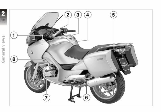
General view, left side1 Adjuster for headlight
beam throw underneath
the instrument cluster
( 54)
2 Brake-fluid reservoir
( 105)
3 Radio operating unit (OE)
4 Power socket ( 90)
5 On-board socket (OE)
( 90)
6 Adjuster, rear shock ab-
sorber ( 62)
7 Oil sight glass ( 101)
8 Filler neck, engine oil
( 102)
211
z Ge
ne
ral v
iew
s
212
z Ge
ne
ral v
iew
s

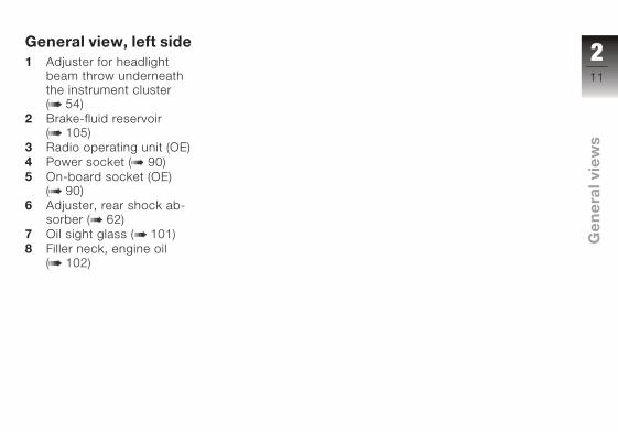
General view, rightside1 Seat lock ( 57)
2 Switch, rear-seat heating
(OE), underneath the rear
seat ( 50)
3 Mount for tank rucksack
(OE)
4 Filler neck, fuel tank
( 84)
5 Clutch-fluid reservoir
6 Electrically adjustable
windscreen ( 61)
7 Stowage compartment
or radio compartment
( 56)
213
z Ge
ne
ral v
iew
s
214
z Ge
ne
ral v
iew
s
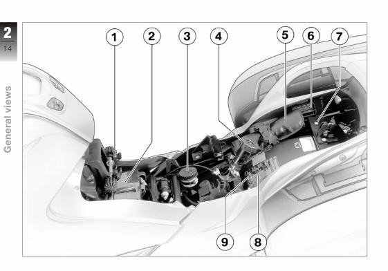
Underneath the seat1 Height adjuster, front
seat ( 58)
2 Battery ( 126)
3 Brake-fluid reservoir, rear
( 106)
4 Adjuster, spring preload,
rear ( 61)
5 Toolkit ( 100)
6 Type plate
7 Helmet holder ( 60)
8 Table of tyre pressures
9 Label, payload
215
z Ge
ne
ral v
iew
s

Handlebar fitting, left1 Switch for cruise-control
system (OE) ( 46)
2 Radio operating unit (OE)
3 ESA button (OE) ( 63)
4 Pushbutton, windscreen
adjustment ( 61)
5 Pushbutton, horn
6 Pushbutton, left flash-
ing turn indicators and
hazard warning flashers
( 55) ( 40)
7 Switch, high-beam head-
light and headlight flash-
er ( 53)
216
z Ge
ne
ral v
iew
s

Handlebar fitting, right1 On-board computer but-
ton (OE) ( 43)
2 Emergency off switch (kill
switch) ( 48)
3 Pushbutton, starter
4 with OE Heated handle-
bar grips:
Grip heating ( 49)
5 Pushbutton, right flash-
ing turn indicators and
hazard warning flashers
( 55) ( 40)
6 Cancel button, flashing
turn indicators ( 56)
7 Front-seat heating switch
( 50)
217
z Ge
ne
ral v
iew
s
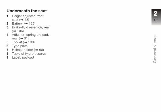
Instrument cluster1 Speedometer
2 Warning and telltale
lights ( 23)
3 Multifunction display
4 Rev. counter
5 Anti-theft alarm telltale
light
6 Button for setting clock
and dimming display
( 42) ( 42)
7 Control, odometer ( 41)
8 Sensor for instrument
cluster lighting
The instrument-cluster
lighting has automatic
day and night switchover.
218
z Ge
ne
ral v
iew
s
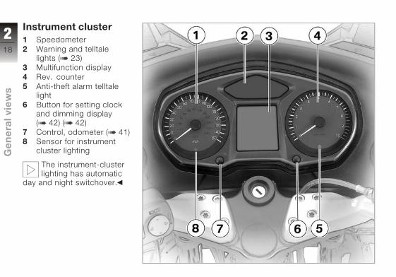
Headlight1 High-beam headlight
2 Low-beam headlight
3 Side lights
219
z Ge
ne
ral v
iew
s

220
z Ge
ne
ral v
iew
s
Status indicators
Multifunction display . . . . . . . . . . . 22
Warning and telltale lights . . . . . . 23
ABS warning light . . . . . . . . . . . . . 23
Function indicators . . . . . . . . . . . . 23
Warnings, general . . . . . . . . . . . . . 23
ABS warning indicators . . . . . . . . 30
321
z Sta
tus
ind
icat
ors

Multifunction display1 Fuel gauge ( 23)
2 Panel for radio (see in-
structions for use for ra-
dio)
3 Panel for warnings
( 23)
4 Gear indicator ( 23)
5 Engine temperature
readout ( 23)
6 Tripmeter or panel for
on-board computer (OE)
readings ( 41) ( 43)
7 Panel for clock, seat
heating (OE), display
dimmer and ESA (OE)
( 42) ( 49) ( 42)
( 63)
8 Odometer and tripmeters
( 41)
322
z Sta
tus
ind
icat
ors

Warning and telltalelights
1 Telltale light, left turn in-
dicator
2 Telltale light, high-beam
headlight
3 Telltale light, neutral
4 ABS warning light
5 Telltale light, right turn
indicator
6 Warning light, general
ABS warning lightThe way in which the ABS
warning light indicates status
can differ in some countries.
Alternative for the ABS
warning light.
Function indicatorsFuel capacity
The horizontal bars be-
low the fuel-pump sym-
bol indicate the remaining
quantity of fuel.
GearShows which gear is en-
gaged.
If no gear is engaged, the
gear indicator displays 0;
the 'neutral' telltale light also
lights up.
Engine temperatureThe horizontal bars
below the temperature
symbol indicate the engine
temperature.
Warnings, generalMode of presentationGeneral warnings are dis-
played by means of plain-text
messages and symbols in the
multifunction display. In some
cases, they are accompan-
ied by the 'General' warning
light showing red or yellow. A
number of warnings may be
issued simultaneously.
323
z Sta
tus
ind
icat
ors
7 Telltale light,
cruise control system
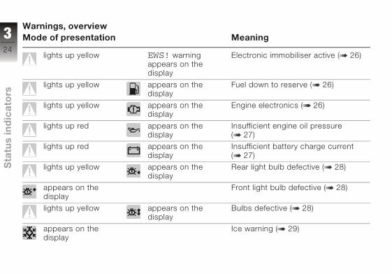
Warnings, overviewMode of presentation Meaning
lights up yellow EWS! warning
appears on the
display
Electronic immobiliser active ( 26)
lights up yellow appears on the
display
Fuel down to reserve ( 26)
lights up yellow appears on the
display
Engine electronics ( 26)
lights up red appears on the
display
Insufficient engine oil pressure
( 27)
lights up red appears on the
display
Insufficient battery charge current
( 27)
lights up yellow appears on the
display
Rear light bulb defective ( 28)
appears on the
display
Front light bulb defective ( 28)
lights up yellow appears on the
display
Bulbs defective ( 28)
appears on the
display
Ice warning ( 29)
324
z Sta
tus
ind
icat
ors
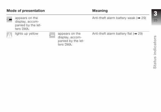
Mode of presentation Meaning
appears on the
display, accom-
panied by the let-
ters DWA.
Anti-theft alarm battery weak ( 29)
lights up yellow appears on the
display, accom-
panied by the let-
ters DWA.
Anti-theft alarm battery flat ( 29)
325
z Sta
tus
ind
icat
ors
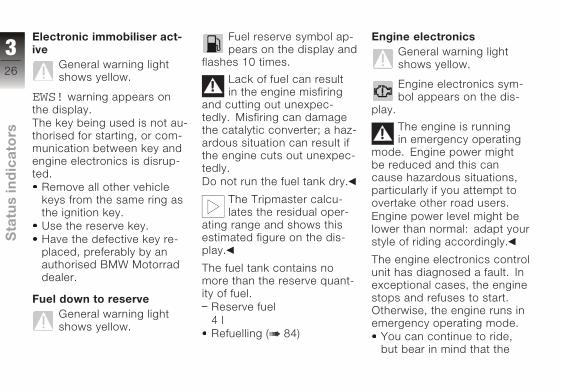
Electronic immobiliser act-ive
General warning light
shows yellow.
EWS! warning appears on
the display.
The key being used is not au-
thorised for starting, or com-
munication between key and
engine electronics is disrup-
ted.
Remove all other vehicle
keys from the same ring as
the ignition key.
Use the reserve key.
Have the defective key re-
placed, preferably by an
authorised BMW Motorrad
dealer.
Fuel down to reserveGeneral warning light
shows yellow.
Fuel reserve symbol ap-
pears on the display and
flashes 10 times.
Lack of fuel can result
in the engine misfiring
and cutting out unexpec-
tedly. Misfiring can damage
the catalytic converter; a haz-
ardous situation can result if
the engine cuts out unexpec-
tedly.
Do not run the fuel tank dry.
The Tripmaster calcu-
lates the residual oper-
ating range and shows this
estimated figure on the dis-
play.
The fuel tank contains no
more than the reserve quant-
ity of fuel.
Reserve fuel
4 l
Refuelling ( 84)
Engine electronicsGeneral warning light
shows yellow.
Engine electronics sym-
bol appears on the dis-
play.
The engine is running
in emergency operating
mode. Engine power might
be reduced and this can
cause hazardous situations,
particularly if you attempt to
overtake other road users.
Engine power level might be
lower than normal: adapt your
style of riding accordingly.
The engine electronics control
unit has diagnosed a fault. In
exceptional cases, the engine
stops and refuses to start.
Otherwise, the engine runs in
emergency operating mode.
You can continue to ride,
but bear in mind that the
326
z Sta
tus
ind
icat
ors
usual engine power might
not be available.
Have the fault rectified as
soon as possible by a spe-
cialist workshop, preferably
an authorised BMW Motor-
rad dealer.
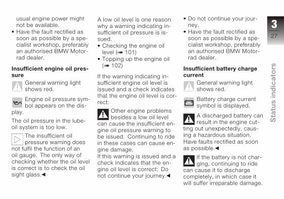
Insufficient engine oil pres-sure
General warning light
shows red.
Engine oil pressure sym-
bol appears on the dis-
play.
The oil pressure in the lube-
oil system is too low.
The insufficient oil
pressure warning does
not fulfil the function of an
oil gauge. The only way of
checking whether the oil level
is correct is to check the oil
sight glass.
A low oil level is one reason
why a warning indicating in-
sufficient oil pressure is is-
sued.
Checking the engine oil
level ( 101)
Topping up the engine oil
( 102)
If the warning indicating in-
sufficient engine oil level is
issued and a check indicates
that the engine oil level is cor-
rect:
Other engine problems
besides a low oil level
can cause the insufficient en-
gine oil pressure warning to
be issued. Continuing to ride
in these cases can cause en-
gine damage.
If this warning is issued and a
check indicates that the en-
gine oil level is correct: Do
not continue your journey.
Do not continue your jour-
ney.
Have the fault rectified as
soon as possible by a spe-
cialist workshop, preferably
an authorised BMW Motor-
rad dealer.
Insufficient battery chargecurrent
General warning light
shows red.
Battery charge current
symbol is displayed.
A discharged battery can
result in the engine cut-
ting out unexpectedly, caus-
ing a hazardous situation.
Have faults rectified as soon
as possible.
If the battery is not char-
ging, continuing to ride
can cause it to discharge
completely, in which case it
will suffer irreparable damage.
327
z Sta
tus
ind
icat
ors

If possible, do not continue
your journey.
Battery is not being charged.
You can continue to
ride until the battery is
discharged. Bear in mind,
however, that the engine
could cut out suddenly
and that the battery could
discharge until completely
flat, in which case it might
have suffered irreparable
damage.
Have the fault rectified as
soon as possible by a spe-
cialist workshop, preferably
an authorised BMW Motor-
rad dealer.
Rear light bulb defectiveGeneral warning light
shows yellow.
Defective bulb symbol
with arrow pointing to
the rear appears on the dis-
play.
A defective bulb places
your safety at risk be-
cause it is easier for other
users to oversee you and
your motorcycle.
Replace defective bulbs as
soon as possible; always
carry a complete set of spare
bulbs if possible.
Rear light or brake light bulb
defective.
Replacing brake-light, rear
light and rear-indicator
bulbs ( 123)
Front light bulb defectiveDefective bulb symbol
with arrow pointing to
the front appears on the dis-
play.
A defective bulb places
your safety at risk be-
cause it is easier for other
users to oversee you and
your motorcycle.
Replace defective bulbs as
soon as possible; always
carry a complete set of spare
bulbs if possible.
Low-beam headlight, high-
beam headlight, side-light or
turn-indicator bulb defective.
Replacing high-beam head-
light bulb ( 116)
Replacing left low-beam
headlight bulb ( 118)
Replacing right low-beam
headlight bulb ( 119)
Replacing parking-light bulb
( 120)
Replacing front turn indicat-
or bulb ( 123)
Bulbs defectiveGeneral warning light
shows yellow.
328
z Sta
tus
ind
icat
ors

Defective bulb symbol
with two arrows appears
on the display.
A defective bulb places
your safety at risk be-
cause it is easier for other
users to oversee you and
your motorcycle.
Replace defective bulbs as
soon as possible; always
carry a complete set of spare
bulbs if possible.
A combination of the bulb de-
fects described above has
occurred.
See the fault descriptions
above.
Ice warningIce warning symbol ap-
pears on the display.
The air temperature measured
at the motorcycle is lower
than 3 °C.
The ice warning does
not mean that there is
no risk of black ice forming
at measured temperatures
above 3 °C.
Always take extra care and
think well ahead when tem-
peratures are low; remember
that the danger of black ice
is particularly high on bridges
and where the road is in the
shade.
Ride carefully and think well
ahead.
Anti-theft alarm batteryweak
Battery symbol appears
on the display, accom-
panied by the letters DWA.
The integral battery in the
anti-theft alarm has lost a sig-
nificant proportion of its ori-
ginal capacity. There is no
assurance of how long the
anti-theft alarm can remain
operational if the motorcycle's
battery is disconnected.
Seek the advice of a spe-
cialist workshop, preferably
an authorised BMW Motor-
rad dealer.
Anti-theft alarm battery flatGeneral warning light
shows yellow.
Battery symbol appears
on the display, accom-
panied by the letters DWA.
The integral battery in the
anti-theft alarm has lost its
entire original capacity. There
is no assurance that the anti-
theft alarm will be operational
if the motorcycle's battery is
disconnected.
Seek the advice of a spe-
cialist workshop, preferably
an authorised BMW Motor-
rad dealer.
329
z Sta
tus
ind
icat
ors

ABS warning indicat-orsMode of presentationABS warnings are indicated
by a combination of the
general warning light and
the ABS warning light. Both
warning lights can light up
continuously or flash at a rate
of one or four flashes per
second.
There are two country-
dependent versions of the
ABS warning light:
Version 1.
Version 2.
Version 1 is used as the basis
for the description of the
warnings in this section.
330
z Sta
tus
ind
icat
ors
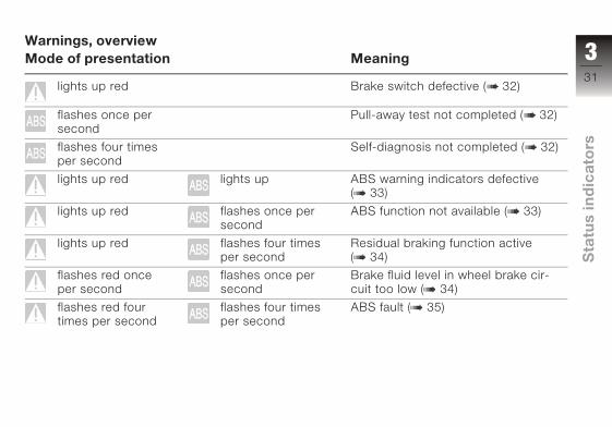
Warnings, overviewMode of presentation Meaning
lights up red Brake switch defective ( 32)
flashes once per
second
Pull-away test not completed ( 32)
flashes four times
per second
Self-diagnosis not completed ( 32)
lights up red lights up ABS warning indicators defective
( 33)
lights up red flashes once per
second
ABS function not available ( 33)
lights up red flashes four times
per second
Residual braking function active
( 34)
flashes red once
per second
flashes once per
second
Brake fluid level in wheel brake cir-
cuit too low ( 34)
flashes red four
times per second
flashes four times
per second
ABS fault ( 35)
331
z Sta
tus
ind
icat
ors
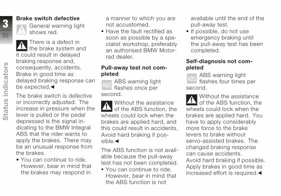
Brake switch defectiveGeneral warning light
shows red.
There is a defect in
the brake system and
it could result in delayed
braking response and,
consequently, accidents.
Brake in good time as
delayed braking response can
be expected.
The brake switch is defective
or incorrectly adjusted. The
increase in pressure when the
lever is pulled or the pedal
depressed is the signal in-
dicating to the BMW Integral
ABS that the rider wants to
apply the brakes. There may
be an unusual response from
the brakes.
You can continue to ride.
However, bear in mind that
the brakes may respond in
a manner to which you are
not accustomed.
Have the fault rectified as
soon as possible by a spe-
cialist workshop, preferably
an authorised BMW Motor-
rad dealer.
Pull-away test not com-pleted
ABS warning light
flashes once per
second.
Without the assistance
of the ABS function, the
wheels could lock when the
brakes are applied hard, and
this could result in accidents.
Avoid hard braking if pos-
sible.
The ABS function is not avail-
able because the pull-away
test has not been completed.
You can continue to ride.
However, bear in mind that
the ABS function is not
available until the end of the
pull-away test.
If possible, do not use
emergency braking until
the pull-away test has been
completed.
Self-diagnosis not com-pleted
ABS warning light
flashes four times per
second.
Without the assistance
of the ABS function, the
wheels could lock when the
brakes are applied hard. You
have to apply considerably
more force to the brake
levers to brake without
servo-assisted brakes. The
changed braking response
can cause accidents.
Avoid hard braking if possible.
Apply brakes in good time as
increased effort is required.
332
z Sta
tus
ind
icat
ors
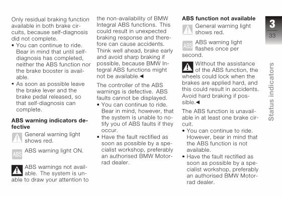
Only residual braking function
available in both brake cir-
cuits, because self-diagnosis
did not complete.
You can continue to ride.
Bear in mind that until self-
diagnosis has completed,
neither the ABS function nor
the brake booster is avail-
able.
As soon as possible leave
the brake lever and the
brake pedal released, so
that self-diagnosis can
complete.
ABS warning indicators de-fective
General warning light
shows red.
ABS warning light ON.
ABS warnings not avail-
able. The system is un-
able to draw your attention to
the non-availability of BMW
Integral ABS functions. This
could result in unexpected
braking response and there-
fore can cause accidents.
Think well ahead, brake early
and avoid sharp braking if
possible, because BMW In-
tegral ABS functions might
not be available.
The controller of the ABS
warnings is defective. ABS
faults cannot be displayed.
You can continue to ride.
Bear in mind, however, that
the system is unable to no-
tify you of ABS faults if they
occur.
Have the fault rectified as
soon as possible by a spe-
cialist workshop, preferably
an authorised BMW Motor-
rad dealer.
ABS function not availableGeneral warning light
shows red.
ABS warning light
flashes once per
second.
Without the assistance
of the ABS function, the
wheels could lock when the
brakes are applied hard, and
this could result in accidents.
Avoid hard braking if pos-
sible.
The ABS function is unavail-
able in at least one brake cir-
cuit.
You can continue to ride.
However, bear in mind that
the ABS function is not
available.
Have the fault rectified as
soon as possible by a spe-
cialist workshop, preferably
an authorised BMW Motor-
rad dealer.
333
z Sta
tus
ind
icat
ors
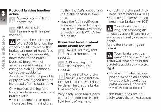
Residual braking functionactive
General warning light
shows red.
ABS warning light
flashes four times per
second.
Without the assistance
of the ABS function, the
wheels could lock when the
brakes are applied hard. You
have to apply considerably
more force to the brake
levers to brake without
servo-assisted brakes. The
changed braking response
can cause accidents.
Avoid hard braking if possible.
Apply brakes in good time as
increased effort is required.
Only residual braking func-
tion is available in at least one
brake circuit.
You can continue to ride.
However, bear in mind that
neither the ABS function nor
the brake booster is avail-
able.
Have the fault rectified as
soon as possible by a spe-
cialist workshop, preferably
an authorised BMW Motor-
rad dealer.
Brake fluid level in wheelbrake circuit too low
General warning light
flashes red once per
second.
ABS warning light
flashes once per
second.
The ABS wheel brake
circuit is a closed sys-
tem whose fluid level cannot
be determined at the brake
fluid reservoirs.
Very badly worn brake pads
can also trigger the "Brake
fluid too low" warning.
Checking brake-pad thick-
ness, front brakes ( 103)
Checking brake pad thick-
ness, rear brakes ( 104)
Worn brake pads can
lengthen stopping dis-
tances by a significant margin
and consequently cause acci-
dents.
Apply the brakes in good
time.
Worn brake pads can
damage the brake discs.
Think well ahead and brake
carefully; avoid severe brak-
ing.
Have worn brake pads re-
placed as soon as possible
by a specialist workshop,
preferably an authorised
BMW Motorrad dealer.
If the brake pads are not
badly worn, the brake system
334
z Sta
tus
ind
icat
ors
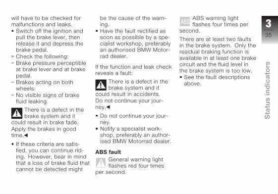
will have to be checked for
malfunctions and leaks.
Switch off the ignition and
pull the brake lever, then
release it and depress the
brake pedal.
Check the following:
Brake pressure perceptible
at brake lever and at brake
pedal.
Brakes acting on both
wheels.
No visible signs of brake
fluid leaking.
There is a defect in the
brake system and it
could result in brake fade.
Apply the brakes in good
time.
If these criteria are satis-
fied, you can continue rid-
ing. However, bear in mind
that a loss of brake fluid that
cannot be detected might
be the cause of the warn-
ing.
Have the fault rectified as
soon as possible by a spe-
cialist workshop, preferably
an authorised BMW Motor-
rad dealer.
If the function and leak check
reveals a fault:
There is a defect in the
brake system and it
could result in accidents.
Do not continue your jour-
ney.
Do not continue your jour-
ney.
Notify a specialist work-
shop, preferably an author-
ised BMW Motorrad dealer.
ABS faultGeneral warning light
flashes red four times
per second.
ABS warning light
flashes four times per
second.
There are at least two faults
in the brake system. Only the
residual braking function is
available in at least one brake
circuit and the fluid level in
the brake system is too low.
See the fault descriptions
above.
335
z Sta
tus
ind
icat
ors

336
z Sta
tus
ind
icat
ors

Operation
Ignition switch and steeringlock . . . . . . . . . . . . . . . . . . . . . . . . . . . 38
Electronic immobiliser (EWS) . . . 39
Hazard warning flashers . . . . . . . 40
Odometer and tripmeters . . . . . . 41
Clock . . . . . . . . . . . . . . . . . . . . . . . . . 42
Multifunction display . . . . . . . . . . . 42
On-board computerOE . . . . . . . . . 43
Cruise-control systemOE . . . . . . . 46
Emergency off switch (killswitch) . . . . . . . . . . . . . . . . . . . . . . . . 48
Grip heatingOE . . . . . . . . . . . . . . . . 49
Seat heatingOE . . . . . . . . . . . . . . . . 49
Clutch . . . . . . . . . . . . . . . . . . . . . . . . 51
Brakes . . . . . . . . . . . . . . . . . . . . . . . . 52
Lights . . . . . . . . . . . . . . . . . . . . . . . . . 52
Headlight . . . . . . . . . . . . . . . . . . . . . 54
Turn indicators . . . . . . . . . . . . . . . . 55
Stowage compartment. . . . . . . . . 56
Front and rear seats . . . . . . . . . . . 57
Helmet holder . . . . . . . . . . . . . . . . . 60
Mirrors . . . . . . . . . . . . . . . . . . . . . . . . 60
Windscreen . . . . . . . . . . . . . . . . . . . 61
Spring preload . . . . . . . . . . . . . . . . 61
Shock absorbers . . . . . . . . . . . . . . 62
Electronic SuspensionAdjustment ESAOE . . . . . . . . . . . . 63
Tyres . . . . . . . . . . . . . . . . . . . . . . . . . 65
437
z Op
era
tio
n
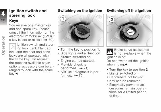
Ignition switch andsteering lockKeysYou receive one master key
and one spare key. Please
consult the information on the
electronic immobiliser (EWS) if
a key is lost or mislaid ( 39).
Ignition switch and steer-
ing lock, tank filler cap
lock and the seat and case
locks are all operated with
the same key. On request,
the topcase available as an
optional accessory can be ar-
ranged to lock with the same
key.
Switching on the ignition
Turn the key to position 1.
Side lights and all function
circuits switched on.
Engine can be started.
Pre-ride check is
performed. ( 71)
ABS self-diagnosis is per-
formed. ( 72)
Switching off the ignition
Brake servo assistance
is not available when the
ignition is off.
Do not switch off the ignition
when riding.
Turn the key to position 2.
Lights switched off.
Handlebars not locked.
Key can be removed.
Electrically powered ac-
cessories remain opera-
tional for a limited period
of time.
438
z Op
era
tio
n

The battery can be
recharged via the on-board
socket.
Locking the handlebars
If the motorcycle is on
the side stand, the sur-
face of the ground will de-
termine whether it is better to
turn the handlebars to the left
or right. However, the motor-
cycle is more stable on a level
surface with the handlebars
turned to the left than with
the handlebars turned to the
right.
On level ground, always turn
the handlebars to the left to
set the steering lock.
Turn the handlebars to the
full left or right lock position.
Turn the key to position 3,
while moving the handle-
bars slightly.
Ignition, lights and all func-
tion circuits switched off.
Handlebars locked.
Key can be removed.
Electronic immobiliser(EWS)Protection against theftThe electronic immobiliser
helps protect your BMW mo-
torcycle from theft, and this
enhanced security is at your
disposal without any need for
you to set parameters or ac-
tivate additional systems. The
engine of a motorcycle fitted
with this electronic immobil-
iser can be started only with
the keys that belong to the
vehicle. You can also have
your authorised BMW Mo-
torrad dealer bar individual
keys, for example if a partic-
ular key goes missing. The
engine cannot be started with
a key that has been barred.
In-key electronicsAn electronic component is
integrated into each of your
keys. The motorcycle's elec-
tronics exchange certain con-
tinuously changing signals
with the electronics in the
key; these signals are spe-
cific to your motorcycle and
they are transmitted via the
ring aerial in the ignition lock.
The ignition is not enabled for
starting until the key has been
recognised as "authorised" for
your motorcycle.
439
z Op
era
tio
n

A spare key attached
to the same ring as the
ignition key used to start the
engine could "irritate" the
electronics, in which case the
enabling signal for starting is
not issued. The EWS warning
appears in the multifunction
display.
Always keep the spare key
separately from the ignition
key.
Replacement keys andextra keysYou can obtain replace-
ment/extra keys only through
an authorised BMW Motorrad
dealer. The keys are part
of an integrated security
system, so the dealer is under
an obligation to check the
legitimacy of all applications
for replacement/extra keys. If
you want to have a lost key
barred, you have to bring with
you all the other keys that
belong to the motorcycle. A
key that has been barred can
subsequently be cleared and
reactivated for use.
Hazard warning flash-ersSwitching on the hazardwarning flashers
Switch on the ignition.
Simultaneously press but-
ton 1 for left turn indicators
and button 2 for right turn
indicators.
The hazard warning
flashers place a strain
on the battery. Do not use
the hazard warning flashers
for longer than absolutely
necessary.
If you press a turn-
indicator button with
the ignition switched on,
the turn-indicator function
is activated instead of the
hazard warning flashers,
and remains active until
you release the button. The
hazard warning flashers
recommence flashing as soon
as the button is released.
Hazard warning flashers in
operation.
Left/right turn indicator tell-
tale lights flash.
Switch off the ignition.
The hazard warning flashers
continue to operate.
440
z Op
era
tio
n

Left/right turn indicator tell-
tale lights off.
Switching off the hazardwarning flashers
Press cancel button 3.
Hazard warning flashers
switched off.
Alternative: Simultaneously
press button 1 for left turn
indicators and button 2 for
right turn indicators.
Hazard warning flashers
switched off.
Odometer and tripmet-ersOdometer
The odometer reading ap-
pears in display field 1.
Selecting the tripmeterSwitch on the ignition.
When you switch on the
ignition, the tripmeter
reading shown when the igni-
tion was switched off always
reappears on the multifunc-
tion display.
Briefly press tripmeter but-
ton 1 once to proceed to
each subsequent step in
the cycle.
The tripmeter display field al-
ternately shows the following:
Tripmeter 1 (Trip I)
441
z Op
era
tio
n

Tripmeter 2 (Trip II)
Tripmeter and on-boardcomputerOE
If your motorcycle is fitted
with an on-board computer,
the tripmeter readings in the
display field alternate with the
odometer reading.
Resetting the tripmeterSwitch on the ignition.
Select the desired tripmeter.
Press tripmeter button 1and hold it down for longer
than 2 seconds.
The tripmeter is reset to
zero.
ClockSetting the clock
Attempting to set the
clock while riding the
motorcycle can lead to ac-
cidents.
Set the clock only when the
motorcycle is stationary.
Switch on the ignition.
Press button 1 for longer
than 2 seconds.
Hours reading 2 starts to
flash.
Briefly press button 1.
The hour increments by one
each time you press the
button.
Press button 1 for longer
than 2 seconds.
Minutes reading 3 starts to
flash.
Briefly press button 1.
The minute increments by
one each time you press
the button.
Press button 1 for longer
than 2 seconds.
Setting confirmed.
Multifunction displayDisplay dimmingThe brightness of the backlit
multifunction display is vari-
able.
442
z Op
era
tio
n

Adjusting dimmer
Attempting to adjust the
dimmer while riding the
motorcycle can lead to acci-
dents.
Do not attempt to adjust the
dimmer unless the motorcycle
is at a standstill.
Press button 1.
The level of dimming ap-
pears in display field 2.
Press button 1 again.
The brightness of the
display increases one level
each time you press the
button. Each time you
press the button after
maximum brightness is
reached, brightness is
reduced by one level.
On-board computerOE
Selecting readings
Switch on the ignition.
Press BC button 1 briefly
each time.
The on-board computer's dis-
play field cycles through the
following sequence:
Residual range
Average speed
Average consumption
Oil level
Ambient temperature
Residual rangeResidual range is calculated
on the basis of your style of
riding and the amount of fuel
left in the tank; the reading
indicates the estimated dis-
tance you can travel before
the fuel supply runs out.
443
z Op
era
tio
n
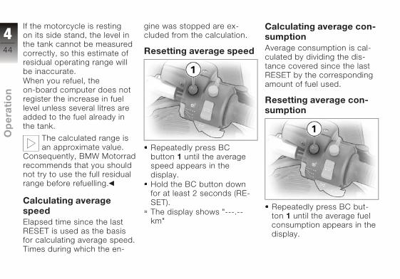
If the motorcycle is resting
on its side stand, the level in
the tank cannot be measured
correctly, so this estimate of
residual operating range will
be inaccurate.
When you refuel, the
on-board computer does not
register the increase in fuel
level unless several litres are
added to the fuel already in
the tank.
The calculated range is
an approximate value.
Consequently, BMW Motorrad
recommends that you should
not try to use the full residual
range before refuelling.
Calculating averagespeedElapsed time since the last
RESET is used as the basis
for calculating average speed.
Times during which the en-
gine was stopped are ex-
cluded from the calculation.
Resetting average speed
Repeatedly press BC
button 1 until the average
speed appears in the
display.
Hold the BC button down
for at least 2 seconds (RE-
SET).
The display shows "---.--
km"
Calculating average con-sumptionAverage consumption is cal-
culated by dividing the dis-
tance covered since the last
RESET by the corresponding
amount of fuel used.
Resetting average con-sumption
Repeatedly press BC but-
ton 1 until the average fuel
consumption appears in the
display.
444
z Op
era
tio
n
Hold the BC button down
for at least 2 seconds (RE-
SET).
The display shows
"--.- l/100 km".
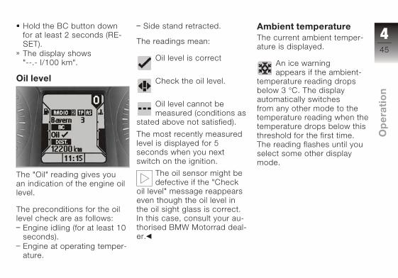
Oil level
The "Oil" reading gives you
an indication of the engine oil
level.
The preconditions for the oil
level check are as follows:
Engine idling (for at least 10
seconds).
Engine at operating temper-
ature.
Side stand retracted.
The readings mean:
Oil level is correct
Check the oil level.
Oil level cannot be
measured (conditions as
stated above not satisfied).
The most recently measured
level is displayed for 5
seconds when you next
switch on the ignition.
The oil sensor might be
defective if the "Check
oil level" message reappears
even though the oil level in
the oil sight glass is correct.
In this case, consult your au-
thorised BMW Motorrad deal-
er.
Ambient temperatureThe current ambient temper-
ature is displayed.
An ice warning
appears if the ambient-
temperature reading drops
below 3 °C. The display
automatically switches
from any other mode to the
temperature reading when the
temperature drops below this
threshold for the first time.
The reading flashes until you
select some other display
mode.
445
z Op
era
tio
n

Cruise-control sys-temOE
Switching on cruise con-trol
Move switch 1 to ON.
Telltale light 2 in the switch
lights up red.
Setting road speed
Briefly push button 3 in the
SET direction
Cruise control telltale
light shows.
The motorcycle maintains
your current cruising speed
and the setting is saved.
Step-by-step accelera-tion
Briefly push button 3 in the
SET direction
Speed is increased by ap-
prox. 2 km/h each time you
push the button, and the
new setting is saved.
446
z Op
era
tio
n
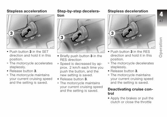
Stepless acceleration
Push button 3 in the SET
direction and hold it in this
position.
The motorcycle accelerates
steplessly.
Release button 3.
The motorcycle maintains
your current cruising speed
and the setting is saved.
Step-by-step decelera-tion
Briefly push button 3 in the
RES direction
Speed is decreased by ap-
prox. 2 km/h each time you
push the button, and the
new setting is saved.
Release button 3.
The motorcycle maintains
your current cruising speed
and the setting is saved.
Stepless deceleration
Push button 3 in the RES
direction and hold it in this
position.
The motorcycle decelerates
steplessly.
Release button 3.
The motorcycle maintains
your current cruising speed
and the setting is saved.
Deactivating cruise con-trol
Apply the brakes or pull the
clutch or close the throttle
447
z Op
era
tio
n

(turn the throttle twistgrip
back past the idle position).
The cruise-control system is
deactivated.
The cruise control telltale
light goes out.
The telltale light in the
switch remains on.
Resuming former cruis-ing speed
Push button 3 in the RES
direction.
Opening the throttle
does not deactivate
the cruise-control system. If
you release the twistgrip the
motorcycle will decelerate
only to the cruising speed
saved in memory, even
though you might have
intended slowing to a lower
speed.
Cruise control telltale
light shows.
The motorcycle resumes
the previous cruising speed.
Switching off cruise con-trol
Move switch 1 to OFF.
The system is deactivated.
Button 3 is locked.
Emergency off switch(kill switch)
1 Emergency off switch (kill
switch)
Operating the kill switch
when riding can cause
the rear wheel to lock and
thus cause a fall.
Do not operate the kill switch
when riding.
448
z Op
era
tio
n

The emergency off switch is a
kill switch for switching off the
engine quickly and easily.
A Normal operating posi-
tion (run)
B Engine switched off.
You cannot start the
engine unless the kill
switch is in the run position.
If you move the kill
switch away from the
RUN position while the
ignition is switched on, the
BMW Integral ABS remains
operational.
Grip heatingOE
1 Grip heating switch
The handlebar grips have
two-stage heating. Grip
heating can be activated only
when the engine is running.
The increase in power
consumption caused by
the grip heating can drain the
battery if you are riding at low
engine speeds. If the charge
level is low, grip heating is
switched off to ensure the
battery's starting capability.
2 Heating off.
3 50% heat output (one dot
visible)
4 100% heat output (three
dots visible)
Seat heatingOE
Dependency on batterycharge stateSeat heating can be activ-
ated only when the engine is
running. If the charge level is
low, the heating is switched
off to ensure the battery's
starting capability.
449
z Op
era
tio
n
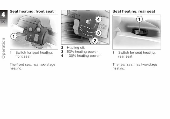
Seat heating, front seat
1 Switch for seat heating,
front seat
The front seat has two-stage
heating.
2 Heating off.
3 50% heating power
4 100% heating power
Seat heating, rear seat
1 Switch for seat heating,
rear seat
The rear seat has two-stage
heating.
450
z Op
era
tio
n
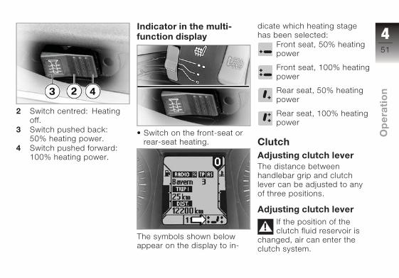
2 Switch centred: Heating
off.
3 Switch pushed back:
50% heating power.
4 Switch pushed forward:
100% heating power.
Indicator in the multi-function display
Switch on the front-seat or
rear-seat heating.
The symbols shown below
appear on the display to in-
dicate which heating stage
has been selected:
Front seat, 50% heating
power
Front seat, 100% heating
power
Rear seat, 50% heating
power
Rear seat, 100% heating
power
ClutchAdjusting clutch leverThe distance between
handlebar grip and clutch
lever can be adjusted to any
of three positions.
Adjusting clutch leverIf the position of the
clutch fluid reservoir is
changed, air can enter the
clutch system.
451
z Op
era
tio
n

Do not twist the handlebar
fitting or the handlebars.
Attempting to adjust the
clutch lever while riding
the motorcycle can lead to
accidents.
Do not attempt to adjust the
clutch lever unless the motor-
cycle is at a standstill.
Turn knob A to position 1:
smallest span.
Turn knob A to position 3:
largest span.
BrakesAdjusting handbrakeleverThe distance between
handlebar grip and handlebar
lever can be adjusted to any
of four positions.
Adjusting handbrakelever
Changing the position of
the brake-fluid reservoir
can allow air to penetrate the
brake system.
Do not twist the handlebar
fitting or the handlebars.
Attempting to adjust the
brake lever while riding
the motorcycle can lead to
accidents.
Do not attempt to adjust the
brake lever unless the motor-
cycle is at a standstill.
Turn knob B to position 1:
smallest span.
Turn knob B to position 4:
largest span.
LightsSwitching on the sidelightsThe side lights switch on
automatically when the
ignition is switched on.
The side lights place a
strain on the battery. Do
not switch the ignition on for
longer than absolutely neces-
sary.
452
z Op
era
tio
n
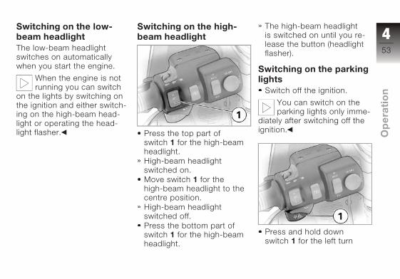
Switching on the low-beam headlightThe low-beam headlight
switches on automatically
when you start the engine.
When the engine is not
running you can switch
on the lights by switching on
the ignition and either switch-
ing on the high-beam head-
light or operating the head-
light flasher.
Switching on the high-beam headlight
Press the top part of
switch 1 for the high-beam
headlight.
High-beam headlight
switched on.
Move switch 1 for the
high-beam headlight to the
centre position.
High-beam headlight
switched off.
Press the bottom part of
switch 1 for the high-beam
headlight.
The high-beam headlight
is switched on until you re-
lease the button (headlight
flasher).
Switching on the parkinglights
Switch off the ignition.
You can switch on the
parking lights only imme-
diately after switching off the
ignition.
Press and hold down
switch 1 for the left turn
453
z Op
era
tio
n
indicators until the parking
lights are ON.
Switching off the parkinglights
Switch on the ignition.
Parking lights switched off.
HeadlightAdjusting headlight fordriving on left/driving onrightIf the motorcycle is ridden in
a country where the oppos-
ite rule of the road applies, its
asymmetric low-beam head-
light will tend to dazzle on-
coming traffic.
Have the headlight set
accordingly by a specialist
workshop, preferably an
authorised BMW Motorrad
dealer.
Commercially available
adhesive tape will dam-
age the plastic cover over the
light.
Use only the special, black
adhesive film for bodywork
applications available from
trade outlets.
Headlight beam throwand spring preloadHeadlight beam throw is gen-
erally kept constant when
spring preload is adjusted to
suit load.
Spring preload adjustment
might not suffice only if
the motorcycle is very
heavily loaded. Under these
circumstances, headlight
beam throw has to be
adjusted to suit the weight
carried by the motorcycle.
Consult a specialist
workshop, preferably
an authorised BMW Motor-
rad dealer, if you are unsure
whether the headlight basic
setting is correct.
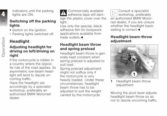
Headlight beam-throwadjustment
1 Headlight beam-throw
adjustment
Moving the pivot lever adjusts
headlight beam throw so as
not to dazzle oncoming traffic.
454
z Op
era
tio
n

A Position for heavy load
B Normal position
Turn indicatorsSwitching on the leftflashing turn indicators
Switch on the ignition.
Press left-hand turn indicat-
or button 1.
The turn indicators are
cancelled automatically
after you have ridden for ap-
proximately 10 seconds, or
covered a distance of about
200 m.
Left-hand turn indicator
switched on.
Telltale light for left-hand
turn indicator flashes.
Switching on the rightflashing turn indicators
Switch on the ignition.
Press right-hand turn indic-
ator button 2.
The turn indicators are
cancelled automatically
after you have ridden for ap-
proximately 10 seconds, or
covered a distance of about
200 m.
Right-hand turn indicator
switched on.
Telltale light for right-hand
turn indicator flashes.
455
z Op
era
tio
n

Cancelling the turn indic-ators
Press cancel button 3.
Flashing turn indicators
switched off.
Turn indicator telltale light is
off.
Stowage compart-mentStowage compartment inright side panelThe stowage compartment is
integrated into the right side
panel and opens with the igni-
tion key.
Opening the stowagecompartment
Use the ignition key to turn
lock barrel 1 to right angles
with the forward direction of
travel.
Lock of the stowage com-
partment unlocked.
Push the lock barrel in.
The lid opens.
Closing the stowagecompartment
Snap the lid of the com-
partment closed and push
it down.
The lock engages with an
audible click.
Use the ignition key to turn
the lock barrel in line with
the forward direction of
travel.
456
z Op
era
tio
n
Lock of the stowage com-
partment locked.
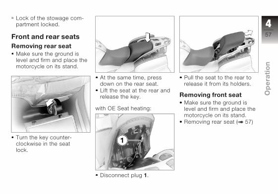
Front and rear seatsRemoving rear seat
Make sure the ground is
level and firm and place the
motorcycle on its stand.
Turn the key counter-
clockwise in the seat
lock.
At the same time, press
down on the rear seat.
Lift the seat at the rear and
release the key.
with OE Seat heating:
Disconnect plug 1.
Pull the seat to the rear to
release it from its holders.
Removing front seatMake sure the ground is
level and firm and place the
motorcycle on its stand.
Removing rear seat ( 57)
457
z Op
era
tio
n
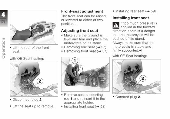
Lift the rear of the front
seat.
with OE Seat heating:
Disconnect plug 2.
Lift the seat up to remove.
Front-seat adjustmentThe front seat can be raised
or lowered to either of two
positions.
Adjusting front seatMake sure the ground is
level and firm and place the
motorcycle on its stand.
Removing rear seat ( 57)
Removing front seat ( 57)
Remove seat supporting
rod 1 and reinsert it in the
appropriate holder.
Installing front seat ( 58)
Installing rear seat ( 59)
Installing front seatIf too much pressure is
applied in the forward
direction, there is a danger
that the motorcycle will be
pushed off its stand.
Always make sure that the
motorcycle is stable and
firmly supported.
with OE Seat heating:
Connect plug 2.
458
z Op
era
tio
n

Push the front seat forward
into seat supporting
rod 1.Make sure that the
seat is correctly located.
If you install the seat in the
low position, check that the
seat's rubber buffers 3 en-
gage the bottom mounts in
the frame.
Firmly press the front seat
into the mount.
Installing rear seatIf too much pressure is
applied in the forward
direction, there is a danger
that the motorcycle will be
pushed off its stand.
Always make sure that the
motorcycle is stable and
firmly supported.
with OE Seat heating:
Connect plug 1.
Push the rear seat into the
holders in such a way that
the tongues engage the
corresponding holders.
459
z Op
era
tio
n

Press down firmly at the
rear of the seat.
The seat engages with an
audible click.
Helmet holderHelmet holder under-neath rear seat
Helmet holder 1 is on the rear
right, underneath the rear
seat.
Using helmet holderMake sure the ground is
level and firm and place the
motorcycle on its stand.
Removing rear seat ( 57)
The helmet catch can
scratch the panelling.
Make sure the lock is out of
the way when you hook the
helmet into position.
Use the wire rope available
as an optional extra to se-
cure the helmet to helmet
holder 1.
Installing rear seat ( 59)
MirrorsAdjusting mirrors
Move the mirror to the de-
sired position by pressing it
lightly at the corner.
460
z Op
era
tio
n

WindscreenAdjustable windscreen
The windscreen is steplessly
height-adjustable.
Adjusting windscreen
Switch on the ignition.
Press the top section of
button 1.
Windscreen higher
Press the bottom section of
button 1.
Windscreen lower
Spring preloadAdjusting spring preloadIt is essential to set spring
preload to suit the load
carried by the motorcycle.
Increase spring preload when
the motorcycle is heavily
loaded and reduce spring
preload accordingly when the
motorcycle is lightly loaded.
Adjusting spring preloadfor rear wheel
Your motorcycle's hand-
ling will suffer if you do
not match the spring-preload
and damping-characteristic
settings.
Adjust the damping char-
acteristic to suit spring pre-
load.
Adjusting spring preload
while the motorcycle is
being ridden can lead to acci-
dents.
Do not attempt to adjust
spring preload unless the
motorcycle is at a standstill.
Make sure the ground is
level and firm and place the
motorcycle on its stand.
If you want to increase
spring preload, turn knob 1
461
z Op
era
tio
n
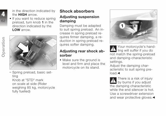
in the direction indicated by
the HIGH arrow.
If you want to reduce spring
preload, turn knob 1 in the
direction indicated by the
LOW arrow.
Spring preload, basic set-
ting
Knob at "STD" mark
on scale at side (Rider
weighing 85 kg, motorcycle
fully fuelled)
Shock absorbersAdjusting suspensiondampingDamping must be adapted
to suit spring preload. An in-
crease in spring preload re-
quires firmer damping, a re-
duction in spring preload re-
quires softer damping.
Adjusting rear shock ab-sorber
Make sure the ground is
level and firm and place the
motorcycle on its stand.
Your motorcycle's hand-
ling will suffer if you do
not match the spring-preload
and damping-characteristic
settings.
Adjust the damping char-
acteristic to suit spring pre-
load.
There is a risk of injury
by burns if you adjust
the damping characteristic
while the end silencer is hot.
Use a screwdriver extension
and wear protective gloves.
462
z Op
era
tio
n
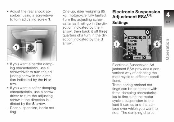
Adjust the rear shock ab-
sorber, using a screwdriver
to turn adjusting screw 1.
If you want a harder damp-
ing characteristic, use a
screwdriver to turn the ad-
justing screw in the direc-
tion indicated by the H ar-
row.
If you want a softer damping
characteristic, use a screw-
driver to turn the adjusting
screw in the direction in-
dicted by the S arrow.
Rear suspension, basic set-
ting
One-up, rider weighing 85
kg, motorcycle fully fuelled.
Turn the adjusting screw
as far as it will go in the dir-
ection indicated by the H
arrow, then back it off three
quarters of a turn in the dir-
ection indicated by the S
arrow.
Electronic SuspensionAdjustment ESAOE
Settings
Electronic Suspension Ad-
justment ESA provides a con-
venient way of adapting the
motorcycle to different condi-
tions.
Three spring preload set-
tings can be combined with
three damping characterist-
ics to fine-tune the motor-
cycle's suspension to the
load it carries and the sur-
face over which you want to
ride. The damping charac-
463
z Op
era
tio
n

teristic is shown in panel 1 of
the multifunction display, and
spring preload in panel 2. The
Tripmaster readings are not
shown while the ESA readout
is active.
Calling up settingsSwitch on the ignition.
Briefly press button 1.
The current setting is dis-
played.
The reading remains visible
for a few seconds before
disappearing automatically.
Adjusting suspensiondamping
Switch on the ignition.
Briefly press button 1.
The current setting is dis-
played.
Press button 1 once briefly.
The display field starts
at the current status and
cycles through the following
sequence:
Comfortable damping
characteristic
Normal damping charac-
teristic
Sporty damping charac-
teristic
The setting shown on the
display is automatically
accepted as the damping
characteristic if you allow
a certain length off time
to pass without pressing
button 1.During the setting
procedure, the display
flashes.
You can adjust the
damping characteristic
while the motorcycle is on the
move.
Adjusting spring preloadStart the engine.
464
z Op
era
tio
n
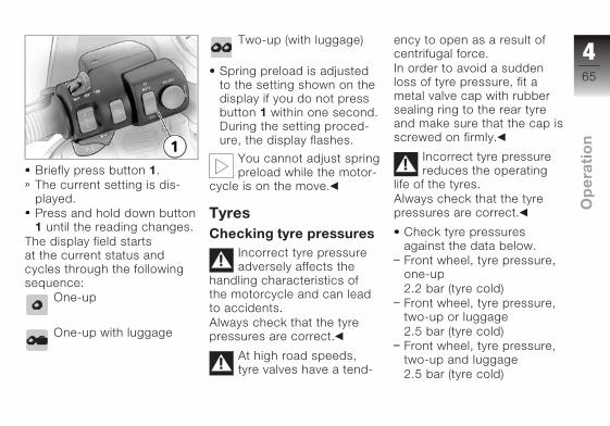
Briefly press button 1.
The current setting is dis-
played.
Press and hold down button
1 until the reading changes.
The display field starts
at the current status and
cycles through the following
sequence:
One-up
One-up with luggage
Two-up (with luggage)
Spring preload is adjusted
to the setting shown on the
display if you do not press
button 1 within one second.
During the setting proced-
ure, the display flashes.
You cannot adjust spring
preload while the motor-
cycle is on the move.
TyresChecking tyre pressures
Incorrect tyre pressure
adversely affects the
handling characteristics of
the motorcycle and can lead
to accidents.
Always check that the tyre
pressures are correct.
At high road speeds,
tyre valves have a tend-
ency to open as a result of
centrifugal force.
In order to avoid a sudden
loss of tyre pressure, fit a
metal valve cap with rubber
sealing ring to the rear tyre
and make sure that the cap is
screwed on firmly.
Incorrect tyre pressure
reduces the operating
life of the tyres.
Always check that the tyre
pressures are correct.
Check tyre pressures
against the data below.
Front wheel, tyre pressure,
one-up
2.2 bar (tyre cold)
Front wheel, tyre pressure,
two-up or luggage
2.5 bar (tyre cold)
Front wheel, tyre pressure,
two-up and luggage
2.5 bar (tyre cold)
465
z Op
era
tio
n
Rear wheel, tyre pressure,
one-up
2.5 bar (tyre cold)
Rear wheel, tyre pressure,
two-up or luggage
2.9 bar (tyre cold)
Rear wheel, tyre pressure,
two-up and luggage
2.9 bar (tyre cold)
If tyre pressure is too low:
Correct tyre pressure.
466
z Op
era
tio
n
Riding
Safety instructions . . . . . . . . . . . . . 68
Checklist . . . . . . . . . . . . . . . . . . . . . . 70
Starting . . . . . . . . . . . . . . . . . . . . . . . 70
Pulling away . . . . . . . . . . . . . . . . . . 72
Running in . . . . . . . . . . . . . . . . . . . . 73
Parking your motorcycle . . . . . . . 77
Refuelling . . . . . . . . . . . . . . . . . . . . . 84
Brake system, general . . . . . . . . . 85
Brake system with BMW IntegralABS . . . . . . . . . . . . . . . . . . . . . . . . . . 86
567
z Rid
ing

Safety instructionsRider's equipmentDo not ride without the cor-
rect clothing. Always wear:
helmet
motorcycling jacket and
trousers
gloves
boots
This applies even to short
journeys, and to every sea-
son of the year. Your author-
ised BMW Motorrad dealer
will be glad to advise you on
the correct clothing for every
purpose.
SpeedIf you ride at high speed, al-
ways bear in mind that vari-
ous boundary conditions can
adversely affect the handling
of your motorcycle:
settings of the spring-strut
and shock-absorber system
imbalanced load
loose clothing
insufficient tyre pressure
poor tyre tread
etc.
Correct loadingOverloading and
imbalanced loads
can adversely affect the
motorcycle's handling.
Do not exceed the permiss-
ible gross weight and be sure
to comply with the instruc-
tions on loading.
Alcohol and drugsEven small amounts of
alcohol or drugs will ad-
versely affect your percep-
tion and your ability to as-
sess situations and make de-
cisions, and slow down your
reflexes. Medication can ex-
acerbate these effects.
Do not ride your motorcycle
after consuming alcohol,
drugs and/or medication.
Risk of poisoningExhaust fumes contain car-
bon monoxide, which is col-
ourless and odourless but
highly toxic.
Inhaling the exhaust
fumes therefore
represents a health hazard
and can even cause loss
of consciousness with fatal
consequences.
Do not inhale exhaust fumes.
Do not run the engine in an
enclosed space.
568
z Rid
ing
High voltageTouching live parts of
the ignition system with
the engine running can cause
electric shock.
Do not touch parts of the igni-
tion system when the engine
is running.
Catalytic converterIf misfiring causes unburned
fuel to enter the catalytic con-
verter, there is a danger of
overheating and damage.
For this reason, observe the
following points:
Do not run the fuel tank dry.
Do not attempt to start or
run the engine with a spark-
plug cap disconnected.
Stop the engine immediately
if it misfires.
Use only unleaded fuel.
Comply with all specified
maintenance intervals.
Unburned fuel will des-
troy the catalytic con-
verter.
Note the points listed for pro-
tection of the catalytic con-
verter.
Risk of fireTemperatures at the exhaust
are high.
Flammable materials
(e.g. hay, leaves, grass,
clothing and luggage, etc.)
could ignite if allowed to
come into contact with the
hot exhaust pipe.
Do not permit flammable ma-
terials to come into contact
with the hot exhaust system.
Cooling would be
inadequate if the engine
were allowed to idle for
a lengthy period with the
motorcycle at a standstill:
overheating would result.
In extreme cases, the
motorcycle could catch fire.
Do not allow the engine to
idle unnecessarily. Ride away
immediately after starting the
engine.
Tampering with the con-trol unit of the electronicengine-management sys-tem
Tampering with the con-
trol unit of the electronic
engine-management system
can damage the motorcycle
and cause accidents.
Do not tamper with the
control unit of the electronic
engine-management
system.
Tampering with the con-
trol unit of the electron-
ic engine-management sys-
tem can result in mechanical
loads that the motorcycle's
569
z Rid
ing

components are not designed
to withstand. Damage caused
in this way is not covered by
the warranty.
Do not tamper with the
control unit of the electronic
engine-management
system.
ChecklistUse the following checklist
to check important functions,
settings and wear limits be-
fore you ride off.
Brakes
Brake-fluid levels, front and
rear
Clutch
Clutch fluid level
Shock absorber setting and
spring preload
Tyre-tread depth and tyre
pressures
Cases correctly installed
and luggage secured
At regular intervals:
Engine oil level (every refuel-
ling stop)
Brake-pad wear (every third
refuelling stop)
StartingSide standYou cannot start the motor-
cycle with the side stand ex-
tended and a gear engaged.
The engine will switch itself
off if you start it with the gear-
box in neutral and then en-
gage a gear before retracting
the side stand.
GearboxYou can start the engine
when the gearbox is in neutral
or if you pull the clutch with a
gear engaged. Switch on the
ignition before you pull the
clutch. When the gearbox is
in neutral, the green neutral
telltale light is on and the gear
indicator in the multifunction
display shows 0.
Starting the engine
If you switch on the ig-
nition while the brakes
are applied, then start the
engine and ride off immedi-
ately, the BMW Integral ABS
remains in residual braking
function mode. Self-diagnosis
is performed as soon as the
brake levers are in their fully
released positions for the first
570
z Rid
ing
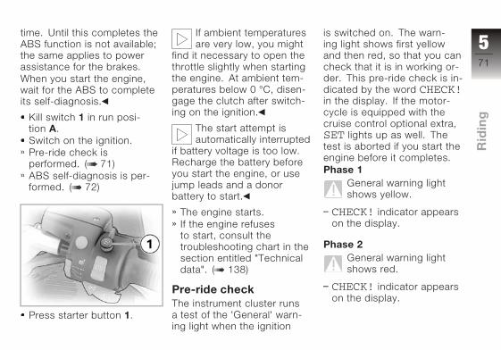
time. Until this completes the
ABS function is not available;
the same applies to power
assistance for the brakes.
When you start the engine,
wait for the ABS to complete
its self-diagnosis.
Kill switch 1 in run posi-
tion A.
Switch on the ignition.
Pre-ride check is
performed. ( 71)
ABS self-diagnosis is per-
formed. ( 72)
Press starter button 1.
If ambient temperatures
are very low, you might
find it necessary to open the
throttle slightly when starting
the engine. At ambient tem-
peratures below 0 °C, disen-
gage the clutch after switch-
ing on the ignition.
The start attempt is
automatically interrupted
if battery voltage is too low.
Recharge the battery before
you start the engine, or use
jump leads and a donor
battery to start.
The engine starts.
If the engine refuses
to start, consult the
troubleshooting chart in the
section entitled "Technical
data". ( 138)
Pre-ride checkThe instrument cluster runs
a test of the 'General' warn-
ing light when the ignition
is switched on. The warn-
ing light shows first yellow
and then red, so that you can
check that it is in working or-
der. This pre-ride check is in-
dicated by the word CHECK!in the display. If the motor-
cycle is equipped with the
cruise control optional extra,
SET lights up as well. The
test is aborted if you start the
engine before it completes.
Phase 1General warning light
shows yellow.
CHECK! indicator appears
on the display.
Phase 2General warning light
shows red.
CHECK! indicator appears
on the display.
571
z Rid
ing

If the motorcycle is fitted
with the cruise-control
optional extra, the cruise con-
trol telltale light shows.
If the 'General' warning light is
not displayed:
Some malfunctions can-
not be indicated if the
'General' warning light cannot
be displayed.
Check that the 'General'
warning light comes on, and
that it lights up yellow and
then red.
Have the fault rectified as
soon as possible by a spe-
cialist workshop, preferably
an authorised BMW Motor-
rad dealer.
ABS self-diagnosisBMW Integral ABS performs
self-diagnosis and a
pull-away test to ensure its
operability. Self-diagnosis
is performed automatically
when you switch on the
ignition. Self-diagnosis is
not performed unless both
brake levers are in their fully
released positions.
Phase 1Self-diagnosis is in progress.
General warning light
shows red.
ABS warning light
flashes four times per
second.
Phase 2Self-diagnosis is complete.
ABS warning light
flashes once per
second.
If self-diagnosis did not com-
plete:
Release the brake levers as
soon as possible.
If an error message appears
when self-diagnosis com-
pletes:
See the section entitled
"Status indicators" for in-
formation on how to inter-
pret these messages.
The ABS warning light
does not go out until the
pull-away test completes.
Pulling awayStarting on gradients
Select a gear.
Release the clutch lever and
the brake levers.
Switch on the ignition.
Wait for ABS self-diagnosis
to complete.
Apply the brakes and disen-
gage the clutch.
Start the engine.
572
z Rid
ing
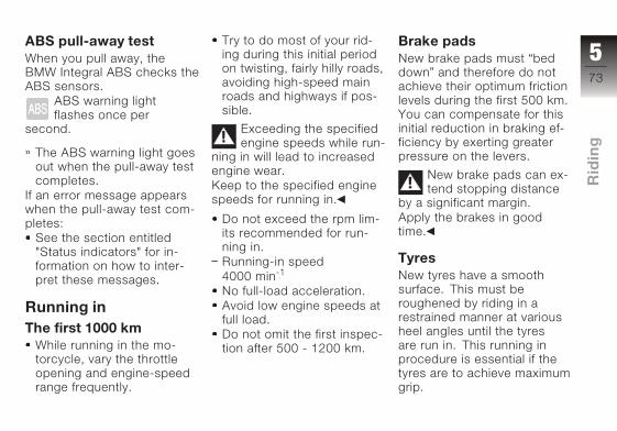
ABS pull-away testWhen you pull away, the
BMW Integral ABS checks the
ABS sensors.
ABS warning light
flashes once per
second.
The ABS warning light goes
out when the pull-away test
completes.
If an error message appears
when the pull-away test com-
pletes:
See the section entitled
"Status indicators" for in-
formation on how to inter-
pret these messages.
Running inThe first 1000 km
While running in the mo-
torcycle, vary the throttle
opening and engine-speed
range frequently.
Try to do most of your rid-
ing during this initial period
on twisting, fairly hilly roads,
avoiding high-speed main
roads and highways if pos-
sible.
Exceeding the specified
engine speeds while run-
ning in will lead to increased
engine wear.
Keep to the specified engine
speeds for running in.
Do not exceed the rpm lim-
its recommended for run-
ning in.
Running-in speed
4000 min-1
No full-load acceleration.
Avoid low engine speeds at
full load.
Do not omit the first inspec-
tion after 500 - 1200 km.
Brake padsNew brake pads must “bed
down” and therefore do not
achieve their optimum friction
levels during the first 500 km.
You can compensate for this
initial reduction in braking ef-
ficiency by exerting greater
pressure on the levers.
New brake pads can ex-
tend stopping distance
by a significant margin.
Apply the brakes in good
time.
TyresNew tyres have a smooth
surface. This must be
roughened by riding in a
restrained manner at various
heel angles until the tyres
are run in. This running in
procedure is essential if the
tyres are to achieve maximum
grip.
573
z Rid
ing

Tyres do not have their
full grip when new and
there is a risk of accident at
extreme angles of heel.
Avoid extreme angles of
heel.
574
z Rid
ing

575
z Rid
ing

576
z Rid
ing
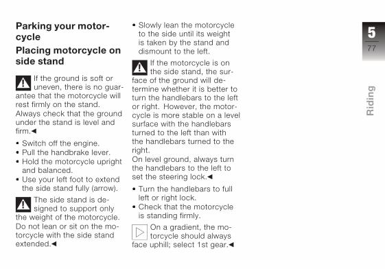
Parking your motor-cyclePlacing motorcycle onside stand
If the ground is soft or
uneven, there is no guar-
antee that the motorcycle will
rest firmly on the stand.
Always check that the ground
under the stand is level and
firm.
Switch off the engine.
Pull the handbrake lever.
Hold the motorcycle upright
and balanced.
Use your left foot to extend
the side stand fully (arrow).
The side stand is de-
signed to support only
the weight of the motorcycle.
Do not lean or sit on the mo-
torcycle with the side stand
extended.
Slowly lean the motorcycle
to the side until its weight
is taken by the stand and
dismount to the left.
If the motorcycle is on
the side stand, the sur-
face of the ground will de-
termine whether it is better to
turn the handlebars to the left
or right. However, the motor-
cycle is more stable on a level
surface with the handlebars
turned to the left than with
the handlebars turned to the
right.
On level ground, always turn
the handlebars to the left to
set the steering lock.
Turn the handlebars to full
left or right lock.
Check that the motorcycle
is standing firmly.
On a gradient, the mo-
torcycle should always
face uphill; select 1st gear.
577
z Rid
ing

578
z Rid
ing
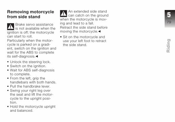
Removing motorcyclefrom side stand
Brake servo assistance
is not available when the
ignition is off; the motorcycle
can start to roll.
Particularly when the motor-
cycle is parked on a gradi-
ent, switch on the ignition and
wait for the ABS to complete
its self-diagnosis.
Unlock the steering lock.
Switch on the ignition.
Wait for ABS self-diagnosis
to complete.
From the left, grip the
handlebars with both hands.
Pull the handbrake lever.
Swing your right leg over
the seat and lift the motor-
cycle to the upright posi-
tion.
Hold the motorcycle upright
and balanced.
An extended side stand
can catch on the ground
when the motorcycle is mov-
ing and lead to a fall.
Retract the side stand before
moving the motorcycle.
Sit on the motorcycle and
use your left foot to retract
the side stand.
579
z Rid
ing

580
z Rid
ing
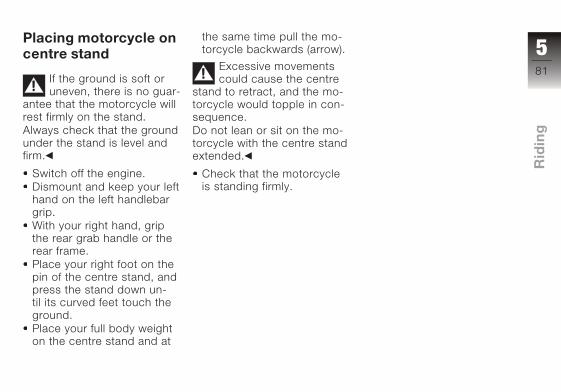
Placing motorcycle oncentre stand
If the ground is soft or
uneven, there is no guar-
antee that the motorcycle will
rest firmly on the stand.
Always check that the ground
under the stand is level and
firm.
Switch off the engine.
Dismount and keep your left
hand on the left handlebar
grip.
With your right hand, grip
the rear grab handle or the
rear frame.
Place your right foot on the
pin of the centre stand, and
press the stand down un-
til its curved feet touch the
ground.
Place your full body weight
on the centre stand and at
the same time pull the mo-
torcycle backwards (arrow).
Excessive movements
could cause the centre
stand to retract, and the mo-
torcycle would topple in con-
sequence.
Do not lean or sit on the mo-
torcycle with the centre stand
extended.
Check that the motorcycle
is standing firmly.
581
z Rid
ing
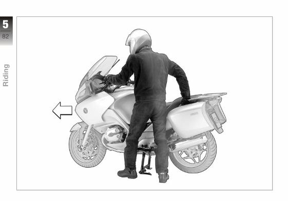
582
z Rid
ing
Removing motorcyclefrom centre stand
Brake servo assistance
is not available when the
ignition is off; the motorcycle
can start to roll.
Particularly when the motor-
cycle is parked on a gradi-
ent, switch on the ignition and
wait for the ABS to complete
its self-diagnosis.
Switch on the ignition.
Wait for ABS self-diagnosis
to complete.
Place your left hand on the
left handlebar grip.
Grip the rear grab handle
with your right hand.
Push the motorcycle for-
ward off the centre stand.
Check that the centre stand
has fully retracted.
583
z Rid
ing

RefuellingFuel is highly flammable.
A naked flame close to
the fuel tank can cause a fire
or explosion.
Do not smoke. Never bring
a naked flame near the fuel
tank.
Fuel expands when hot.
Fuel escaping from an
overfilled tank could make its
way onto the rear tyre. This
could cause a fall.
Do not fill the tank past the
bottom edge of the filler
neck.
Fuel attacks plastics,
which become dull or
unsightly.
Wipe off plastic parts immedi-
ately if they come into contact
with fuel.
Leaded fuel will destroy
the catalytic converter.
Use only unleaded fuel.
Make sure the ground is
level and firm and place the
motorcycle on its stand.
Open the protective cap.
Open the fuel tank cap with
the ignition key by turning it
counter-clockwise.
Refuel with fuel of the grade
stated below.
The ratings for perform-
ance and consumption
are quoted for the recommen-
ded grade of fuel.
Recommended fuel grade
Super Plus (premium), un-
leaded
98 ROZ
Fuel grade, usable with
power- and consumption-
related restrictions
Regular, unleaded
91 ROZ
Usable fuel capacity
27 l
Reserve fuel
4 l
584
z Rid
ing
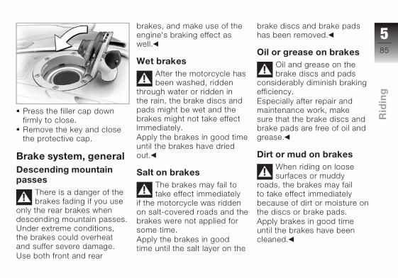
Press the filler cap down
firmly to close.
Remove the key and close
the protective cap.
Brake system, generalDescending mountainpasses
There is a danger of the
brakes fading if you use
only the rear brakes when
descending mountain passes.
Under extreme conditions,
the brakes could overheat
and suffer severe damage.
Use both front and rear
brakes, and make use of the
engine's braking effect as
well.
Wet brakesAfter the motorcycle has
been washed, ridden
through water or ridden in
the rain, the brake discs and
pads might be wet and the
brakes might not take effect
immediately.
Apply the brakes in good time
until the brakes have dried
out.
Salt on brakesThe brakes may fail to
take effect immediately
if the motorcycle was ridden
on salt-covered roads and the
brakes were not applied for
some time.
Apply the brakes in good
time until the salt layer on the
brake discs and brake pads
has been removed.
Oil or grease on brakesOil and grease on the
brake discs and pads
considerably diminish braking
efficiency.
Especially after repair and
maintenance work, make
sure that the brake discs and
brake pads are free of oil and
grease.
Dirt or mud on brakesWhen riding on loose
surfaces or muddy
roads, the brakes may fail
to take effect immediately
because of dirt or moisture on
the discs or brake pads.
Apply brakes in good time
until the brakes have been
cleaned.
585
z Rid
ing
The brake pads will wear
more rapidly if you ride
frequently on unsurfaced
tracks or poor roads.
Check the thickness of the
brake pads more frequently
and replace the brake pads in
good time.
Brake system withBMW Integral ABSSensitive electronic con-trolIt takes skill and sensitive
control of the brakes to pull
up safely on a motorcycle. If
the front brakes lock and the
wheel skids, the necessary
longitudinal and lateral stabil-
ising forces are lost, and a fall
can result. For this reason,
the rider seldom makes full
use of available braking per-
formance in an emergency.
BMW Integral ABS provides
improved braking deceler-
ation by means of anti-lock
braking for both wheels and
braking force distribution by
means of the integral brak-
ing function. Making full use
of the motorcycle's technical
braking capacity will minimise
braking distances noticeably,
even when road conditions
are poor. When the motor-
cycle is ravelling in a straight
line, BMW Integral ABS en-
ables safe optimised emer-
gency braking adapted to
match the road-surface con-
ditions.
Reserves for safetyThe potentially shorter brak-
ing distances which BMW
Integral ABS permits must
not be used as an excuse
for careless riding. ABS is
primarily a means of ensur-
ing a safety margin in genuine
emergencies.
Take care when cornering.
When you apply the brakes
on a corner, the motorcycle's
weight and momentum take
over and even BMW Integral
ABS is unable to counteract
their effects.
Partially integral brakesYour motorcycle is equipped
with partially integral brakes.
Both front and rear brakes
are applied when you pull the
handbrake lever. The foot-
brake lever acts only on the
rear brake.
The electronic controller in
the BMW Integral ABS regu-
lates braking-force distribu-
tion between front and rear
wheels. Braking-force distri-
bution depends on load and
is recalculated every time the
586
z Rid
ing

ABS controller comes into ac-
tion.
Brake boosterThe hydraulic pump in the
BMW Integral ABS boosts
the braking force acting on
the wheel when the brakes
are applied. By boosting the
braking force in this way,
BMW Integral ABS achieves
higher braking efficiency than
standard brake systems.
ABS anti-lock brakingsystemABS prevents the wheels
locking under braking, thus
contributing significantly to
road safety.
Rear wheel liftEven under severe braking,
a high level of tyre grip can
mean that the front wheel
does not lock up until very
late, if at all. Consequently,
ABS does not intervene until
very late, if at all. Under these
circumstances the rear wheel
can lift off the ground, and the
outcome can be a highsiding
situation in which the motor-
cycle can flip over.
Severe braking can
cause the rear wheel to
lift off the ground.
Bear in mind that ABS can-
not be relied on in all circum-
stances to prevent the rear
wheel from lifting clear of the
ground.
Residual braking func-tionWhen the ignition is switched
off, during self-diagnosis,
or if the BMW Integral ABS
malfunctions, only a residual
braking function remains
available in the brake circuits
in question. The residual
braking function is the braking
power without the hydraulic
servo assistance of the BMW
Integral ABS. Under these
circumstances, therefore,
you must apply considerably
higher pressure to the brake
levers in question in order to
apply the brakes, and lever
travel is longer. When the
residual braking function
is active, the ABS function
is unavailable in the brake
system in question. When the
residual braking function is
active, the integral braking
function is partially or entirely
unavailable.
Without the assistance
of the ABS function, the
wheels could lock when the
brakes are applied hard. You
have to apply considerably
more force to the brake
levers to brake without
servo-assisted brakes. The
587
z Rid
ing
changed braking response
can cause accidents.
Avoid hard braking if possible.
Apply brakes in good time as
increased effort is required.
Have the fault rectified as
soon as possible by a spe-
cialist workshop, preferably
an authorised BMW Motorrad
dealer.
The brake-lever travel
needed to build up brak-
ing pressure can be consider-
ably longer when the system
is in residual braking function
mode, so BMW Motorrad re-
commends setting the brake
lever to a wider span.
When the residual brak-
ing function is active for
both brake circuits, the noise
of the pump is no longer aud-
ible when you operate the
brake levers.
588
z Rid
ing

Accessories
General instructions . . . . . . . . . . . 90
Power socket . . . . . . . . . . . . . . . . . 90
Luggage . . . . . . . . . . . . . . . . . . . . . . 93
Case . . . . . . . . . . . . . . . . . . . . . . . . . . 94
TopcaseOA . . . . . . . . . . . . . . . . . . . . 96
689
z Ac
ce
sso
rie
s

General instructionsBMW Motorrad recommends
the use of parts and ac-
cessories for your motorcycle
that are approved by BMW for
this purpose.
Genuine BMW parts and ac-
cessories and other products
which BMW has approved
can be obtained from your
authorised BMW Motorrad
dealer, together with expert
advice on their installation
and use.
These parts and products
have been tested by BMW for
safety, function and suitability.
BMW accepts product liability
for them.
Conversely, BMW is unable
to accept any liability whatso-
ever for parts and accessor-
ies which it has not approved.
BMW cannot examine
or test each product of
outside origin to ensure that it
can be used on or in connec-
tion with BMW motorcycles
without constituting a safety
hazard. Country-specific of-
ficial authorisation does not
suffice as assurance. Tests
conducted by these instances
cannot make provision for all
operating conditions experi-
enced by BMW motorcycles
and, consequently, they are
not sufficient in some circum-
stances.
Use only parts and accessor-
ies approved by BMW for
your motorcycle.
Whenever you are planning
modifications, comply with all
the legal requirements. Make
sure that the motorcycle does
not infringe national road-
vehicle construction and use
regulations.
Power socketRatingsThe supply to the socket is
cut off automatically if battery
voltage is low or if the load
exceeds 5 A.
On-board socket, front left
690
z Ac
ce
sso
rie
s

On-board socket, rear left
Operating electrical ac-cessoriesYou can start using electrical
accessories only when the ig-
nition is switched on. The ac-
cessory remains operational
if the ignition is subsequently
switched off. In order to en-
sure that the drain on the on-
board power supply system is
minimised, the supply to the
power socket is cut off ap-
proximately 15 minutes after
the ignition is switched off,
and it is also temporarily in-
terrupted during the start pro-
cedure.
Cable routingThe cables from the power
socket to the auxiliary device
must be routed in such a way
that they:
do not impede the rider
do not restrict or obstruct
the steering angle and
handling characteristics
cannot be trapped
Incorrectly routed cables
can impede the rider.
Route the cables as
described above.
691
z Ac
ce
sso
rie
s

692
z Ac
ce
sso
rie
s

LuggageCorrect loading
Overloading and
imbalanced loads
can adversely affect the
motorcycle's handling.
Do not exceed the permiss-
ible gross weight and be sure
to comply with the instruc-
tions on loading.
Fitting a luggage system will
affect the handling of your
motorcycle. The maximum
speed recommended for
riding with loaded cases is
180 km/h. If the large or small
topcase available is fitted, the
maximum permissible speed
is 180 km/h.
Set spring preload, damping
characteristic and tyre pres-
sures to suit total weight.
Make sure that the weight
is uniformly distributed
between right and left.
Pack heavy items at the
bottom and toward the in-
board side.
Max. load in each case (left
and right): 10 kg.
Max. load in tank rucksack
5 kg.
693
z Ac
ce
sso
rie
s

CaseOpening cases
Turn the lock with the key
until it is transverse to the
forward direction of travel.
The case is unlocked.
Press lock barrel 1.
Lever 2 pops up.
Pivot lever 2 down.
Open the lid.
Closing cases
Pull lever 2 back as far as it
will go.
Close lid 3 and press it
down. Check that nothing is
trapped between the lid and
the case.
694
z Ac
ce
sso
rie
s

Push the lever down.
The lever engages.
Turn the lock with the key
until it is in line with the for-
ward direction of travel.
The case is closed.
Removing the case
Turn the lock with the key
until it is transverse to the
forward direction of travel.
The case is unlocked.
Turn the key clockwise (left
case) or counter-clockwise
(right case).
Handle 4 pops out.
Pull the handle out and then
pull it up as far as it will go.
695
z Ac
ce
sso
rie
s
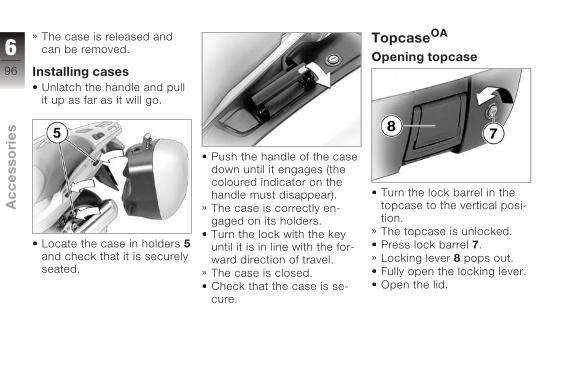
The case is released and
can be removed.
Installing casesUnlatch the handle and pull
it up as far as it will go.
Locate the case in holders 5and check that it is securely
seated.
Push the handle of the case
down until it engages (the
coloured indicator on the
handle must disappear).
The case is correctly en-
gaged on its holders.
Turn the lock with the key
until it is in line with the for-
ward direction of travel.
The case is closed.
Check that the case is se-
cure.
TopcaseOA
Opening topcase
Turn the lock barrel in the
topcase to the vertical posi-
tion.
The topcase is unlocked.
Press lock barrel 7.
Locking lever 8 pops out.
Fully open the locking lever.
Open the lid.
696
z Ac
ce
sso
rie
s
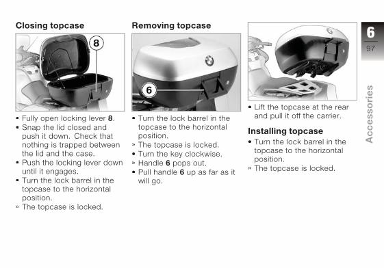
Closing topcase
Fully open locking lever 8.
Snap the lid closed and
push it down. Check that
nothing is trapped between
the lid and the case.
Push the locking lever down
until it engages.
Turn the lock barrel in the
topcase to the horizontal
position.
The topcase is locked.
Removing topcase
Turn the lock barrel in the
topcase to the horizontal
position.
The topcase is locked.
Turn the key clockwise.
Handle 6 pops out.
Pull handle 6 up as far as it
will go.
Lift the topcase at the rear
and pull it off the carrier.
Installing topcaseTurn the lock barrel in the
topcase to the horizontal
position.
The topcase is locked.
697
z Ac
ce
sso
rie
s

Turn the key clockwise.
Handle 6 pops out.
Pull handle 6 up as far as it
will go.
Hook the topcase into po-
sition on the carrier. Make
sure that hooks 7 are se-
curely seated in the corres-
ponding keepers 8.
Push the handle down until
it engages (the coloured in-
dicator on the handle must
disappear).
The topcase is correctly en-
gaged on its carrier.
698
z Ac
ce
sso
rie
s
Maintenance
General instructions . . . . . . . . . . 100
Toolkit . . . . . . . . . . . . . . . . . . . . . . . 100
Overview, toolkit . . . . . . . . . . . . . 100
Supplementary kitOA . . . . . . . . . . 100
Overview, supplementarykit . . . . . . . . . . . . . . . . . . . . . . . . . . . 101
Engine oil . . . . . . . . . . . . . . . . . . . . 101
Brake system, general . . . . . . . . 102
Brake pads. . . . . . . . . . . . . . . . . . . 103
Brake fluid . . . . . . . . . . . . . . . . . . . 105
Clutch . . . . . . . . . . . . . . . . . . . . . . . 107
Tyres . . . . . . . . . . . . . . . . . . . . . . . . 107
Rims . . . . . . . . . . . . . . . . . . . . . . . . . 108
Wheels . . . . . . . . . . . . . . . . . . . . . . 108
Front wheel stand . . . . . . . . . . . . 114
Bulbs . . . . . . . . . . . . . . . . . . . . . . . . 116
Jump starting . . . . . . . . . . . . . . . . 125
Battery . . . . . . . . . . . . . . . . . . . . . . . 126
799
z Mai
nte
nan
ce

General instructionsThe Maintenance chapter de-
scribes straightforward pro-
cedures for checking and re-
placing certain wear parts.
Special tightening torques
are listed as applicable. The
tightening torques for the
threaded fasteners on your
motorcycle are listed in the
section entitled "Technical
data".
You will find information on
more extensive maintenance
and repair work in the Re-
pair Manual on CD-ROM (Re-
pROM) for your motorcycle,
which is available from your
BMW Motorrad dealer.
ToolkitRemoving toolkit
Make sure the ground is
level and firm and place the
motorcycle on its stand.
Removing rear seat ( 57)
Remove the rubber strap
and remove tools wallet 1.
Overview, toolkit
1 Screwdriver, reversible
blade, with extension
2 Tool for oil cap
3 TORX bit, T25
Supplementary kitOA
The supplementary kit is
available as an optional ac-
cessory. Please consult your
authorised BMW Motorrad
dealer.
7100
z Mai
nte
nan
ce

Overview, supple-mentary kit
1 TORX bits, T25, T30,
T40, T45, T50
2 Open-ended spanners,
w/f 8 mm/10 mm, 10
mm/13 mm, 15 mm, 17
mm
3 Puller tool, direct ignition
coil
4 Socket wrench, w/f 17
5 Spark plug socket span-
ner with TORX wrench as
lever
6 Screwdriver blade
Engine oilChecking the engine oillevel
The engine can seize if
the oil level is low, and
this can lead to accidents.
Always make sure that the oil
level is correct.
The oil level varies with
the temperature of the
oil. The higher the temper-
ature, the higher the level of
oil in the sump. Checking the
oil level with the engine cold
or after no more than a short
ride will lead to misinterpret-
ation; this in turn, means that
the engine will be operated
with the incorrect quantity of
oil.
In order to ensure that the en-
gine oil level is read correctly,
check the oil level only after a
lengthy trip.
The insufficient oil
pressure warning does
not fulfil the function of an
oil gauge. The only way of
checking whether the oil level
is correct is to check the oil
sight glass.
Check that the engine is
at operating temperature,
make sure the ground is
level and firm and place
the motorcycle on its centre
stand.
Check the oil level in sight
glass 1.
7101
z Mai
nte
nan
ce

Specified level, engine oil
Oil level visible in sight glass
If the oil level is below the
MIN mark:
Topping up the engine oil
( 102)
If the oil level is above the
MAX mark:
Have the oil level corrected
by a specialist workshop,
preferably an authorised
BMW Motorrad dealer.
Topping up the engine oil
Damage to the engine
can result if it is oper-
ated without enough oil, but
the same also applies if the oil
level is too high.
Always make sure that the oil
level is correct.
Wipe the area around the
filler neck clean.
Use the tool from the toolkit
to remove cap 1 from the
engine oil filler neck.
Top up the engine oil to the
specified level.
Use the tool from the toolkit
to install cap 1 in the engine
oil filler neck.
Brake system, generalFully functional brakesA fully functional brake sys-
tem is a basic requirement for
the road safety of your motor-
cycle.
Do not ride the motorcycle if
you have any doubts about
the dependability of the brake
system.
Under these circumstances
have the brake system
checked by a specialist
workshop, preferably an
authorised BMW Motorrad
dealer.
Incorrect working prac-
tices endanger the reli-
ability of the brakes.
Have all work on the brake
system carried out by a spe-
7102
z Mai
nte
nan
ce
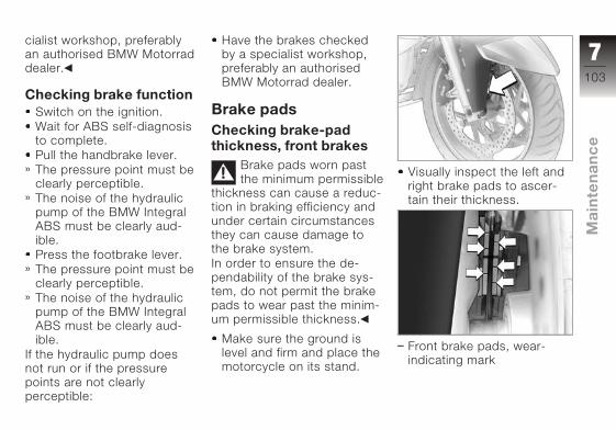
cialist workshop, preferably
an authorised BMW Motorrad
dealer.
Checking brake functionSwitch on the ignition.
Wait for ABS self-diagnosis
to complete.
Pull the handbrake lever.
The pressure point must be
clearly perceptible.
The noise of the hydraulic
pump of the BMW Integral
ABS must be clearly aud-
ible.
Press the footbrake lever.
The pressure point must be
clearly perceptible.
The noise of the hydraulic
pump of the BMW Integral
ABS must be clearly aud-
ible.
If the hydraulic pump does
not run or if the pressure
points are not clearly
perceptible:
Have the brakes checked
by a specialist workshop,
preferably an authorised
BMW Motorrad dealer.
Brake padsChecking brake-padthickness, front brakes
Brake pads worn past
the minimum permissible
thickness can cause a reduc-
tion in braking efficiency and
under certain circumstances
they can cause damage to
the brake system.
In order to ensure the de-
pendability of the brake sys-
tem, do not permit the brake
pads to wear past the minim-
um permissible thickness.
Make sure the ground is
level and firm and place the
motorcycle on its stand.
Visually inspect the left and
right brake pads to ascer-
tain their thickness.
Front brake pads, wear-
indicating mark
7103
z Mai
nte
nan
ce
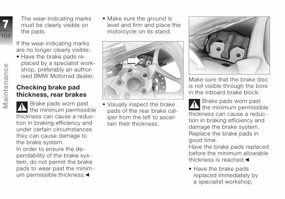
The wear-indicating marks
must be clearly visible on
the pads.
If the wear indicating marks
are no longer clearly visible:
Have the brake pads re-
placed by a specialist work-
shop, preferably an author-
ised BMW Motorrad dealer.
Checking brake padthickness, rear brakes
Brake pads worn past
the minimum permissible
thickness can cause a reduc-
tion in braking efficiency and
under certain circumstances
they can cause damage to
the brake system.
In order to ensure the de-
pendability of the brake sys-
tem, do not permit the brake
pads to wear past the minim-
um permissible thickness.
Make sure the ground is
level and firm and place the
motorcycle on its stand.
Visually inspect the brake
pads of the rear brake cal-
iper from the left to ascer-
tain their thickness.
Make sure that the brake disc
is not visible through the bore
in the inboard brake block.
Brake pads worn past
the minimum permissible
thickness can cause a reduc-
tion in braking efficiency and
damage the brake system.
Replace the brake pads in
good time.
Have the brake pads replaced
before the minimum allowable
thickness is reached.
Have the brake pads
replaced immediately by
a specialist workshop,
7104
z Mai
nte
nan
ce
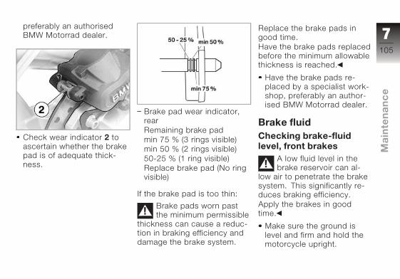
preferably an authorised
BMW Motorrad dealer.
Check wear indicator 2 to
ascertain whether the brake
pad is of adequate thick-
ness.
Brake pad wear indicator,
rear
Remaining brake pad
min 75 % (3 rings visible)
min 50 % (2 rings visible)
50-25 % (1 ring visible)
Replace brake pad (No ring
visible)
If the brake pad is too thin:
Brake pads worn past
the minimum permissible
thickness can cause a reduc-
tion in braking efficiency and
damage the brake system.
Replace the brake pads in
good time.
Have the brake pads replaced
before the minimum allowable
thickness is reached.
Have the brake pads re-
placed by a specialist work-
shop, preferably an author-
ised BMW Motorrad dealer.
Brake fluidChecking brake-fluidlevel, front brakes
A low fluid level in the
brake reservoir can al-
low air to penetrate the brake
system. This significantly re-
duces braking efficiency.
Apply the brakes in good
time.
Make sure the ground is
level and firm and hold the
motorcycle upright.
7105
z Mai
nte
nan
ce
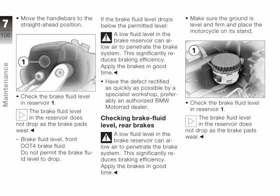
Move the handlebars to the
straight-ahead position.
Check the brake fluid level
in reservoir 1.
The brake fluid level
in the reservoir does
not drop as the brake pads
wear.
Brake fluid level, front
DOT4 brake fluid
Do not permit the brake flu-
id level to drop.
If the brake fluid level drops
below the permitted level:
A low fluid level in the
brake reservoir can al-
low air to penetrate the brake
system. This significantly re-
duces braking efficiency.
Apply the brakes in good
time.
Have the defect rectified
as quickly as possible by a
specialist workshop, prefer-
ably an authorised BMW
Motorrad dealer.
Checking brake-fluidlevel, rear brakes
A low fluid level in the
brake reservoir can al-
low air to penetrate the brake
system. This significantly re-
duces braking efficiency.
Apply the brakes in good
time.
Make sure the ground is
level and firm and place the
motorcycle on its stand.
Check the brake fluid level
in reservoir 1.
The brake fluid level
in the reservoir does
not drop as the brake pads
wear.
7106
z Mai
nte
nan
ce

Brake fluid level, rear
DOT4 brake fluid
Do not permit the brake flu-
id level to drop.
If the brake fluid level drops
below the permitted level:
A low fluid level in the
brake reservoir can al-
low air to penetrate the brake
system. This significantly re-
duces braking efficiency.
Apply the brakes in good
time.
Have the fault rectified as
soon as possible by a spe-
cialist workshop, preferably
an authorised BMW Motor-
rad dealer.
ClutchChecking clutch opera-tion
Pull the clutch lever.
The pressure point must be
clearly perceptible.
If the pressure point is not
clearly perceptible:
Have the clutch checked
by a specialist workshop,
preferably an authorised
BMW Motorrad dealer.
TyresChecking tyre treaddepth
Your motorcycle's hand-
ling and grip can be im-
paired even before the tyres
wear to the minimum tyre
tread depth permitted by law.
Have the tyres changed in
good time before they wear
to the minimum permissible
tread depth.
Make sure the ground is
level and firm and place the
motorcycle on its stand.
Measure the tyre tread
depth in the main tread
grooves with wear marks.
Tyres have wear indic-
ators integrated into the
main tread grooves. The tyre
is worn out when the tyre
tread has worn down to the
level of the marks. The loca-
tions of the marks are indic-
ated on the edge of the tyre,
e.g. by the letters TI, TWI or
by an arrow.
7107
z Mai
nte
nan
ce
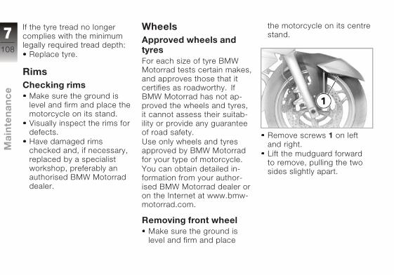
If the tyre tread no longer
complies with the minimum
legally required tread depth:
Replace tyre.
RimsChecking rims
Make sure the ground is
level and firm and place the
motorcycle on its stand.
Visually inspect the rims for
defects.
Have damaged rims
checked and, if necessary,
replaced by a specialist
workshop, preferably an
authorised BMW Motorrad
dealer.
WheelsApproved wheels andtyresFor each size of tyre BMW
Motorrad tests certain makes,
and approves those that it
certifies as roadworthy. If
BMW Motorrad has not ap-
proved the wheels and tyres,
it cannot assess their suitab-
ility or provide any guarantee
of road safety.
Use only wheels and tyres
approved by BMW Motorrad
for your type of motorcycle.
You can obtain detailed in-
formation from your author-
ised BMW Motorrad dealer or
on the Internet at www.bmw-
motorrad.com.
Removing front wheelMake sure the ground is
level and firm and place
the motorcycle on its centre
stand.
Remove screws 1 on left
and right.
Lift the mudguard forward
to remove, pulling the two
sides slightly apart.
7108
z Mai
nte
nan
ce

Once the calipers have
been removed, there is
a risk of the brake pads be-
ing pressed together to the
extent that they cannot be
slipped back over the brake
disc on reassembly.
Do not operate the handbrake
lever when the brake calipers
have been removed.
Remove securing screws 2of the left and right brake
calipers.
Force the brake pads
slightly apart by rocking
brake calipers 3 back
and forth A against brake
discs 4.
Mask off the parts of the
wheel rim that could be
scratched in the process of
removing the brake calipers.
Carefully pull the brake cal-
ipers back and out until
clear of the brake discs.
Raise the front of the mo-
torcycle until the front wheel
can rotate freely. BMW Mo-
torrad recommends the
BMW Motorrad front wheel
stand for lifting the motor-
cycle.
Fitting the front wheel stand
( 114)
Release axle clamping
screw 5.
Remove quick-release
axle 6, while supporting the
wheel.
BMW Motorrad can
supply an adapter for
removing the quick-release
axle. This adapter can
be combined with any
commercially available w/f 22
open-end or ring spanner.
7109
z Mai
nte
nan
ce
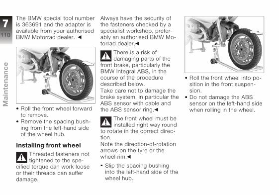
The BMW special tool number
is 363691 and the adapter is
available from your authorised
BMW Motorrad dealer.
Roll the front wheel forward
to remove.
Remove the spacing bush-
ing from the left-hand side
of the wheel hub.
Installing front wheelThreaded fasteners not
tightened to the spe-
cified torque can work loose
or their threads can suffer
damage.
Always have the security of
the fasteners checked by a
specialist workshop, prefer-
ably an authorised BMW Mo-
torrad dealer.
There is a risk of
damaging parts of the
front brake, particularly the
BMW Integral ABS, in the
course of the procedure
described below.
Take care not to damage the
brake system, in particular the
ABS sensor with cable and
the ABS sensor ring.
The front wheel must be
installed right way round
to rotate in the correct direc-
tion.
Note the direction-of-rotation
arrows on the tyre or the
wheel rim.
Slip the spacing bushing
into the left-hand side of the
wheel hub.
Roll the front wheel into po-
sition in the front suspen-
sion.
Do not damage the ABS
sensor on the left-hand side
when rolling in the wheel.
7110
z Mai
nte
nan
ce
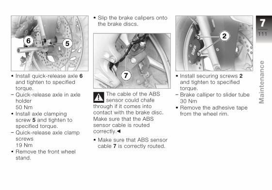
Install quick-release axle 6and tighten to specified
torque.
Quick-release axle in axle
holder
50 Nm
Install axle clamping
screw 5 and tighten to
specified torque.
Quick-release axle clamp
screws
19 Nm
Remove the front wheel
stand.
Slip the brake calipers onto
the brake discs.
The cable of the ABS
sensor could chafe
through if it comes into
contact with the brake disc.
Make sure that the ABS
sensor cable is routed
correctly.
Make sure that ABS sensor
cable 7 is correctly routed.
Install securing screws 2and tighten to specified
torque.
Brake calliper to slider tube
30 Nm
Remove the adhesive tape
from the wheel rim.
7111
z Mai
nte
nan
ce

Install screws 1 on left and
right.
Switch on the ignition.
Wait for self-diagnosis to
complete.
Operate the brake until the
pressure point is percept-
ible.
Removing rear wheelParts of the exhaust sys-
tem can be hot.
Do not touch hot parts of the
exhaust system.
Make sure the ground is
level and firm and place
the motorcycle on its centre
stand.
Slacken clamping screw 1on the silencer.
Do not remove the sealing
grease from the clamp.
Remove screw 2 for the
bracket of the end silencer
from the rear footrest.
Turn the end silencer out.
Engage first gear.
7112
z Mai
nte
nan
ce
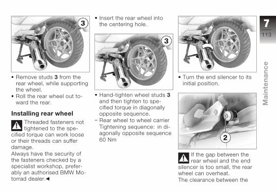
Remove studs 3 from the
rear wheel, while supporting
the wheel.
Roll the rear wheel out to-
ward the rear.
Installing rear wheelThreaded fasteners not
tightened to the spe-
cified torque can work loose
or their threads can suffer
damage.
Always have the security of
the fasteners checked by a
specialist workshop, prefer-
ably an authorised BMW Mo-
torrad dealer.
Insert the rear wheel into
the centering hole.
Hand-tighten wheel studs 3and then tighten to spe-
cified torque in diagonally
opposite sequence.
Rear wheel to wheel carrier
Tightening sequence: in di-
agonally opposite sequence
60 Nm
Turn the end silencer to its
initial position.
If the gap between the
rear wheel and the end
silencer is too small, the rear
wheel can overheat.
The clearance between the
7113
z Mai
nte
nan
ce

rear wheel and the end silen-
cer must be at least 20 mm.
Install screw 2 for the
bracket of the end silencer
in the rear footrest, but do
not tighten it.
Align clamp 1 on the end
silencer with mark A and
tighten to specified torque.
Torca clamp to silencer and
elbow
Thread-locking compound:
Optimoly TA
55 Nm
Tighten screw 2 securing
the bracket to the rear
footrest to specified torque.
Rear silencer to footrest
system
19 Nm
Front wheel standFront-wheel standA front wheel stand for
simple, safe changing of the
front wheel is available from
BMW Motorrad. The BMW
special tool number is 36
3 971 and the front wheel
stand is available from your
authorised BMW Motorrad
dealer. You also need the
adapters with the BMW
special tool number 36 3 973.
The BMW Motorrad
front wheel stand is
not designed to support
motorcycles not fitted with a
centre stand or without other
auxiliary stands. A motorcycle
resting only on the front wheel
stand and the rear wheel can
topple.
Place the motorcycle on its
centre stand or another aux-
iliary stand before lifting the
front wheel with the BMW
Motorrad front wheel stand.
Fitting the front wheelstand
Make sure the ground is
level and firm and place
the motorcycle on its centre
stand or the auxiliary stand.
7114
z Mai
nte
nan
ce

Slacken adjusting screws 1.
Push the two adapters 2apart until the front forks fit
between them.
Use locating pins 3 to set
the front wheel stand to the
desired height.
Centre the front wheel stand
relative to the front wheel
and push it against the front
axle.
Align the two adapters 2 so
that the front forks are se-
curely seated.
Tighten adjusting screws 1.
If the motorcycle is on
the centre stand and
is raised too far, the centre
stand will lift clear of the
ground and the motorcycle
could topple to one side.
When raising the motorcycle,
make sure that the centre
stand remains on the
ground.
Apply uniform pressure to
push the front wheel stand
down and raise the motor-
cycle.
7115
z Mai
nte
nan
ce

BulbsGeneral instructionsA warning appears in the mul-
tifunction display if a bulb is
defective. If the brake light
or rear light fails, the warn-
ing is accompanied by the
General warning light light-
ing up yellow. If the rear light
fails the second filament of
the brake light shines at re-
duced brightness to double
as a rear light. Even though
you have this substitute rear
light, the indicators in the dis-
play tell you that a bulb defect
has occurred.
A defective bulb places
your safety at risk be-
cause it is easier for other
users to oversee you and
your motorcycle.
Replace defective bulbs as
soon as possible; always
carry a complete set of spare
bulbs if possible.
The bulb is pressurised
and can cause injury if
damaged.
Wear protective goggles
and gloves when changing
bulbs.
The types of bulb fitted
to your motorcycle are
listed in the section entitled
"Technical data".
Do not touch the glass
of new bulbs with your
fingers. Use a clean, dry cloth
to hold the bulbs when hand-
ling them. Dirt deposits, in
particular oil and grease, in-
terfere with heat radiation
from the bulb. This leads to
overheating and shortens the
bulb's operating life.
Replacing high-beamheadlight bulb
If it is not standing firmly,
the motorcycle could
topple in the course of the
operations described below.
Always make sure that the
motorcycle is stable and
firmly supported.
Make sure the ground is
level and firm and place the
motorcycle on its stand.
Switch off the ignition.
Turn the handlebars to
the left to facilitate ac-
cess.
7116
z Mai
nte
nan
ce

Turn cover 1 counter-
clockwise and remove
it.
Disconnect plug 2.
Disengage spring clip 3 at
left and right and secure it
(preferably by hooking it into
the headlight housing).
Remove bulb 4.
Installation of the bulbs is
the reverse of the removal
procedure.
When installing, make sure
that lug 5 is pointing up and
that the bulb is securely
seated.
Check that the bulb is cor-
rected seated (by looking in
through the headlight lens).
7117
z Mai
nte
nan
ce
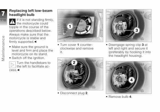
Replacing left low-beamheadlight bulb
If it is not standing firmly,
the motorcycle could
topple in the course of the
operations described below.
Always make sure that the
motorcycle is stable and
firmly supported.
Make sure the ground is
level and firm and place the
motorcycle on its stand.
Switch off the ignition.
Turn the handlebars to
the left to facilitate ac-
cess.
Turn cover 1 counter-
clockwise and remove
it.
Disconnect plug 2.
Disengage spring clip 3 at
left and right and secure it
(preferably by hooking it into
the headlight housing).
Remove bulb 4.
7118
z Mai
nte
nan
ce

Installation of the bulbs is
the reverse of the removal
procedure.
When installing, make sure
that lug 5 is pointing up and
that the bulb is securely
seated.
Check that the bulb is cor-
rected seated (by looking in
through the headlight lens).
Replacing rightlow-beam headlight bulb
If it is not standing firmly,
the motorcycle could
topple in the course of the
operations described below.
Always make sure that the
motorcycle is stable and
firmly supported.
Make sure the ground is
level and firm and place the
motorcycle on its stand.
Switch off the ignition.
Turn the handlebars to
the left to facilitate ac-
cess.
Turn cover 1 counter-
clockwise and remove
it.
Disconnect plug 2.
7119
z Mai
nte
nan
ce
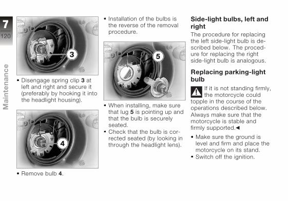
Disengage spring clip 3 at
left and right and secure it
(preferably by hooking it into
the headlight housing).
Remove bulb 4.
Installation of the bulbs is
the reverse of the removal
procedure.
When installing, make sure
that lug 5 is pointing up and
that the bulb is securely
seated.
Check that the bulb is cor-
rected seated (by looking in
through the headlight lens).
Side-light bulbs, left andrightThe procedure for replacing
the left side-light bulb is de-
scribed below. The proced-
ure for replacing the right
side-light bulb is analogous.
Replacing parking-lightbulb
If it is not standing firmly,
the motorcycle could
topple in the course of the
operations described below.
Always make sure that the
motorcycle is stable and
firmly supported.
Make sure the ground is
level and firm and place the
motorcycle on its stand.
Switch off the ignition.
7120
z Mai
nte
nan
ce

Apply firm forward pressure
with the flat of your hand to
push the mirror back out of
the anchorage.
While holding the side pan-
el, remove screw 1.
Remove fairing side panel 2.
The side-light bulb is ac-
cessible through the aper-
ture.
Turn bulb socket 3 counter-
clockwise to remove it from
the headlight housing; to
do so, pivot lever 4 at the
socket down (right side of
motorcycle: pivot the lever
up).
7121
z Mai
nte
nan
ce

Pull bulb 5 out of the bulb
holder.
Installation of the bulb is the
reverse of the removal pro-
cedure.
Check that the bulb is cor-
rected seated (by looking in
through the headlight lens).
When installing fairing pan-
el 2, make sure that the
lug of the panel is correctly
seated in the corresponding
recess.
The mirrors can easily
work loose from their an-
choring if the rubber holders
or snap-fit studs are greased.
Do not grease the rubber
holder or snap-fit stud.
When installing the mirror
housing, make sure that the
three plugs all engage in
their corresponding mounts.
7122
z Mai
nte
nan
ce
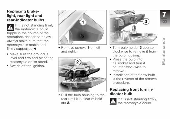
Replacing brake-light, rear light andrear-indicator bulbs
If it is not standing firmly,
the motorcycle could
topple in the course of the
operations described below.
Always make sure that the
motorcycle is stable and
firmly supported.
Make sure the ground is
level and firm and place the
motorcycle on its stand.
Switch off the ignition.
Remove screws 1 on left
and right.
Pull the bulb housing to the
rear until it is clear of hold-
ers 2.
Turn bulb holder 3 counter-
clockwise to remove it from
the bulb housing.
Press the bulb into
its socket and turn it
counter-clockwise to
remove.
Installation of the new bulb
is the reverse of the removal
procedure.
Replacing front turn in-dicator bulb
If it is not standing firmly,
the motorcycle could
7123
z Mai
nte
nan
ce
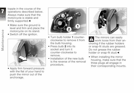
topple in the course of the
operations described below.
Always make sure that the
motorcycle is stable and
firmly supported.
Make sure the ground is
level and firm and place the
motorcycle on its stand.
Switch off the ignition.
Apply firm forward pressure
with the flat of your hand to
push the mirror out of the
anchorage.
Turn bulb holder 1 counter-
clockwise to remove it from
the bulb housing.
Press bulb 2 into its
socket and turn it
counter-clockwise to
remove.
Installation of the new bulb
is the reverse of the removal
procedure.
The mirrors can easily
work loose from their an-
choring if the rubber holders
or snap-fit studs are greased.
Do not grease the rubber
holder or snap-fit stud.
When installing the mirror
housing, make sure that the
three plugs all engage in
their corresponding mounts.
7124
z Mai
nte
nan
ce

Jump startingJump starting
The wires leading to the
power socket do not
have a load-capacity rating
adequate for jump-starting
the engine. Excessively high
current can lead to a cable
fire or damage to the vehicle
electronics.
Do not use the on-board
socket to jump-start the
engine of the motorcycle.
Touching live parts of
the ignition system with
the engine running can cause
electric shock.
Do not touch parts of the igni-
tion system when the engine
is running.
A short-circuit can result
if the crocodile clips of
the jump leads are accident-
ally brought into contact with
the motorcycle.
Use only jump leads fitted
with fully insulated crocodile
clips at both ends.
Jump-starting with a
donor-battery voltage
higher than 12 V can damage
the vehicle electronics.
Make sure that the battery
of the donor vehicle has a
voltage rating of 12 V.
Make sure the ground is
level and firm and place the
motorcycle on its stand.
Removing rear seat ( 57)
Removing front seat ( 57)
When jump-starting the en-
gine, do not disconnect the
battery from the on-board
electrical system.
Remove the protective cap
from the battery's positive
terminal.
Run the engine of the donor
vehicle during jump-starting.
Begin by connecting one
end of the red jump lead
to the positive terminal of
the discharged battery and
the other end to the pos-
itive terminal of the donor
battery.
Then connect one end of
the black jump lead to the
negative terminal of the
donor battery, and the other
end to the negative terminal
of the discharged battery.
Start the engine of the
vehicle with the discharged
battery in the usual way; if
the engine does not start,
wait a few minutes before
repeating the attempt
in order to protect the
starter motor and the donor
battery.
Allow both engines to idle
for a few minutes before
7125
z Mai
nte
nan
ce
disconnecting the jump
leads.
Disconnect the jump lead
from the negative terminals
first, then disconnect the
second lead from the posit-
ive terminals.
Do not use proprietary
start-assist sprays or
other products to start the
engine.
Installing front seat ( 58)
Installing rear seat ( 59)
BatteryMaintenance instructionsCorrect upkeep, recharging
and storage will prolong the
life of the battery and are es-
sential if warranty claims are
to be considered.
Compliance with the points
below is important in order to
maximise battery life:
Keep the surface of the bat-
tery clean and dry
Do not open the battery
Do not top up with water
Be sure to read and com-
ply with the instructions for
charging the battery on the
following pages
Do not turn the battery up-
side down
If the battery is not dis-
connected, the on-board
electronics (e.g. clock, etc.)
gradually drain the battery.
This can cause the battery to
run flat. If this happens, war-
ranty claims will not be ac-
cepted.
If the motorcycle is to be out
of use for more than four
weeks, disconnect the battery
or connect a suitable trickle
charger to the battery.
BMW Motorrad
has developed a
trickle-charger specially
designed for compatibility
with the electronics of your
motorcycle. Using this
charger, you can keep the
battery charged during long
periods of disuse, without
having to disconnect the
battery from the motorcycle's
on-board systems. You can
obtain additional information
from your authorised
BMW Motorrad dealer.
Charging battery whenconnected
Charging the connec-
ted battery directly at the
battery terminals can damage
the vehicle electronics.
Always disconnect the battery
from the on-board circuits be-
fore recharging it with a char-
7126
z Mai
nte
nan
ce
ger connected directly to the
battery posts.
Only chargers suitable
for this mode of char-
ging can be used to recharge
the battery via the on-board
socket. Unsuitable chargers
could cause damage to the
motorcycle's on-board elec-
trics.
Use BMW chargers with the
part numbers 71 60 7 688
864 (220 V) or, as applicable,
71 60 7 688 865 (110 V). If
you are in doubt, disconnect
the battery from the on-board
systems and connect the
charger directly to the bat-
tery.
If you switch on the ig-
nition and the multifunc-
tion display and telltale lights
fail to light up, the battery is
completely flat. Attempting to
charge a completely flat bat-
tery via the on-board socket
can cause damage to the mo-
torcycle's electronics.
If a battery has discharged to
the extent that it is completely
flat, it has to be disconnec-
ted from the on-board circuits
and charged with the char-
ger connected directly to the
battery posts.
Charge via the power sock-
et, with the battery connec-
ted to the motorcycle's on-
board electrical system.
The motorcycle's
on-board electronics
know when the battery is
fully charged. The on-board
socket is switched off when
this happens.
Comply with the operating
instructions of the charger.
If you are unable to
charge the battery
through the power socket,
you may be using a charger
that is not compatible with
your motorcycle's electronics.
If this happens, disconnect
the battery from the on-board
systems and connect the
charger directly to the
battery.
Charging the batterywhen disconnected
Charge the battery using a
suitable charger.
Comply with the operating
instructions of the charger.
Once the battery is fully
charged, disconnect the
charger terminal clips from
the battery terminals.
The battery has to be re-
charged at regular inter-
vals in the course of a lengthy
period of disuse. See the in-
structions for caring for your
battery. Always fully recharge
the battery before restoring it
to use
7127
z Mai
nte
nan
ce

Removing the batteryMake sure the ground is
level and firm and place the
motorcycle on its stand.
Removing rear seat ( 57)
Removing front seat ( 57)
Switch off the ignition.
Disconnection in
the wrong sequence
increases the risk of
short-circuits.
Always proceed in the correct
sequence.
Remove screw 1.
Disconnect battery negative
lead 2 first.
Then pull back the protect-
ive cap and disconnect bat-
tery positive lead 3.
Lift the battery up and out;
work it slightly back and
forth if it is difficult to re-
move.
Installing batteryMake sure the ground is
level and firm and place the
motorcycle on its stand.
Switch off the ignition.
Insert the battery into the
battery compartment, with
the positive terminal on the
right in the forward direction
of travel.
Engage the battery retainer
at the bottom, slip it over
the battery and tighten
screw 1 to the specified
torque.
Connection in the wrong
sequence increases the
risk of short-circuits.
Always proceed in the correct
sequence.
Never install the battery
without the protective cap.
Connect positive lead 3 first
and tighten the fastener un-
til hand-tight.
7128
z Mai
nte
nan
ce
Fit the protective cap to the
positive terminal of the bat-
tery.
Then connect negative
lead 2 and tighten the
fastener until hand-tight.
Switch on the ignition.
Without starting the engine,
fully open the throttle for at
least one second so that
the control unit of the en-
gine management system
can register the throttle-
valve positions.
Switch off the ignition.
Installing front seat ( 58)
Installing rear seat ( 59)
Setting the clock ( 42)
7129
z Mai
nte
nan
ce

7130
z Mai
nte
nan
ce

Care
Care products . . . . . . . . . . . . . . . . 132
Washing the motorcycle . . . . . . 132
Cleaning easily damagedcomponents . . . . . . . . . . . . . . . . . 133
Paint care . . . . . . . . . . . . . . . . . . . . 134
Protective wax coating. . . . . . . . 134
Laying up the motorcycle . . . . . 134
Restoring motorcycle touse . . . . . . . . . . . . . . . . . . . . . . . . . . 135
8131
z Car
e
Care productsBMW Motorrad recommends
that you use the cleaning
and care products you can
obtain from your authorised
BMW Motorrad dealer. The
substances in BMW Care
Products have been tested
in laboratories and in prac-
tice; they provide optimised
care and protection for the
materials used in your vehicle.
The use of unsuitable
cleaning and care
products can damage vehicle
components.
Do not use solvents such as
cellulose thinners, cold clean-
ers, fuel or the like, and do
not use cleaning products
that contain alcohol.
Washing the motor-cycleBMW Motorrad recommends
that you use BMW insect re-
mover to soften and wash off
insects and stubborn dirt on
painted parts prior to washing
the motorcycle.
To prevent stains, do
not wash the motorcycle
immediately after it has been
exposed to strong sunlight
and do not wash it in the sun.
Make sure that the motor-
cycle is washed frequently,
especially during the winter
months.
To remove road salt, clean
the motorcycle with cold wa-
ter immediately after every
trip.
After the motorcycle has
been washed, ridden
through water or ridden in
the rain, the brake discs and
pads might be wet and the
brakes might not take effect
immediately.
Apply the brakes in good time
until the brakes have dried
out.
Warm water intensifies
the effect of salt.
Use only cold water to wash
off road salt.
The high pressure of
steam cleaners can
damage seals, the hydraulic
brake system, the electrical
system, and the seat.
Do not use a steam jet or
high-pressure cleaning equip-
ment.
8132
z Car
e

Cleaning easily dam-aged componentsPlasticsClean plastic parts with water
and BMW plastic care emul-
sion. This includes in particu-
lar:
Windscreen
Headlight lens made of
plastic
Glass cover of the instru-
ment cluster
Black, unpainted parts
If plastic parts are
cleaned using unsuitable
cleaning agents, the surfaces
can be damaged.
Do not use cleaning agents
that contain alcohol, solvents
or abrasives to clean plastic
parts.
Even fly-remover pads or
cleaning pads with hard
surfaces can produce
scratches.
Soften stubborn dirt and
insects by covering the
affected areas with a wet
cloth.
WindscreenClean off dirt and insects with
a soft sponge and plenty of
water.
Fuel and chemical
solvents attack the
material of the windscreen;
the windscreen becomes
opaque or dull.
Do not use cleaning agents.
ChromeUse plenty of water and BMW
shampoo to clean chrome,
particularly if it has been
exposed to road salt. Use
chrome polish for additional
treatment.
RadiatorClean the radiator regularly to
prevent overheating of the en-
gine due to inadequate cool-
ing.
For example, use a garden
hose with low water pressure.
Cooling fins can be bent
easily.
Take care not to bend the fins
when cleaning the radiator.
RubberTreat rubber components with
water or BMW rubber-care
products.
Using silicone sprays for
the care of rubber seals
can cause damage.
Do not use silicone sprays
or other care products that
contain silicon.
8133
z Car
e
Paint careWashing the motorcycle
regularly will help counteract
the long-term effects of
substances that damage
the paint, especially if your
motorcycle is ridden in areas
with high air pollution or
natural sources of dirt, for
example tree resin or pollen.
Remove particularly
aggressive substances
immediately, however, as
otherwise the paint can
be affected or become
discoloured. Substances
of this nature include spilt
fuel, oil, grease, brake fluid
and bird droppings. We
recommend BMW vehicle
polish or BMW paint cleaner
for this purpose.
Marks on the paintwork are
particularly easy to see after
the motorcycle has been
washed. Remove stains of
this kind immediately, using
cleaning-grade benzene or
petroleum spirit on a clean
cloth or ball of cotton wool.
BMW Motorrad recommends
BMW tar remover for
removing specks of tar.
Remember to wax the parts
treated in this way.
Protective wax coat-ingBMW Motorrad recommends
applying only BMW car
wax or products containing
carnauba wax or synthetic
wax.
It is time to rewax the paint-
work when water "puddles"
on the surface, instead of
forming beads.
Laying up the motor-cycle
Clean the motorcycle.
Remove the battery.
Spray the brake and clutch
lever pivots and the main
and side stand pivots with a
suitable lubricant.
Coat bright metal and
chrome-plated parts with
an acid-free grease (e.g.
Vaseline).
Stand the motorcycle in
a dry room in such a way
that there is no load on
either wheel. Authorised
BMW Motorrad dealers can
provide suitable auxiliary
stands.
Before laying the vehicle
up out of use, have the
engine oil and the oil filter ele-
ment changed by a special-
ist workshop, preferably an
authorised BMW Motorrad
dealer. Combine work for lay-
ing up/restoring to use with a
BMW service or inspection.
8134
z Car
e

Restoring motorcycleto use
Remove the protective wax
coating.
Clean the motorcycle.
Install a charged battery.
Before starting: work
through the checklist.
8135
z Car
e

8136
z Car
e

Technical data
Troubleshooting chart . . . . . . . . 138
Threaded fasteners . . . . . . . . . . . 138
Engine . . . . . . . . . . . . . . . . . . . . . . . 139
Riding specifications . . . . . . . . . 141
Clutch . . . . . . . . . . . . . . . . . . . . . . . 142
Transmission . . . . . . . . . . . . . . . . . 142
Rear-wheel drive . . . . . . . . . . . . . 143
Running gear . . . . . . . . . . . . . . . . . 143
Brakes . . . . . . . . . . . . . . . . . . . . . . . 144
Wheels and tyres . . . . . . . . . . . . . 145
Electrics . . . . . . . . . . . . . . . . . . . . . 146
Frame . . . . . . . . . . . . . . . . . . . . . . . 148
Dimensions . . . . . . . . . . . . . . . . . . 148
Weights . . . . . . . . . . . . . . . . . . . . . . 149
9137
z Te
ch
nic
al d
ata

Troubleshooting chartEngine does not start at all or is difficult to start.
Possible cause Remedy
Kill switch activated. Kill switch in operating position (run).
Side stand extended and gear engaged. Retract the side stand ( 70).
Gear engaged and clutch not disengaged. Select neutral or pull clutch lever( 70).
Clutch pulled when ignition was OFF Switch on the ignition, then pull the clutch
lever.
No fuel in tank. Refuelling ( 84)
Battery not adequately charged. Charging battery when connected ( 126)
Threaded fastenersActivity Type of threaded connection Tightening
torques
Front wheel
Quick-release axle clamp screws M8 x 35 19 Nm
Quick-release axle in axle holder M24 x 1.5 50 Nm
Brake calliper to slider tube M8 x 32 - 10.9 30 Nm
9138
z Te
ch
nic
al d
ata

Activity Type of threaded connection Tighteningtorques
Rear wheel
Rear wheel to wheel carrier 60 Nm
Rear silencer to footrest system M8 19 Nm
Torca clamp to silencer and elbow M8, Optimoly TA 55 Nm
Engine
Engine, type four-stroke opposed twin, air-cooled with oil-
cooled exhaust ports, installed longitudinally,
two overhead camshafts, electronic fuel injec-
tion
Effective displacement 1170 cm3
Cylinder bore 101 mm
Piston stroke 73 mm
Compression ratio 12.0 : 1
Nominal output 81 kW, at engine rpm: 7500 min-1
with OE Power reduction: 74 kW, at engine rpm: 7500 min-1
Max. torque 115 Nm, over: 6000 min-1
Maximum permissible engine speed 8000 min-1
9139
z Te
ch
nic
al d
ata
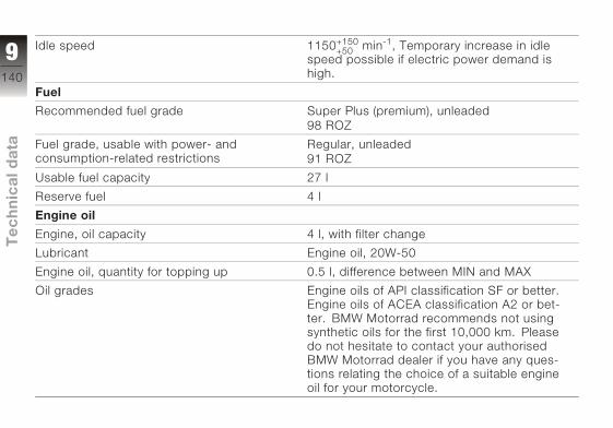
Idle speed 1150+150+50
min-1, Temporary increase in idle
speed possible if electric power demand is
high.
Fuel
Recommended fuel grade Super Plus (premium), unleaded
98 ROZ
Fuel grade, usable with power- and
consumption-related restrictions
Regular, unleaded
91 ROZ
Usable fuel capacity 27 l
Reserve fuel 4 l
Engine oil
Engine, oil capacity 4 l, with filter change
Lubricant Engine oil, 20W-50
Engine oil, quantity for topping up 0.5 l, difference between MIN and MAX
Oil grades Engine oils of API classification SF or better.
Engine oils of ACEA classification A2 or bet-
ter. BMW Motorrad recommends not using
synthetic oils for the first 10,000 km. Please
do not hesitate to contact your authorised
BMW Motorrad dealer if you have any ques-
tions relating the choice of a suitable engine
oil for your motorcycle.
9140
z Te
ch
nic
al d
ata
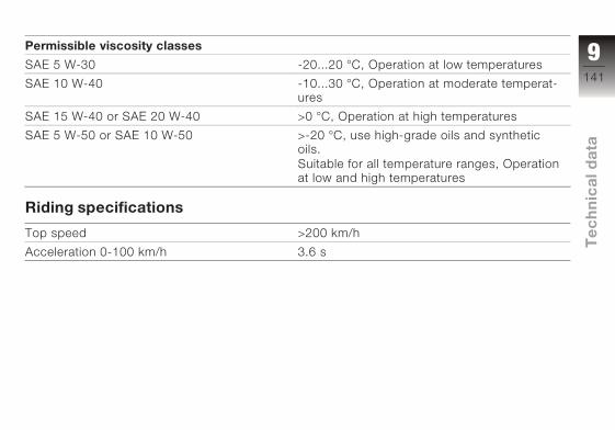
Permissible viscosity classes
SAE 5 W-30 -20...20 °C, Operation at low temperatures
SAE 10 W-40 -10...30 °C, Operation at moderate temperat-
ures
SAE 15 W-40 or SAE 20 W-40 >0 °C, Operation at high temperatures
SAE 5 W-50 or SAE 10 W-50 >-20 °C, use high-grade oils and synthetic
oils.
Suitable for all temperature ranges, Operation
at low and high temperatures
Riding specifications
Top speed >200 km/h
Acceleration 0-100 km/h 3.6 s
9141
z Te
ch
nic
al d
ata
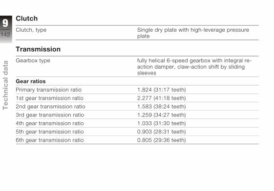
Clutch
Clutch, type Single dry plate with high-leverage pressure
plate
Transmission
Gearbox type fully helical 6-speed gearbox with integral re-
action damper, claw-action shift by sliding
sleeves
Gear ratios
Primary transmission ratio 1.824 (31:17 teeth)
1st gear transmission ratio 2.277 (41:18 teeth)
2nd gear transmission ratio 1.583 (38:24 teeth)
3rd gear transmission ratio 1.259 (34:27 teeth)
4th gear transmission ratio 1.033 (31:30 teeth)
5th gear transmission ratio 0.903 (28:31 teeth)
6th gear transmission ratio 0.805 (29:36 teeth)
9142
z Te
ch
nic
al d
ata
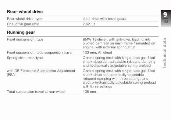
Rear-wheel drive
Rear wheel drive, type shaft drive with bevel gears
Final drive gear ratio 2.62 : 1
Running gear
Front suspension, type BMW Telelever, with anti-dive, leading link
pivoted centrally on main frame / mounted on
engine, with external spring strut
Front suspension, total suspension travel 120 mm, At wheel
Spring strut, rear, type Central spring strut with single-tube gas-filled
shock absorber, adjustable rebound damping
and hydraulically adjustable spring preload
with OE Electronic Suspension Adjustment
(ESA):
Central spring strut with single-tube gas-filled
shock absorber, electrically adjustable
rebound damping with three settings and
electro-hydraulically adjustable spring preload
with three settings
Total suspension travel at rear wheel 135 mm
9143
z Te
ch
nic
al d
ata
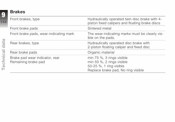
Brakes
Front brakes, type Hydraulically operated twin disc brake with 4-
piston fixed calipers and floating brake discs
Front brake pads Sintered metal
Front brake pads, wear-indicating mark The wear-indicating marks must be clearly vis-
ible on the pads.
Rear brakes, type Hydraulically operated disc brake with
2-piston floating caliper and fixed disc
Rear brake pads Organic material
Brake pad wear indicator, rear
Remaining brake pad
min 75 %, 3 rings visible
min 50 %, 2 rings visible
50-25 %, 1 ring visible
Replace brake pad, No ring visible
9144
z Te
ch
nic
al d
ata
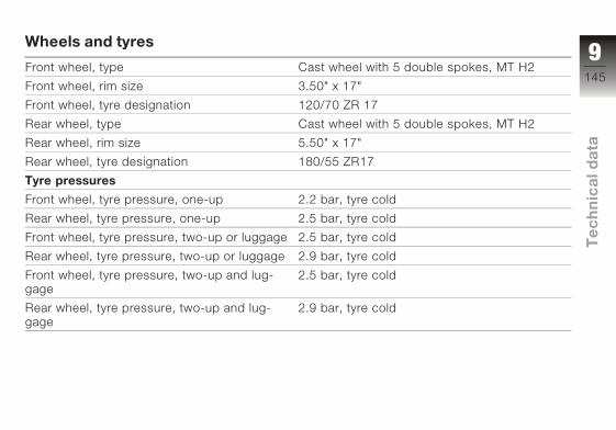
Wheels and tyres
Front wheel, type Cast wheel with 5 double spokes, MT H2
Front wheel, rim size 3.50" x 17"
Front wheel, tyre designation 120/70 ZR 17
Rear wheel, type Cast wheel with 5 double spokes, MT H2
Rear wheel, rim size 5.50" x 17"
Rear wheel, tyre designation 180/55 ZR17
Tyre pressures
Front wheel, tyre pressure, one-up 2.2 bar, tyre cold
Rear wheel, tyre pressure, one-up 2.5 bar, tyre cold
Front wheel, tyre pressure, two-up or luggage 2.5 bar, tyre cold
Rear wheel, tyre pressure, two-up or luggage 2.9 bar, tyre cold
Front wheel, tyre pressure, two-up and lug-
gage
2.5 bar, tyre cold
Rear wheel, tyre pressure, two-up and lug-
gage
2.9 bar, tyre cold
9145
z Te
ch
nic
al d
ata

Electrics
Current limit value, on-board sockets 10 A
Fuses All circuits are electronically protected, so
plug-in fuses are no longer necessary. If an
electronic fuse trips and de-energises a cir-
cuit, the circuit is active as soon as the ig-
nition is switched on after the fault has been
rectified.
Battery
Type, battery Gel battery
Battery rated voltage 12 V
Battery rated capacity 19 Ah
Spark plugs
Spark plug, manufacturer and designation Bosch YR5LDE
Spark plug, electrode gap
When new
0.8±0.1 mm
Spark plug, electrode gap
Wear limit
1 mm
9146
z Te
ch
nic
al d
ata

Lighting
High-beam headlight bulb, standard designa-
tion
H7 halogen bulb
High-beam headlight bulb, voltage 12 V
High-beam headlight bulb, power 55 W
Low-beam headlight bulb, standard designa-
tion
H7 halogen bulb
Low-beam headlight bulb, voltage 12 V
Low-beam headlight bulb, power 55 W
Parking light bulb, standard designation Bulb T8/4
Parking light bulb, voltage 12 V
Parking light bulb, power 5 W
Tail light / brake light bulb, standard designa-
tion
Bulb, P25-1 (rear light dimmed)
Tail light / brake light bulb, voltage 12 V
Tail light / brake light bulb, standard designa-
tion
21 W
Flashing turn indicator bulbs, standard desig-
nation
Bulb, P21W
with OE White turn indicators: Bulb, PY21W
9147
z Te
ch
nic
al d
ata
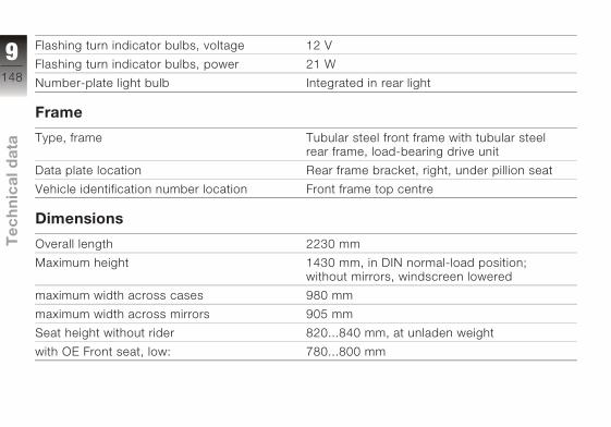
Flashing turn indicator bulbs, voltage 12 V
Flashing turn indicator bulbs, power 21 W
Number-plate light bulb Integrated in rear light
Frame
Type, frame Tubular steel front frame with tubular steel
rear frame, load-bearing drive unit
Data plate location Rear frame bracket, right, under pillion seat
Vehicle identification number location Front frame top centre
Dimensions
Overall length 2230 mm
Maximum height 1430 mm, in DIN normal-load position;
without mirrors, windscreen lowered
maximum width across cases 980 mm
maximum width across mirrors 905 mm
Seat height without rider 820...840 mm, at unladen weight
with OE Front seat, low: 780...800 mm
9148
z Te
ch
nic
al d
ata

Weights
Unladen weight 259 kg, DIN unladen weight, ready for road
90 % load of fuel, without optional extras
Permitted gross weight 495 kg
Maximum payload 236 kg
9149
z Te
ch
nic
al d
ata

9150
z Te
ch
nic
al d
ata

Service
BMW Motorrad service . . . . . . . 152
BMW Motorrad servicequality . . . . . . . . . . . . . . . . . . . . . . . 152
BMW Motorrad Service Card:On-the-spot breakdownassistance . . . . . . . . . . . . . . . . . . . 153
BMW Motorrad servicenetwork . . . . . . . . . . . . . . . . . . . . . . 153
Maintenance work . . . . . . . . . . . . 153
Maintenance schedules . . . . . . . 154
Confirmation of maintenancework . . . . . . . . . . . . . . . . . . . . . . . . . 155
Confirmation of service . . . . . . . 160
10151
z Se
rvic
e

BMW Motorrad ser-viceAdvanced technology
requires specially adapted
methods of maintenance and
repair.
If maintenance and re-
pair work is performed
inexpertly, it could result in
consequential damage and
thus constitute a safety risk.
BMW recommends that you
have the necessary work on
your motorcycle performed
either by an authorised BMW
Motorrad dealer or by a work-
shop that operates to BMW
specifications and employs
suitably trained personnel.
Your authorised BMW Motor-
rad dealer can provide inform-
ation on the specified Ser-
vice, Inspection and Annual
Inspection work needed.
Have all maintenance and
repair work carried out
confirmed in the "Service"
chapter in this manual.
Authorised BMW Motorrad
dealers are supplied with the
latest technical information
and have the necessary tech-
nical know-how. BMW Mo-
torrad recommends that you
contact your authorised BMW
Motorrad dealer if you have
any questions regarding your
motorcycle.
BMW Motorrad servicequalityAlong with its reputation for
engineering quality and high
reliability, BMW Motorrad is a
byword for excellent quality of
service.
To ensure that your BMW is
always in optimum condition,
BMW Motorrad recommends
that you have the mainten-
ance work required for your
motorcycle carried out on
schedule, preferably by your
authorised BMW Motorrad
dealer. For generous treat-
ment of claims submitted
after the warranty period has
expired, evidence of regular
maintenance is essential.
Certain signs of wear,
moreover, may otherwise not
be noticed until it is too late
to put them right at moderate
cost. Your authorised BMW
Motorrad dealer's mechanics
know every detail of your
motorcycle and can take
remedial action if necessary
before minor faults develop
into serious problems. By
having the necessary repairs
done properly and in good
time, you save time and
money in the long run.
10152
z Se
rvic
e
BMW MotorradService Card: On-the-spot breakdownassistanceIn the event of a breakdown,
the BMW Motorrad Service
Card issued with each new
BMW motorcycle enables
you to access an extensive
range of services such as
breakdown assistance, mo-
torcycle transportation etc.
(details can differ from coun-
try to country). In the event of
a breakdown, contact BMW
Motorrad's Mobile Service.
The specialists will provide
the necessary advice and as-
sistance.
You will find important
country-specific contact
addresses and the after-sales
service organisation phone
numbers in the "Service
Kontakt / Service Contact"
brochures, along with
information on Mobile Service
and the dealership network.
BMW Motorrad servicenetworkBMW Motorrad's extensive
after-sales service network is
in place to look after you and
your motorcycle in more than
100 countries. In Germany
alone, you have the best pos-
sible access to approximately
200 authorised BMW Motor-
rad dealers.
All information concerning
the international dealership
network can be found in the
brochures entitled "Service
Contact Europe" and "Service
Contact Africa, America, Asia,
Australia, Oceania".
Maintenance workintervalsSome maintenance tasks
have to be performed after
a certain time, others depend
on the distance covered by
the motorcycle.
BMW Running-in CheckThe BMW running-in check
has to be performed when
the motorcycle has covered
between 500 km and 1,200
km
BMW Annual InspectionSome maintenance work has
to be carried out at least once
a year. Other tasks depend
on the distance the motor-
cycle has covered.
10153
z Se
rvic
e
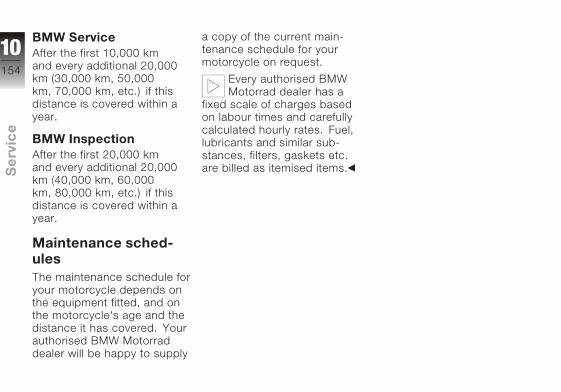
BMW ServiceAfter the first 10,000 km
and every additional 20,000
km (30,000 km, 50,000
km, 70,000 km, etc.) if this
distance is covered within a
year.
BMW InspectionAfter the first 20,000 km
and every additional 20,000
km (40,000 km, 60,000
km, 80,000 km, etc.) if this
distance is covered within a
year.
Maintenance sched-ulesThe maintenance schedule for
your motorcycle depends on
the equipment fitted, and on
the motorcycle's age and the
distance it has covered. Your
authorised BMW Motorrad
dealer will be happy to supply
a copy of the current main-
tenance schedule for your
motorcycle on request.
Every authorised BMW
Motorrad dealer has a
fixed scale of charges based
on labour times and carefully
calculated hourly rates. Fuel,
lubricants and similar sub-
stances, filters, gaskets etc.
are billed as itemised items.
10154
z Se
rvic
e

Confirmation of maintenance work
BMW Pre-deliveryCheckCarried out in accord-
ance with manufacturer's
instructions
Date, stamp, signature
BMW Running-inCheckCarried out in accord-
ance with manufacturer's
instructions
Odometer reading
Brake fluid, newWithout BMW Integ-
ral ABSWith BMW Integral
ABSWheel circuitControl circuit
Date, stamp, signature
10155
z Se
rvic
e

BMW ServiceBMW Annual In-
spectionBMW ServiceBMW Inspection
Carried out in accord-
ance with manufacturer's
instructions
Odometer reading
Brake fluid, newWithout BMW Integ-
ral ABSWith BMW Integral
ABSWheel circuitControl circuit
Date, stamp, signature
BMW ServiceBMW Annual In-
spectionBMW ServiceBMW Inspection
Carried out in accord-
ance with manufacturer's
instructions
Odometer reading
Brake fluid, newWithout BMW Integ-
ral ABSWith BMW Integral
ABSWheel circuitControl circuit
Date, stamp, signature
BMW ServiceBMW Annual In-
spectionBMW ServiceBMW Inspection
Carried out in accord-
ance with manufacturer's
instructions
Odometer reading
Brake fluid, newWithout BMW Integ-
ral ABSWith BMW Integral
ABSWheel circuitControl circuit
Date, stamp, signature
10156
z Se
rvic
e

BMW ServiceBMW Annual In-
spectionBMW ServiceBMW Inspection
Carried out in accord-
ance with manufacturer's
instructions
Odometer reading
Brake fluid, newWithout BMW Integ-
ral ABSWith BMW Integral
ABSWheel circuitControl circuit
Date, stamp, signature
BMW ServiceBMW Annual In-
spectionBMW ServiceBMW Inspection
Carried out in accord-
ance with manufacturer's
instructions
Odometer reading
Brake fluid, newWithout BMW Integ-
ral ABSWith BMW Integral
ABSWheel circuitControl circuit
Date, stamp, signature
BMW ServiceBMW Annual In-
spectionBMW ServiceBMW Inspection
Carried out in accord-
ance with manufacturer's
instructions
Odometer reading
Brake fluid, newWithout BMW Integ-
ral ABSWith BMW Integral
ABSWheel circuitControl circuit
Date, stamp, signature
10157
z Se
rvic
e
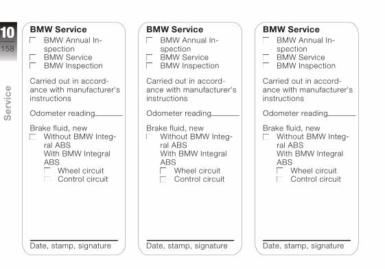
BMW ServiceBMW Annual In-
spectionBMW ServiceBMW Inspection
Carried out in accord-
ance with manufacturer's
instructions
Odometer reading
Brake fluid, newWithout BMW Integ-
ral ABSWith BMW Integral
ABSWheel circuitControl circuit
Date, stamp, signature
BMW ServiceBMW Annual In-
spectionBMW ServiceBMW Inspection
Carried out in accord-
ance with manufacturer's
instructions
Odometer reading
Brake fluid, newWithout BMW Integ-
ral ABSWith BMW Integral
ABSWheel circuitControl circuit
Date, stamp, signature
BMW ServiceBMW Annual In-
spectionBMW ServiceBMW Inspection
Carried out in accord-
ance with manufacturer's
instructions
Odometer reading
Brake fluid, newWithout BMW Integ-
ral ABSWith BMW Integral
ABSWheel circuitControl circuit
Date, stamp, signature
10158
z Se
rvic
e

BMW ServiceBMW Annual In-
spectionBMW ServiceBMW Inspection
Carried out in accord-
ance with manufacturer's
instructions
Odometer reading
Brake fluid, newWithout BMW Integ-
ral ABSWith BMW Integral
ABSWheel circuitControl circuit
Date, stamp, signature
BMW ServiceBMW Annual In-
spectionBMW ServiceBMW Inspection
Carried out in accord-
ance with manufacturer's
instructions
Odometer reading
Brake fluid, newWithout BMW Integ-
ral ABSWith BMW Integral
ABSWheel circuitControl circuit
Date, stamp, signature
BMW ServiceBMW Annual In-
spectionBMW ServiceBMW Inspection
Carried out in accord-
ance with manufacturer's
instructions
Odometer reading
Brake fluid, newWithout BMW Integ-
ral ABSWith BMW Integral
ABSWheel circuitControl circuit
Date, stamp, signature
10159
z Se
rvic
e
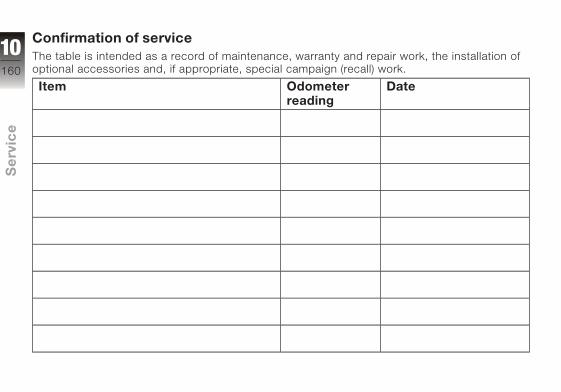
Confirmation of serviceThe table is intended as a record of maintenance, warranty and repair work, the installation of
optional accessories and, if appropriate, special campaign (recall) work.
Item Odometerreading
Date
10160
z Se
rvic
e
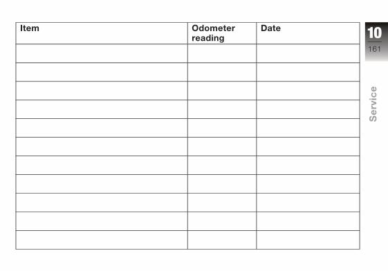
Item Odometerreading
Date 10161
z Se
rvic
e

AAbbreviations and symbols, 6
ABSwarning light, 23
Accessoriesgeneral instructions, 90
Anti-theft alarm, 18
BBattery
charging battery when
connected, 126
charging the battery when
disconnected, 127
installation, 128
maintenance instruc-
tions, 126
removal, 128
warning, battery charge
current, 27
Brake fluidchecking fluid level, front
brakes, 105
checking fluid level, rear
brakes, 106
Brake leverAdjusting handbrake
lever, 52
Brake pads
checking front, 103
checking rear, 104
running in, 73
Brakes, 103BMW Integral ABS, 86
fluid reservoir, rear, 15
front fluid reservoir, 11
safety instructions, 85
technical data, 144
Bulbsgeneral instructions, 116
replacing brake-light
bulb, 123
replacing front turn indicator
bulb, 123
replacing high-beam
headlight bulb, 116
replacing left low-beam
headlight bulb, 118
replacing parking-light
bulb, 120
replacing rear light
bulb, 123
replacing rear turn indicator
bulb, 123
replacing right low-beam
headlight bulb, 119
technical data, 147
warning, bulb failure, 28
CCase
closing, 94
installing, 96
opening, 94
removing, 95
Centre standplacing motorcycle on
centre stand, 81
removing motorcycle from
centre stand, 83
Checklist, 70
Clockadjusting, 18, 42
ClutchAdjusting clutch lever, 51
Checking operation, 107
11162
z Ind
ex
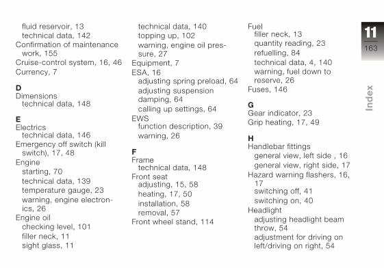
fluid reservoir, 13
technical data, 142
Confirmation of maintenance
work, 155
Cruise-control system, 16, 46
Currency, 7
DDimensions
technical data, 148
EElectrics
technical data, 146
Emergency off switch (kill
switch), 17, 48
Engine
starting, 70
technical data, 139
temperature gauge, 23
warning, engine electron-
ics, 26
Engine oil
checking level, 101
filler neck, 11
sight glass, 11
technical data, 140
topping up, 102
warning, engine oil pres-
sure, 27
Equipment, 7
ESA, 16adjusting spring preload, 64
adjusting suspension
damping, 64
calling up settings, 64
EWSfunction description, 39
warning, 26
FFrame
technical data, 148
Front seatadjusting, 15, 58
heating, 17, 50
installation, 58
removal, 57
Front wheel stand, 114
Fuelfiller neck, 13
quantity reading, 23
refuelling, 84
technical data, 4, 140
warning, fuel down to
reserve, 26
Fuses, 146
GGear indicator, 23
Grip heating, 17, 49
HHandlebar fittings
general view, left side , 16
general view, right side, 17
Hazard warning flashers, 16,
17switching off, 41
switching on, 40
Headlight
adjusting headlight beam
throw, 54
adjustment for driving on
left/driving on right, 54
11163
z Ind
ex

high-beam headlight, 19
low-beam headlight, 19
side lights, 19
Helmet holder, 15, 60
High-beam headlight, 16
telltale light, 23
Horn, 16
IIdle
telltale light, 23
Ignition
switching off, 38
switching on, 38
Ignition switch, 38
Immobiliserfunction description, 39
warning, 26
Instrument clusteroverview, 18
sensor for lighting, 18
KKeys, 40
LLaying up, 134
Lights
adjusting headlight beam
throw, 11, 54
switching off the parking
lights, 54
switching on the high-beam
headlight, 53
switching on the low-beam
headlight, 53
switching on the parking
lights, 53
switching on the side
lights, 52
MMaintenance
general instructions, 100
Mirrorsadjusting, 60
Multifunction display, 18
OOdometer and tripmeters
odometer, 41
resetting the tripmeter, 42
selecting the tripmeter, 41
On-board computer
resetting average consump-
tion, 44
resetting average speed, 44
residual range, 43
selecting readings, 43
PPower socket, 11, 90
Pre-ride check, 71
RRear seat
heating, 13, 50
installation, 59
removal, 57
Rear-wheel drivetechnical data, 143
Refuelling, 84
11164
z Ind
ex

Reservewarning, 26
Residual range, 43
Restoring to use, 135
Rev. counter, 18
Running gear
technical data, 143
Running in, 73
SSafety instructions, 68
brakes, 85
Service, 152
Service Card, 153
Side standplacing motorcycle on side
stand, 77
removing motorcycle from
side stand, 79
starting the engine, 70
Spark plugs
technical data, 146
Speedometer, 18
Spring preload, rear
adjusting, 15, 61
Starter, 17
Starting, 70
Steering lock
locking, 39
Stowage compartment, 56
Suspension damping, rear
adjusting, 11, 62
TTechnical data
brakes, 144
bulbs, 147
clutch, 142
dimensions, 148
electrics, 146
engine, 139
engine oil, 140
frame, 148
fuel, 4, 140
rear-wheel drive, 143
running gear, 143
spark plugs, 146
standards, 7
transmission, 142
tyre pressures, 4, 145
weights, 149
wheels and tyres, 145
Telltale lights, 18
overview, 23
Toolkitoverview, 100
overview, supplementary
kit, 101
Topcase
closing, 97
installing, 97
opening, 96
removing, 97
Torques, 138
Transmissionstarting the engine, 70
technical data, 142
Troubleshooting chart, 138
11165
z Ind
ex
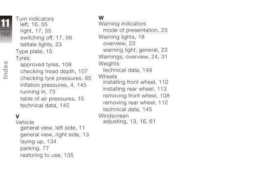
Turn indicatorsleft, 16, 55
right, 17, 55
switching off, 17, 56
telltale lights, 23
Type plate, 15
Tyres
approved tyres, 108
checking tread depth, 107
checking tyre pressures, 65
inflation pressures, 4, 145
running in, 73
table of air pressures, 15
technical data, 145
VVehicle
general view, left side, 11
general view, right side, 13
laying up, 134
parking, 77
restoring to use, 135
WWarning indicators
mode of presentation, 23
Warning lights, 18
overview, 23
warning light, general, 23
Warnings, overview, 24, 31
Weights
technical data, 149
Wheelsinstalling front wheel, 110
installing rear wheel, 113
removing front wheel, 108
removing rear wheel, 112
technical data, 145
Windscreenadjusting, 13, 16, 61
11166
z Ind
ex

Details described or illus-
trated in this booklet may
differ from the motorcycle's
actual specification as pur-
chased, the accessories fit-
ted or the national-market
specification. No claims will
be entertained as a result of
such discrepancies.
Dimensions, weights, fuel
consumption and perform-
ance data are quoted to the
customary tolerances.
The right to modify designs,
equipment and accessories is
reserved.
Errors and omissions excep-
ted.
© 2005 BMW Motorrad
Not to be reproduced either
wholly or in part without writ-
ten permission from BMW
Motorrad, After Sales.
Printed in Germany.

Important data for refuelling.
FuelRecommended fuel grade Super Plus (premium), un-
leaded98 ROZ
Fuel grade, usable with power- and consumption-related restrictions Regular, unleaded91 ROZ
Usable fuel capacity 27 l
Reserve fuel 4 l
Tyre pressuresFront wheel, tyre pressure, one-up 2.2 bar, tyre cold
Rear wheel, tyre pressure, one-up 2.5 bar, tyre cold
Front wheel, tyre pressure, two-up or luggage 2.5 bar, tyre cold
Rear wheel, tyre pressure, two-up or luggage 2.9 bar, tyre cold
Front wheel, tyre pressure, two-up and luggage 2.5 bar, tyre cold
Rear wheel, tyre pressure, two-up and luggage 2.9 bar, tyre cold
BMW recommends
BMW Motorrad
Order No.01 41 7 698 85108.20052. Issue The Ultimate Riding
Machine

E1
BM
W M
oto
rrad
In
teg
ral A
BS
About BMW Motorrad Integral ABS
How does ABS work?The maximum braking force it is possible to transfer to the carriageway depends, among other things, on the road surface's coefficient of friction. Gravel, ice and snow, and water on the road, have significantly poorer coeffi-cients of friction than a dry, clean asphalt road surface. The poorer the road's coeffi-cient of friction, the longer the braking distance.If the maximum braking force it is possible to apply to the road is exceeded when the rider increases brake pressure, the wheels will begin to lock and directional stability is lost; a fall threatens. Before this situation can arise, ABS intervenes and
adapts the braking pressure to the maximum braking force it is possible to transfer so that the wheels continue to turn and driving stability is main-tained whatever the prevailing road conditions.
What happens with bumps in the road?Corrugated road surfaces or bumps in the road can cause the tyres to temporarily lose contact with the road surface and hence the braking force it is possible to apply to drop to zero. If the brakes are applied in this situation, the ABS must reduce the braking pressure to ensure driving stability when contact with the road surface is restored. At this moment, BMW Motorrad Integral ABS
must assume extremely low coefficients of friction (gravel, ice, snow) so that the wheels turn in any conceivable situa-tion and thus the stability of the motorcycle is ensured. Once the actual circum-stances are detected, the system will set the brake pres-sure to the optimum value.
What do we observe during rider safety training?Braking in which ABS has to intervene has, by comparison with normal braking, a signifi-cantly higher demand for electricity which puts a heavy load on the battery. The battery is constantly being charged in normal riding so that it always has sufficient capacity available.
Info_I_ABS_en_xx.fm Seite 1 Dienstag, 19. Juli 2005 2:48 14

BM
W M
oto
rrad
In
teg
ral A
BS
E2
If the motorcycle is not to be ridden for several weeks, a trickle charger, which can be obtained from your BMW Motorrad dealer, should be connected or the battery disconnected and then recharged before starting riding again. During rider safety training, an unusual number of ABS-controlled braking operations take place in rapid succession interspersed with periods of waiting and assessment in which the motorcycle is not being ridden. The battery is put under heavy load by the ABS control actions, but at the same time it is not being recharged as practically no riding is being done. In isolated cases, in this artificially created situation,
braking operations in which the brake lever is operated with maximum force and extreme speed, in combina-tion with declining on-board supply voltage, can bring the ABS up to its technical limits in which its control function is no longer fulfilled. Field observations carried out by BMW Motorrad indicate that a comparable situation has not arisen in traffic or even during training rides.The following notes must be observed during safety training:• check the warning and
indicator lamps before any braking exercise
• ride the motorcycle over sufficient distance to charge the battery after a maximum of five braking exercises
• switch off consumers such as seat and grip heating, radio, navigation system and accessories connected to the power sockets
• in pauses and discussions, switch off the ignition; if the engine is switched off with the emergency off switch, the lights and all electronic systems remain switched on and drain the battery
How can I achieve the shortest braking distance?Dynamic load distribution between the front and rear wheels changes under braking. The heavier the brakes are applied, the more load is transferred to the front brake. The greater the load on the wheel, the more braking force can be transferred.
Info_I_ABS_en_xx.fm Seite 2 Dienstag, 19. Juli 2005 2:48 14
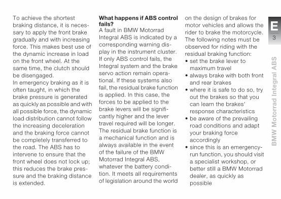
E3
BM
W M
oto
rrad
In
teg
ral A
BS
To achieve the shortest braking distance, it is neces-sary to apply the front brake gradually and with increasing force. This makes best use of the dynamic increase in load on the front wheel. At the same time, the clutch should be disengaged. In emergency braking as it is often taught, in which the brake pressure is generated as quickly as possible and with all possible force, the dynamic load distribution cannot follow the increasing deceleration and the braking force cannot be completely transferred to the road. The ABS has to intervene to ensure that the front wheel does not lock up; this reduces the brake pres-sure and the braking distance is extended.
What happens if ABS control fails?A fault in BMW Motorrad Integral ABS is indicated by a corresponding warning dis-play in the instrument cluster.If only ABS control fails, the Integral system and the brake servo action remain opera-tional. If these systems also fail, the residual brake function is applied. In this case, the forces to be applied to the brake levers will be signifi-cantly higher and the lever travel required will be longer. The residual brake function is a mechanical function and is always available in the event of the failure of the BMW Motorrad Integral ABS, whatever the battery condi-tion. It meets all requirements of legislation around the world
on the design of brakes for motor vehicles and allows the rider to brake the motorcycle. The following notes must be observed for riding with the residual braking function:• set the brake lever to
maximum travel• always brake with both front
and rear brakes• where it is safe to do so, try
out the brakes so that you can learn the brakes' response characteristics
• be aware of the prevailing road conditions and adapt your braking force accordingly
• since this is an emergency-run function, you should visit a specialist workshop, or better still a BMW Motorrad dealer, as quickly as possible
Info_I_ABS_en_xx.fm Seite 3 Dienstag, 19. Juli 2005 2:48 14

BM
W M
oto
rrad
In
teg
ral A
BS
E4
What is the role of regular maintenance?
Any technical system is only ever as good as its
maintenance.The service intervals specified must be kept to without fail to ensure that the BMW Motorrad Integral ABS is in an optimum maintenance condition.
What is the design specification for BMW Motorrad Integral ABS?BMW Motorrad Integral ABS ensures stability of the motor-cycle on any surface within the bounds of physics. The system is not designed for special requirements such as those that arise under extreme conditions of competition off-road or on the racetrack.
��� ��������
��� ��� � �� � ��� ��� ��� ���� ������ ����� �� � ��!��
�����" ��#���
Info_I_ABS_en_xx.fm Seite 4 Freitag, 22. Juli 2005 10:17 10