rhinogold 4.0 training guide (may2013)
TRANSCRIPT

Training Guide MAY 2013

2 RhinoGold Training Guide
Welcome to RhinoGold 4.0 Training Guide
Thanks for download the new training guide! We hope you enjoy and learn with these new
tutorials step by step.
Doubts using the guide?
Support and training are available worldwide, even before you buy.
Forum: www.myRhinoGold.com
Email Support: [email protected]
Phone: +34 93 7547774 (CET)
About RhinoGold
By taking advantage the power of 3D CAD (Computer Aided Design) and making it jeweler-
friendly, RHINOGOLD lets you design 3D jewelry while generating a detailed color preview
image that can be printed or emailed as well as generating a full report of the piece.
RhinoGold is a 3D Jewelry design software to design jewelry in 3D and then, output the file,
compatible with any Printing Machine which generates dimensionally accurate models
ready for casting.
More information www.rhinogold.com
About TDM Solutions;
TDM Solutions is a company that provides CAD/CAM solutions to a variety of industries, focu-
sing in jewelry, and also including the automotive, casts and molds, prototype, footwear and
general mechanical industries. Developer of design and manufacturing applications, en-
hancing RhinoGold, and others as RhinoMold, RhinoNest, Clayoo and RhinoShoe.
TDM Solutions was founded in 2001 and the headquarters are in Barcelona, Spain.
Nowadays is working over 25 countries with more than 80 resellers.
More information www.tdmsolutions.com

3 RhinoGold Training Guide
1. RhinoGold Introduction 3. Modeling 33
1.1 Getting started with RhinoGold 7 3.1 Solids 34
1.2 Interface 8 3.2 Surfaces 36
1.3 Viewport toolbars 13 3.3 Loft Surface 38
1.4 Browser - Explorer 14 3.4 Sweep 1 and 2 Rails 39
1.5 Browser - Real time render 14 3.5 Extrude 40
1.6 Browser - Library 15 3.6 Revolve Surface 41
1.7 User Folder Manager 16 3.7 Revolve by Rail Surface 42
1.8 Inside Rhinoceros Interface 17 3.8 Network Surface 43
3.9 Boolean 44
2. Drawing 18 3.10 Fillet and Chamfer 44
2.1 Lines 19 3.11 Curve from Objects 45
2.2 Modeling Aids 19 3.12 Project Curves 47
2.3 Relative and Absolute coordinates 20 3.13 Intersect 47
2.4 Osnap 21 3.14 Duplicate Edge 47
2.5 Circle and Arc 22 3.15 Modify Surfaces 48
2.6 Smart Track 23 3.16 Blend Surfaces 49
2.7 Curve 24 3.17 Match Surfaces 50
2.8 Trim, Split and Curve Boolean 25 3.18 Offset surfaces 50
2.9 Fillet and Chamfer 27 3.19 Modify Solids 51
2.10 Extend curve 27 3.20 Auto Cut 53
2.11 Offset 28 3.21 Fill Solid 53
2.12 Editing Control Points 28
2.13 Match curve 29
2.14 Blend curve 30
2.15 CPlane 30
2.16 Text on Curve 32
Index

4 RhinoGold Training Guide
4. Transform 54 6. Jewellery Tools 79
4.1 Gumball Transformer 57 6.1 Ring Wizards 80
4.2 Scale by Dimensions 58 6.2 Signet Ring 82
4.3 Dynamic Polar Array 59 6.3 Ring by Curve 83
4.4 Dynamic Array 59 6.4 Ring by Objects 84
4.5 Symmetry 60 6.5 Gauge 86
4.6 Copy by Gems 61 6.6 Hollow Ring 87
4.7 Flow by Curve 63 6.7 Scale Ring 88
4.8 Flow by Surface 64 6.8 Dynamic Profile 89
4.9 Splop 65 6.9 Cutom Regions 91
4.10 Edit 66 6.10 Channel 92
4.11 Smart Flow by Curve 67 6.11 Cutter 93
6.12 Cutters In Line 94
6.13 Head Studio 95
6.14 Bezel Studio 96
6.15 Azure 97
5. Gems Tools 68 6.16 Prongs In Line 98
5.1 Gem Studio 69 6.17 Chain 99
5.2 Gem Creator 71
5.3 Gem Info 72
5.4 Gems by Curve 72 7. Artistics 100
5.5 Gems by 2 Curves 73 7.1 Raster to vector 101
5.6 Pave Automatic 74 7.2 Place Image 1:1 102
5.7 Pave UV 75 7.3 Heightfield 103
5.8 Pearls 77 7.4 Heightfield by colors 103
5.9 Cabochon 78 7.5 Texture 3D 104
7.6 Texture Creator 105
7.7 Celtic Knots 105
Index

5 RhinoGold Training Guide
8. Manufacturing 106
8.1 STL Wizard 107
8.2 Support 114
8.3 Milling Support Structures 115
8.4 Organize 115
8.5 3D Printers 116
9. Engraving 117
9.1 Line type and hatch 118
9.2 Nesting 119
9.3 Export SVG and HPGL 119
10. Animation and Render 120
10.1 Animation Studio 121
10.2 Set current Render 121
10.3 Render Studio 122
10.4 Scenarios 122
11. Analyse 123
11.1 Metal Weight 125
11.2 Report 126
11.3 Weight By Area 127
11.4 Material Selector 127
Index

6 RhinoGold Training Guide
Lesson 1 – Getting Started

7 RhinoGold Training Guide
Getting Started
After installing RhinoGold, the next icon will appear on the Desktop:
Clicking on the icon, the RhinoGold Welcome:

8 RhinoGold Training Guide
RhinoGold interface
Toolbar
View Title
Graphic Area
Tabs

9 RhinoGold Training Guide
Universal plane axes icon
Commands line
Status bar
Most of the RhinoGold commands can be found in the menus.
Start up RhinoGold in the standard toolbar attached to the top part of the graphic
area. More icons can be included in the menus.
Optional buttons
A button on the toolbar can include other buttons with commands in a toolbar with
optional buttons. As a rule the optional toolbars contain changes in the basic com-
mand. After selecting a button on the optional toolbar, the toolbar disappears.
The buttons on the optional toolbars have a small black triangle at the bottom of
them.
To open the optional toolbar, left click with the mouse on the small black triangle.
Example of an optional toolbar. After
opening the optional toolbar, select any
of the buttons on the toolbar to execute a
command.

10 RhinoGold Training Guide
Graphic area The RhinoGold graphic area can be customized to adapt it to your preferences.
The layout of the views can be configured in different ways.
Views
The views are windows in the RhinoGold graphic area that show different views of
the model. The size of the view can be moved or changed by dragging the bar of
the title or the edges. It is also possible to create new views, change the names of
the views and use predefined configurations. Each view has its own construction
drawing on which the cursor moves, and a planning mode.
By default, there are four views, but we can change it.
Enter commands Use the command line to enter commands, options, coordinates, distances, angles,
radius, abbreviated keyboard methods and to see the command requests.
To enter the data in the command line, press Enter, the space bar or right click with
the mouse on a view.
Note: The Enter key and the space bar exercise the same function in RhinoGold.
The abbreviated methods are combinations of customizable keys. You can program
the function keys and key combinations with Ctrl for executing RhinoGold com-
mands.

11 RhinoGold Training Guide
One-click options
To use the commands options, click on the commands lines or enter the underlined
letter of the option and press Enter. (The block capitals inside are not important).
Repeat commands
To repeat the last command, right click on a view or press Enter or the space bar. To
repeat previous commands, right click on the commands line window and select
the commands from the list.
Cancel commands
To cancel a command press Esc or enter a new command using a button or menu.
Self-completion of command names
Write the first letters of the command to activate the self-completion commands.
When enough letters of the command have been entered for it to be the only one,
the command name will be completed in the commands line. Press Enter to acti-
vate the command when the full command name appears. When entering the
command names, the list of self-completed commands will appear. As you write the
letters, the list will be reduced to the possible commands. Left click on the command
in the list to execute it.
Help
To execute the RhinoGold help function, go
at any time to the (?) icon and execute the
help function. It will open up and display
the RhinoGold commands. You can also
access the Rhino help for consulting infor-
mation about a specific command just by
pressing the command and then pressing
F1.

12 RhinoGold Training Guide
View the command line history
The command line history shows the last 500 lines of
the commands in the current RhinoGold sessions.
View recent commands
Right click on the commands line to see the most recent
commands. To repeat the command, select it in the pop-
up menu. The number of commands listed is defined in the
RhinoGold Options. The predefined limit is 20 commands.
Central button options
Click on the mouse central button and a functions window will pop up, divided up
into 2 blocks. Selection tools.

13 RhinoGold Training Guide
Zoom
Extens zoom: This activates a zoom that will zoom all the objects
drawn on the plane.
Window zoom: you can perform the zoom through a window.
Zoom 1:1: This generates a zoom that automatically activates it to
the real scale.
Undo zoom: Get back to the previous view
Selected zoom: this creates a zoom through a selection of elements.
Place target: Can be defined a point to centre the zoom
Rotate view: This dynamically rotates the views, and has the same
function as the right hand button of the mouse.
Zoom In Out: Control the zoom dynamically with the mouse.
Pan: Drag with the mouse.
Display Mode
1. Wireframe
2. Shaded
3. Rendered
4. Rendered Shadow
5. Ghosted
6. Technical
7. Pen
8. STL Repair
9. Neon
Visibility Manager (press SHIFT key to show)
1. Hide
2. Show
3. Show selected
4. Invert selected and hide
5. Swap hidden and visible
6. Lock
7. Unlock
8. Unlock selected
9. Invert Selection and lock

14 RhinoGold Training Guide
Browser: Explorer
The main function is to show all the parametrical
and editable objects of our document. As keep
creating, automatically objects will be added.
All objects are group by type, and for gems, also
in dimensions. The main function is to select ob-
jects and edit them.
Important Points
1. We cannot select objects of different types to
edit at the same time. However, you can select
objects of the same type as much as you want
to.
2. The predominant object is the Gem. It means
that when we create a Bezel, Head, prongs, cut-
ters,...they all know in which gem they belong in.
All properties belong to objects, it allows us to
create Components Library, and use it in several
designs without losing properties. In other words,
if we like a Bezel, is not necessary to be saved
with some types of gems and different sizes. Just
with one, we can edit the gem in the future,
keeping dimensions, angles, thickness,... You can EDIT!!
Browser: Real time Render
Includes a library of materials, divided in: Met-
als, gems, glass, pearls, plastic and wood. Also
includes the possibility to create our own mate-
rials easily. Easy to use, simply select the ob-
jects and click on the material to apply on. Im-
mediately it appears. Materials as well as the
scene are saved automatically on our file, and
it allows exporting images to standard formats
as JPG, BMP, TIFF, … as well as capturing those
images to paste them on any Windows appli-
cation like Microsoft Word, PowerPoint,…or di-
rectly to your email software.

15 RhinoGold Training Guide
How can I add my own materials?
1. Right click on the materials browser.
2. Choose the option: add new material.
3. Define the material proprieties.
To apply the materials, select the object or objects
and click on the material.
In the Render tab, we can add scenarios for render.
In Capture Viewport, we can create an
image file or a copy to Clipboard.
Browser: Library
Library allows us to manage our models easily.
The user may create his own libraries of compo-
nents, to may reuse in future designs.
Is faster and more agile to navigate from the lat-
eral window. It allows us to move folder to folder
of our Library, and insert our models in just one
click.
Important
Objects are added to the Browser automatically
and they are editable. Don’t keep thousand of
files, just edit it! You can EDIT them.

16 RhinoGold Training Guide
User Folder Manager
It allows us to define several parameters to adapt RhinoGold functionalities to our
needs or experiences.
The user folder is a folder where you save the RhinoGold files customized by the user
and customized region, Libraries curves, Gems, ... You can open this folder, inside File
menu > Options > User Folder Manager or from the RhinoGold menu in Rhino mode.

17 RhinoGold Training Guide
Where is my User folder?
By default, this folder is created in the folder of Roaming user: C:/Users/Username/
AppData/Roaming/TDMSolutions/RhinoGold/4.0
Rhinoceros Interface
How I can show the RhinoGold toolbar?
Type ShowToolbar in the commands line, then, type the toolbar name: RhinoGold.
Are compatible the files create in RhinoGold mode in Rhino?
It absolutely does! In both directions, RhinoGold works with 3DM format as Rhino,
and also is possible copy-paste models from both applications.

18 RhinoGold Training Guide
Lesson 2 – Drawing

19 RhinoGold Training Guide
Drawing Tools
Drawing lines I
The Line, Line: from midpoint and Polyline com-
mands draw straight lines. The Line from the
midpoint command draws only a line segment. The
Line: From the Midpoint command draws several li-
ne segments from one end to the other. The Polyline
command draws several straight segments joined
together (a single lineal curve with several seg-
ments).
Modeling Aids
The modes are modelling aids that can be activated or deactivated simply by pres-
sing an abbreviate method key, entering a letter or pressing a button.
Click on the Snap, Ortho and Planar or record history boxes on the status bar to acti-
vate and deactivate these modelling aids.
Grid Snap
This forces the cursor to move over the intersections of the grid.
You can also active / deactivate Snap by pressing F9 or entering the letter S and
pressing Enter.
Ortho
This restricts the movement of the cursor at the points in a specific angle from the last
point created. The predefined angle is 90 degrees.
You can also activate / deactivate the Ortho mode by pressing F8.

20 RhinoGold Training Guide
Planar
This modelling aid is similar to the Ortho mode. It facilitates the modelling of flat ob-
jects by forcing a plane parallel to the construction plane that passes through the
last point selected.
You can also activate / deactivate the Planar mode by entering the letter P and
pressing Enter.
Record History
This saves the historic record and updates the objects with the historic record. With
the historic record saving and updating options activated, a transition surface can
be changed by editing the entrance curves.
Relative coordinates
The absolute coordinates may be slow and uncomfortable but they work very well.
In most cases the relative coordinates are easier to use.
Every time you select a point RhinoGold saves that point as the last point.
Relative coordinates are based on the last point and not on the point of origin (0,0,0)
of the construction plane.
To work with relative coordinates, the X, Y and Z coordinates must be preceded by
an R.
Absolute coordinates
The first type of coordinate used is called an absolute coordinate. Absolute coordi-
nates are exact points on the X, Y and Z axes.

21 RhinoGold Training Guide
Exercise:
Create a shape for these figures with coordinates.
Starting Point
Optional exercise:
Object Snap (Osnap)
There are several options which can be activated or not by using the checkbox.

22 RhinoGold Training Guide
Command Button Description
End Restricts the cursor at the end of a curve, the corner of a surface
edge or the end of a polyline segment. Near Restricts the cursor to the point nearest an existing curve.
Point Restricts the cursor to a control point.
Med Restricts the cursor to the midpoint of a curve or surface edge.
Cen Restricts the cursor to a point at the centre of a curve. This works bet-
ter with circles and arches. Int Restricts the cursor to a point at the intersection of two curves.
Perp Restricts the cursor to a point on the curve that perpendicular to the
last point selected. It does not work on the first point that a command re-
Tan Restricts the cursor to a point on a curve that is tangential to the last
point selected. It does not work on the first point that a command
Quad Restricts the cursor to the quadrant point. The quadrant point is the maxi-
mum or minimum direction of a curve in the X or Y direction of the construc-
Knot Restricts the cursor to control points in curves or surface edges.
Plan Projects the selection point to the construction plane.
SmartTrack SmartTrack is a system of temporary lines and points of reference that
are drawn in the Rhino view using implicit ratios between different 3D
points, another spatial geometry and the directions of the coordinate
axes.
Deactivate Temporarily deactivates the references to permanent objects, saving
Optional Exercise:

23 RhinoGold Training Guide
Arc - Exercise:
Create the following figure with Lines and Arcs.
After creating the figure, create the axis, as
shown in the drawing, create a revolution.
The Revolve command is in the Modelling tab.
Smart Track
SmartTrack™ is a system of temporary lines and points of reference that are drawn in the
RhinoGold view using implicit ratios between different 3D points, another spatial geometry
and the directions of the coordinate axes.
The temporary infinite lines (dragging lines) and points (intelligent points) are available for
references to objects as if they were real lines and points. It can restrict the cursor to inter-
sections of dragging lines, perpendicular lines and directly to the intelligent points, as well as
the intersections of dragging lines and real curves. The tracking lines and intelligent points
are shown during the command.
It can add or “capture” new points as necessary, up to the current maximum. When the
maximum is reached, the oldest intelligent points disappear and new ones are added. The
intelligent points captured can be erased at any time if they are not useful.

24 RhinoGold Training Guide
Curve
Command Description
Curve Creates a curve that passes through specific
interpolated points. These points remain on the
curve and determine its curvature.
Curve by CP A curve by means of control points creates a
curve with specified control points. The control
points are not on the curve but they determine its
curvature. Interpolate on Surface Draws a curve through selected locations on a sur-
face. Sketch Draws a curve by dragging the mouse. Sketch on Surface Sketches a curve on a surface. Sketch on Polygon Mesh Sketches a curve on a polygon mesh. Helix Draws a helical curve. Spiral Draws a spiral curve Average 2 Curves Makes a curve half-way between two input curves. Conic Draws a conic section curve. Handle Curve Draws illustration-program-style chained Bézier cur-
ves. Curve: Control Points
from Polyline The curve's control points are placed at the vertices
of the polyline Curve: Through Polyline
Vertices The curve passes through the vertices of the polyli-
ne.
Lines to Arcs Convert curves into arcs
Exercise:
Create a primitive shape with the polyline to create the heart base. Once the base
has been created, which is the polyline, create the curves, as shown in the image,
with the aid of Osnap.
When the curves of the heart have been created, hide the original polyline created
at the start.

25 RhinoGold Training Guide
Exercise:
1. Open the Trace.3dm file.
2. Plot the course of a Curve interpolated by points, following the
image of the eye.
3. Extrude the curve after plotting it.

26 RhinoGold Training Guide
Trim and Split
This command cuts and erases parts of an object to make it end
exactly at the intersection.
Exercise:
Open the Trim and Split.3dm file of the RhinoGold models.
Trim Split
Curve Boolean
This command joins the parts of an object to make it end in the exact shape you
want.
Exercise:
Open the Boolean curve.3dm file of the RhinoGold models.
1. Select the Boolean curve command in the Drawing tab.
2. The commands line will ask you to select all the curves. You can select DeleteIn-
put=All to delete the curves after use it.

27 RhinoGold Training Guide
3. Select the areas to create a new curve.
Fillet and Chamfer
This command connects two lines, arcs, circles or curves by extending or
shortening them so that they touch each other or are joined with a circular
arc.
Exercise:
Open the Fillet and Chamfer.3dm file of the RhinoGold models.
Extend curves
The Extend command lengthens an object to make it end precisely at the intersec-
tion with another object. It is also possible to lengthen an object, even if there is no
intersection.
Exercise:
Open the Extend curve.3dm file of the RhinoGold models.
Please try the four types: Natu-
ral, Line, Arc and Smooth. And
take a look to Point and Cen-
ter option!

28 RhinoGold Training Guide
Offset
The Offset command creates an object that is parallel or concentric with
another object. Offset is used to create special copies such as parallel lines,
concentric circles and concentric arcs through specific points or
at predefined distances.
Exercise:
Open the Offset in-out.3dm file of the RhinoGold models.
1. Offset the central figures of the rectangle, the offset allows you to offset all the
curves at one time.
2. After creating the offset execute the Trim command to leave the element ready.
Starting Drawing
End Drawing
Editing Control Points
The control points or editing points of an object can be viewed to adjust the
shape of the object instead of having to manipulate the whole object. This is
called editing control points.
The points can be edited in meshes, curve and surfaces but not on polysurfaces or
solids.
The RhinoGold curves are shown internally through rational non-uniform B-splines
(NURBS). The shape of a NURBS curve is determined by three factors:
•A list of points known as control points
•Degree
•A list of numbers known as nodes
If any of these elements is modified, the shape of the curve will be changed.

29 RhinoGold Training Guide
Observations on the control points, editing points and nodes
•The control points do not have to be on the curve.
•The editing points are always on the curve.
•RhinoGold allows you to edit curves and surfaces by moving the control and edi-
ting points.
•The nodes are parameters (i.e., numbers and not points).
•Adding nodes to a curve or surface allows you to control the movement of the ob-
ject while editing the control points.
Exercise:
Open the Edit control points.3dm file of the RhinoGold
models. Adjust the curve in black and adapt it to the
red curve, using the control points. The control points
are activated in the Drawing tab, in the Edit Pt sub-
menu. After adapting the curve, the next step is to hide
the red curve with the central hide button
The other part of the exercise is optional, since the in-
structions will be brief: How to create the ring: Create a
Network surface using the Network in the Modeling tab, in
the Loft sub-menu.Create a caliber with the cylinder. Per-
form the Boolean Difference operation.
Match
This command allows you to make on curve equal to another, joining them
by searching for the position, tangency or curvature of the curves.
Exercise:
Open the Match curves.3dm file of the RhinoGold models . Please see the differen-
ce between the position, tangency and curvature.

30 RhinoGold Training Guide
Blend Curve and Blend Adjustable
Creates a blend curve between curves and/or surface edges with
control over the blend continuity.
Exercise:
Open the Blend curves.3dm file of the RhinoGold models . Please see the difference
between the position, tangency and curvature. The difference between commands
is the Adjuntable allows to draw and drop the points.
CPlane
The CPlane is a grid of the construction plane where you will create all your
elements, and can even change their location on the axes.
Exercise:
Open the CPlane.3dm file of the RhinoGold models.
1. On the Drawing tab, click on CPlane Set.
2. There are several options between brackets for selecting the
way to position the CPlane. Select Object option and click on the
top surface.
3. The CPlane will be placed at the top of the ring thereby enabling
you to work on this part of the ring, like the example shown in the
images, with the curved tool, for example.
4. Create Text is in the Drawing tab, when creating the text create it
in Curves and position it using the Move, Rotate and
2D scale tools until it looks like the one in the image.
5. Create an extrusion of the curve created and the letters in nega-
tive, at a distance of -0.5. In Modeling tab, there is the Extrude com-
mand:

31 RhinoGold Training Guide
6. In the Modeling tab of the Boolean Difference Union sub-
menu. In the case of the Boolean tool first select the group
that will not be eliminated, in that case the group that will re-
main intact is the ring. As the second group, select the extru-
sion.
Lines to Arcs
Create Arcs from lines. It creates really interesting results.
Exercise:
Open the Lines to Arcs.3dm file.
1. Execute the command Lines to Arc and select the square.
2. Define Distance as 3.5. Click OK to accept.
3. Repeat the process but now we will use the value -1.

32 RhinoGold Training Guide
Text on Curve
This tool allows us to create 2D and 3D text on 2D and/or 3D curves.
1. Select the Curve on which you wish to create the
text.
2. Write the text to display in Text, we also can defi-
ne font type.
3. In Parameters we can define the size, justification,
position in relation to the curve, etc...
4. We also have the possibility of creating 3D text,
defining an extrusion value of extrusion, and well as
deciding if we want to apply this effect to both si-
des.
5. We can also define an angle for the text rotation.
6. Click on the checkbox to add the text to the do-
cument.
Exercise:
Open the Text on Curve.3dm file.
1. Execute the Text on Curve tool.
2. Select the curve to créate the text.
3. Define the Text and font.
4. Define the parameters.
5. Click on the Checkbox.

33 RhinoGold Training Guide
Lesson 3 – Modelling

34 RhinoGold Training Guide
Modelling Solids
It is easy to model solids in RhinoGold. There are several commands that allow you to
create and edit solid objects. Solids in RhinoGold are closed surfaces or polysurfaces
enclosing a volume.
Some of the original solids surfaces are simple closed surfaces whose edges coincide
completely, and others are polysurfaces.
The RhinoGold Polysurface objects can be deformed using the new UDT (Universal
Deformation Technology) tools. Surfaces can also be extracted and deformed by
editing the control points, as in the last exercise. This part of the course offers a de-
scription of how to create solids, separate parts, make changes and join parts to
make a solid.
Draws a rectangular box using the corners
Draws a rectangular box using two diagonal corners and a height.
Draws a box using two adjacent corners, a point on the edge at the
other side and a height.
Draws a rectilinear bounding box object (polyline or polysurface) that
encloses the objects.
Draws the minimum Bounding Box of one or several objects. This com-
mand has multiple applications, enhancing that one that searches the
best position to save materials in the prototyping.

35 RhinoGold Training Guide
Draws a sphere box using center point and the radius/diameter value.
Draws a sphere using the two ends of its diameter.
Draws a sphere using three points on the surface.
Draws the base circle through three points and uses a fourth
point to determine the sphere's size.
Draws a sphere perpendicular to a curve.
Draws a sphere tangent to three curves.
Draws a sphere by fitting to selected point objects.
Creates a solid ellipsoid with options for from the corners of a bounding box,
axis endpoints, from foci, and around a curve.
Draws an ellipse around a curve.from the diameter
Draws an ellipse from focus points and a point on the curve.
Draws an ellipsoid from the corners of an enclosing rectan-
gle.
Draws an ellipse around a curve.
Draws a solid cone
Draws a solid cone whose apex is truncated by a plane.
Draws a parabolic surface from the focus or vertex locations.
Draws a solid pyramid from a polygon base and a height.
Draws a solid cylinder
Draws a closed cylinder with a concentric cylindrical hole.
Draws a solid torus (donut shape).
Draws a surface with a circular profile around a curve.
Draws a surface with a circular profile around a curve. Cap with
hemispherical surface.
Draws a surface with a circular profile around multiple curves.

36 RhinoGold Training Guide
Exercise:
Save the file as Create Solid.3dm in the RhinoGold models, and try to model these
pictures. The sizes are not important. Remember the Osnap, it will helps you in this ex-
ercise. Concentrical trucated cones
Castle
Piramids on a cube
Modelling Surfaces
The surface modeling is one of the principal advantages of RhinoGold. These surfac-
es also known as NURBS, Non-Uniform Rational B-Splines, are mathematical represen-
tations of 3-D geometry that can accurately describe any shape from a simple 2-D
line, circle, arc, or curve to the most complex 3-D organic free-form surface or solid.
Because of their flexibility and accuracy, NURBS models can be used in any process
from illustration and animation to manufacturing.

37 RhinoGold Training Guide
Creates a surface from specified corner points.
Draws a rectangular planar NURBS surface from specified corner locations
Draws a rectangular planar NURBS using two adjacent corner locations
and a location on the opposite side.
Draws a rectangular planar NURBS perpendicular to the construction pla-
ne.
Creates a surface from specified corner points.
Fits a surface through selected curves and point objects.
Creates a planar surface from planar curves that define the surface
edges.
Creates a surface fit through selected profile curves that define the surface
shape.
Creates a surface from a network of curves.
Creates a surface through profile curves that define the surface shape and
one curve that defines a surface edge.
Allows to place profile curves along a rail curve.
Creates a surface through profile curves that define the surface shape and
two curves that define the surface edges.
Allows to place profile curves along rails curves.
Creates a surface by revolving a profile curve that defines the surface shape
around an axis.
Creates a surface by revolving a profile curve that defines the surfa-
ce shape around a rail curve that defines the surface edge.
Allows to pull or push a surface from a curve.

38 RhinoGold Training Guide
Creates a surface or solid by driving a curve in a straight line perpendicular to
the construction plane.
Extrudes a curve along a path curve.
Creates a surface or solid by driving a curve to a pointed surface.
Creates a surface or solid by extruding a curve to a tapered polysur-
face.
Creates a surface by offsetting a curve and creating a ruled surface
in the area between the two curves.
Creates a surface by extruding a curve on a surface, normal to the
surface.
Create solids and automatically remove the interior using only a closed curve.
All the measures can be defined in the parameters.
Creates a polysurface or solid by driving a surface in a straight line perpendi-
cular to the construction plane.
Extrudes a surface along a path curve.
Creates a surface or solid by driving a surface to a pointed surface.
Creates a surface or solid by extruding a surface to a tapered polysur-
face.
Offsets a curve, extrudes and caps the result to create a solid.
Extrudes closed planar curves normal to the curve plane toward a
boundary surface where the boundary surface is trimmed and joined
to the extruded objects.
Extrudes a curve in two directions to a boundary surface.
Loft Surface
Create a surface using shape curves; the normal, loose and adjusted
options create a surface without folds when it passes through curved
shapes.
The Straight sections option creates a surface with folds in each curved
shape and straight sections between the curved shapes.

39 RhinoGold Training Guide
Exercise:
Open the Loft.3dm file in the RhinoGold models.
Sweep 1 Rail
Creates a surface through profile curves that define the surface shape and
one curve that defines a surface edge.
Exercise:
Open the Sweep 1 rail.3dm file of the RhinoGold models.
1. On the Modeling menu, click on Sweep 1 rail.
2. First of all select the rail curve.
3. Select the 2 cross sections.
4. Press Enter key
5. A display window will apear with the Sweep
Options, define closed sweep and click OK.

40 RhinoGold Training Guide
Sweep 2 Rails
Create a surface using curved shapes that follow two paths defining the
edges of the surface.
Exercise:
Open the Sweep 2 rails.3dm file of the RhinoGold models.
1. On the Modeling tab, click on Sweep 2 rail.
2. Select the two blue rail curves.
3. Select the cross section curves. (black curves)
4. Press Enter.
5. In the Sweep 2 rail dialog, click on Accept. A surface will
be created in which the edges coincide with the
path curves.
Extrude
Extrude a curve (or more) perpendicular to the construction plane with the
option of tapering the surface with the de-molding angle.
Exercise:
Open the Extrusion.3dm file in the RhinoGold models.
1. On the Modeling tab, click on Extrude.
2. Select the curve freely.
3. Enter the value 1.3 in the command
line.
4. After creating the part, position the
gem in the middle of the element.

41 RhinoGold Training Guide
Revolve Surface
Revolves a curve around an axis to create a surface.
Exercise:
Open the Revolution.3dm file in the RhinoGold models.
4. Select the other end of the curve.
5. The command line will ask you for a revolution angle and a
series of options. Select FullCircle.
Practising surfaces
Exercise:
Open the Surfaces.3dm file of the RhinoGold models. In this exercise the aim is to
make different types of surfaces and execute the surfaces indicated in the same file.

42 RhinoGold Training Guide
Revolve by Rail
This revolves a curved figure by attaching an end along a
track. This command is useful for adding soft edges to irregular sur-
faces.
Exercise:
Open the Rail Revolve.3dm file of the RhinoGold models.
1. In the Modeling tab of the Revolve sub-menu, execute the Revolve Rail com-
mand.
2. Select the section curve.
3. Select the rail curve
4. Define the axis using the end points of the profile curve
5. Extrude the curve to the red curve:

43 RhinoGold Training Guide
6. Revolve by Rail the red curve. Remember you can use the extruded surface border as rail
Network Surface
The Network surface allows you to create a surface using curves or sections that are
joined together, i.e., touching each other, as these curves are not connected and
do not make up the surface; in the exercise one can see how a
Network surface is created from 5 curves.
Exercise:
Open the Network surface.3dm file of the RhinoGold
models.
1. In the Modeling tab, click on the Loft sub-menu and
then click on Network.
2. Select all the curves freely and press Enter.
3. On the Modeling tab, click on Offset.
4. Select the surface to be offset, the offset must
be at a distance of 0.5 towards the exterior and
with the option Solid in the command line activated.
5. On the Jewelry tab, click on Gauge
6. Select a European Region, size 14, and in the
cylinder field put the value 21 and click on OK
button.

44 RhinoGold Training Guide
7. In the Modeling tab, click on Boolean. 8. Click on Boolean Difference button 9. In First Group, click on Select button and select the ring solid 10. In Second Group, click on Select and select the cylinder
11. Click on Preview to see how will be the result
12. Click on the validation button to add the object to the document.
Exercise:
Please, open the file Boolean
Ring.3dm and test the Boolean
operations.
Variable Fillet and Variable Chamfer
Variable fillet and variable chamfer allows you to select edge in elements or surfac-
es that are joined to make a variable rounded shape with different specific radii that
are marked by you and in the case of a beveled edge, a distance marked by you.

45 RhinoGold Training Guide
Exercise:
Open the Fillet and Chamfer 3D.3dm file of the RhinoGold models.
1. In the Modeling tab, click on the Fillet sub-menu and then click on Variable fillet.
2. Select the outer edge of the silver element to create the joining radius with value
3 mm.
3. Select the outer edge of the gold element and proceed in the same way but with
a Chamfer edge of 2 mm.
Curves from Objects
These tools allow to create curves from a surface and solids. Tools as Intersect, Pro-
ject, Section, Duplicate border are really used each day for the modelers.

46 RhinoGold Training Guide
Creates curves or points on a surface that are the intersections of the surface
and curves or points projected toward the construction plane.
Creates curves and points on a surface that are the intersections of curve
or points pulled toward a surface in the surface normal direction.
Draws a curve that blends between two curves keeping continuity with
the curves.
Creates a curve that duplicates a surface edge.
Creates a curve that duplicates a surface, polysurface, or mesh
border.
Creates curves that duplicate surface isoparametric curves at
specified locations on the surface.
Creates curves that duplicate surface or polysurface isopara-
metric curves displayed in the wireframe view.
Create a center curve from a pipe.
Creates a curve that duplicates a polysurface face border.
Creates outline curves from a selected surface or polysurface.
Creates curves that duplicate the untrimmed boundary and trim
curves of a surface as planar curves onto the world x-y plane.
Wraps a curve onto a surface.
Creates point objects or curves at the intersection of curves and surfaces.
Creates point objects or curves at the intersection of objects
Creates a planar curve or points resulting from the intersection of a defined
cutting plane through curves, surfaces, polysurfaces, or meshes.
Creates a spaced series of planar curves and points resulting from the inter-
section of a defined cutting planes through curves, surfaces, polysurfaces, or
meshes.
Creates the middle curve on surface between two curves on surface
47 RhinoGold Training Guide
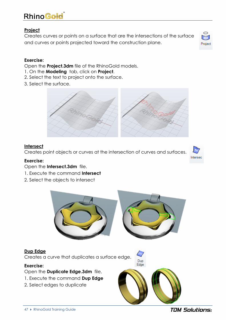
Project
Creates curves or points on a surface that are the intersections of the surface
and curves or points projected toward the construction plane.
Exercise:
Open the Project.3dm file of the RhinoGold models.
1. On the Modeling tab, click on Project.
2. Select the text to project onto the surface.
3. Select the surface.
Intersect
Creates point objects or curves at the intersection of curves and surfaces.
Exercise:
Open the Intersect.3dm file.
1. Execute the command Intersect
2. Select the objects to intersect
Dup Edge
Creates a curve that duplicates a surface edge.
Exercise:
Open the Duplicate Edge.3dm file,
1. Execute the command Dup Edge
2. Select edges to duplicate

48 RhinoGold Training Guide
Modify Surfaces
Extends the surface smoothly curving from the edge.
Extends surface edges to meet and trims the surfaces to each
other.
Creates a tangent surface between two surface edges with constant radius
profile and extends or trims the original surfaces to it.
Copies a surface so that locations on the copied surface are the same speci-
fied distance from the original surface.
Copies a surface so that all locations at the corners of the co-
pied surface are specified distances from the original surface.
Copies a curve on a surface in the normal direction of the sur-
face so that all locations on the copied curve are a specified
distance from the original curve.
Copies a curve on a surface so that all locations on the co-
pied curve are a specified distance from the original curve
and lie on the surface.

49 RhinoGold Training Guide
Places a ruled surface as a bevel between two surface edges.
Creates a tangent surface between multiple polysurface edges
with varying radius values, trims the original faces, and joins the fillet
surfaces to them.
Creates a ruled surface between multiple polysurface edges with
varying chamfer distances, trims the original faces, and joins the
chamfer surfaces to them.
Creates a continuous blend surface between two surfaces.
Adjusts the edge of a surface to have position, tangent, or curva-
ture continuity with another surface.
Combines two surfaces into one surface at untrimmed edges.
Sets an untrimmed surface edge tangent direction.
Mirrors curves and surfaces, makes the mirrored half tangent to the
original, and then when the original object is edited, the mirrored
half updates to match the original.
Creates intermediate surfaces between two input surfaces.
Removes trims and surfaces joined at the trim curves from a surface.
Contracts the underlying untrimmed surface close to trimming
boundaries.
Blend Surfaces
Blend surfaces allows you to create an intermediate surface be-
tween 2 surfaces, and play with the continuity.
Exercise:
Open the Blend Surfaces.3dm file of the RhinoGold models.To create the combina-
tion surface between the body and handle:
1. In the Modeling tab, click on the Fillet sub-menu and then click on Blend surface.
2. Select the edge of the handle.
3. Select the edge of the body.
4. In the command prompt: Adjust curve seams, Press Enter.
5. In the command prompt, select Continuity 1 = G2 Continuity 2 = G2
6. Click OK in the dialog.

50 RhinoGold Training Guide
Match Surface
Match is a tool used for joining open edges, either in a tangency position
or curvature.
Exercise:
Open the Match surfaces.3dm file of the RhinoGold models. Try the three possibilities:
Offset
Offset means creating an equidistant from the surface to a specific distance
that is marked.
Variable offset also exists, which performs the same function but the distance
of the equidistance can be increased or reduced at the required points.
Exercise:
Open the Offset surface.3dm file in the RhinoGold models.
1. Execute the Revolve command using the curve and axis.
2. After creating the surface perform the Offset at a distance of 0.5 mm in Solid.
With the option Solid in the commands line, if executing shift, the walls of the ele-
ment with which it will form a sold are also created.

51 RhinoGold Training Guide
Modify Solids
Allows us to create boolean operations of Union,
Difference, Intersection and Split.
Trims the shared areas of selected polysurfaces or surfaces and cre-
ates a single polysurface from the unshared areas.
Trims the shared areas of selected polysurfaces or surfaces with an-
other set of polysurfaces or surfaces.
Trims the unshared areas of selected polysurfaces or surfaces.
Splits shared areas of selected polysurfaces or surfaces and creates
separate polysurfaces from the shared and unshared parts.
Allows to move at random one or more objects. This tool solves ca-
ses that Boolean tool fails.
Cut solids and surfaces from the planar curves, following their own directions

52 RhinoGold Training Guide
Cut solids and surfaces from the planar curves, following their own
directions and keeping bothe sides as two different solids.
Fill solids and surfaces
Capping surfaces appear on planar holes of the objects.
Allows to create a rounded cap from closed planar curves.
Creates a closed polysurface from selected surfaces and polysurfaces
that bound a region in space.
Separates or copies a surface or a copy of a surface from a polysurfa-
ce.
Creates a hollowed out shell from a solid.
Combines all co-planar polysurface faces that share at least one edge in-
to one surface.
Combines two co-planar surfaces in a polysurface into one sur-
face.
Creates circular holes in surfaces or polysurfaces.
Trims a polysurface with a curve similar to cutting foam
with a heated wire.
Moves a polysurface face.
Creates a solid by driving a surface in a straight line.
Rotates a polysurface face around an axis.
Moves a polysurface edge.
Changes the length of planar surface or polysurface face
edges.
Rotates edges of a surface or polysurface around a center axis.
Divides a planar face of a polysurface with line or an exis-
ting curve.
Rotates selected polysurface faces around an axis line.
Split polysurfaces by selecting the edges to unjoin.

53 RhinoGold Training Guide
AutoCut
Cut solids and surfaces from the planar curves, following their own directions.
Exercise:
Open the AutoCut.3dm file,
1. Execute the command AutoCut
2. Select the planar curves and press Enter
3. Select the ring solid and press Enter
Fill Solid
Fill the holes of the solids.
Exercise:
Open the Fill Solid.3dm file,
1. Execute the command Fill Solid
2. Select the holes to fill
Wire Cut
Trims a polysurface with a curve similar to cutting foam with a heated
wire.
Exercise:
Open the Wire Cut.3dm file,
1. Execute the command Wire cut
2. Select one of the curves and
select the solid:
3. Select first cut depth point, and the second depth point:
4. KeepAll=Yes and repeat the same process using the second curve

54 RhinoGold Training Guide
Lesson 4 – Transform

55 RhinoGold Training Guide
Moves objects from one specified location to another.
Move objects following the normal of a surface.
Move objects following a surface orientation.
Move object in radial mode.
Moves objects relative to a center of move with a falloff
curve.
Makes duplicates of the selected objects.
Copy any object from a gem to others. It's really helpful.
Changes the size of selected objects uniformly in the x-, y-, and z-directions.
Scale several objects from the center.
Changes the size of selected objects in two directions.
Changes the size of selected objects in one direction.
Scale several objects in 1D. This direction defines the normal one
of a surface.
Changes the size of selected objects in three directions using different
lengths for each direction.
Allows scaling objects by weight. It allows us to adapt a design in a spe-
cific weight.
Scale objects by dimension. / Scale objects based on a plane.

56 RhinoGold Training Guide
Creates a mirror-image copy of objects.
Create the symmetry according the Y axe (green).
Create the symmetry according to X axe (red).
Create a symmetry according with the axes of CPlane.
Rotates objects around an axis perpendicular to the current construction pla-
ne.
Rotates objects around a specified axis in 3-D space.
Moves or copies, rotates, and scales objects using two reference and two tar-
get points.
Moves or copies and rotates objects using three reference
and three target points.
Moves or copies, rotates, and scales objects on a surface
Moves or copies, rotates, and scales objects on other object
Moves or copies and rotates objects along a curve using the
curve direction for orientation.
Copies and aligns a curve to a surface edge.
Lines up object's bounding boxes at their bottom, horizontal center, left, right,
top, or vertical center.
Move one or several objects to the center of CPlane
Allows moving, scaling and rotating objects by dynamical form, offering us
an interesting touch of the deformities.

57 RhinoGold Training Guide
Array tools
Lays out copies of objects in a specified number rows and columns.
Lays out copies of objects spaced and rotated along a curve.
Lays out copies of objects spaced between two points.
Lays out copies of objects in a specified number rows and columns
on a surface, using the surface normal to orient the objects.
Lays out copies of objects spaced and rotated along a curve on a
surface using the surface normal to determine the orientation of
the arrayed objects.
Copy in a polar form one or several objects. The copy direction it's defined
by the CPlane of the active view.
Lays out copies of objects in a circle around a central point.
Copy one or several objects in a really powerful and controlled way.
Exercise:
Open the Gumball transformer. 3dm file.
1. Execute the command Gumball Transformer, and select the middle
gem and bezel.
2. Change to the Front View to work easily.
3. Drag and drop the gem using the blue arrow

58 RhinoGold Training Guide
4. Now, repeat the process with the others gems and bezels.
Remember you can use the
Green Arc to rotate it.
5. Use Gauge command in Jewelry tab, and create a
cylinder European 15. We will use it to do the Boolean
Difference and remove the bottom part of the bezels.
Additional note: If you move just the gem, RhinoGold will
detect the bezel and will move it too.
Exercise:
Open the Scale by Dimension.3dm file.
1. Execute the command Scale by Dimensions in the sub-menu Scale and select
the object.
2. Define the new values for X, Y, Z as the image.
3. Click on the checkbox to approve the changes.

59 RhinoGold Training Guide
Exercise:
Open the Dynamic Polar Array.3dm file.
1. Execute the command Dynamic Polar Array and click on
Select button and select the gem and the bezel.
2. In Number of Copies, type the value 13. You can use the
mouse wheel to see the different results.
3. In Angle to fill, you can modify it to 360.
4. Click on OK button.
As option, you can create a cylinder using Gauge
to remove the bottom part of the bezels.
Exercise:
Open the Dynamic Array.3dm file.
1. Execute the command Dynamic Array.
2. Click on Object selector and select the Princess
gem, then click on Curve selector and select the
red curve:
3. In Parameters, in Number of Copies define 4 and
Distance between Objects 0.4, click on Center icon
and, click on Align Top icon. Press Shift and rotate
the Gumball to adjust the gem position.
4. Click on OK button.

60 RhinoGold Training Guide
5. Execute the command Dynamic Array again, now we will work on the side.
As Object select the brilliant, as
Curve, the black curve and click
on Surface selector and click the
side surface to orient the stones.
6. In Parameters, in Number of Copies define 7 and Distance between Objects 0.40,
in vertical align, click on Align Top icon.
7. In Increase Objects Gradient Mode, define the increments :0.2 in X, 0.2 in Y and 0.1 in Z
8. Click on the validation button.
Symmetry Commands
These commands allow to do a symmetry just clicking a button. Select the object
and click the icon.
One of the advantage of this tool is that can be used as a
Record. It allows us to modify the copied object at any time.
To Save Record, right click on Save Record, and activate the
first two options.

61 RhinoGold Training Guide
Exercise:
Open the Copy by Gems.3dm file. The objective is place the prongs in all gems.
1. Activate Always Record History and Update Children.
2. Execute the command Copy by Gems.
2. Select the origin gem.
3. Select the target gems.
4. Select the prongs to copy.
5. Take a look. The prongs are too much high. Please use the Gumball transformer to
move the original prongs a little bit down, and all the design will be updated.
As optional, you can create the prongs and do the Boolean Union!

62 RhinoGold Training Guide
Deformation tolos
Deforms objects by rotating the object around an axis.
Deforms objects by bending along a spine arc.
Deforms an object by moving its control points toward a specified axis.
Deforms an object by shifting it at a specified angle parallel to the construction
plane.
Averages the positions of curve and surface control points and mesh vertices
in a specified region.
Re-aligns an object or group of objects from a base curve to a target curve.
Morphs objects from a source surface to a target surface.
Copies, rotates, scales, and wraps objects on a surface, like pottery sprigging
or appliqué.
Deforms objects in a spiral as if they were caught in a whirlpool.
Deforms an object by scaling selected portions in one direction.
Deforms complex object smoothly using one-, two-, and three-dimensional
cages with simple control point structures.
Selects captive objects set up using the CageEdit command.
Selects control objects set up using the CageEdit command.

63 RhinoGold Training Guide
Removes selected objects from the influence of a control object set up by the
CageEdit command.
Allows to flow objects on a curve choosing the ones to de-
form and the ones to keep rigid.
Flattens a surface without restriction to single-directional curvature.
Exercise:
Open the Flow by Curve.3dm file. The objective of this exercise is deform an
object from a curve to other.
1. Activate Always Record History and Update Children.
2. Execute the command Flow by Curve.
2. Select the object to flow.
3. Select the base curve.
4. Click on Stretch=No to change it to Stretch=Yes.
5. Select the target curve (the circle).
Why the seam is on the top? I would like to have it on the bottom!
A lot of users ask about it. It depens of the seam of the target curve.
6. In Drawing tab, click on Seam and select the circle. You will see an arrow. Click on
the base point of the arrow and move it to the bottom part. Remember Osnap, Mid
or Quad will help you.
Important Note: We have the option to define Rigid=Yes. It deform the position of
the object, but NOT the objects. It is great for gems deformations.

64 RhinoGold Training Guide
Exercise:
Open the Flow by Surface.3dm file. The objective of this exercise is deform an
object from a surface to other. It helps a lot to complex 3D designs. We can
created in flat and flow it.
1. Activate Always Record History and Update Children.
2. Execute the command Flow by Surface.
2. Select the object to flow.
3. Select the base surface (blue)
4. Select the target surface (green).
Important Note: We have the
option to define Rigid=Yes. It
deform the position of the ob-
ject, but NOT the objects. It is
great for gems deformations.
Exercise:
Open the Flow on the Pendant.3dm file. The objective of this exercise is deform an
object from a surface to other. It helps a lot to complex 3D designs. We can created
in flat and flow it. Also we can use one design to apply to others.
1. Activate Always Record History and Update Children.
2. Execute the command Flow by Sur-face.
2. Select the object to flow (leaf)
3. Select the base surface
(rectangular)
4. Select the target surface (black on
the pendant).

65 RhinoGold Training Guide
Exercise:
Open the Celtic Cross.3dm file. The objective of this exercise is to see more
examples about Flow by Surface.
Take a look to the surface colors.
Exercise:
Open the Splop.3dm file. The objective of this exercise is deform an object us-
ing the command Splop. Basically the difference between the others defor-
mation commands is the deformation is define it using two spheres.
1. Activate Always Record History and Update Children.
2. Execute the command Splop.
2. Select the object to splop (leaf)
3. Click the center point of the reference sphere, and a
second point to define the radius.
4. Select surface to splop on, pick the cen-
ter point of the new sphere and the radius
point. You can repeat this process without
leave the command. (Please try to place the
leaf and the RhinoGold text on different places)

66 RhinoGold Training Guide
Exercise:
Open the Cage.3dm file. The objective of this exercise is deform an object using the
command Cage. Basically deforms complex object smoothly using one-, two-, and
three-dimensional cages with simple control point structures. In other words,
we define basic shapes as box, rectangle, line to modify complex shapes.
1. Execute the command Edit Cage.
2. Select the captive objects. In this case we will select the ring.
3. In Select control object click on Bounding Box, and Coordi-
nate system World.
4. This step look complex, but it is really simple. Just define how
many points you want to use in this box. As XPointCount,
YPointCount and ZPointCount define 4, and the degree always is
one less than the point coint. In this case XDegree, YDegree and
Zdegree must be 3.
5. In Region to Edit, select Global.
Now you will see a box with the control points. The concept is,
if you modify the control points, it will affect to the ring shape.
For example, select the top corner points as you can see in the
picture. Activate the Gumball and scale them.
Can you imagine how many possibilities offer you this com-
mand? Play a little bit with it and you will see the results.
Exercise:
Open the Text Cage.3dm file. Now we will apply the cage command but we
will use a line instead of a bounding box.
1. Execute the command Edit Cage.
2. Select the captive objects. In this case we will select the RhinoGold text..
3. In Select control object click on Line.
4. Select the start and the end point of the line as you can see in the picture:

67 RhinoGold Training Guide
5. In NURBS parameter, define Degree=3, PointCount = 4. In other words, we want to
have 4 control points to edit the text. As we commented in Cage Edit Bounding Box,
the degree always is one less than the PointCount.
6. In Region to Edit, click on Global.
7 Select the two central control points and click on Gumball Transformer. Please
drag and drop this points in Z (blue arrow).
You can play moving the control points in different directions. In this sample we use 4
control points, but you can define more if you need more control.
Exercise:
Open the Smart Flow by Curve.3dm file.
1. Execute the command Smart Flow by Curve.
2. Select the origin curve.
3. Select the target curve.
4. Select the deformable object, the solid.
5. Select the rigid object, the gems.
6. Click on the preview icon.
7. Click on the checkbox to add the model to the
document.

68 RhinoGold Training Guide
Lesson 4 – Gems Tools

69 RhinoGold Training Guide
Gem Studio
Gem Studio allows us to place different stone cuts in our models in accord-
ance with GIA (Gemological Institute of America) and custom sizes.
1. Select a gem cut:
2. Define the measures of the stones and compo-
nents. We can make it by measures or by weight.
3. Insert gem in our design by some
methods
Select by Points: Them most used. You have to select points, may using the Re-
ference to Objects, and the orientation is defined by the current CPlane.
Select by Points on Surface: You have to select a surface and pick points on it.
The points will be the base of the stone and the stone will be oriented by the
surface.
Select by Normal: You have to select a line (or curve) and its defines the gem
orientation, and the base point of the gem will be the initial point of the curve.
Select by Object Points: You have to select object points, and the orientation is
defined by the current CPlane.
Select by Point Objects on Surface: you can select a surface and select points
on this one. The selected points will be the gem base, and the normal surface
will define the direction

70 RhinoGold Training Guide
Important Note
While we are executing the command, we can see
our gems, but those ones are not attached on the
document. For that, we have to click on the OK but-
ton. Once the gems have been added on our docu-
ments, they will appear on the Browser tree, being
editable.
Exercise:
Open the Gem Studio.3dm file and try to place the
gems as the next image.
These stones are parametric, it means we can modify them.
5. Go to the tree and select the stones, you can do it by size, also we have the opti-
on to select them directly as is usual.

71 RhinoGold Training Guide
6. To edit, you have three ways.
1) Select them and press F2.
2) Two clicks on the Browser.
3) Select them and press middle mouse button and click on Edit.
7. Change the gem cut to Happy 8.
Gem Creator
Gem creator allows us to create gems from using a closed curve. It allows
us to create any type of gem.
1. Select a closed planar curve clicking on
the Select button. In case the Gem doesn't appear
"lay face-down", we can click on the Flip curve icon.
2. In Parameters, we can define the gem's values,
being by percentages or by measures.
3. Define the pretended material.
4. Press the validation button.
Important Note
While we are executing the command, we can see
our gems, but not those ones added at the docu-
ment. To see them, click on the checkbox. Once
they have been added to our document, they will
appear in the Browser tree, being editable. Check
the Browser to see how it works.
Exercise:
Open the Gem Creator.3dm file, and try to create one or all of them in one time.
72 RhinoGold Training Guide
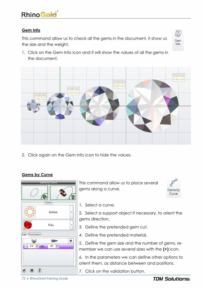
Gem Info
This command allow us to check all the gems in the document, it show us
the size and the weight.
1. Click on the Gem Info icon and it will show the values of all the gems in
the document.
2. Click again on the Gem Info icon to hide the values.
Gems by Curve
This command allow us to place several
gems along a curve.
1. Select a curve.
2. Select a support object if necessary, to orient the
gems direction.
3. Define the pretended gem cut.
4. Define the pretended material.
5. Define the gem size and the number of gems, re-
member we can use several sizes with the (+) icon.
6. In the parameters we can define other options to
orient them, as distance between and positions.
7. Click on the validation button.

73 RhinoGold Training Guide
Gems by 2 Curves
This command allow us to place several
gems between two curves.
1. Select two curves, if necessary we can change
the curves direction in the arrows icon.
2. Define the pretended material.
3. In the parameters we can define the distance
between gems as well as flip their orientation.
4. Click on the preview icon.
5. Click on the validation button.
Exercise:
Open the Gems by 2 curves.3dm file.
1. Execute the Gems by 2 curves command.
2. Select the curves, in this ring are the inside curves.
3. Define the parameters, in this case 0,50mm distance between gems.
4. Click on the preview button.
5. Click on the checkbox to
add the gems to the docu-
ment.

74 RhinoGold Training Guide
Pave Automatic
This tool allow us to create paves automatically as well as place gems dyna-
mically in any object.
1. Start by selecting the object to apply a pave, it
can be a surface, a solid or a mesh.
2. Define the parameters, Gem diameter, distance
between gems, distance to borders and when ne-
cessary activate the option start by borders.
We can also define mirror planes, lock or unlock
gems, change the preview to gems or circles, re-
fresh the gems positions and the (+) icon to add
gems dynamically.
3. In the first tab, we have the info about the gems
on the borders, of the pave, gem size, distance to
borders and number of gems. Very useful when
using the option start by borders.
4. In the second tab we can define different gem
sizes to apply on the pave, max size and min size, as
well as the interval between sizes.
5. In the last tab there are the prongs parameters,
we can actívate this option or not and if yes we can
define the prongs to apply on the pave, the height,
the depth and the overlaping distance to the gems
or the prongs diameter.
6. To apply the pave, after defining all the pretended parameters, we must click on
the preview icon and define a point in the model to start the pave. In any moment
we can use the pause button to stop the pave and, if necessary, adjust the parame-
ters. Is also available the delete icon to remove the placed gems.
7. After defined all the pave positions we must click on the validation button.

75 RhinoGold Training Guide
Exercise:
Open the Pave Automatic.3dm file.
1. Execute the Pave Automatic command.
2. Select the top surface of the ring to apply the
pave.
3. Define the parameters, in this case 2mm gem
size and 0,10mm distance and border gap. In
the second tab from the bottom define the posi-
ble sizes of gems, 2mm until 1,20mm and
0,10mm between sizes.
4. Click on the preview button and then pick the
central point of the surface to start calculating
the gems positions to create the pave.
5. After placed the gems we can use the (+) icon
to add more gems dynamically, if needed.
6. In the last tab from the bottom we can turn ON
the prongs, they will be placed automatically,
then drag a window to select all the prongs in
the Pave and define their measures, in this case
as the next image.
7. Click on the checkbox to add the Pave to the
document.
8. If needed we can edit the prongs, to do it, select
the prongs and press F2, it will open the Prong
Editor tool in the side tab, here we can define all
the parameters, move positions and add more
prongs under the (+) icon.

76 RhinoGold Training Guide
Pave UV
This command allow us to make a pave using the U or V direction of the
surface.
1. Select a surface to apply the pave.
2. Define the material of the gems.
3. Define the gem size.
4. Click on the (+) icon and then pick a point on
the surface to insert the pave. Then we can control
directly on the model the number of gems.
5. After placing the gems we can consult a list of all
the gems applied, size, quantity and weight.
6. Any moment we can remove the gems by cli-
cking on the delete icon.
7. Click on the validation button.
Exercise:
Open the Pave UV.3dm file.
1. Execute the command Pave UV.
2. Select the surface to insert the gems.
3. Define the gems material.
4. Define the gems size.
5. Use the (+) icon to insert the gems dynamically. Place
the gems in rows and use the (+) or (-) icons to add or
remove gems to the row. We can also use the Gumball
to adjust the position and the (X) icon to remove the
row.
6. Click on the checkbox to add the gems to the docu-
ment.

77 RhinoGold Training Guide
Pearls
This command allow us to place round pearls as well as the Pearl wire and
the calotte in a very simple way.
1. Define the Pearl diameter.
2. We have the option to create the wire to support
the Pearl defining his diameter and the lenght.
3. We also have the option to define a calotte in
the bottom part of the Pearl, we can define his pa-
rameters as the angle and the thickness.
4. Under the (+) icon we also have the options to
insert on a surface, on a curve, by points or by
points in a surface.
5. Click on the validation button.
Exercise:
Open the Pearls.3dm file.
1. Execute the Pearls command.
2. Define a Pearl with 9mm diameter.
3. Define the wire with 1mm diameter and 0,50mm lenght.
4. Define the calotte with an
angle of 55 and 0,80mm thi-
ckness.
5. Click on the checkbox to
add the Pearl to the docu-
ment.
6. To finish we can use the
Boolean Union tool in order
to unite all the metal parts in
a single object.

78 RhinoGold Training Guide
Cabochon
This command allow us to create cabochons gem cuts easily.
1. Select the type of cabochon, there are four pre-
defined shapes available.
2. Select the cabochon cut, there are four different
types available.
3. Define all the parameters of the measures in the
cabochon.
4. Under the (+) icon we also have the options to
insert on a surface, on a curve, by points or by
points in a surface.
5. Press the validation button.
Exercise:
Open the Cabochon.3dm file.
1. Execute the Cabochon command.
2. Select oval as type.
3. In the parameter: side, define the second
option.
4. Define the length as 5mm, width 7mm and
height 2,5mm.
5. Click on the checkbox to add the cabo-
chon to the document.

79 RhinoGold Training Guide
Lesson 6 – Jewellery Tools

80 RhinoGold Training Guide
Ring Wizard
This command it's a wizard to create rings. It's easy for new users, and really
useful for expert users.
1. Define the area
2. Define the size
Imagine we are looking at the ring from the front.
We have the option to define until 38 sections. The
idea is, to click on the ring and Define the section,
size, ... We can modify every section independently,
allowing us to define different types of thickness.
Define the area
Define the standard size or create your own ones
Define the profile
There are 38 sections.
Solid / Thickness
Current Profile
Define position, Vertical Rotation, Height and Width

81 RhinoGold Training Guide
3. Define position, rotation, vertical rotation, height and width.
Position: Define the position of the profile.
Rotation: Turn the profile on the curve.
Vertical Rotation: The profile on the curve has to be turned vertically.
Height and Width: Define the sizes of the profile.
Solid: Define the solid profile.
Thickness: Define a thickness of the material.
This image shows the difference
between defining by thickness
profile or solid. You can define
thickness or solid independently
for each profile.
Important
Once the ring is created, it will be shown in the
Browser. Remember, we can edit double clicking
on the Ring Icon.
Creating Profiles
By default, RhinoGold has 20 different profiles, but we can create our own ones.
Exercise:
1. First, draw a curve as in the image. The size is not im-
portant. The profile must be a curve, if you model
more than one, remember to join them. You can use
the AutoConnect command.
2. Open the User Folder Manager in the Profiles tab and click on (+) icon.
3. Select the curve we have previously drawn.
4. Write a name for your profile.
5. You have saved your profile and now, it’s in
the Ring Wizard. Try to do the next ring.

82 RhinoGold Training Guide
Signet Ring
This command creates rings based on the top profile curve
1. Define the area
2. Define the size
3. Define the top profile and measures
4. Define the curve for the side section and the
bottom measure
Important: We can always add more profiles to
create the ring in the top section and the side cur-
ve! Under the user folder select the (+) icon and
choose the pretended curves
5. Define the ring’s front side measures, top, side
and bottom thickness
6. Define the material of the ring
7. Click on the validation button
All the measures can be defined numerically
in the command parameters or dynamically
with the gumballs
Exercise:
Try to do the next ring using the signet ring tool

83 RhinoGold Training Guide
Ring by Curve
This command creates rings based on the frontal curve
1. Define the frontal curve
2. Define the side curve
3. Define the area
4. Define the size
5. Define the top measure
6. Define the Bottom measure
7. Define the side measure
8. Define the side-top measure
9. Define the side-bottom measure
10. Click on the validation button
Important: We can always add more profiles to crea-
te the ring in the frontal section and the side curve!
Under the user folder select the (+) icon and choose
the pretended curves.
All the measures can be defined numerically in the command parameters or dyna-
mically with the gumballs!
Exercise:
Try to do this ring using the ring by curve
tool.

84 RhinoGold Training Guide
Ring by Objects
This command creates a ring from any object.
1. Select the object to create a ring
2. Define the region
3. Define the ring size
4. Option to define the angle with the gumball
5. Option to use the mirror in X or Y axis
Exercise:
1. Open the Ring by Objects.3dm file
2. Use the Ring by Object command and start by selecting the object in plane
3. Define ring size 12 from European measures
4. Open the angle with the Gumball in order to adjust the shape to the head studio
5. If needed use the Reverse option to invert the object direction.
6. Press the checkbox to add the ring to the document.

85 RhinoGold Training Guide
Creating and Managing Profiles
Allows managing our profiles as well as delete or create new ones.
Under the User Forder Manager, in the Profiles tab to do it.
1. Create an open curve
2. Press (+) icon to select the curve to use as profile
3. Give a name to the profile
4. Now the profile is available to be used in the profiles tab
5. To remove a profile, select him and press (-) icon
Important
Remember that profiles are 3dm files who are in the Profiles folder from your User
folder. You may share with other users

86 RhinoGold Training Guide
Gauge: Ring Size Creator
This tool allows us to create a base circle to start creating the ring, using
standard measures from Europe, UK, USA and Japan. We have the possibility
to create our own sizes for those countries with their own standards.
Area and Size:
There are the standard regions, and you can cus-
tomize your own one as well.
Diameter: It allows us to display and modify the cir-
cle, using diameter values or the circumference
length.
Cylinder: Create a cylinder with the size selected.
It's so helpful to delete those zones that interfere in,
as bezels, head...
Angle: It allows us to create open circles
Gem Plane: Allow us to define a plane in the top of
the circle with a specific distance
We also have the possibility to define
all the command parameters directly
with the gumballs.

87 RhinoGold Training Guide
Hollow Ring
This command allow us to hollow rings, defining the pretended thickness.
1. Select the surface(s) to remeve
2. Define the thickness
3. Define with the Gumballs the area to hollow
4. Press validation button
Red area: Area to hollow
Yellow area: Transition area
Remaining area: Solid area
We can use these Gumballs to
control the areas, between the
hollow and the solid part of the
ring.
Exercise:
1. Open the Hollow Ring.3dm file
2. Use the Hollow ring command to hollow the
ring with 1mm thickness

88 RhinoGold Training Guide
Scale Ring
This command allow us to scale rings in multiple sizes with the possibility to
keeping areas.
1. Select the ring to scale
2. Define the region and the pretended ring size
3. Define the angle between the keeping area,
transition area and the area to adapt to the new
size. This is made directly in the ring with gumballs.
4. Press the validation button
Red area: Transition
area
Multiple Sizes:
We also have the possibility to define multiple sizes.
When activated, this option allow us to define the
sizes to get and it will generate the models in diffe-
rent layers or directly to STL file format.
Exercise:
1. Open the Scale Ring.3dm file
2. Adjust the keeping area
3. Define multiple sizes from 10 to 12 ring sizes for example
4. Generate the results in Layers

89 RhinoGold Training Guide
Dynamic Profile
Allows using our section library to move them, rotate them and change the
size. Very helpful to create any type of complement in a matter of seconds.
Profiles are editable by the user.
1. Select a curve to apply the profiles
2. Define the profile to apply
3. Define the profile measures
4. We have the option to add more profiles in any
point of the curve under the (+) icon
5. We have the option to orient the profiles by sur-
face or by any viewport
6. Define the Cap options (none, flat, rounded)
7. Press the validation button
Exercise:
We will see how to create this ring. It is really easy.
Open the Dynamic Profile.3dm file.
1.Execute the Dynamic Profile command.
2.Select the curve to apply the profiles
3.Click on Surface option and choose the cylinder
surface as orientation object.
4. Now we are in the first profile. Please change the
width to 3mm.

90 RhinoGold Training Guide
5. Activate the second profile clicking on (+) and move the profile to the right. And
define a Width.
6. Now we have the same profile at the start and
at the end point on the rail. Activate the 3rd Profi-
le . Change the curve, change the Width to 2mm
and click a point on the rail curve as you can see
on the above picture:
7. Activate the 4th profile clicking on (+). Chan-
ge the curve, change the Width to 2mm and
click a point on the rail curve as you can see on
the picture:.
8. Click on OK button, and you will see in the tree, there is the dynamic profile, and
of course, you can edit it!

91 RhinoGold Training Guide
How create custom regions
Custom region allows us to create your own ring sizes. By default, there are 4
standard sizes (Europe, UK, USA and Japan), but there are countries who use
their own sizes.
Steps to create a region:
1. Click on (+) icon and type the region name.
2. In the table, define the name or number of the size and the diameter.
3. Click on Save icon to finish.
Steps to modify a region:
1. Select the region of the list
2. Modify the values of the table, may adding more values, writting on the last line,
and may delete.
3. Click Save to save the modifications.
Important Note
Each own region is saved in a file with its name. Those files are saved in the User Fol-
der. Remember, you may open the User Folder, clicking on the Open User Folder
icon under the User Folder Manager.

92 RhinoGold Training Guide
Channel Studio
Channel Studio allows us to create channels from the curves.
Exercise:
Open the Channel.3dm file.
1. Execute the Channel command.
2. Select the curve.
3. Select the cylinder. The surface orient the chan-
nel direction. If the stones are inverted, please
click to Flip button.
4. Define the pretended gem cut, brilliant.
5. Define the material.
6. In the parameters we can define the channel
measures and the pretended profile.
7. In the gem and cut tab we can define the size
and number of gems as well the channel cut
where the gems are going to fit.
8. Click in the checkbox to add the channel to the
document.
Important
Remember you can add your own profi-
les to the User Folder Manager to use in
the channel profiles.

93 RhinoGold Training Guide
Cutter Studio
Cutter Studio allows us to create our own parametric and editable cutter.
Exercise:
Open the Cutter Studio.3dm file.
1. Execute the Cutter command.
2. Select the gems. It will show the standard cutter.
3. Define the pretended values in the parameters.
4. In the second tab we can define the inferior part
of the cutters, choose the profile and dimentions.
5. In the third tab we can save our own cutters.
6. Click on the validation button to add the cutters
to the document.
Then we should use the boolean difference tool to
remove the cutters from the ring in order to create
the holes.
Important
Remember you can add your own
profiles to the User Folder Manager
to use in the inferior part of the cut-
ters.

94 RhinoGold Training Guide
Cutters in Line
This command allow us to place horizontal cutters along gems.
1. Select the gems to apply the cutters in line.
2. In the parameters we can choose the pretended
profile for the cutters and define all the measures, if
needed the rotation angle can be adjusted or turn
on the gems orientation.
Important
We can define the values direc-
tly in the model with the gumba-
lls, press Shift key when chan-
ging the values to apply the
changes to all the cutters.
Head Studio
This command allows us to create our own parametric and editable Head.
Exercise:
1. Create a brilliant using Gem Studio.
2. Execute the Bezel Studio command.
3. Select the gem, clicking on the Selection button. It will show a stan-
dard bezel. You can select similar stones (same cut) or all the stones
of the document using the other buttons.

95 RhinoGold Training Guide
4. Then choose a profile, if we are in the prongs tab the profile is applied
in the prongs, if we are in the rails tab the profile is applied to the rails.
5. Choose the material.
6. In the prongs tab we can define all the parame-
ters of the prongs, we also can use the gumballs di-
rectly in the model to define the prongs, in this case
remember that pressing the Shift key the changes
are applied to all the prongs.
7. In the Rails tab we can define all the parameters
to create the rails, number, measures and orientati-
on.
Important
Some parameters are only visible when the profile
chosen is selected.

96 RhinoGold Training Guide
Bezel Studio
This command allows us to create our own parametric and editable bezels.
1. Create a brilliant using Gem Studio.
2. Execute the Bezel Studio command.
3. Select the gem, clicking on the Selection button.
It will show a standard bezel. You can select simi-
lar stones (same cut) or all the stones of the document using the other buttons.
4. Define the Bezel parameters, it can be
done by using the gumballs directly in the
model or setting values in the comand para-
menters.
5. In the second tab we can enable the divisions to
apply in the bezel, all the parameters are editable
with numeric values or with gumballs directly in the
model.

97 RhinoGold Training Guide
Azure
This command allow us to create honeycomb from Paves.
Exercise:
Open the Azure.3dm file.
1. Select the pave.
2. Select the object to apply the azure.
3. Define the values in the parameters.
4. Press the preview icon.
5. Press the validation button to add
the azure to the document.
Prong Studio
This command allow us to define the prongs around a gem.
1. Select a gem.
2. Define the pretended profile.
3. Define the material.
4. Define the values in the parameters.
5. Press the validation button to add the prongs to the
document.

98 RhinoGold Training Guide
Dynamic Prong
This command allow us to place prongs dynamically on a surface.
1. Select the object to apply the prongs.
2. Define the pretended material.
3. Define the values in the parameters.
4. Click on the (+) icon to place the prongs dyna-
mically on the object.
5. We can use mirror if needed.
6. Press the validation button to add the prongs to
the document.
Prongs in Line
This command allow us to place prongs along a line of gems.
1. Select the gems.
2. Define the material.
3. Define the prongs profile.
4. Define the prongs measures.
5. Use the mouse to drag the prongs to the preten-
ded place, it will create a mirror to place the prongs
in the other side of the gem. If we press the Shift key
it will apply the changes to all the prongs.
6. Press the validation button.

99 RhinoGold Training Guide
Chain
This command allow us to create a chain along a curve, from a module.
1. Select the element to duplicate.
2. Select the curve to flow the elements along.
3. Define the number of elements.
4. Include ends option allow us to place two ele-
ments centered in the ends of the curve.
5. Define the rotation of the elements, we have
available two gumballs to rotate dynamically the
elements but we also can define the values numeri-
cally.
6. Press the validation button.
Exercise:
Open the Chain.3dm file.
1. Select the element to multiplicate.
2. Select the circle to create the chain along it.
3. Define the number of elements and activate the option Include Ends.
4. Define the rotation of the elements, in this case 90º in X axis for both.
5. Click on the checkbox to add the chain to the document.

100 RhinoGold Training Guide
Lesson 7 – Artistics Tools

101 RhinoGold Training Guide
Raster to Vector
Convert images and hand drawings to graphic vectors, useful for 3D design,
milling and engraving.
Exercise:
1. Execute the command Raster to Vector in Artistic tab.
2. Select the file Raster to Vector.jpg
3. Define the parameters, in this image there are a
lot of shadows so we can increase the Cleaning
parameter to make less curves.
4. Click on the preview button and verify the results.
5. Click on the check button to add the curves to
the document.
Command Description
Raster to Vector Convert images and hand drawings to graphic vectors, useful for 3D design,
milling and engraving Place Image 1:1 Place drawings or scanned photos at scale 1:1. RhinoEmboss Creates reliefs, engraving, sculpture and texturing. We can create 3D mod-
els from photos and / or curves.
Heightfield Creates a NURBS surface based on grayscale values of the colors in an im-
age file. Heightfield by Colors Creates heightfield identifying the colors of the image. Texture 3D Create 3D textures. These textures are geometrical, allowing us to use for
production. We can manufacture our prototypes with real textures. Texture Creator Allows to define greyscale images from 3D models to create textures. Color by Bitmap Allows to assign colors to objects based on an image.
Celtic Knots This tool allows us to design celtic knots, in 2D and 3D.

102 RhinoGold Training Guide
Place Image 1:1
Place drawings or scanned photos at scale 1:1.
Exercise:
In this exercise we will see how important is use our hand drawings to model our 3D
models easily.
1. Execute the command Place Image 1.1 in Artistics tab, and select the Hand Draw-
ing.jpg file.
The image will be place it on our document, and in the command prompt we can
see the real size in the paper:
The size result is 189.44 in horizontal and 231.78 in vertical
3. Use the drawing commands to redraw the image. You can use curve, line,…

103 RhinoGold Training Guide
Heightfield
Creates a NURBS surface based on grayscale values of the colors in an image file.
Exercise:
In this exercise we will see how create a relief using a grey scale picture. We
can use color pictures and this command will convert to grey scale. If the objective
is a low relief (less than 2-3 mm) we can use directly the picture. If we want an ex-
cellent result in relief higher than 2-3 mm we recommend use an image editor.
1. Execute the command Heightfield and select the Vir-
gin.bmp file.
2. Pick two points to define the corners of the rectan-
gle. Also you can use coordinates, for example: 0,0 for
the first point, and 0,50 for the second point.
3. Define as Number of sample point: 946x1485 (pixels of
the image) and Height 5 milli-
meters. And click on OK button.
This process needs a couple of
minutes depending of the per-
formance of your computer.
You can reduce the points to
200x200
Heightfield by Colors
Creates heightfield indentifying the colors of the image.
Exercise:
In this exercise we will see how create a relief using a
color image. It is really useful because we can define a
height for each color.
1. Execute the command Heightfield by Color.
2. Select the file Barça.png
3. You will see the list of the color available in this image,
please define as the image:

104 RhinoGold Training Guide
4. In the parameters define Width 50 and Height 50.
5. Click on Preview button to see the 3D.
If you want to change any value, click on Preview
button to update.
6. Click OK button to add the 3D to the document.
Use the Splop (Deformation Tools) and Ring Wizard to
create the follow model.
Texture 3D
Create 3D textures. These textures are geometrical, allowing us to use for
production. We can manufacture our prototypes with real textures.
Exercise:
In this exercise we will see how create a texture on a ring. Open
the Texture 3d.3dm file.
1. Execute the command Texture 3D.
2. Click on Select button and select the surface on create the
relief.
3. Define the parameters as you can see in the picture:
4. Click on the checkbox (Fix Edges)
to fix the edges to the original sur-
face, and click on Preview button.
RhinoGold will start to create the tex-
ture. This computation is complex.
Don’t worry if the computer spend some seconds or
minutes. If you like it, click on OK button.

105 RhinoGold Training Guide
Texture Creator
This tool allow to define greyscale images from 3D objects to create textures.
1. Select the Objects.
2. Define the pattern measures.
3. Click on the preview button to see the result.
4. Click on the checkbox to to create the texture.
5. Name the texture to save it in the user folder.
Celtic Knot Studio
This tool allows us to design Celtic knots, in 2D and 3D.
Exercise:
1. Execute the command Celtic Knot and draw the next pattern:
2. Select Style Solid Square, click OK button and select a point on the CPlane. Just a
point, you can save and load your patterns. In the RhinoGold exercises folder there
is a sample file to load it: Celtic Knot Sample.

106 RhinoGold Training Guide
Lesson 8 – Manufacturing

107 RhinoGold Training Guide
STL Wizard
Wizard to repair and export geometry to STL for 3D Printers.
Exercise:
Open the STL Wizard.3dm file
1. Execute the command STL Wizard.
2. With the Select objects button, select the model:
3. Define the Mesh resolution High.
We recommend you to use Medium or High resolution.

108 RhinoGold Training Guide
4. Click on the checkbox and automatically will shows a Save as dialog to type the
file name:
Check the selected Meshes and try to automaticaly repair meshes
Creates polygon meshes from NURBS surfaces or polysurfaces.
Convert each polygon in a polygon mesh into a NURBS surface.
Creates a polygon mesh from point objects.
Creates a mesh from curves and points.
Creates a mesh based on hue, saturation, value and RGB
numbers of the colors in an image file. The mesh object re-
tains the colors in the image file.
Repair STL Manually
In some cases, when our model is wrong, we have the option to modify and fix the
mesh problems manually. These set of tools are really powerful. We will talk deeper in
the level II.

109 RhinoGold Training Guide
Command Description
Add Triangle Fills a mesh hole with a single mesh face, which helps clean up, repair,
and close mesh
Extract Mesh
Faces Extract faces of a mesh
Connected Faces Separates from the parent mesh those faces connected to a selected
face where the angle between the connected faces is within defined
limits. Duplicate Faces Separates identical faces in a single mesh from the parent mesh.
By Edge Length Separates faces from the parent mesh that have an edge length great-
er or less than a specified value.
By Aspect Ratio Separates faces from the parent mesh that are greater than the speci-
fied aspect ratio limit.
By Area Separates faces from the parent mesh that are within a specified range
of area.
By Draft Angle Separates faces from the parent mesh based on the angle of the faces
to the view.
Extract Part Separates faces from the parent mesh based on the angle of the faces
to the view.
Extract Edges Separates faces from the parent mesh based on the angle of the faces
to the view.

110 RhinoGold Training Guide
Command Description Collapse Mesh
Edge Length Moves the vertices of mesh edges that are greater or less than a speci-
fied length to a single vertex
Aspect Ratio Moves the vertices of mesh faces that are greater than a specified ratio
of length to width to a single vertex
Face Area Moves the vertices of mesh faces that are greater than a specified ratio
of length to width to a single vertex
Collapse Face Moves the vertices of a mesh face to a single vertex,
Collapse Edge Moves the vertices of a mesh edge to a single vertex
Collapse Vertex Moves a selected mesh vertex to the location of an adjacent mesh ver-
tex
Align Vertex Forces mesh vertices within a specified distance to the same location. Delete Face Removes selected mesh faces from the parent mesh creating a hole
Fill Hole Fills a hole in the mesh selected by picking the hole edge.
Fill Holes Fills all holes in a polygon mesh object with triangular faces
Rebuild Strips texture coordinate, vertex colors, surface curvatures and surface
parameters from a mesh and recreates only the face and vertex nor-
mals
Rebuild Normals Removes mesh normals and reconstructs the face and vertex normals
based on the orientation of the faces
Weld Removes creases by merging coincident mesh vertices.
Unweld Adds texture mapping coordinate information to each shared mesh
vertex
Weld Vertices Removes texture mapping coordinate information from each selected
mesh vertex.
Weld Edge Removes texture mapping coordinate information from each selected
mesh vertex.
Unweld Edge Adds texture mapping coordinate information to each shared mesh
vertex
Split Mesh Edge Divides a mesh edge to create two or more triangles
Swap Mesh Transposes the corners of mesh triangles that share an edge

111 RhinoGold Training Guide
Command Description
Boolean Union Cuts away the shared areas of selected meshes, polysurfaces , or surfac-
es and creates a single mesh from the unshared areas.
Boolean Difference Cuts away the shared areas of selected meshes, polysurfaces , or surfac-
es with another set of meshes, polysurfaces, or surfaces.
Boolean Intersec-
tion Cuts away the unshared areas of selected meshes, polysurfaces , or sur-
faces.
Boolean Split Cuts away shared areas of selected meshes, polysurfaces , or surfaces
and creates separate meshes from the shared and unshared parts.
Intersection Creates a polyline at the intersection of mesh objects.
Split Mesh Divides meshes into parts with another object.
Trim Mesh Deletes selected portions of a mesh inside or outside where they are in-
Split Disjoint Divides into separate mesh objects meshes that do not connect, but are
Extract Boundary Creates a polyline that duplicates the boundary of a mesh hole.
Offset Mesh Copies a mesh so that all vertices on the copied mesh are a specified
Naked Edges Highlights edges of surfaces and polysurfaces.
Naked EdgesOff Hide the highlights edges of Naked Edges command.
Split Merge Copies a mesh so that all vertices on the copied mesh are a specified
Merge Edge Combines adjacent edges of the same simple surface into one edge.
Join 2 Naked Ed-
ges Join two naked edges that are out of tolerance.
Rebuild Edges Restores original 3-D surface edges that have been forced away from
Select Open
Polysurface Select the open polysurfaces

112 RhinoGold Training Guide
Exercise:
Open the Repair STL Manually.3dm file
1. Execute the command Naked Edges and in the dialog, click on Naked
Edges options. Take a look to the model, you will see this model has three
problems.
2. As you can see, there is a problem in this edge. We will use the command
Delete Face to remove the bad faces:

113 RhinoGold Training Guide
3. Take a look all the model, and you will see there are two holes on the mesh. It is
not good for 3D printers.
Execute the command Fill Holes (sub-menu Fill Hole) to fix the holes.
4. The model is near to be ready. Before to export to STL, change
the view mode to Rendered.
There is a problem of Normal. Execute the command Rebuild Normals.
Now your model is ready to prototype.
Click on the menu File > Save As > Export to STL

114 RhinoGold Training Guide
Support
Allows to create supports easily. Indispensable tool for resin 3d printer users as
DWS, Envisiontech,...
Exercise:
Open the support.3dm file.
1. Execute the Support tool and sellect the ring.
2. Define the display mode, we recommend the
Green sphere and it will show us the places that
need supports
in red color.
Note: The support
command only
works with mesh
objects.
3. Then we can define the distance to base, in this case 3mm.
4. Other parameter is the base thickness, it can be defined with the following
icon.
5. Now we just need to apply the supports with
the several tools available to do it. In this case we
just need to define the measures of the supports
and place them dynami-
cally in the model.
All the supports are oriented by Gumballs so we can adjust
all the parameters.
6. Click on the checkbox to add to the document the mo-
del with the supports united as one single object. It will main-
tain the original ring without supports.

115 RhinoGold Training Guide
Milling Support Structures
Allows creating and/or inserting milling structures. These structures are
really important to support our model while the CNC machine mills it.
Note: To add our own structures we just need to click on the (+) icon and select the
3DM file to insert, then it will be available in the user folder under the MSS tab.
Organize
Allows to select a 3D Printer, place and or-
ganize the models to be printed.
1. Select the 3D Printer to use, it will display the se-
lected parameters as, base, work area and objects
collision.
2. Define the model to add and the number of
copies, as well as the distance between them.
3. Click on the checkbox to add the models to the
document.

116 RhinoGold Training Guide
Under the menu File > Options we can manage and add 3D Printers, as well as, defi-
ne the STL parameters.
Define 3D Printer
Under the (+) icon we can define a new
3D Printer, just need to insert the para-
meters of the machine and then click
on the checkbox to add it.

117 RhinoGold Training Guide
Lesson 9 – Engraving

118 RhinoGold Training Guide
Line type
Displays curves using their Linetype properties.
Set LineType - Specifies a linetype for the selected curves.
1. Select curves.
2. In the Select Linetypes dialog box, select a linety-
pe from the list.
Hatch
Creates a pattern of lines to fill a selected bounding curves.
1. Select closed planar curves.
2. Specify the pattern, scale, and rotation.
Command-Line Options;
Boundary: Click inside a closed boundary to hatch that area.
CombineRegions: Yes - Selected regions combine to create a single hatch.
No - Each region is hatched separately.
Note: The input curves can be in model space or layout space or a combination of
these. Control points can turned on for hatches so that the shape of the hatch can
be adjusted.
Color
Select the curves or objects and define the pretended color.

119 RhinoGold Training Guide
Nesting
Allows the optimization and orientation of objects to save material.
Optimise the position and orientation for cutting and engraving material.
1. Define the area to Nest.
2. Define the number of copies.
3. Add objects to copy.
4. Define the distance between objects.
5. Click on the checkbox to aprove the results.
Export to SVG or HPGL
The most popular file formats for cutting and engraving machines are now available.
Text
Intuitive tolos to insert, edit and find text in our documents!

120 RhinoGold Training Guide
Lesson 10 – Animation and
Render

121 RhinoGold Training Guide
It's really worth to communicate our designs to our work team or customers. For this
reason, RhinoGold is compatible with all the renders available for Rhinoceros, as Fla-
mingo, Brazil, Hypershot, VRay, etc.
Other interesting tool is the new Animation Studio. This functionality allows to
create videos easily.
Exercise:
Open the Animation Studio.3dm file.
1. Select the circle for the camera travelling.
2. In settings, define the video duration. In this case,
we define 10 seconds.
3. Then define the Email, Web or DVD quality. It de-
fines FPS (Frames per second). Define Web quality.
4. Finally define the resolution, we can use 1280X720.
5. To preview the animation press Play
6. To create the animation click on the checkbox,
we can activate the option: Use Render and it will
create a render for each frame.
How to select the preferred Rendering?
On the Render Tab, click on the black triangle to show the rendering list. Obviously,
you have to install the chosen render. For all of them, you can render clicking on
Render Icon.
How to use a render out from the list?
Click on Select Render icon, and write the rendering
plug-in name.

122 RhinoGold Training Guide
RhinoGold Render Studio
Render Studio allow us to create photorealistic images from 3D models.
After execute the Render Studio tool more op-
tions will be available in the side tab.
1. Define the environment.
2. Define the ground.
3. Choose the materials to apply in the mod-
el, this ones are different from the Real time
rendering Materials.
4. Define the render resolution.
5. Option to create Web 3D, it’s interactive
images to publish online.
Scenarios
We can use
the scenarios
in rendering,
just select the
pretended
one and it will
be added to
the document.
Under the (+)
icon we can
define more
scenarios to
add in the User
Folder Manag-
er.

123 RhinoGold Training Guide
Lesson 11 – Analyse

124 RhinoGold Training Guide
Command Description
Coord Reports the world and construction plane coordinates of a selected
Length Measures and reports the length of curves or edges.
Distance Measures the distance between two points.
Angle Measures and reports the radius of a curve at a specified point.
Radius Measures and reports the angle between two lines.
Area Calculates the surface area of closed planar curves, surfaces, pol-
Volume Calculates and reports the volume of a closed surfaces, polysurfaces,
Centroid Calculates and reports the volume centroid.
Metal Weight Calculate the metal weight
Weight by area This tool allow us to know the weight if added a plated metal to his sur-
face.
Direction Displays an object's normal direction and allows you to change it.
Continuity Analyzes and reports the geometric continuity between two curves.
Bounce Shoots a ray at a collection of surfaces and creates a polyline path.
Curve Deviation Measures and reports the maximum and minimum distances between
Select Bad Objects Select all objects that do not pass Check.

125 RhinoGold Training Guide
Exercise:
In this exercise, we analyze the dimensions of the objects.
Open the Analyse.3dm file.
1. Select the Analyse Tab and analyze dimensions of this objects.
2. Using the 3D ring, analyze the volume, the area, the metal weight in Gold 24k and
Silver.
Exercise:
In this exercise, we analyze the weight of the metal. Open the Weight.3dm file.
1. Execute the command Metal Weight.
2. Select objects to analyze. In this case, select the ring metal.
3. It will display a box around the ring with the
weight and the material.
Note: To change the material we can choose
any other material from the RhinoGold - Materi-
als library.

126 RhinoGold Training Guide
Report
Creates a report of all the gems and metals from de document.
It’s available under the menu File. When running the command, the model will be
analyzed and the following dialog box will be shown:
The report shows by gem's type and dimensions. As well as Weight for Gem, Weight
for Metals and time management.
The option to save it available, allowing printing, modifying...

127 RhinoGold Training Guide
Weight By Area
Allows to know the weight if added a plated metal to the objects surface.
1. Select the object to analyze.
2. Define the thickness of the plating.
3. Choose the plating metal.
4. See the weight.
RhinoGold - Material Selector
We also have available the Material Selector in
the side tab, there are the materials applied in
the document and we can select the objects by
their material.