rheological & physical | property analysers · rheological & physical | property analysers...
TRANSCRIPT

Rheological & Physical | Property AnalysersR & D, QC, Lab & on-line application
The solution for the polymer & petrochemical industries
The original by OCS

The function of the OP5 is to make certified
measurements of the melt index and/or polydis-
persity of small solid polymer samples. The primary
duty of these measurements is overall control
of many types of polymerisation processes. This
ensures that the product can be made to specific
formulations. The secondary duty is quality control
in final product selling specification and in batch
control. The OP5 is logically situated in the plant
analysis laboratory, which ensures best reliability
and maintainability for these calibrated, precision
measurements. Representative samples are
therefore transported from various locations
of the polymer manufacturing plant at the call
of each analyser. Process control and QC are
full-time activities, which require, as a minimum,
one sampling point for each analyser.
Representative samples are extracted from each
reactor stage and from the finished product. In
simple plant configurations, such as LDPE, PS,
PET and nylon this usually means one OP5 but in
complex plants such as PP, HDPE and LLDPE two
or more OP5 analysers would be required. The
complex plants have powder samplers, which have
degassing and catalyst deactivation stages close
the analyser. At the plant end, these samplers can
extract at the main discharge valve(s) of the reactor
or at the primary degassing vessel, etc. according
to the plant configuration. In the case of the pellet
samples, these would normally be supplied from
central (OCS) source, and in such cases the supply
to the rheometers carries a priority to minimise
the sampling delay time.
Melt flow measurements are performed after
the solid sample is melted and conditioned to the
appropriate test temperature. In the OP5 the
melting process minimises any changes to the
structure of the polymer but making a very rapid
transition from solid to liquid, which substantially
obviates shear damage, cross-linking, thermal
On-line RheometerOP5
Plant optimisation &improved product quality

degradation and other degradation processes.
This sample preparation removes the last traces
of any trapped air or gas and overall makes an
important contribution to rendering the sample
at the point of measurement fully representative
of the process. In this unique way the OP5 makes
control through rheology as reality.
The melt flow is regulated by a sealed gear pump,
which transports a metered quantity through a
shaped die which has the normal MI die L/D. The
shaping of the die is to minimise the delay in the
slow moving polymer near the walls, without deviating
the actual rheology relationships too far from the
standard MI die.
Measurements of pressure and flow rate are
used to derive the standard melt index. Many
features of the apparatus for measurements are
covered in the patents.
The patent, melt flow determination in polymer
process, has the following grants, EU 989 45440,
GB 233 4958 and US 09/622558. These
patents also have integrated process control
application. Systematic correlations are applied
to compensate for the relationship between the
OP5 die and the lab test die (both ASTM D1238
and ISO 1133 tests use the same die form). The
corrections derived from these correlations are
specific to the actual polymer process and the local
Wastage(with OP5)
Wastage(without OP5)
test methodology used to make the test. This is
because each plant produces subtly different
polymer structures and the manual test method
result varies with operator and procedures. Once
established the corrections do require regular
verification, which is supplied through the OP5
operating software. The IPR of the operations are
described in the EU CTM, Registration Certificate
No 002729309. The methodology of calibration
and measurement gives the OP5 class leading
accuracy, which can be used to certify the finished
product and thus completely replace routine testing
using the lab melt indexers.
The OP5 measurement of melt index is performed
in a batch process, termed a cycle. The MI result
is based on a tiny part of the sample, which gives
the OP5 a pin point accuracy. The result shows
every small variation in the polymer product and
which can be used to steer polymer reactions in
a way not possible by long term averaging or less
than adequate sample preparation.
The MI result can of course be used for quality
control but the finely resolved and accurate
measurements will bring a better precision and
thus maximise the added value of the production.

Typically the OP5 samples every 5 minutes to fit
in with the cleaning-measurement-sequence. The
delay of measurement is slightly greater than cycle
time of the sequence. Although the cycle has been
optimised for accuracy but by using the necessary
cleaning part of the cycle, the delay is made nearly
independent of sample MI value. The real time
delay (7–10 min) between the reaction and the
measurement, which includes any sampling and
sample preparation delay, is comfortably below
process requirements whether it is used for
reaction control and QC. In fact provided the delay
is adequate, process control and QC places a very
strong requirements on full-time calibration and
best accuracy.
The unique features of the OP5 equipment open
up the huge opportunity of process control
through rheology.
I. Key statementPositive control of the polymerisation process
from MFI provides the definitive means of making to
recipe. An integrated approach results in improved
plant efficiency and product quality. With a full
understanding of the processes involved, lasting
benefits to the whole of the polymer industry, from
manufacturer to down stream processor will
surely follow.
II. IntroductionThe continuing need for optimisation of polymer
plants, as with any process, is self evident. A fresh
approach has been needed, since the subject has
received close attention from major plant suppliers
and polymer manufacturers.
Key polymer properties, such as tensile strength,
impact resistance and melt viscosity, are related
to Average Molecular Weight (AMW).
Polymer production relies on close control of
melt viscosity, which in turn determines the main
properties of the material. The viscosity measure-
ment is reported as melt flow index (MFI).
MFI is used world wide as the classification of
product properties. This measurement is therefore
equally relevant to the finished product and the
conversion process, such as moulding or extrusion.
Ziegler-Natta catalytic reactions produce ultimately
in fine powder form by continuous polymerisation,
initially in a gas phase, or in a slurry phase, or
both.
In these systems, primary control of the molecular
weight is achieved by inhibition of chain growth
using a terminator agent known as a Chain Transfer
Agent (CTA). The relationship between CTA and
Control & optimisation of polymerisation by usingmelt index

MFI in steady state takes the general form:
Log (MFI) = A + B x log (CTA/monomer)
Our control scheme for this type of polymerisation
requires powder and gas sampling from, or close
to, the reactor(s), in order to measure MFI and
CTA at the reactor. The sampling, preparation and
measurement has to be done without long delay
times or changes in properties.
Together these two measurements form a
cascaded control set up that has allowed fine
adjustment of the polymer properties at source.
Many aspects of this control and measurement
scheme have been patented following successful
closed loop operation of a leading gas phase PP
process.
This approach can be equally applied to many
other reactions including some LDPE processes.
In all cases the opportunity arises for a more
powerful optimisation of the process when this
feedback technique is used in conjunction with any
APC. The programme is also supportive to many
existing plant developments.
Any future implementation of such a control
scheme requires close cooperation between the
polymer company management and the technology
supplier. OCS is willing and capable of undertaking
their side of any contractual intent.
III. Difficulties of process control
ConservatismRheology is not seen as an important part of the
control solution in the polymer industry. MFI is
used mainly as the QA tool for the final product
selection.
ProcessMany conventional processes have advanced by
adopting modelling approaches (SPC) and by paying
meticulous attention to many process meas-
urements, and their subsidiary control loops.
The example of control of LDPE, demonstrates
that APC works with measurable success on this
‘simple’ type of process. It has only become possib-
le for the clear reason that the delay, frequency
and accuracy of standard non-automated MFI meas-
urements can just about cope with the driveoff
rates. Short term MFI is calculated from other
plant variables.
In many Ziegler-Natta processes it can be very
difficult to maintain steady conditions in the reactor
even with modern gas chromatography equip-
ment used for the control of CTA concentration.
EX-REACTOR SAMPLES
CLO
SED
LO
OP
CO
NTR
OL
ADDITIVES
GRADEMODIFIER
DEACTIVATION
DCS REACTORCONTROL
OP5RHEOMETER(POWDER)
OP5RHEOMETER
(PELLETS)
STD DEVIATION
SPECIFICATIONLIMITS
CP
CPLle
CALIBRATIONSAMPLE
POWDER MFI
QC MFI
QUALITY CONTROL
OCS POLYMER PLANT CONTROL
FINISHED PRODUCT SAMPLES
REA
CTO
R

Unsteady reactor conditions result in the manu-
facture of a wide variety of product structures,
some of which will require down grading. Less
frequent grade changes can reduce this but at a
cost of higher stock levels. Up to 15% of product
can be downgraded. Even good product so produced
can have a large scatter of MFI. Downstream this
can result in a 4% chance of receiving two successive
batches at opposite ends of the allowable range.
No help is available from calculations or MFI
measurement too late in the process. In-reactor
or ex-reactor MFI is mandatory.
System errors and delaysOften these two types of error together will totally
hide the essential control relationships.
ErrorsIt is accepted that the MFI manual method can
have standard deviations that are as high as 10%
at extremes of range. Even the most modern lab
equipment is barely acceptable as a control tool.
There is little help from the automatic MFI equip-
ment because the relationship between their values
and MFI are neither simple nor consistent.
Polymer, powder especially, can easily be changed
prior to measurement. Small extruder screw heating
causes shear damage, mixing and thermal degra-
dation – thus introducing large representation
errors of the source polymer, making control
impossible.
High mileage catalysts are very susceptible to min-
ute traces of gas impurities. Gas impurities can
lead to unknown errors in CTA-MFI relationship.
These systems are vulnerable to changing the
cracker (gas supply source) and reinforce the
need for reduced errors to cope with a better
recovery of control.
Much of the variability can be due to unpredictable
changes to the polymer, which can occur immediately
after the sampling. Ex-reactor sample requires
early preconditioning to remove monomer and
the activity of the catalyst. Even when the catalyst
is killed the residues will cause chain breakage,
especially if oxygen, shear and heat are applied.

DelaysSampling and measurement both incur delay:
variable delay will result in degradation of control
performance.
A measurement delay behind the reactor of greater
than 20 minutes will typically ruin any feedback
control, if the reaction that has a response time
of 90 minutes.
Placements of MFI facilitiesThe new control duties qualify the complete system
for the plant-critical list, in a similar fashion as the
CTA measurement and control facility.
Accordingly the powder MFI analysers must be
placed in a suitable area where they can be
properly serviced and calibrated. The plant samplers
must meet ATEX requirements, as they will be
placed in a hazardous area.
Cycloneseperator
Sampler withoverflow
MFI setpoint
MFI controller
MFI output
CTA set point CTA flowcomparator
CTA concentrationcontroller
CTA flowmeter/sensor
CTA adjustmentvalve
CTA supply
Sensing gaschromatograph
OP5 MFIanalyser
Polymerisationreactor
Reactor output
Sampler
Schematic for MFI/CTA controlled polymerisation reaction
Reaction control from pelletsThe control of reaction from the finished product
needs to be completely rethought. The main extruder
placement fails to provide a site for accurate
automatic MFI determination. This is mainly
due to calibration drift at grade changes, which
renders the equipment unusable during critical
times. In most cases, particularly in visbreaking PP
applications, the extruder sample does not represent
the finished product. Maintainability at the main
extruder site is below the standard required.
Successful as it is, the APC approach does not
provide any regular quality assurance of finished
product during normal running. During process
excursions or grade changes QA completely
breaks down, causing more than necessary product
to be segregated and handled separately. Out of
necessity current APC still prefers to calculate
MFI or AMW.

IV. The four part OCS solution
a) Incorporation of rheology intoprocess controlTo stabilise the process
b) Sampling from the reactor andfinished productsTo represent process at key points
To measure in suitable environment
c) Better rheology measurement,suitable for process & QC alikeTo measure the process faithfully
To achieve full-time calibration
To achieve rapid response
d) Integration of measurements into APCTo gain advantage of ongoing optimisation
a) Rheology in process controlWhere the delay from the reactor to finished
product is small, the measurement of pellet MFI
has been shown to be entirely suitable as the
means to control the reaction. LDPE falls into this
category but so does any extruder-based reaction,
such as the visbreaking of PP by peroxide.
Complex plants, typified by the PP process, have
one or more monomer reaction stages. Long time
delays between these reactors and the finished
product require us to use the ex-reactor product
for the means of feedback control. This type of
control has been achieved using the MFI-CTA
relationship, which is briefly described below.
The CTA-MFI control diagram shows the schematic
for the monomer reaction equation.
Log (MFI) = A + B x log ({CTA}/{monomer})
Where
{CTA} = molar concentration of CTA
{monomer} = molar concentration of monomer
A similar equation applies where only the CTA flow
can be measured but with new A/B values.
The reaction controller works as a pair of cascaded
loops. The inner loop controls the CTA flow to
obtain a given concentration/flow. The outer loop
controls the set point for the flow controller from
the OP5 output and the MFI set point of the
recipe.
The inhibitor leaves the catalyst able to start
polymerisation of a new chain.
Natural termination of very long chains, which is
known as Thermal Termination, occurs at low CTA
concentrations.
Similar equations apply in the other major reactions
including all types of PE and PS.
Visbreaking in PP works in a similar way and uses
peroxide as the chain breaker.
Extensive regression analysis, taking care to cover
steady state and transition conditions, is a pre-

cursor for feedback control and of course APC.
We advance with the new MFI factor, by making
the control much more definitive and therefore
more stable. But more importantly the opportunity
to gather very accurate information on an on-
going basis will allow the process to be optimised.
At this better level of stability the APC model can
now ‘afford’ to become adaptive. Process people
will recognise that this will provide a strong plat-
form for product development.
We find that MFI is a key process driver and when
correctly integrated into the control system it
provides a safe and secure way of operation.
b) Representative sampling at key points
MFI equipment that can equally handle powder
and pellets without change, opens up the practicality
of the centralised measurement facility. Remote
sampling and sample transport are key. The ad-
vantages that accrue from this approach (main-
tainability, system back up, reliability, low delay,
accuracy) are fully in keeping with the extra duties
of control.
Finished product samplingHas shown itself to be the best representative of
the low delay categories of reaction. (LDPE, PS
and PP visbreaking etc.) OCS routinely supplies
industry quality samplers and sample distribution
systems. These extract sample directly after the
extruder and transport the product to the analyser
house or laboratory with a minimal delay.
There is every reason to use the OP5 as a combined
QC and reaction control tool in these instances.
Ex-reactor samplingThe control of the reactor has been shown to be
possible by sampling directly at the main discharge
valves, which are situated within a metre of the
reactor outlets. These standard, heavy duty valves
have been modified to become four port valves. A
small quantity of polymer and gas becomes trapped
each time the valve is closed.
At the request from the MFI powder analyser,
through the DCS, the slave PLC sequences a timed
blow of high pressure nitrogen to eject the sample
through the auxiliary ports. The nitrogen charge
acts as a diluent to the monomer. The PLC ensures
that by the time the sample has been transported
to the cyclone above the OP5, the monomer
concentration will be below 10% of LEL. Safety
checking to full ATEX certification is accomplished
via pressure level interlocks to make a robust fail-
safe system. This sampler contributes only 60s to
the measurement delay.
Other systems have been used for powder
measurement. Sample is extracted after the primary
degassing stages. Again transport is by nitrogen.
These systems provide essential information of
reactor product condition but at a considerably
longer delay (10 - 30 min, according to plant design).
This information can establish the control para-
meters but is more suitable for model (APC) pur-
poses than direct feedback control. However our
ultimate intention is to provide an optimisation
facility through APC.
Any sample from the reactor will contain live
catalyst. The entire sampler and front end of the
OP5 analyser is therefore designed as a closed
system to prevent or limit further reaction. The
transport gasses are vented to flare or back to
the process. Catalyst residues are handled inside
the analyser.
Transport of sample (powder or pellets) over long
distances is not an obstacle. Sample can be safely
moved over large distances (> 330m) without
loss of representation or either reactor or finished
product information. Delay is not significant.
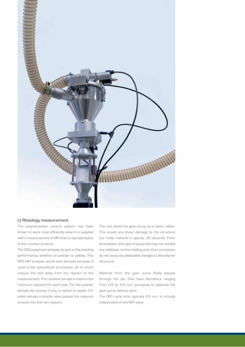
c) Rheology measurementThe polymerisation control system has been
shown to work most efficiently when it is supplied
with a measurement of MFI that is representative
of the reaction product.
The OCS equipment achieves its part in this exacting
performance, whether on powder or pellets. This
OP5 MFI analyser works with discrete samples. It
uses a few specialised processes, all of which
reduce the real delay from the reactor to the
measurement. The received sample is sized to the
minimum required for each test. For the powder
sample the excess, if any, is valved to waste. For
pellet sample a shuttle valve passes the required
amount into the ram system.
The ram feeds the gear pump via a static melter.
This avoids any shear damage to the structure
but melts material in approx. 30 seconds. From
its inception, this type of equipment has not needed
any additives, as the melting and other processes
do not cause any detectable changes to the polymer
structure.
Material from the gear pump finally passes
through the die. Dies have diameters ranging
from 0.6 to 4.5 mm, principally to optimise the
gear pump delivery span.
The OP5 cycle time, typically 4,5 min, is virtually
independent of the MFI value.

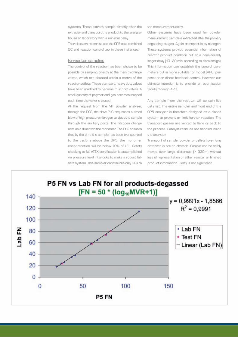
The cycle starts with a purge, to clean out the old
material. This is followed by a measurement that
has two flow rates, which straddle the appropriate
lab MFI pressure condition. The two flow rates
and pressures allow close emulation of the standard
MFI test. This complete technique also has the
merits of very tight calibration to the standard lab
without the drawback of variable delay according
to grade value. The graph above shows a typical
calibration with the Lab standard. One die normally
suffices for the entire product range.
The present design of the OP5 is a culmination of
many years of application in the control and QC
fields, which has fully realised the twofold vision of
CTA-MFI polymerisation control and the certification
of finished product.
d) The integrated control schemeIt is intended that the process be controlled at the
reactor(s), using means as described. Although
the approach has been proven on PP gas phase
and LDPE process it is still a relatively unknown
area to most users.
To facilitate a more complete understanding of
the processes involved and it’s implications, one
examples is laid out in some detail below. Similar
templates can be prepared for other processes.

The programme for PP – all variants including
co-polymer:
Objectives1. To measure ex-reactor powder in real time
2. To control visbreaking from MFI
3. To improve transition times
4. To minimise in-spec variations
5. To narrow blend max/min values closer to
target
6. To provide platform for product enhance-
ments and development
Requirements1. Finished product testing equipment : 1 per reactor
OP5 equipped for powder use, 1 per reactor
PTS from powder source, 1 x OP5, 1 x PTS from
pelletiser, 1 x central distribution centre priority
to OP5, plus PS200C/FSA100/APLAIRS®
equipment according to choice.
The powder sampling and analyser requirement
is onerous. But the information supplies important
reaction data that is crucial to fine control and
model making under a wide range of conditions,
including varying impurity levels should these
occur in the gas supply chain.
2. Plant assumed to be already equipped with
adequate level of instrumentation and DCS
with access for OPC preferred connection to
OCS equipment.
3. LAN processing facilities to be considered for
additional data handling.
4. APC package – to be capable of incorporation
of additional inputs from MFI – to be capable of
model update by continuing regression analysis.
5. Plant assumed to be fitted with sufficient tem-
porary storage vessels etc. for cut and re-feed
of transition and process excursion product.
6. Plant assumed to be adequately covered by
24/7 maintenance and support. Global support
for OP5 and other, available via OCS.
Programme: Ongoing optimisation programme
Task 1: Management and technical support
It is part of the contract that OCS is fully represented
and responsible on an ongoing basis in these two
functions.
Task 2 : Visbreaking control
Using pellet OP5 only. It is not necessary to have
information of the powder MVR to make a premium
control.
Task 3 : Full-time calibration
Using 1/day lab x-check and routine system
maintenance of OP5.
Task 4: Replacement of MFI/AMW calculations in
APC with real time OP5 measurement.
Task progress can be made only if rheometer has
highest data quality and sufficient frequency i.e.
OP5.
Task 5: Routine maintenance of APC modelling
analysis incorporating OP5 output.
With particular note to irregular impurity/gas
conditions and grade changes. Need for pinpoint
timing and accuracy to characterise grade
change materials, possible need for sample capacity
storage to examine grade changes.
Plant/cracker may require modifications to clean-up
gas impurities.
V. Deliverables
Visbreaking controller
Reaction control with improved stability and
resistance to gas conditions
Improved plant utilisation
Improved plant performance
Reduced storage requirement
Improved product quality
Improved customer satisfaction
Better defined product specification leading to
product development from large scale production
Plant optimisation, subject to agreed programme

Performance Characteristics
• Controls
Menu-driven Windows interface and easy
customisation
• Optimum location
Use of laboratory environment to ensure
high run time and accessibility for calibration
and any maintenance
• Low delay time
Fast sampling, sample preparation and
measurement results in delay time more
than adequate for control
• Accuracy
Calibration is established by Transfer
Standard™
• Optional full-time statistical
process control packages
• Full-time calibration
A statistical calibration system that conforms
OP5 to the ISO 1133 or ASTM D1238
standards full-time
• Tables
Tabular display according to individual cycle
measurements of temperatures, pressure,
flow rate, consumed weight of material, test
results
• Set points
Tabular display of all set points
• Real time display
Continuous trend display of MI with tramlines
Additional trend displays, temperatures,
pressures, mass flow, total mass flow
• Recipe control of cycle and conditions
Operator control via menu of parameters,
sequences and user product names
• Alarms
External alarm interface
• Open database
All records can be converted into any standard
file format
• Access
Password protected to 2 levels

Scope of Application
Powder or pellets from polymer processes
Powder ex-reaction
Pellets post extrusion
Samples transported to laboratory via OCS
systems
Technical Data
• Melt flow range
0.05 - 1000
• Shear rate range
0.1 - 2.5 x 10⁵ sec-1
• Test temperature
Up to 320 °C (400 - 450 °C on request)
• Repeatability
Base 3 - Sigma level of +/- 1%
• Pellet/Powder consumption
Approx. 0.6 kg/h
• Sampler feed arrangements
Called on demand from OCS sampler
• Device interface
Ethernet 10/100 M Base T
• Remote control
WEB interface
• Size dimension
(l, w, h) 120 x 60 x 205 cm
Weight approx. 350 kg
• Power supply
400 V, 3 phase + N + PE (5 wires)
• Compressed air supply
Inlet pressure: 6 - 10 bar
Volume flow rate: 300 Nl/min
• Temperature
10 - 40 °C
Optional
• Computer
Industrial Intel®Core™ 2 Duo
Up-to-date-technology
• Software
Operating system Windows XP Professional
(latest technology)
• Physical interfaces
[DC per external server]
Ethernet 10/100/1000 M Base T, USB,
RS 485, RS 232, digital & analogue I/0
• Communication protocol
[DC per external server]
MODBUS RTU, MODBUS TCP/IP, OPC, SQL,
file transfer, PROFIBUS
Implementation to other Fieldbus-Systems
possible
Technical alterations are subject to change
without prior notice

Full Notch Creep TestFNCT
The FNCT is a widely used method to classify
polyethylene materials in regards to their slow
crack growth behaviour under accelerated con-
ditions: ESCR (Environmental Stress Cracking
Resistance). In this test, a typically square sample
is submerged into a surface active agent. This
agent accelerates crack growth. Depending on
the chosen test conditions, the agent is held at a
certain temperature (up to 95°C) throughout the
test. A steady tensile load is applied to the sample,
which has a defined circumferential notch to initi-
ate the crack, followed by crazing, crack growth
and finally brittle failure. The time to failure is
measured and used for the classification of the
material. The different test conditions and para-
meters are summarized amongst others in ISO
standard 16770.
Although the test was originally developed to evaluate
PE materials for pipes, it is also used to investigate
the long term behaviour and durability of samples
made with other manufacturing methods (e.g.
blown moulded containers, welded and extruded
parts) and other polymers.

calorifier optionally
• User interface
TFT Touch Panel with visualisation of all
machinery parameters and test
characteristics
• Interfaces for external equipment
Ethernet interface for external OPC server
WEB browser for remote control
• Alarm functions
Optical- and acoustic alarms
Event messages via Ethernet interface
• Open database
Recorded data can be converted into all
standard file formats (Access, Excel, etc.)
• Chemical resistance
All materials directly exposed to fluid are
stainless steel metal
Performance Characteristics
• Setup sample stations
15 stations with independent force
application and independent data recording
Load application by easily adjustable
leverweight system
• Sample basin
2 exhaust-connections with condensate
recirculation
Drainage connection required for overflow
and flushing
Temperature distribution by an external full
under-floor heater
Constant circulation by stainless steel
centrifugal pump
PH-value monitoring with adjustable warning
events and automatic emergency procedures
• Test time range
No time limit on test periods
Time resolution: 1s (real time clock)

Technical Data
• Load range
4 - 6 GPa on samples 10 x 10 x 100 mm
(6 to 9 GPa on samples 6 x 6 x 90 mm
optional)
• Force
Resolution: indefinite, approved for 0,1 N,
individual calibration by sample and position
(customised)
Calibration accuracy: better than +/- 1%
(officially approved)
• Fluid
Volume approx.: 55l
Level control: stainless steel float sensors
and solenoid valves
Temperature range: RT to 95 °C
Accuracy: 1 °C
• Input pressure range for demin water supply
0,2 - 8 bar (3 - 116 psi)
• Device interface
Ethernet 10/100 M Base T
• Remote control
WEB interface
• Size dimension
(l, w, h) 143 x 81 x 113 cm
Weight approx. 510 kg
• Power supply
230 V AC, 50/60 Hz
• Temperature
10 - 40 °C

Optional
• Computer
Industrial Intel®Core™ 2 Duo
Up-to-date-technology
• Software
Operating system Windows XP Professional
(latest technology)
• Physical interfaces
[DC per external server]
Ethernet 10/100/1000 M Base T, USB,
RS 485, RS 232, digital & analogue I/0
• Communication protocol
[DC per external server]
MODBUS RTU, MODBUS TCP/IP, OPC, SQL,
file transfer, PROFIBUS
Implementation to other Fieldbus-Systems
possible
Technical alterations are subject to change
without prior notice


Cooperation LyondellBasell & OCS at Industriepark Frankfurt-Höchst
» Inspired synergy «

The Pellet Transport System PTS is a continuous
and automatic transportation of pellets between
the production lines and measuring systems.
Samples of pellets from the production line are
affected by means of pneumatic sample takers.
Samples are sent through aluminium or stainless
steel pipes (shot peened option). The PTS consists
of hopper loaders (cyclone) with shutter valves for
extruder with low and high level sensors for sampling.
Furthermore a stand by tank for purge and cali-
bration material and a 3 way switch for a starvation
system is available. The PTS is controlled with a
PLC which is driven with a TFT touch panel for
visualisation and control of the sampling system.
The system is equipped with a digital I/O interface
to the DCS for transferring status and alarms.
All pipes and bends (elbows) are specified to avoid
dust, angel hairs and streamers. Totally gap-free
flange connections (recommended: slip-on collars
and loose flanges with projection and recess).
A de-dusting device for removing dust and streamers
etc. is an option.
Sample taker, 3 way switch and special hopper for
extruder consist of:
Hopper loader (cyclone) with shutter valve for the
analyser with low/high level sensors for sampling.
Pellet Transport System PTS

Constancy• All the needed values are available every time
• The plant runs much more stabile
• Plant parameters are in the designated levels
On time readjusting• Instantaneous intervention in case of
parameter deviations
• Direct switch to “good” or “fail”–production
• Preventing huge amounts of scrap
Fast reaction• Real-time reaction on parameter changing
• Short-time switch-over during transitions
• Scrap minimizing by immediate quality results
Remix/Transition• Optimised plant flexibility by “remix”
• Conspicuous reduction of transition time
• Enabled to operate “advanced” transitions
• General increase of plant flexibility
General plant overview• Continuous data collection
• Statistics
• Process capability
• Increase of process CpK-values
Error prevention• Preventing human errors
• Preventing miss-sampling
• Preventing analytical data transfer errors
The following advantages can be achieved:

Scrap minimising
By using OCS on-line equipment, scrap or substand-
ard product can be minimised. Because of direct
insertion of influence, the plant performance is
increased significantly. Stabile operation conditions
are obtained and boost product quality tremendous.
The overall increased efficiency brings forward
the plants absolute economics.
Parts of scrap or substandard can be reused or
remixed because all parameters are under control
permanently. That also will support the plants
efficiency.

Direct results• To get lab results can take up to 4 h time
• Plant operation values directly available
• Direct overview of plant situation
Direct handling• All major analytical values are available anytime
• Cases of plant malfunctions are minimised
• Deviations from “normal” are observed directly
and can be limited
Smooth operation• Exceeding of analytical values are recognised
soon and can be managed
• Overview on all parameters allow smooth
operation at all times
• Direct parameter corrections keep the plant in
stabile conditions
Optimised product mix• Well known values allow flexible product changes
• Exact results are used for optimised product mix
• Campaigns of definated products easily can be
prolonged or shortened
Perfect additive control• Perfect control of stabiliser, slip agent,
anti-block, antioxidant and other additives
• Additive limit settings or alarms
• Optimised additive consumption
Laboratory independency• Reduced man power in lab
• Plant orientated operation
• Quality increase, because of preventing
human errors


As one of the world`s leading companies for optical control systems, OCS offers customised, all around solutions for the fields of industrial image processing, opti-cal measuring technology and automation. The application of our systems ranges from the laboratory to the complete integration into the production process.
OCS systems guarantee optimum per-fection. Even smallest defects in polymer products are recorded, localised and accu-rately analysed. Our system solutions are used successfully all over the world. Last but not least due to our full service: produc-tion, supply and installation of our systems as well as the training of the machine op-erators are comprised.The application of our systems ranges from the laboratory to the complete integration into the production process.
ARKEMA
SASOL
LYONDELLBASELL
BASF
BAYER
SABIC
BOROUGE/BOREALIS
BRASKEM
PETROCHINA
CABOT
CLARIANT
DOW
DSMDUPONT
EXXONMOBIL GE PLASTICS
INEOS
JAPAN POLYETHYLENE
MITSUBISHI
MITSUI
NEXANS
INDIAN OIL
NOVA
QAPCO
REPSOL
RÖHM & HAAS SOLVAY
TETRA PAK
TOTAL

Optical Control Systems GmbHWullener Feld 2458454 Witten
Germany
Fon +49 (2302) 95 622 – 0Fax +49 (2302) 95 622 – 33