rfid based corrosion monitoring sensors -part 2...
TRANSCRIPT
Radio frequency identification (RFID) based corrosion monitoring sensors: Part II Application and testing of the coating materials
Youliang He1*, Shona McLaughlin2, Jason S. H. Lo1, Chao Shi1, Jared Lenos3, and Andrew Vincelli4
1CanmetMATERIALS, Natural Resources Canada, 183 Longwood Road South, Hamilton, ON, Canada, L8P 0A5
2DRDC Atlantic Research Centre - Dockyard Laboratory Pacific, CFB Esquimalt, Building 199, P.O. Box 17000 Stn Forces, Victoria, BC, Canada, V9A 7N2
3Nanotechnology Engineering, University of Waterloo, 200 University Avenue West, Waterloo, Ontario, Canada, N2L 3G1
4Imperial Oil, Sarnia Manufacturing Site, 602 South Christina Street, P. O. Box 3004, Sarnia, Ontario, Canada, N7T 7M5
*Corresponding author, email: [email protected]
Keywords: Corrosion monitoring; Wireless sensor; RFID; Electromagnetic interference; Coating.
Abstract
Cost-effective Radio Frequency Identification (RFID) transponders (tags) were investigated for wireless corrosion monitoring by applying a metal-filled conductive composite coating onto the surface of the plastic tags. The coating acted as an electromagnetic interference (EMI) shield by attenuating or completely blocking the radio-frequency signals transmitted between the transceiver (reader) and the tag. When the coated RFID tag was exposed to a corrosive environment through accelerated corrosion tests or marine atmospheric tests, the degradation of the coating decreased the EMI shielding effectiveness and resulted in a strengthened communication between the reader and the tag. By establishing a correlation between the corrosion rate of the metal object to be monitored and the sensor responding performance, it was possible to monitor cumulative corrosion damage via wireless sensor reading.
1 Introduction
Corrosion is a wide-spread problem in mobile equipment including on-road and off-road vehicles, marine vessels, aircraft, and stationary structures such as buildings and bridges. Considerable effort and expense have been expended on developing corrosion control and mitigation programs.1-3 Corrosion sensors would be a key element in any corrosion management program, and much effort has been devoted towards developing inexpensive and reliable

corrosion sensors. One concept is to use radio frequency identification (RFID) transponders (tags) coated with a corrodible shielding material as a corrosion sensor.4-7 As the shielding material corrodes, its shielding effectiveness changes, thereby altering the communication characteristics between the tag and reader. With appropriate calibration, the state of the corrosion could be determined from the changes in communication characteristics between tag and reader.
In Part I of this paper,8 we presented the rationale for selecting a particular passive RFID tag, an apparatus for characterizing tag performance, and performance metrics of the tags. These were used to establish baseline experimental results on communication parameters between a passive uncoated RFID tag and reader at various distances, orientation angles, and reading power levels. The results indicated that the metrics of reading rate (reads/sec) at a given power level coupled with the minimum power to activate the tag would be suitable communication parameters to use to assess corrosion of a shielded RFID tag. The sensing concept was also investigated by using plain carbon steel foils as the corrodible electromagnetic interference (EMI) shielding material. While these foils initially blocked the signal, communication was re-established between the reader and the tag following accelerated corrosion testing using salt spray cyclic corrosion testing.
The objective of Part II of this paper is to investigate the feasibility of using a conductive composite paint that will attenuate, but not completely block the RFID signal and act as a corrodible shield on an RFID tag, and to test the system as a corrosion monitoring device for use on vehicles.
2 Shielding Theory
As discussed in Part I of this paper, the shielding effectiveness, Es (measured in dB), of an EMI shielding material for an Ultra High Frequency (UHF) plane wave with far-field coupling can be expressed as: 9
ftf
E rrr
rs
6
10 104.131log102.168
(1)
where σr is the relative conductivity of the shielding material (as compared to copper), f is the frequency in Hz, μr is the material’s relative permeability, and t is the thickness of the shielding layer in µm.
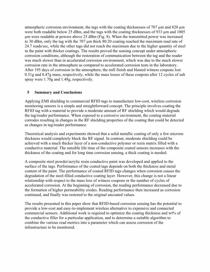
Equation (1) shows that shielding materials with high electrical conductivities have a correspondingly high shielding effectiveness. While mobile charge carriers (electrons or electron holes) in the shielding material are required to reflect radiation,10-12 some lower conductivity materials such as polymer composites containing conductive fillers are also suitable for EMI shielding, depending on the thickness and application.10-14 Fig. 1 illustrates the shielding effectiveness calculated from Equation (1) for different thicknesses of a sheet of AISI 1010 carbon steel (Fig. 1a) and a theoretical steel-filled conductive paint with a volume fraction of 50% steel particles with an average particle size of 100 m, dispersed in an epoxy resin (Fig. 1b) at a common frequency of 915 MHz. The relative conductivity of the carbon steel compared to copper is 0.12, while that of the steel-filled paint was calculated to be on the order of 2.6×10⁻⁵
using a model developed by Mamunya et al.,15 which is four orders of magnitude lower than solid steel. The relative permeability of both materials was assumed to be 1.0, since at high frequencies this value tends towards unity.16
Fig. 1a shows that at a thickness of only 8 μm, a shield made of sheet steel, which has an electrical conductivity of 6.99×10⁶ S·m-1,17 would attenuate the RF signal by more than 80 dB, or 99.999 999%, where the power attenuation, or shielding effectiveness, is given by Es = 10 log(Powerout/Powerin). In contrast, for the theoretical steel-filled composite coating with a calculated electrical conductivity of about 1500 S·m-1,15 it was calculated that the coating thickness required to have the same signal attenuation of 80 dB would be 2332 μm. Fig.1b also illustrates that a change in the composite coating thickness of ±100 µm would only change the attenuation by about ± 2 dB. For many applications, a shielding effectiveness on the order of 99.99% (40 dB) is considered to be sufficient.12,14 Thus, for this theoretical paint, a coating thickness on the order of 360 μm would be required to achieve this attenuation.
As shown in Part I of this paper,8 a thin (25 μm) steel foil had strong EMI shielding effectiveness as demonstrated by complete blockage of the signal between the tag and reader, but the foil corroded relatively quickly such that there was a rapid decline in its shielding ability. Thus, for long term cumulative corrosion monitoring, an EMI layer with controllable shielding effectiveness and slower corrosion rate would be desired for practical applications. The properties of metal-filled conductive paint can be readily altered by changing the filler material’s composition, concentration, or morphology, and therefore could be custom designed for a particular application, making it a potential candidate for an EMI shielding layer for an RFID corrosion sensor.
3 Materials and Methods
3.1 Evaluation of Alternative EMI Shielding Technologies
RFID tags are normally manufactured with plastic enclosures to protect the chip and antenna. To use commercial RFID tags as corrosion sensors, an EMI shield has to be applied onto the plastic enclosures. Conventional metal coating techniques such as chemical vapor deposition, thermal spray, and electrodeposition often rely on high application temperatures or electrical conductivity of the substrate, both of which would be difficult with plastics. Although a number of techniques such as electroless plating and chemical activation plus electrolytic plating exist for plastic metallization, the film produced is usually very thin and is not sufficiently robust for the current application. A number of other plastic metallisation technologies were investigated and evaluated, including plasma spray, magnetron sputtering, composite metal spray, and electrostatic powder coating. Adhesion of steel to the plastic substrate applied by plasma spray and magnetron sputtering was poor. The iron based coating applied by composite metal spray was non-conductive and ineffective as an EMI shield. Coatings applied by electrostatic powder spray were not sufficiently uniform, particularly at high iron concentrations, which was likely due to the large difference in density between the iron powder and epoxy matrix. Conductive paint spray seemed to be the most promising method and was thus studied further.
3.1.1 Selection of Filler Metals for Conductive Paint
There are numerous types of EMI shielding paints commercially available with conductive fillers of copper, silver, or nickel which can be applied with conventional paint spray equipment. However, many of these are designed to have good corrosion resistance, which is contrary to the requirements in a corrosion monitoring application. An iron-based powder filler would be desirable for the corrosion sensor since it would have similar corrosion characteristics to the vehicle bodies. However, this type of paint was not commercially available, thus it was necessary to custom prepare one in the laboratory.
Two commercially available iron-based metal powders were initially selected as the filler material: AISI 4340 steel powder (Carpenter Technology Corp., Wyomissing, PA), which is typically used for powder metallurgy applications; and Atomet 195SP (Rio Tinto Metal Powders, Sorel-Tracy, QC) which is a high purity iron powder typically used for food and feed enrichment. The chemical compositions and average particle sizes of the two powders are given in Table 1. Although it was preferable to use steel powders with identical composition to the steel used in the vehicle being monitored (e.g. mild steel), those alloys are rarely manufactured in powder form and were difficult to obtain. On the other hand, even if mild steel powders were used in the paint, the corrosion behavior would still likely be somewhat different from the steel sheet or plate normally used in the vehicle, due to the forming and heat treatment processes. Thus, the filler material was selected based on two fundamental properties: a) ability to provide an EMI shielding effect, and b) ability to readily corrode in corrosive environments.
The two metal powders were used in their as-supplied state, without any additional cleaning or processing, and were mechanically mixed with an Opex acrylic resin (Sherwin-Williams, Cleveland, OH) at three powder to acrylic ratios: 50:50, 75:25, and 80:20 wt%. (Unless otherwise stated, all powder to acrylic ratios in this paper are given in wt%.) Paints with higher powder to acrylic ratios of >90:10 showed poor adhesion to the substrate, and extensive delamination of the coating from the substrate after only 12 accelerated corrosion test cycles; they were not explored further. The acrylic resin was selected because it was supplied as a lacquer integrated with a binder and could be readily applied using conventional spray devices. In addition, acrylic has low UV sensitivity and good weather resistance, and is thus suitable for the current application. The conductive paints were applied to the top surface of RFID tags using a high volume low pressure (HVLP) spray gun. It was difficult to obtain consistent coating thicknesses between tags, and thus only a single tag was created for each thickness for a given paint composition.
The coatings were evaluated based on the ease of application and the shielding effectiveness. Samples of the coating were sectioned, polished, and the microstructure examined with a scanning electron microscope (SEM).
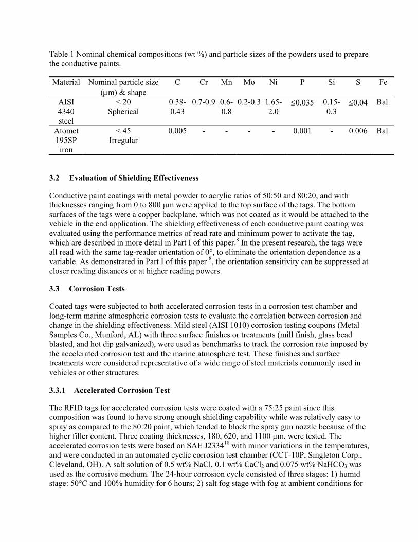
Table 1 Nominal chemical compositions (wt %) and particle sizes of the powders used to prepare the conductive paints.
Material Nominal particle size (m) & shape
C Cr Mn Mo Ni P Si S Fe
AISI 4340 steel
< 20 Spherical
0.38-0.43
0.7-0.9 0.6-0.8
0.2-0.3 1.65-2.0
0.035 0.15-0.3
0.04 Bal.
Atomet 195SP iron
< 45 Irregular
0.005 - - - - 0.001 - 0.006 Bal.
3.2 Evaluation of Shielding Effectiveness
Conductive paint coatings with metal powder to acrylic ratios of 50:50 and 80:20, and with thicknesses ranging from 0 to 800 µm were applied to the top surface of the tags. The bottom surfaces of the tags were a copper backplane, which was not coated as it would be attached to the vehicle in the end application. The shielding effectiveness of each conductive paint coating was evaluated using the performance metrics of read rate and minimum power to activate the tag, which are described in more detail in Part I of this paper.8 In the present research, the tags were all read with the same tag-reader orientation of 0°, to eliminate the orientation dependence as a variable. As demonstrated in Part I of this paper 8, the orientation sensitivity can be suppressed at closer reading distances or at higher reading powers.
3.3 Corrosion Tests
Coated tags were subjected to both accelerated corrosion tests in a corrosion test chamber and long-term marine atmospheric corrosion tests to evaluate the correlation between corrosion and change in the shielding effectiveness. Mild steel (AISI 1010) corrosion testing coupons (Metal Samples Co., Munford, AL) with three surface finishes or treatments (mill finish, glass bead blasted, and hot dip galvanized), were used as benchmarks to track the corrosion rate imposed by the accelerated corrosion test and the marine atmosphere test. These finishes and surface treatments were considered representative of a wide range of steel materials commonly used in vehicles or other structures.
3.3.1 Accelerated Corrosion Test
The RFID tags for accelerated corrosion tests were coated with a 75:25 paint since this composition was found to have strong enough shielding capability while was relatively easy to spray as compared to the 80:20 paint, which tended to block the spray gun nozzle because of the higher filler content. Three coating thicknesses, 180, 620, and 1100 µm, were tested. The accelerated corrosion tests were based on SAE J233418 with minor variations in the temperatures, and were conducted in an automated cyclic corrosion test chamber (CCT-10P, Singleton Corp., Cleveland, OH). A salt solution of 0.5 wt% NaCl, 0.1 wt% CaCl2 and 0.075 wt% NaHCO3 was used as the corrosive medium. The 24-hour corrosion cycle consisted of three stages: 1) humid stage: 50°C and 100% humidity for 6 hours; 2) salt fog stage with fog at ambient conditions for
15 minutes; 3) dry stage: 50°C and 50% humidity for 17 hours 45 minutes. The tags and metal coupons were subjected to a total of 60 24-hour cycles, and the RFID tag readings and the coupon masses were recorded at 12-cycle intervals. The mass loss of the coupons was evaluated in accordance with ASTM G119.
After the reading performance measurements were completed, the tags were sectioned, mounted, polished and the microstructure of the cross sections were examined with an SEM (Nova NanoSEM, FEI, Hillsboro, OR). Energy dispersive X-ray Spectrometry (EDS) spectra were obtained at various points on the cross section to determine chemical compositions of the corroded coating.
3.3.2 Marine Atmosphere Corrosion Test
The marine atmospheric corrosion test was conducted outdoors at a marine coastal site located at Victoria, British Columbia, Canada. The site was typical of coastal sites experiencing industrial pollution with corrosive elements in the atmosphere consisting mainly of chlorides (Cl-) and sulphates (SO4
2-).20, 21 Two paint compositions, 75:25 and 80:20, were used for the marine atmosphere corrosion tests. The RFID tags and test coupons were mounted on the exposure site, which faces south towards the Strait of Juan de Fuca, approximately 5 m above and 3 m horizontally from the water edge and left exposed starting in October 2011. The tags were oriented approximately 60 degrees from horizontal. This test was long term subject to the normal weather variability and corrosion was not considered to be aggressive. In May 2012, after a total of 195 days of exposure, the read rates of the tags were measured.
4 Results and Discussion
4.1 Evaluation of Conductive Filler Material
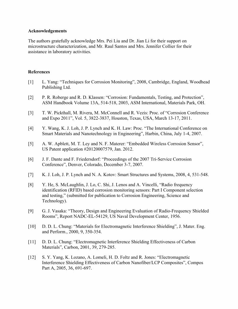
Visually, the tags with the iron-filled paint had a rougher surface finish than those coated with steel-filled paint, likely due to a combination of the larger particle sizes and irregular particle shapes of the iron (Fig. 2). Although asymmetric filler particles are reported to be more effective in increasing the electrical conductivity than spherical powders,11 they were found to be more difficult to apply by the spray process, as the particles tended to block the spray gun nozzle. Fig. 2 also illustrates how the finer particle size of the steel-based coating results in a better connectivity between the conductive particles, which should give rise to a better shielding effect. In addition, with a finer particle size, there are more individual particles at a given powder to acrylic ratio, further increasing the shielding effectiveness. Because of the advantages of the spherical shapes and smaller particle sizes in the steel-filled paints, and the difficulty of application of iron-filled paints, the iron-filled paints were not studied further or included in the corrosion tests.
4.2 Shielding Effectiveness of Uncorroded Coatings
Equation (1) shows that the shielding effectiveness of the coating is mainly dependent on the electrical conductivity and the thickness. The conductivity of the paint can be readily manipulated through variations in the weight ratios of steel powder to acrylic resins and the particle size and shape.
The shielding effectiveness for the steel-filled paint generally increased with an increase in both coating thickness and metal content, as indicated by a decrease in read rate at a given power level. With the 50:50 paint (Fig. 3a), a coating thickness of 250 μm provided sufficient shielding to reduce the read rate to zero at 15 dBm, and when the power was increased to 20 dBm, a thickness of 500 μm was required to completely block communication between the tag and reader. Power levels of 25 dBm and above were not completely blocked with any of the coating thicknesses tested up to 700 μm. Due to the very low shielding effectiveness of the 50:50 paint at all thicknesses tested, this composition was not selected for further study.
Increasing the metal content to 80 wt% (Fig. 3b) resulted in a reduction of the read rates at all power levels and coating thicknesses tested. However, even when the coating thickness of the 80:20 paint was increased to 1.5 mm, the signal at the highest transmitted power of 30 dBm was not completely blocked, and a read rate of 20 reads/sec was obtained (data not shown), but this was a considerable improvement over the 50:50 paint. This incomplete shielding is thought to be because the steel particles are dispersed in the polymer matrix with weak connectivity, thus the electrical conductivity of the 80:20 paint (<1.0 S·m-1 in our coatings, as measured by a Lucas Signatone Pro-4 four-probe resistivity measurement system) is much less than solid steel (6.67×10⁶ S·m-1, as measured by the same system). As a result, the EMI shielding effectiveness of the paint is much lower, and even with thick coating layers the RF signal is not completely blocked at high transmitted power levels. We capitalized on this incomplete shielding, since it allows for the establishment of a baseline reading on newly coated tags. Any subsequent reduction in the coating thickness or changes in the coating chemistry and physical connectivity of the steel particles due to corrosion damage will be reflected in changes in reading performance relative to this baseline.
4.3 Corrosion Tests
4.3.1 Accelerated Corrosion Test
Fig. 4 shows the appearance of the tags and witness coupons, and mass loss of the coupons after 60 cycles of accelerated corrosion testing. Visual examination showed that both the witness coupons and the sensor tags underwent severe corrosion (Figs. 4a and 4b). The mass loss of the witness coupons showed an approximately linear relationship with the number of corrosion cycles; the slopes (corrosion rates) were similar for the mill finish and glass bead blasted coupons, while the galvanized coupons showed a much lower corrosion rate (Fig. 4c).
Figs. 5a-5c show the read rates of three sensor tags coated with a 75:25 paint with initial thicknesses of 180, 620, and 1100 μm, before corrosion and after each 12 cycle interval of accelerated corrosion testing. In each of these plots, the minimum reading power shown is the power required to activate the tag, and the read power was incremented by a step size of 0.25 dBm. The read tests do not extend to the full power of 30 dB, as they were stopped shortly after some signal was obtained. The minimum activation power is highly dependent on the coating thickness, with more power required for the thicker coatings. The uncoated tags could all be activated with a power of 10 dBm, which is the lower limit of the reader, at a distance of 75 cm (as shown in Part I of this paper 8). When the tags were coated with 180 µm, 620 µm, and 1100 µm thick conductive paints, the initial (0 cycle in Fig. 5) minimum transmitted powers to operate the tags at a distance of 75 cm were 11.5, 15, and 18 dBm, respectively. The powers needed to
reach the maximum read rate of 24.7 reads/sec varied among the three coating thicknesses prior to corrosion. For the 180 µm coating, the maximum read rate was reached when the read power was 13.75 dBm, indicating that the coating showed very little shielding effectiveness. With the thicker coatings, considerably higher read powers were required to reach the maximum read rates (22 dBm for 620 µm, and 25.5 dBm for 1100 µm), indicating the influence of coating thickness on shielding effectiveness.
The minimum transmitted power required to activate the tag increased after each of the first two measurement intervals (12 and 24 corrosion cycles). This was particularly evident on the tag with the 1100 µm thick coating, where the minimum power required increased by approximately 3 and 4 dBm after 12 and 24 corrosion cycles respectively (Figs. 5c and 5d). After 48 corrosion cycles, the minimum power required to activate the tags decreased gradually with the increasing number of corrosion cycles, indicating the restoration of the communication between the sensors and the reader as corrosion continued.
This initial increase in the minimum transmitted power is contrary to the hypothesis that an immediate increase in the signal strength would occur with the onset of the degradation of the coating layer by corrosion. A possible reason for the initial increase in shielding effectiveness of the painted tags is the increase of the magnetic permeability of the filler powders due to the formation of the ferrous oxides, such as Fe3O4, which has considerably higher magnetic permeability than steel and provides magnetic dipoles for the shielding layer10,11. According to Equation (1), the absorption loss is a function of the product σr μr, whereas the reflection loss is a function of the quotient rr / . The increase of the permeability causes both an increase in the absorption loss and a decrease in the reflection loss. The result is an initial increase in the shielding effectiveness at the beginning of the corrosion tests (as noted in Fig. 5d), with an eventual decrease in effectiveness once the effect of the absorption losses exceeds the reflection losses. Thus, there is a non-linear relationship between the corrosion rate and the signal strength, making the correlation between the corrosion of the metal object and the sensor readings somewhat complicated.
In Part I of this paper,8 this phenomenon of an initial increase in the minimum power was not observed with the metallic foil shields. It is thought that this may be due in part to the rapid corrosion of the foils coupled with long intervals between measurements, and thus, if the phenomenon occurred, it may have been between measurements and was not observed. Also, the tags were initially unreadable at any of the powers tested, and any increase in the shielding effectiveness could not be measured.
Fig. 5d shows the sensor response with the minimum powers required to activate the sensors plotted against the number of corrosion cycles. Since the mass loss of both mill finished and glass bead blasted metal witness coupons had a nearly linear relationship with the number of corrosion cycles, the mass loss was appropriately scaled and was superimposed on the x-axis. In this way, the sensor output was indirectly correlated to the degree of corrosion attack of the material to be monitored. The initial coating thickness essentially determines the sensible life time of the RFID sensor in a corrosive environment. For example, the thinnest coating of 180 m only had a shielding effect for about 48 cycles of corrosion, since at this point, the sensor output had been restored to almost the same level as without a coating. Further corrosion on the coating material could not be sensed beyond 48 cycles since the coating material had lost nearly all of its
EMI shielding capability. Thus for long-term corrosion monitoring, it would appear that thick coatings are preferable. Another advantage of the thicker coatings is the clear delineation between corrosion cycles in the read rates at various power levels. Compared to the thinner coating in Figs. 5a and 5b, the 1100 μm thick coating (Fig. 5c) does not show overlap at the lower read rates or power levels. Thus, it is considerably easier to determine where in the corrosion process this tag would be, and to assess the potential amount of damage on the structure that it is monitoring.
Fig. 6 shows SEM micrographs of a cross-section of the tag coating and elemental analysis obtained via EDS after 24 cycles of corrosion. The initial thickness of the coating in Fig. 6 was 980 μm, but following corrosion it was 1500 μm. The thickness of the coating increased in part due to the formation of oxides, as well as laminar cracks. Transverse cracks were also observed perpendicular to the coating surface (Fig. 6a). The corrosion of the paint started from the exposed surfaces of the steel particles and penetrated inwards. The EDS analysis in Fig. 6c indicates that most of the steel particles were converted to oxides and chlorides, as indicated by the gray color in locations B and C in Fig. 6b, with very few particles remaining that were not attacked (indicated by the white regions such as location A in Fig. 6b). The formation of various oxides/chlorides and other substances resulted in the expansion in dimension of the steel particles dispersed in the acrylic matrix (Fig. 6d), which would increase the connectivity between the particles. As a result, the shielding effectiveness of the coating may increase, which may have contributed to the initial increase of the shielding capability. As the corrosion continues, the decrease of electrical conductivity appears to dominate over the hypothesised increase in magnetic permeability, resulting in the overall decrease of the coating’s shielding capability. This is manifested by an increase in the tag performance, as determined by the metrics of read rate and minimum read power.
As demonstrated on the continuous metal layers in Part I of this paper,8 corrosion significantly decreased their shielding abilities. It is assumed that this reduction in shielding ability is due to the considerable formation of oxides which have a lower conductivity than the base material.22 The shielding abilities of the conductive paints however, are considerably lower than the continuous metal layers. With a density on the order of 7.85g/cm3, the steel powder is much heavier than that of the paint resin at 1.18g/cm3, which means that even at 75 wt% steel powder in the paint, the volume fraction is only about 30%. Consequently, conductivity of the steel powder filled paint is about 5 or 6 orders of magnitude lower than solid steel (as measured by the four-probe system). Thus the composite paint coating has a considerably lower shielding capability even if very thick coating layer was applied.
4.3.2 Atmospheric Corrosion Test
Figs. 7a and 7b show the tags before and after atmospheric corrosion testing, respectively. The appearance of these tags is different from those after 60 cycles of accelerated corrosion (Fig. 4b). While the corrosion product on the surfaces of atmospherically corroded samples was primarily reddish-brown ferric oxide that is typical of most rusted surfaces, the accelerated corrosion samples had areas of dark gray products in addition to the typical brown rust. This was due to the different corrosion conditions (corrosive media, temperature, humidity, etc.) in the two testing environments. After coating but before corrosion, none of the tags were readable at a transmitted power of 25 dBm, but were all readable at 30 dBm. After 195 days of exposure to the
atmospheric corrosion environment, the tags with the coating thicknesses of 707 µm and 820 µm were both readable below 25 dBm, and the tags with the coating thicknesses of 933 µm and 1005 µm were readable at powers above 25 dBm (Fig. 8). When the transmitted power was increased to 30 dBm, only the tag with the 707 µm thick 80:20 coating reached the maximum read rate of 24.7 reads/sec, while the other tags did not reach the maximum due to the higher quantity of steel in the paint with thicker coatings. The results proved the sensing concept under atmospheric corrosion conditions, although the restoration of communication between the tag and the reader was much slower than in accelerated corrosion environment, which was due to the much slower corrosion rate in the atmosphere as compared to accelerated corrosion tests in the laboratory. After 195 days of corrosion in the atmosphere, the mill finish and blasted witness coupons lost 0.51g and 0.47g mass, respectively, while the mass losses of these coupons after 12 cycles of salt spray were 1.70g and 1.48g, respectively.
5 Summary and Conclusions
Applying EMI shielding to commercial RFID tags to manufacture low-cost, wireless corrosion monitoring sensors is a simple and straightforward concept. The principle involves coating the RFID tag with a material to provide a moderate amount of RF shielding which would degrade the tag/reader performance. When exposed to a corrosive environment, the coating material corrodes resulting in changes in the RF shielding properties of the coating that could be detected as changes in tag/reader performance.
Theoretical analysis and experiments showed that a solid metallic coating of only a few microns thickness would completely block the RF signal. In contrast, moderate shielding could be achieved with a much thicker layer of a non-conductive polymer or resin matrix filled with a conductive material. The sensible life time of the composite coated sensors increases with the thickness of the coating and for long time corrosion sensing, a thick coating is needed.
A composite steel powder/acrylic resin conductive paint was developed and applied to the surface of the tags. Performance of the coated tags depends on both the thickness and metal content of the paint. The performance of coated RFID tags changes when corrosion causes the degradation of the steel-filled conductive coating layer. However, this change is not a linear relationship with respect to the mass loss of witness coupons or the number of cycles of accelerated corrosion. At the beginning of corrosion, the reading performance decreased due to the formation of higher permeability oxides. Reading performance then increased as corrosion continued, and finally was restored to the original uncoated values.
The results presented in this paper show that RFID-based corrosion sensing has the potential to provide a low-cost and easy-to-implement wireless alternative to expensive and connected commercial sensors. Additional work is required to optimize the coating thickness and wt% of the conductive filler for a particular application, and to determine a suitable algorithm to combine the various read metrics into a parameter which can assess corrosion of the infrastructure to be monitored.
Acknowledgements
The authors gratefully acknowledge Mrs. Pei Liu and Dr. Jian Li for their support on microstructure characterization, and Mr. Raul Santos and Mrs. Jennifer Collier for their assistance in laboratory activities.
References
[1] L. Yang: “Techniques for Corrosion Monitoring”, 2008, Cambridge, England, Woodhead Publishing Ltd.
[2] P. R. Roberge and R. D. Klassen: “Corrosion: Fundamentals, Testing, and Protection”, ASM Handbook Volume 13A, 514-518, 2003, ASM International, Materials Park, OH.
[3] T. W. Pickthall, M. Rivera, M. McConnell and R. Vezis: Proc. of “Corrosion Conference and Expo 2011”, Vol. 5, 3822-3837, Houston, Texas, USA, March 13-17, 2011.
[4] Y. Wang, K. J. Loh, J. P. Lynch and K. H. Law: Proc. “The International Conference on Smart Materials and Nanotechnology in Engineering”, Harbin, China, July 1-4, 2007.
[5] A. W. Apblett, M. T. Ley and N. F. Materer: “Embedded Wireless Corrosion Sensor”, US Patent application #20120007579, Jan. 2012.
[6] J. F. Dante and F. Friedersdorf: “Proceedings of the 2007 Tri-Service Corrosion Conference”, Denver, Colorado, December 3-7, 2007.
[7] K. J. Loh, J. P. Lynch and N. A. Kotov: Smart Structures and Systems, 2008, 4, 531-548.
[8] Y. He, S. McLaughlin, J. Lo, C. Shi, J. Lenos and A. Vincelli, “Radio frequency identification (RFID) based corrosion monitoring sensors: Part I Component selection and testing,” (submitted for publication to Corrosion Engineering, Science and Technology).
[9] G. J. Vasaka: “Theory, Design and Engineering Evaluation of Radio-Frequency Shielded Rooms”, Report NADC-EL-54129, US Naval Development Center, 1956.
[10] D. D. L. Chung: “Materials for Electromagnetic Interference Shielding”, J. Mater. Eng. and Perform., 2000, 9, 350-354.
[11] D. D. L. Chung: “Electromagnetic Interference Shielding Effectiveness of Carbon Materials”, Carbon, 2001, 39, 279-285.
[12] S. Y. Yang, K. Lozano, A. Lomeli, H. D. Foltz and R. Jones: “Electromagnetic Interference Shielding Effectiveness of Carbon Nanofiber/LCP Composites”, Compos Part A, 2005, 36, 691-697.
[13] C. Morari, I. Balan, J. Pintea, E. Chitanu and I. Iordache: “Electrical Conductivity and Electromagnetic Shielding Effectiveness of Silicone Rubber Filled with Ferrite and Graphite Powders”, Progress in Electromagnetics Research M, 2011, 21, 93-104.
[14] M. H. Al-Saleh and U. Sundararaj: “Electromagnetic Interference Shielding Mechanisms of CNT/Polymer Composites”, Carbon, 2009, 47, 1738-1746.
[15] Y. P. Mamunya, V. V. Davydenko, P. Pissis and E. V. Lebedev: “Electrical and Thermal Conductivity of Polymers Filled with Metal Powders”, European Polymer Journal, 2002, 38, 1887-1897.
[16] K. K. T. Chung and L. M. Leung: “Conductive Coatings/Gaskets for EMI Shielding: Theory and Practice”, ITEM, 1987.
[17] ASM International Handbook Committee: “Properties and Selection: Irons, Steels, and High-Performance Alloys”, ASM Handbook, Vol. 1, 1990, 195-199, ASM International, Materials Park, OH.
[18] SAE International: “Laboratory Cyclic Corrosion Test”, Standard J2334_200312, 2003.
[19] ASTM International Committee G01 on Corrosion of Metals: “ASTM Standard G1-03, Standard Practice for Preparing, Cleaning, and Evaluating Corrosion Test Specimens”, 2003, 18-26, ASTM International, West Conshohocken, PA.
[20] ASM International Handbook Committee: “Corrosion: Environments and Industries”, ASM Handbook, Vol. 13C, 2006, 27-57, ASM International, Materials Park, OH.
[21] E. Stetton, K. Poplawski and Connie Ma: “Analysis of Sulfur Dioxide Levels – James Bay Neighbourhood 2012”, Report to “British Columbia Ministry of Environment”, 2013, 1-55.
[22] M. Morcillo, D. de la Fuente, I. Diaz and H. Cano: “Atmospheric Corrosion of Mild Steel”, REVISTA DE METALURGIA, 2011, 47, 426-444.
Figures
Fig. 1 EMI shielding effectiveness calculated via Equation (1) vs. coating thickness: (a) C1010 carbon steel, and (b) steel-filled paint. Note the different scales on both the x- and y-axes.
Fig. 2 SEM images of cross sections of RFID tag coatings showing coating microstructure for (a) iron-filled coating, and (b) steel-filled coating. Note different magnifications.
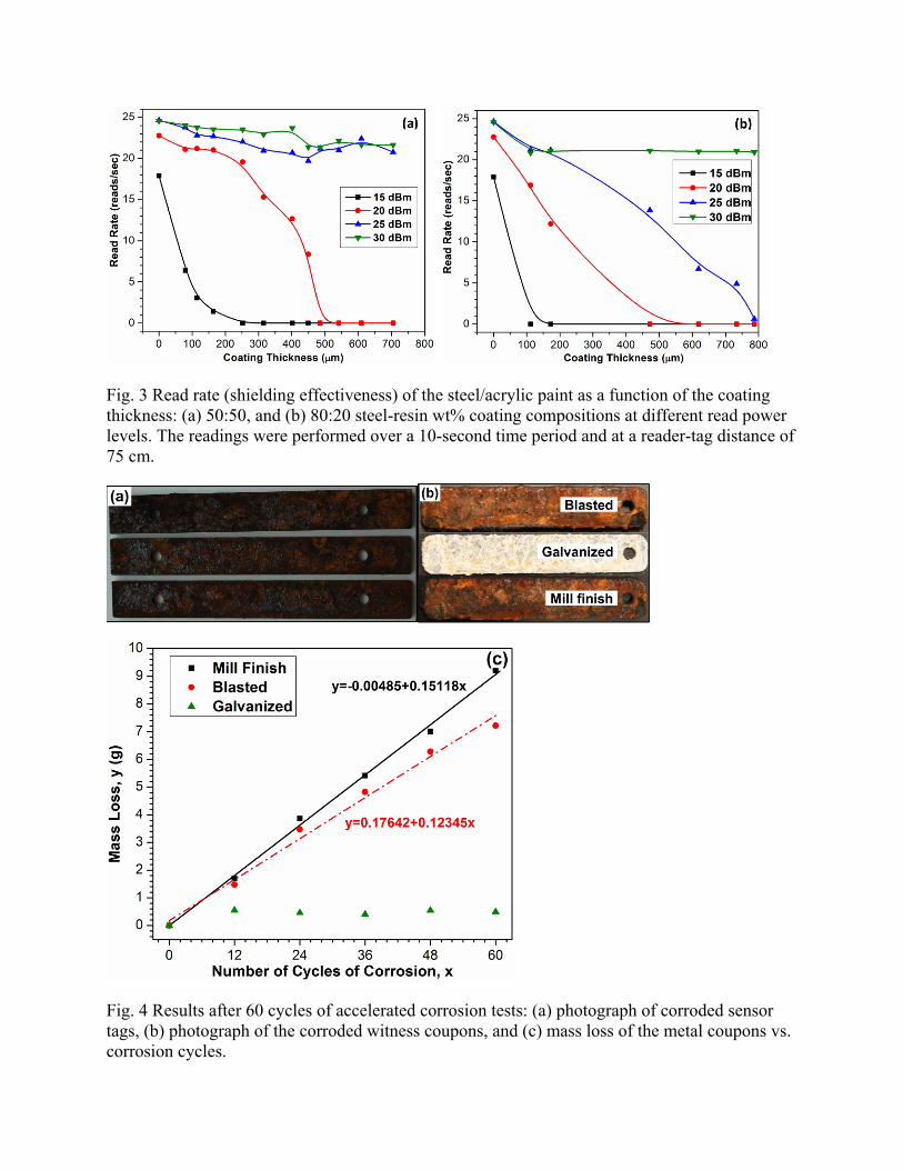
Fig. 3 Read rate (shielding effectiveness) of the steel/acrylic paint as a function of the coating thickness: (a) 50:50, and (b) 80:20 steel-resin wt% coating compositions at different read power levels. The readings were performed over a 10-second time period and at a reader-tag distance of 75 cm.
Fig. 4 Results after 60 cycles of accelerated corrosion tests: (a) photograph of corroded sensor tags, (b) photograph of the corroded witness coupons, and (c) mass loss of the metal coupons vs. corrosion cycles.
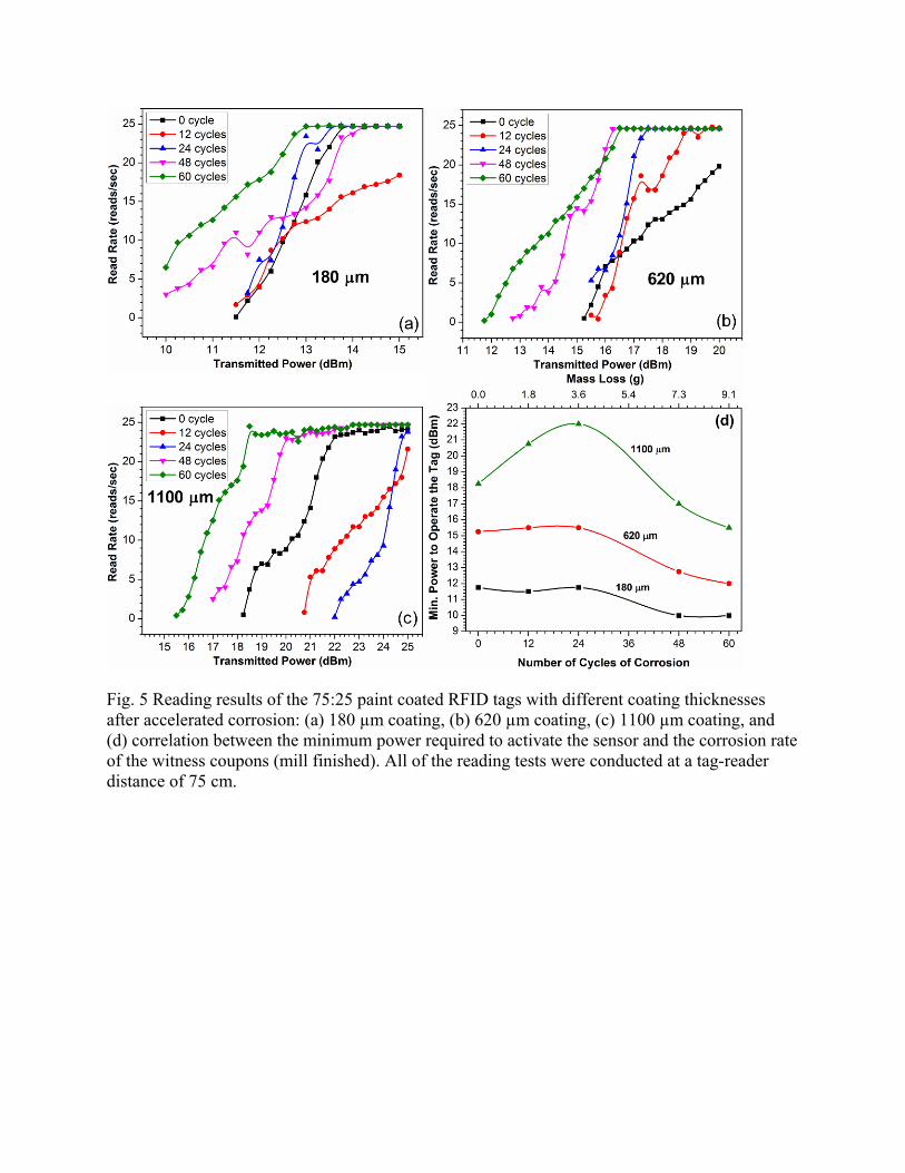
Fig. 5 Reading results of the 75:25 paint coated RFID tags with different coating thicknesses after accelerated corrosion: (a) 180 µm coating, (b) 620 µm coating, (c) 1100 µm coating, and (d) correlation between the minimum power required to activate the sensor and the corrosion rate of the witness coupons (mill finished). All of the reading tests were conducted at a tag-reader distance of 75 cm.
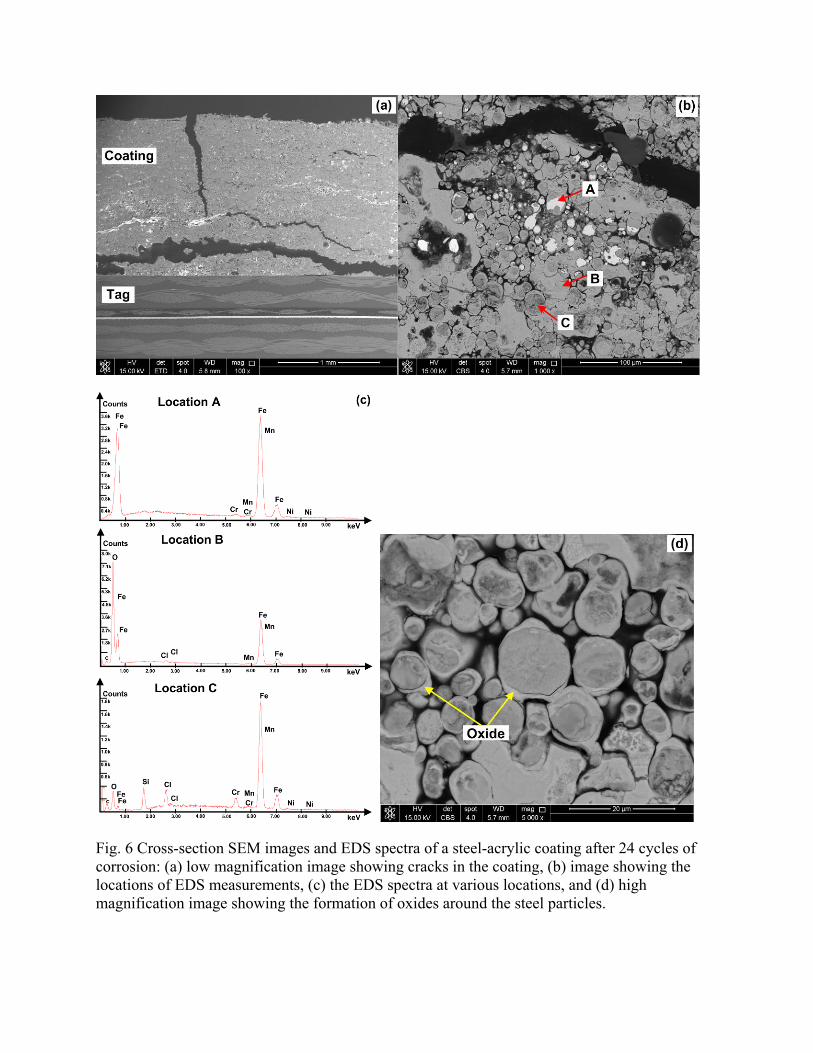
Fig. 6 Cross-section SEM images and EDS spectra of a steel-acrylic coating after 24 cycles of corrosion: (a) low magnification image showing cracks in the coating, (b) image showing the locations of EDS measurements, (c) the EDS spectra at various locations, and (d) high magnification image showing the formation of oxides around the steel particles.
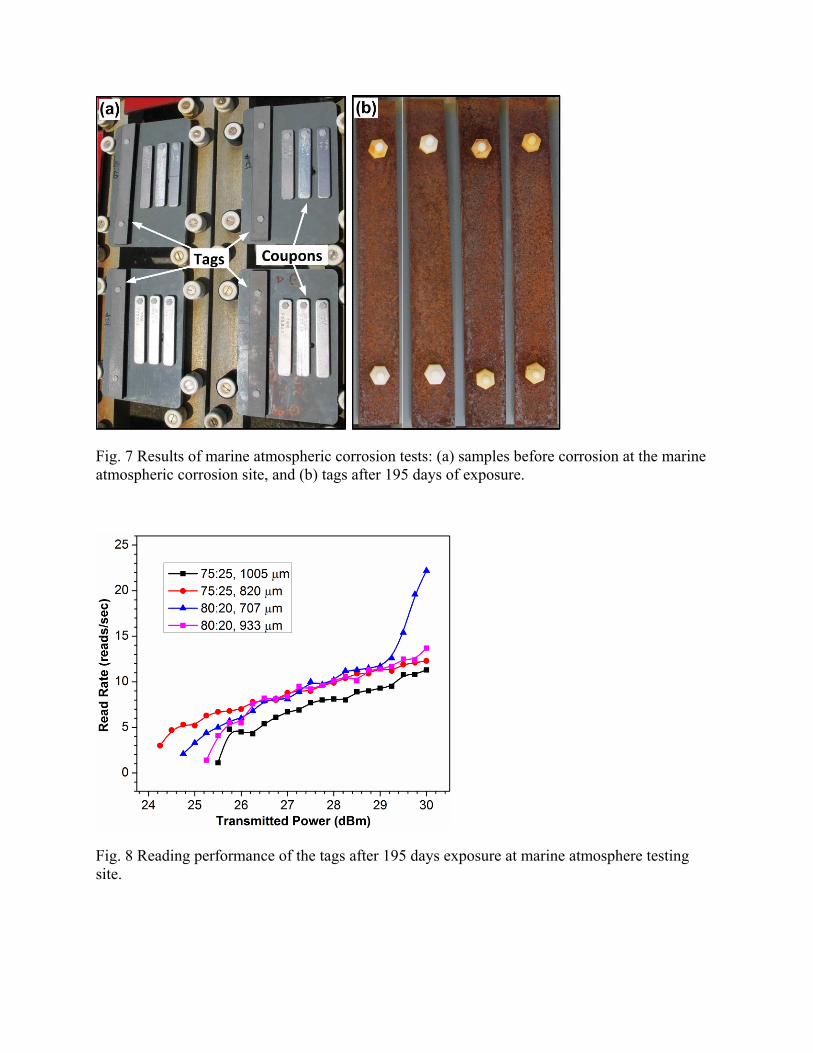
Fig. 7 Results of marine atmospheric corrosion tests: (a) samples before corrosion at the marine atmospheric corrosion site, and (b) tags after 195 days of exposure.
Fig. 8 Reading performance of the tags after 195 days exposure at marine atmosphere testing site.