rf cookbook - part i description - wiki.scn.sap.com · version: 2.3 release:1.0 author: sap...
TRANSCRIPT

Version: 2.3
Release: 1.0
Author: SAP Development
RF Cookbook - Part IDescription
History
Version Status Date1.0 2003-10-021.1 2003–11–171.2 2004–01–27
2.0 After workshop 2004–05–07
2.1 Revised 2006–10–26
2.2 Revised 2008–03–14
2.3 Revised 2016-05-02

Contents
1 Objective ............................................................................................... 51.1 Architecture Description of the RF Framework................................................. 51.2 RF Runtime – Framework Interaction Model .................................................... 61.3 RF Framework Customizing Overview ............................................................. 81.4 Sending Messages to Working Resources ...................................................... 9
2 RF Framework .................................................................................... 142.1 Structure ........................................................................................................ 142.2 Important Tables and Structures .................................................................... 142.3 Important Classes .......................................................................................... 142.4 Debugging ..................................................................................................... 142.4.1 Breakpoints ........................................................................................................................142.4.1.1 Method /SCWM/CL_RF_BLL_SRVC=>CALL_FLOW_PROCESS................................142.4.1.2 Method /SCWM/CL_RF_BLL_SRVC=>GET_STEP_FLOW ..........................................152.4.1.3 Method /SCWM/CL_RF_BLL_SRVC=>RUN ..................................................................152.4.1.4 Method /SCWM/CL_RF_BLL_SRVC=>DISPLAY_STEP ...............................................152.4.1.5 Method /SCWM/CL_RF_BLL_SRVC=>CHECK_VERIF_PRF.......................................152.4.2 Breakpoint IDs....................................................................................................................15
3 RF Cookbook ...................................................................................... 163.1 Application Definition ..................................................................................... 163.2 Presentation Profile Definition ........................................................................ 163.3 Display Profile Definition ................................................................................ 163.3.1 Template Screens ..............................................................................................................173.3.1.1 Template Screen Title .......................................................................................................173.3.2 Message Handling .............................................................................................................173.4 Personalization Profile Definition ................................................................... 183.5 Define Logical Transaction ............................................................................ 183.6 Assign Text to Logical Transaction and Other Objects ................................... 193.7 Create Menu Item .......................................................................................... 203.8 Assign Text to Menu Item .............................................................................. 203.9 Create Menu Hierarchy Including Submenus and Transactions ..................... 203.10 Define Logical Transaction Steps .................................................................. 203.11 Define Initial Step for Logical Transaction ...................................................... 213.12 Define Application Data Containers ............................................................... 213.12.1 Using Tables in the RF Framework ..................................................................................223.13 Create Template Screen ................................................................................ 223.13.1 Use Custom Template Dynpro .........................................................................................223.14 Create Subscreens ........................................................................................ 233.14.1 Predefined Screen Groups................................................................................................243.14.1.1 Group 1 ...............................................................................................................................24

3.14.1.2 Group 3 ...............................................................................................................................243.14.2 Automatic Page Up / Page Down Implementation ..........................................................243.14.3 Field to Field Navigation ....................................................................................................253.14.3.1 Navigation Between Verification Fields ............................................................................253.14.3.2 Navigation Between Input Fields (No Verification Fields) ...............................................253.14.3.3 Navigation on a Screen with Input Fields and Verification Fields ..................................263.14.4 Exiting a Screen Without Saving Data in Internal Structures .........................................263.14.5 Exiting a Screen and Saving Data in Internal Structures ................................................263.14.6 Exiting a Screen and Calling the Content Provider .........................................................263.15 Define Function Code Catalog ....................................................................... 273.15.1 Predefined Function Codes in the RF Framework ..........................................................273.16 Assign Text to Function Code ........................................................................ 283.17 Create Services to Support Business Logic ................................................... 283.18 Define State Catalogue .................................................................................. 293.19 Map Logical Transaction Step to Subscreen .................................................. 293.20 Define Function Code Profile ......................................................................... 303.20.1 GUI Status Is Defined for the Template ...........................................................................313.20.2 Connect Screen Function Codes and RF Framework Function Codes .........................313.20.3 Handle More Function Codes Than Available Pushbuttons on a Screen or Step ........323.21 Define Step Flow ........................................................................................... 333.21.1 PBO of Initial Screen After Menu Selection .....................................................................343.21.2 PAI of Screen and Direct Display of Next Screen ...........................................................343.21.3 PAI of Screen and PBO of Next Screen ..........................................................................343.21.4 Call of Common Screen from Several Screens During Transaction ..............................353.21.5 Customizable ENTER / Set Next Step Dynamically Using the CP ................................353.21.6 Additional Information ........................................................................................................363.22 Set Default Navigation at Transaction End .................................................... 373.23 Set Verification Profile ................................................................................... 373.23.1 Verification ..........................................................................................................................383.24 Presentation Device Catalog ......................................................................... 40
4 Layout ................................................................................................. 414.1 Screen ........................................................................................................... 414.2 Fields ............................................................................................................. 414.2.1 Field Length........................................................................................................................42
5 Programming Information ................................................................. 435.1 Posting .......................................................................................................... 435.2 Exception Handling and Using Shortcuts ....................................................... 435.2.1 Navigation ..........................................................................................................................435.2.2 Exceptions ..........................................................................................................................445.3 Differences .................................................................................................... 445.4 Support LIST Functions ................................................................................. 445.5 Display of Text (from Delivery or Hazardous Material) ................................... 45

5.6 Methods Available to the Content Provider .................................................... 455.6.1 Methods into the Framework ............................................................................................455.6.2 Methods out of the Framework .........................................................................................465.7 Global Variables ............................................................................................ 465.8 Display Technical Data on GUI Title of RF UI ................................................ 475.9 Hard-Coded Logical Transaction ................................................................... 49
6 Using the Tools Provided .................................................................. 516.1 Menu Manager .............................................................................................. 516.2 Screen Manager ............................................................................................ 526.2.1 Create, Copy, and Delete Display Profiles ......................................................................526.2.1.1 Creating a Display Profile ..................................................................................................536.2.1.2 Copying a Display Profile ..................................................................................................536.2.1.3 Guideline for screen conversion .......................................................................................546.2.1.4 Deleting a Display Profile ..................................................................................................546.2.2 Editing Screens of a Display Profile .................................................................................556.2.2.1 Screen Maintenance ..........................................................................................................556.3 Wizards ......................................................................................................... 566.3.1 Split Screen ........................................................................................................................566.3.2 Modify Screen ....................................................................................................................576.3.3 Error Message Handling in RF Wizard.............................................................................57

1 Objective
SAP has developed a new radio frequency (RF) concept.
This RF cookbook helps developers to begin working in the RF framework. Itanswers frequently asked questions and helps to avoid common errors. This RFcookbook also provides some useful tips about the standard layout and screenstructure that should be applied in the standard transactions.
Initially, the RF framework will be used for development in the ExtendedWarehouse Management (EWM) project. However, the RF framework isapplication-independent and could also be used in other projects or applications.
1.1 Architecture Description of the RF Framework
Transaction /SCWM/RFUI is the starting point for all logical RF transactions inEWM. Logical transactions cannot be started directly from the SAP Easy Accessscreen and no equivalent transaction has been created in SE93.
The Easy Enhancement Workbench (EEWB), which can be used for customerenhancements, is integrated into the RF framework. Within the EEWB, usersexecute an RF process and when the modification screen is reached, theenhancement tool is triggered. Users then select the type of enhancement thatthey want to carry out. The appropriate enhancement wizard launches andguides the user through the enhancement process. If the user wants to enhancefields on the user interface, the screen painter is called once the enhancement is

complete so that further adjustments to the screen can be made manually. Thisis part of post processing.
1.2 RF Runtime – Framework Interaction ModelThe RF framework architecture consists of three distinct layers:
1. Dynpro layer2. Business logic layer3. Content provider
The dynpro layer is concerned with all screen-related data, display profiles,presentation devices, subscreens and templates, and so on.
At runtime, the business logic layer receives transactional parameters such asnext step, screen, function code profile, and so on, from the underlyingCustomizing settings.
Content provider stores and supplies the relevant data for processing.
The following sequence diagram shows how these layers interact.

Dynpro LayerObject1
User
Business Logic Layer Content Provider
Invoke Transaction()
Execute Step()
Determine the following step()
Execute FM()
Set presentation parameters & current logical transaction()
Build Function Code Profile()
Build Verification Profile()
Verify fields status and profiles prior to display()
{Next step in background}Execute next step()
Set initial step & function code()
Execute Step()
Execute FM()
Pass presentation data to template and sub-screen()
Execute based on input and function code()
Text A
A
Execute transaction()
Determine next step()
Check verification values()
Check verification values()
Update Stack()
Update Stack()

1.3 RF Framework Customizing OverviewCustomizing for the Radio Frequency (RF) Framework comprises the followingareas:
1. User and resource settings2. Interface parameters and communication structures3. Basic building blocks4. Configuration and scenario assignments
In Customizing (transaction SPRO), the main Customizing activities for the radiofrequency framework are available under Extended Warehouse Management àMobile Data Entry.
The Customizing activity Define Steps in Logical Transaction contains thefollowing submenus:

User and resource settings support the definition of new presentation and personalizationprofiles, which are required to define behavior that varies from standard configuration. Theseprofiles are linked to resource logons, making it possible to define alternative responses (such asdisplaying a user-defined screen instead of the standard screen) for a particular user or usergroup.
Interface parameters and communication structures can be defined for data communicationbetween different screens (dynpros). For more information, see the Define ApplicationParameters option.
Basic building blocks include the definitions of logical transactions, steps, and function codes.
Configuration includes assigning steps to logical transactions and their flow, determiningscreens, assigning function codes, and assigning validations. For more information, see thefollowing sections.
You can call some Customizing activities directly using transaction codes, for example,/SCWM/RFMENU for the RF Menu Manager or /SCWM/RFSCR for the RF Screen Manager.
You can call Presentation Device Maintenance using transaction /SCWM/PRDVC.
1.4 Sending Messages to Working Resources
You can send messages to different resources from the EWM Monitor. To do so,proceed as follows:
1. Call transaction /SCWM/MON.
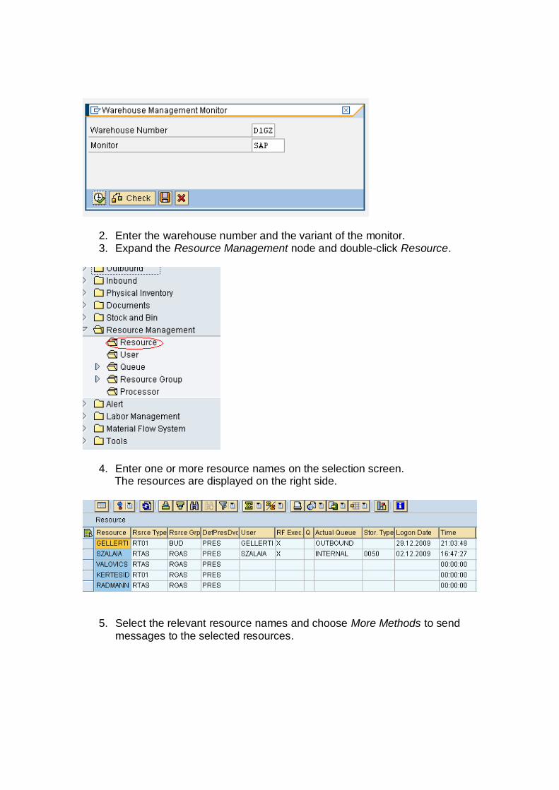
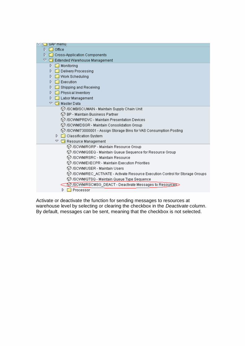
2. Enter the warehouse number and the variant of the monitor.3. Expand the Resource Management node and double-click Resource.
4. Enter one or more resource names on the selection screen.The resources are displayed on the right side.
5. Select the relevant resource names and choose More Methods to sendmessages to the selected resources.

6. Enter the message text in the dialog box and choose Send Message.If the resource is logged on to the RF application, the message isdisplayed.
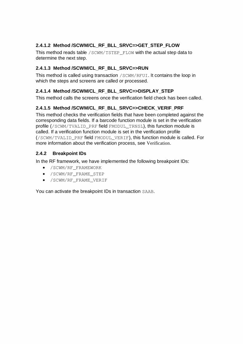
You can deactivate the function for sending and processing RF resourcemessages by calling transaction /SCWM/ RSCMSG_DEACT. Alternatively,choose the following on the SAP Easy Access screen:
Activate or deactivate the function for sending messages to resources atwarehouse level by selecting or clearing the checkbox in the Deactivate column.By default, messages can be sent, meaning that the checkbox is not selected.

Note:
1. If you deactivate the function for sending messages for the warehouse,you cannot send messages to the resource in the monitor. The messagereceipt process is also deactivated in the RF framework. If you attempt tosend a message to the resource in the monitor, the system displays anerror message.
2. When you change the Deactivate field in the Customizing settings, youmust restart the monitor and log in again for the change to be applied tothe resource.

2 RF Framework
2.1 StructureThe RF framework is developed in package /SCWM/RF_FRAMEWORK.
2.2 Important Tables and StructuresTable Description/SCWM/TAPPL_CAT Application, for example, WME/SCWM/TDPRF_CAT Display profile/SCWM/TFCOD_CAT Function code catalog/SCWM/TFCOD_PRF Function code profile/SCWM/TMENU_CAT Menu catalog/SCWM/TMENU_HIER Menu hierarchy/SCWM/TOBJ_TXT Object text/SCWM/TPARAM_CAT Data container/SCWM/TPRDV_CAT Presentation device/SCWM/TPRES_CAT Presentation profile/SCWM/TPRSN_PRF Personalization profile/SCWM/TSTAT_CAT State catalog/SCWM/TSTEP_CAT Steps/SCWM/TSTEP_FLOW Step flow
/SCWM/TSTEP_SCRMapping of foreground steps tosubscreen
/SCWM/TTRNS_CAT Logical transactions
/SCWM/TTRNS_NAVNavigation at end of logicaltransaction
/SCWM/TVALID_PRF Verification and validation profile/SCWM/TVLID_CAT Verification and validation objects
2.3 Important ClassesClass Description/SCWM/CL_RF_BLL_DB Presentation data access/SCWM/CL_RF_BLL_SRVC RF Business Logic Layer
2.4 Debugging
2.4.1 Breakpoints
2.4.1.1 Method /SCWM/CL_RF_BLL_SRVC=>CALL_FLOW_PROCESSThis method calls the function modules defined in /SCWM/TSTEP_FLOW.
2.4.1.2 Method /SCWM/CL_RF_BLL_SRVC=>GET_STEP_FLOWThis method reads table /SCWM/TSTEP_FLOW with the actual step data todetermine the next step.
2.4.1.3 Method /SCWM/CL_RF_BLL_SRVC=>RUNThis method is called using transaction /SCWM/RFUI. It contains the loop inwhich the steps and screens are called or processed.
2.4.1.4 Method /SCWM/CL_RF_BLL_SRVC=>DISPLAY_STEPThis method calls the screens once the verification field check has been called.
2.4.1.5 Method /SCWM/CL_RF_BLL_SRVC=>CHECK_VERIF_PRFThis method checks the verification fields that have been completed against thecorresponding data fields. If a barcode function module is set in the verificationprofile (/SCWM/TVALID_PRF field FMODUL_TRNSL), this function module iscalled. If a verification function module is set in the verification profile(/SCWM/TVALID_PRF field FMODUL_VERIF), this function module is called. Formore information about the verification process, see Verification.
2.4.2 Breakpoint IDsIn the RF framework, we have implemented the following breakpoint IDs:
· /SCWM/RF_FRAMEWORK· /SCWM/RF_FRAME_STEP· /SCWM/RF_FRAME_VERIF
You can activate the breakpoint IDs in transaction SAAB.

3 RF Cookbook
3.1 Application DefinitionAn application is the highest organizational level in the RF framework. Atapplication level, you define the start transaction. In the standard SAP system,the start transaction is /SCWM/RFUI.
The application for the Warehouse Management Engine (WME) is 01.
In addition, you can define a function module to control the verification fields froman application-relevant point of view. This means that all verification fields in anRF transaction are ready for input. This function module enables you todeactivate verification fields in a process-specific manner. The function moduleused for EWM is /SCWM/RF_WME_SET_VERIFICATION.
To maintain application data, call transaction SM30 and enter view/SCWM/V_TAPPL_CAT (for more information, see SAP Note 938314). The datais stored in table /SCWM/TAPPL_CAT.
3.2 Presentation Profile DefinitionThe presentation profile (together with the personalization profile) is used tosupport different menu structures for different users. The presentation profile isassigned to the application.
The presentation profile for the standard transaction is ****.
You can maintain the presentation profile by choosing Define PresentationProfiles. The records are stored in table /SCWM/TPRES_CAT.
3.3 Display Profile DefinitionThe display profile is used to support different devices and their different screencharacteristics. We provide one display profile.
The display profile for standard transaction is **.
For the display profile, you specify the height and width of your total screen(8x40), as well as the template program (/SCWM/SAPLRF_TMPL) and screens(0001 and 0002 for messages). You also define the following at profile level:
· Length of the pushbuttons (8)· Number of pushbuttons (4)· Length of menu items (20)· How error messages are displayed (0 = display on a separate screen)· Where error messages are displayed

You can use the three parameters BEEP_INFO, BEEP_WARN, and BEEP_ERR tomaintain the number of beeps processed by the device when a message isdisplayed. This works only if the device supports the beep function.
A display profile record can be created in transaction /SCWM/RFSCR (or inCustomizing). The data is stored in table /SCWM/TDPRF_CAT.
3.3.1 Template ScreensThe standard SAP system is shipped with two templates, both of which have thesize 8x40 and contain seven lines for the subscreen.
Dynpro 0001 with one line (last line) for four pushbuttons and an input field forkeyless navigation and exceptions.
Dynpro 0002 with only the message field on the last line (used only for messageprocessing). The corresponding function group is /SCWM/RF_TMPL.
3.3.1.1 Template Screen TitleNo GUI title is shipped for SCM 5.0 or SCM 5.1. The title SAP appears on the RFscreens. As of SCM 5.1, you can customize the GUI title for your templatescreens. The RF screen manager enables you to specify a function group andGUI title when you create a new display profile or copy an existing one. Forexisting display profiles, you can maintain view /SCWM/V_DPRF_C directly withtransaction SM30.
3.3.2 Message HandlingField MSG_VIEW in table /SCWM/TDPRF_CAT is used to control how themessages are processed.
An entry of 0 means that the message is displayed on a separate screen. This isscreen 0002 in function group /SCWM/RF_SSCR.
An entry of 1 means that the message is displayed on the last line of the samescreen or on the last line of the next screen. The template screen and thetemplate program in which the message is processed must be specified in table/SCWM/TDRPF_CAT. In the standard SAP system, the template screen is 0002 intemplate program /SCWM/SAPLRF_TMPL (function group /SCWM/RF_TMPL).
If you want to use your own template dynpro, the message line field must refer tofield /SCWM/S_RF_SCRELM-MSGTX.
The messages are defined at package level and assigned at function group level.As a result, there are two message classes. The standard message class in

package /SCWM/CORE_RF_EN is /SCWM/RF_EN and in package/SCWM/CORE_RF_DE it is /SCWM/RF_DE.
If you display the messages on the bottom line, you can easily display themessage on the separate screen using function code FULLMS. To do so, define afunction key (with or without a corresponding pushbutton) and assign the functioncode FULLMS to it. If this function code is triggered, the actual message isdisplayed on message screen 0002. Function code FULLMS is always to beimplemented, although it does not have to be shown in the toolbar. For moreinformation about the function code and function code definitions, see DefineFunction Code Catalog.
The framework automatically retrieves all error messages of type E from thecontent provider's function modules. However, it may still be necessary to displaymessages while continuing with the coding in the function module and the stepflow. In this case, you send a message with message type S or I. Note that thistype of message cannot be retrieved due to the technical restrictions of theframework. In this case, you must use method/SCWM/CL_RF_BLL_SRVC=>MESSAGE. This method registers the message inthe framework and the message is displayed when the screen next changes.Note that only one message can be displayed. If you send more messages, onlythe last message is displayed
3.4 Personalization Profile DefinitionYou use the personalization profile to empower customers to change thestandard SAP system. Thanks to the personalization profile, you can supportdifferent user groups working in different menus and, therefore, differentprocesses.
The personalization profile for standard transactions is **.
You define the main menu entry for the personalization profile.
You can maintain the personalization profile in Customizing by choosing DefinePersonalization Profile. The data is stored in table /SCWM/TPRSN_PRF.
3.5 Define Logical TransactionA logical transaction encapsulates the processed action from beginning to end. Itcould involve screen changes and multiple postings including COMMIT WORK.
Logical transactions have no corresponding entries in transaction SE93 and canbe called only from the RF menu or the RF logon step. A logical transaction canalso be called using method /SCWM/CL_RF_BLL_SRVC=>START_LTRANS (forexample, from another logical transaction).

The authority check on object /SCWM/RFLT is also carried out in method/SCWM/CL_RF_BLL_SRVC=>START_LTRANS.
For the logical transaction, you define an initial step (see below) or an SAPtransaction. You can also define a step that is processed during recovery.The following naming convention for the first 2 characters should be considered:
Initials ProcessAH Adhoc movementsIN InquiriesIV Physical inventoryPA PackingPI PickingPT PutawayQM Quality managementRF RF frameworkRS Resource managementSH Shipping and loadingSP SpreadingUL UnloadingWK Independent of work process, for example, system-guided
The reserved logical transaction is RFMAIN. This is the default logical transactionthat is called when you start the RF framework with transaction /SCWM/RFUI.The initial step of RFMAIN is MENU.
Logical transactions are stored in table /SCWM/TTRNS_CAT.
3.6 Assign Text to Logical Transaction and Other ObjectsFor several objects, you can add texts for translation. These texts are storedimplicitly using different Customizing settings for the RF framework.
Note that in the case of function codes, the function key (such as F2) is addedautomatically if you assign the function key to the function code in field FNKEY oftable /SCWM/TFCOD_PRF. As a result, the remaining available space for the textis less than specified in /SCWM/TDPRF_CAT.
The length of the fields is defined in the display profile.
3.7 Create Menu ItemYou can define your own menus in transaction /SCWM/RFMENU.
You create your menu items for the main menu and then for the submenus.
The menu items are stored in table /SCWM/TMENU_CAT.
3.8 Assign Text to Menu ItemYou assign text to menu items in transaction /SCWM/RFMENU. In the case ofmenu items, the appropriate number is added and so it is not necessary to addthe sequence number. The data is stored in table /SCWM/TOBJ_TXT. The lengthof the menu items is defined in the display profile.
3.9 Create Menu Hierarchy Including Submenus andTransactionsYou create the menu hierarchy in transaction /SCWM/RFMENU.
Within the hierarchy, you define whether a logical transaction is triggered (fieldLTRANS) or whether the user jumps to a submenu (field LMENU).
We deliver a default menu that contains application 01, presentation profile ****,and personalization profile **. These entries can be maintained only in an SAPsystem. In a customer system, these entries are locked for changes.
Note that the standard menu is maintained by a central team.
The menu hierarchy is stored in table /SCWM/TMENU_HIER.
3.10 Define Logical Transaction StepsAny logical transaction consists of at least one step. If possible, steps defined forother logical transactions can be reused. Steps can be executed in thebackground or in the foreground. Each foreground step has a correspondingphysical screen. Steps in the background can be combined.
The following naming convention for the first two characters must be considered:
Initials ProcessAH Adhoc movementsIN InquiriesIV Physical inventoryPA Packing
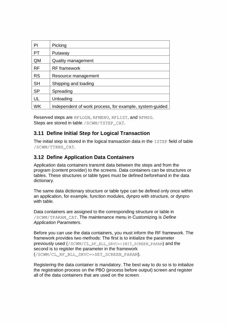
PI PickingPT PutawayQM Quality managementRF RF frameworkRS Resource managementSH Shipping and loadingSP SpreadingUL UnloadingWK Independent of work process, for example, system-guided
Reserved steps are RFLOGN, RFMENU, RFLIST, and RFMSG.Steps are stored in table /SCWM/TSTEP_CAT.
3.11 Define Initial Step for Logical TransactionThe initial step is stored in the logical transaction data in the ISTEP field of table/SCWM/TTRNS_CAT.
3.12 Define Application Data ContainersApplication data containers transmit data between the steps and from theprogram (content provider) to the screens. Data containers can be structures ortables. These structures or table types must be defined beforehand in the datadictionary.
The same data dictionary structure or table type can be defined only once withinan application, for example, function modules, dynpro with structure, or dynprowith table.
Data containers are assigned to the corresponding structure or table in/SCWM/TPARAM_CAT. The maintenance menu in Customizing is DefineApplication Parameters.
Before you can use the data containers, you must inform the RF framework. Theframework provides two methods: The first is to initialize the parameterpreviously used (/SCWM/CL_RF_BLL_SRVC=>INIT_SCREEN_PARAM) and thesecond is to register the parameter in the framework(/SCWM/CL_RF_BLL_SRVC=>SET_SCREEN_PARAM).
Registering the data container is mandatory. The best way to do so is to initializethe registration process on the PBO (process before output) screen and registerall of the data containers that are used on the screen.

From a visual perspective, the RF framework acts as a library. Structures andtables defined in Customizing represent the books, and the data is stored withineach of these books. In other words, the framework contains several types ofdata in “books”. When the system displays a screen, the framework (library)provides only those structures and tables (books) that are required by the screen(reader). Even if the framework contains multiple data containers, only those thatare actually needed are transferred to the screen or function module.
Example:The framework contains several data containers: CS_ADMIN, CS_PTWY,CS_UNLO, CS_PACK, and so on.
The screen displays putaway data from CS_PTWY only. In this case, theframework transfers CS_PTWY to the screen and so the values of CS_PTWY aredisplayed on the screen.
If CS_PTWY is not defined as a data container or CS_PTWY is not registered as ascreen parameter, there is no data to transfer and so the screen will containempty data.
3.12.1 Using Tables in the RF FrameworkFunction modules can use any number of tables. Each screen can presentmultiple structures but only one table. The content provider must specify whichtable will be presented by using method/SCWM/CL_RF_BLL_SRVC=>SET_SCR_TABNAME. The content provider mustalso specify which line of the table will be presented by using method/SCWM/CL_RF_BLL_SRVC=>SET_LINE.
3.13 Create Template ScreenThe template screen contains pushbuttons and encompasses the subscreen.It is an object that belongs to the RF framework, whereas the subscreens belongto the content provider.
We provide a standard 8x40 template in program /SCWM/SAPLRF_TMPL withscreen 0001 for pushbutton handling and screen 0002 for message handling.
3.13.1 Use Custom Template DynproIf you want to make changes at template level, for example, placing apushbutton, changing the number of pushbuttons, or changing the size of thesubscreen, you must define your own template screen.
If you want to display an error message on the bottom line, the field must refer to/SCWM/S_RF_SCRELM-MSGTX.

3.14 Create SubscreensSubscreens belong to the content provider and should be developed in package/SCWM/CORE_RF_EN or /SCWM/CORE_RF_DE. The subscreens must be storedin a function group. The naming convention for the function group is/SCWM/RF_<Process> (for example, /SCWM/RF_PUTAWAY or/SCWM/RF_PICKING).
The flow logic (PBO and PAI) of the subscreen must be simple. Furthermore, thetwo modules STATUS_SSCR in PBO and USER_COMMAND_SSCR in PAI (processafter input) are standard modules that must be included in the subscreen. Werecommend that you do not add your own modules to the subscreen flow logic.All processing should be done in the function modules defined in step flow table/SCWM/TSTEP_FLOW. These two modules are also automatically added whenyou use the Screen Management Tool to change your standard screens.
The modules are part of include /SCWM/IRF_SSCR. You must include this in thefunction pool of your function group.
The flow logic of a subscreen should appear as follows:
PROCESS BEFORE OUTPUT.* Common routine to control screen objects
* before the dynpro is displayed.* The module exists in include /SCWM/LRF_SSCRO01 MODULE STATUS_SSCR.
*PROCESS AFTER INPUT.* Common routine to handle standard function codes* The module exists in include /SCWM/LRF_SSCRI01
MODULE USER_COMMAND_SSCR.
The flow logic of a subscreen with a step-loop should appear as follows:PROCESS BEFORE OUTPUT.* pass structures to the screen
* set screen attributes MODULE status_sscr_loop.* pass table rows to the step-loop
LOOP. MODULE loop_output. ENDLOOP.* set (disable/enable) PGUP/PGDN pushbuttons on the screen
MODULE loop_scrolling_set.*PROCESS AFTER INPUT.
LOOP.

* save data of the step-loop elements MODULE loop_input.
ENDLOOP.
* pass input to the application, return function code* to the program
MODULE user_command_sscr.
All screen objects must be taken from the assigned structure of the appropriatedata container. The screen objects must not have the same name as thecontainer. You must use the structure of the table line for tables.
In the function pool definition you should add the include /SCWM/IRF_SSCR,which contains the required subroutines and data definition.
Defining a pushbutton on the subscreen is strictly forbidden because this couldimpact the ITS environment. Instead, use the pushbutton from the templatescreen (see Section 3.3.1).
3.14.1 Predefined Screen GroupsScreen groups 1 and 3 must only be used as described below. Your own codingshould only use screen group 4.
3.14.1.1 Group 1
001 Blocked for internal use to support required input fields. DO NOT USE thisscreen group. Group1 is filled / overwritten at runtime.
3.14.1.2 Group 3
001 Hide empty fields. If a verification field is assigned to a suppressed datafield, the verification field will also be suppressed automatically withoutusing screen groups.
002 For verification fields only. Disable field after successful verification. Thisalso marks the field as a verification field.
3.14.2 Automatic Page Up / Page Down ImplementationDefine a table type in the data dictionary.
Assign the table type to a parameter in table /SCWM/TPARAM_CAT.
Use this table type in your function module in which you read the data and fillyour parameter. Note that you must always define this in the CHANGINGparameter.

Once you have filled the parameter data in your function module, call methodSET_SCR_TABNAME from class /SCWM/CL_RF_BLL_SRVC to register the tablename in the RF framework and call method SET_LINE from class/SCWM/CL_RF_BLL_SRVC to register the first displayed line.
Note that the table name to be registered is the table type and not the parametername.
Note also that the screen fields must named in the same way as the line type ofyour table type in the dynpro.
The pushbuttons on the dynpro must refer to /SCWM/S_RF_SCRELM-PGUP and/SCWM/S_RF_SCRELM-PGDN. We recommend that you implement thepushbuttons with a length of 3 characters. The pushbuttons must be defined withthe function codes PGUP and PGDN.
The pushbuttons are controlled by the RF framework.
* Transfer table name into RF framework CALL METHOD /scwm/cl_rf_bll_srvc=>set_scr_tabname EXPORTING iv_scr_tabname = '/SCWM/TT_RF_PROTO_TAB' .
* Set displaying line number of table CALL METHOD /scwm/cl_rf_bll_srvc=>set_line EXPORTING iv_line = 1 .
You can use Page Up / Page Down to control either a screen or a step-loop ona screen. In the first case, your table contains multiple entries and only one entryis displayed on the screen at a time. With Page Down, the next entry in the tableis displayed. In the second case, your screen contains a step-loop and you onlycontrol the behavior of the step-loop.
3.14.3 Field to Field Navigation
3.14.3.1 Navigation Between Verification FieldsThe cursor is always positioned in the first field that is ready for input. When afield is verified successfully, it is deactivated and the cursor is moved to the nextfield that is ready for input.The content provider is not called during navigation.For more information, see Verification.
3.14.3.2 Navigation Between Input Fields (No Verification Fields)In contrast to the verification fields, normal input fields are not deactivated oncedata has been entered. As a result, navigation behavior differs.

The cursor is positioned in the first field that is ready for input. The current field isan attribute of the service class of the business logic layer(/SCWM/CL_RF_BLL_SRVC). This class also provides two methods to get(GET_FIELD) and set (SET_FIELD) the current field. Navigation within thescreen can be influenced using these.
In the standard SAP system, the cursor is positioned in the next initial input field.Pay attention to any input fields that could contain a valid initial value. Forexample, an indicator with appropriate values of blank and X. In this case, youmust mark all fields that have to be entered in the field attribute in the dynpro asInput obligatory.
You can also move the cursor manually using the TAB key or the arrow keys.The content provider is not called during navigation. The content provider is onlycalled once all of the fields have been filled. If you want to process an error andposition the cursor in a certain field, use method/SCWM/CL_RF_BLL_SRVC=>SET_FIELD for positioning.
3.14.3.3 Navigation on a Screen with Input Fields and Verification FieldsIn this case, the navigation behavior processes the verification fields first andthen the input fields.
3.14.4 Exiting a Screen Without Saving Data in Internal StructuresIf your screen contains input fields and you want to exit without saving the data inthe internally used structures as defined in table /SCWM/TPARAM_CAT, you mustdo so by choosing Back. Otherwise, your data will be rendered inconsistent if youuse the same data structures.
To enable this, assign the function code BACK in table /SCWM/TFCOD_PRF to afunction key, pushbutton, or shortcut. In the step flow (table/SCWM/TSTEP_FLOW), an entry is not necessary because the content provider isnot called.
3.14.5 Exiting a Screen and Saving Data in Internal StructuresIn contrast to the BACK function code, UPDBCK updates the data on the stack andthe screen called can use the updated data. With UPDBCK, the content providernot called.
3.14.6 Exiting a Screen and Calling the Content ProviderIn some cases, you have to call the content provider before you exit a screen. Inthis case, you cannot use BACK or UPDBCK directly. Assign another function code(such as BACKF) to your function key, pushbutton, or shortcut but use the keythat is normally used for BACK (F7). With the new function code, the contentprovider is called and you can then set the BACK function code, which isprocessed by the framework. In this case, your step flow would be:

APPLIC PRES_PRF LTRANS STEP FCODE FMODUL SSTEP PRMOD FCODE_BCKG
01 **** LTX1 STEP2 BACKF FM1 STEP2 1 BACKNote that PRMOD must be 1, SSTEP = STEP, and FCODE_BCKG must be BACK.
3.15 Define Function Code CatalogDefine the required function codes of the pushbuttons and function keys used inbackground step processing. To do so, choose the Customizing activity DefineSteps in Logical Transactions and choose Define Function Codes. Do not definethe function codes directly in the database table.The function codes are defined in table /SCWM/TFCOD_CAT.
3.15.1 Predefined Function Codes in the RF FrameworkCurrently, there are several predefined function codes for decreasing applicationdevelopment effort. Function codes mean logical codes used in the step flow,and not simply the function codes triggered by pushbuttons or function keys.FunctionCode
Description of the Function Triggered
INIT Starts the logical transaction; if an entry for the initial step andfunction code INIT is defined in table /SCWM/TSTEP_FLOW,this entry is the PBO for the first dynpro. If no entry is defined,the initial step is displayed in the foreground.
CLEAR Clears the input field that currently contains the cursor. If youchoose CLEAR twice without changing the position of the cursor,the system clears all of the input fields. This behavior can becustomized in field FLG_CLEAR_ALL of table/SCWM/TPRDV_CAT. In the standard SAP system, this feature isactivated. With CLEAR, the flow logic does not return from thescreen. This means that CLEAR does not trigger a step flow.
BACK Navigates flow logic to the previous foreground step. If you havedefined PBO steps in table /SCWM/TSTEP_FLOW, however(such as the INIT step), the PBO steps are NOT reprocessed.
ENTERLIST Displays a screen containing a list of possible entries for the
current input field. Corresponds to a list-box display.UPDBCK Updates the data in the stack and returns to the previous
foreground step. If you need to perform steps in addition to themain operation step, for example, exception handling todetermine a new storage bin, the main operation data changes.If you leave the exception with UPDBCK, the system updates thestack data.

NEXTSC Used when a screen is split. The next screen of the split screencan be accessed using this function code.
BUILD_MENU Used in standard service step MENUPGUP Used for automatic page up implementationPGDN Used for automatic page down implementationYES Used in standard service step MESSAGE / QUERYNO Used in standard service step MESSAGE / QUERYMORE Used for navigation with grouped pushbuttons. The next
pushbutton group is displayed using MORE. If you apply this tothe last group, the system switches to the first group.
FULLMS Displays error messages on a separate screen. Used to viewthe full text of an error message if the bottom line is notsufficient.
UNKNOW Used internally to handle unmapped function codes from thescreen that are not defined in table /SCWM/TSTEP_FLOW.
UPDPST Light synchronous postingCLSEMS Clears message lines and displays the screen as standardCMPTRS Ends a logical transaction. This function code must be set at the
end of each logical transaction using the SET_FCODE method ofclass /SCWM/CL_RF_BLL_SRVC to continue in the defined way.
3.16 Assign Text to Function CodeYou assign text to function codes in table /SCWM/TOBJ_TXT. The length of thefunction code text is defined in the display profile.
3.17 Create Services to Support Business LogicA service is a function module that is assigned to a step flow definition. Thefunction modules include the coding that is normally specified in the PBO andPAI modules.
The function module interface is restricted. Only CHANGING parameters areallowed. The parameters can contain structures and tables. Field parameters arenot allowed.
Note: The function module of the last step of the logical transaction must callmethod SET_FCODE of class /SCWM/CL_RF_BLL_SRVC. Function code CMPTRSmust be set with this function. Alternatively, you can set or process this functioncode in step flow /SCWM/TSTEP_FLOW in background mode.
* Call method of RF framework to mark end of transaction

/scwm/cl_rf_bll_srvc=>set_prmod('1').
/scwm/cl_rf_bll_srvc=>set_fcode( /scwm/cl_rf_bll_srvc=>c_fcode_compl_ltrans ).
3.18 Define State CatalogueStates identify relatively small differences in the same step behavior andpresentation view. You must take into account that the state is a parameter of thestep and you can load it with its own features. You can omit or add somefunctions (such as pushbuttons and functions keys) in accordance with the stateand verification profile, and define a specific screen for a particular state of thestep.
We recommend that you change the behavior of the step in accordance withparameters with a state definition instead of doing so with a new step.
The state used is controlled by the content provider. Depending on your ownrules, you set the state with method /SCWM/CL_RF_BLL_SRVC=>SET_STATE.The state is used in tables /SCWM/TFCOD_PRF, /SCWM/TSTEP_SCR, and/SCWM/TVALID_PRF. You can define new states in the Customizing activityDefine Steps in Logical Transactions by choosing Define Steps Define States.A state can only be defined for a step.
The framework uses the following predefined states internally:· FIRST to show the first page of menu items.· MIDDLE to show inner pages of menu items.· LAST to show the last page of menu items.· QUERY· INFERR
Example: The system can display the logon screen for the user in three differentstates: after disconnection with attached worklist; after disconnection withoutattached worklist; and after normal logoff. The same step is used for all threestates, defining specific function codes for each state: DISCONNECT,RECONNECT, or CONNECT.
3.19 Map Logical Transaction Step to SubscreenEach step processed in the foreground must have a corresponding subscreenand program.
You configure this in the Customizing activity Define Steps in LogicalTransactions by choosing Define Logical Transactions Map LogicalTransaction Step to Sub-Screen.
Mapping data is stored in table /SCWM/TSTEP_SCR.

3.20 Define Function Code ProfileIn the function code profile, you define the pushbutton and function key for thescreen or step. You can also define an external reason code and disable thefunction code, pushbutton, or function key.
The pushbuttons are assigned to the template at runtime.
If you want to only activate the function key and not display the pushbutton, leavethe PUSHB field empty.
If you want to activate only the pushbutton and not a corresponding function key,leave the FNKEY field empty.
The text on the pushbutton can be maintained in the Customizing settings for RFin which the function codes are defined (if used).
If you want to use standard function codes such as BACK or CLEAR, you mustdefine them in the function code profile. They are not automatically available.Be careful if you use additional states in your logical transaction. State ****** isused as the default. This means that function codes that are not defined in youradditional state are automatically added by the framework. If you want to avoidthis, you can copy the entries with state ******* and select field FLG_DISABLE. Ifyou always work with custom states and not with state ******, you can delete theentries with state ******.
Be aware that F10 cannot be used directly. This function key cannot beaddressed directly in the GUI status. If you require F10 on the device, aworkaround is available. Pressing F10 on the device triggers an esc-sequenceof, for example, SHIFT+F10. SHIFT+F10 is used in the function code profile anddefined in the GUI status. Note, however, that this solution does not work in theSAPGUI.
The following function codes should be used in the standard SAP system andassigned to the following function keys:FunctionCode
FunctionKey
Shortcut Action
NEXT F4 04 Jump to next screen (for example, fromsource to destination or from destination toend of transaction)
MORE F5 05 Display next pushbutton sequenceCLEAR F6 06 Clear input field / Clear all input fieldsBACK F7 Returns to previous screen without saving
entered data in data container

UPDBCK F7 Returns to previous screen and savesentered data in data container
LIST F8 08 Display possible data for the current fieldFULLMS F9 09 Display message on separate screenENT ENTER Default navigation
If you display pushbuttons, only the non-standard functions are displayed (suchas the detail screen). No pushbuttons should be assigned to the function codesmentioned above except for NEXT (which is controlled by the content provider).The function code profiles are stored in table /SCWM/TFCOD_PRF.
3.20.1 GUI Status Is Defined for the TemplateThe GUI status is defined at template level and is, therefore, valid for allsubscreens.
The pushbuttons and function keys are dynamically excluded in accordance withthe definition in /SCWM/TFCOD_PRF. This means that in the GUI status, allnecessary function keys must be defined in advance.
All function keys must be defined as Application function for functional type. Donot define them as Exit Command. Exit Command function keys are not currentlysupported.
3.20.2 Connect Screen Function Codes and RF Framework FunctionCodes
In the GUI status, the function keys are defined with the function codes. Youhave F1 to F10 for the corresponding function keys, ENT for ENTER, PGUP forPAGE UP and PGDN for PAGE DOWN. No pushbuttons are defined in the GUIstatus.
On the template dynpro, the pushbuttons are defined with the function codes PB1to PB4.
The function codes used in the step flow are defined in table/SCWM/TFCOD_CAT. Here you define more meaningful function codes such asBACK, ENTER, DETAIL, SAVE, and so on.
In table /SCWM/TFCOD_PRF, you establish the link between the GUI functioncodes and the RF framework function codes and step flow.
APPLIC LTRANS STEP STATE SQNCE FCODE PUSHB FNKEY Shortcut
01 LTX1 STEP1 ****** 01 DETAIL PB1 F1 01

01 LTX1 STEP1 ****** 01 CLEAR F6 0601 LTX1 STEP1 ****** 01 BACK F7 0701 LTX1 STEP1 ****** 01 FULLMS F9 0901 LTX1 STEP1 ****** 01 ENTER ENT01 LTX1 STEP2 ****** 01 SPLIT PB1 F1 0101 LTX1 STEP2 ****** 01 ZERO PB2 F2 0201 LTX1 STEP2 ****** 01 NEST PB3 F3 0301 LTX1 STEP2 ****** 01 CLEAR F6 0601 LTX1 STEP2 ****** 01 BACK F7 0701 LTX1 STEP2 ****** 01 FULLMS F9 0901 LTX1 STEP2 ****** 01 ENTER ENT
Note that some columns are not displayed to provide a better overviewBy defining the above table, you specify that in STEP1, only the first pushbutton(PB1 in the left-hand corner) is valid and visible with the function code DETAIL.In addition, the function codes CLEAR, BACK, and FULLMS are assigned tofunction keys and a shortcut value. The function code ENTER is assigned to theENTER key without a shortcut value. In STEP2, you have the three pushbuttonson the top, valid and visible, and assigned to the function keys F1 to F3. The restis the same as in STEP1.
3.20.3 Handle More Function Codes Than Available Pushbuttons on aScreen or Step
If you have more function codes than available pushbuttons on your screen or, inother words, on your step, you have the following option. In table/SCWM/TFCOD_PRF, group your function codes with field SQNCE. This field alsoindicates the sequence of the groups. In addition, each group must contain thefunction code MORE, which must be assigned to a function key. Do not assignMORE to a pushbutton. The RF framework will display a greater than symbol (>)automatically if more function codes than available pushbuttons are defined. Thesymbol indicates to the user that more function codes are available. The usermust know which function key triggers the MORE function code. The RFframework is responsible for presenting the correct group. After the last group,the first group is displayed again. Each function code to be processed must bedefined in each group.APPLIC LTRANS STEP STATE SQNCE FCODE PUSHB FNKEY Shortcut
01 LTX1 STEP3 ****** 01 DETAIL PB1 F1 0101 LTX1 STEP3 ****** 01 SPLIT PB2 F2 02

01 LTX1 STEP3 ****** 01 ZERO PB3 F3 0301 LTX1 STEP3 ****** 01 MORE F5 0501 LTX1 STEP3 ****** 01 CLEAR F6 0601 LTX1 STEP3 ****** 01 BACK F7 0701 LTX1 STEP3 ****** 01 FULLMS F8 0801 LTX1 STEP3 ****** 01 NEXT PB4 F4 0401 LTX1 STEP3 ****** 01 PRINT F11 11
01 LTX1 STEP3 ****** 02 PRINT PB1 F11 1101 LTX1 STEP3 ****** 02 NEXT F4 0401 LTX1 STEP3 ****** 02 MORE F5 0501 LTX1 STEP3 ****** 02 CLEAR F6 0601 LTX1 STEP3 ****** 02 BACK F7 0701 LTX1 STEP3 ****** 02 FULLMS F9 0901 LTX1 STEP3 ****** 02 DETAIL F1 0101 LTX1 STEP3 ****** 02 SPLIT F2 0201 LTX1 STEP3 ****** 02 ZERO F3 03
In this example, we have assumed a display profile with only four pushbuttons.We have defined two groups, and all groups have the same function codes.There are function codes with a pushbutton assignment and function codeswithout a pushbutton assignment in each group. Note that function codes notdefined in the actual sequence are not available and cannot be processed. Youmust define them without assigning a pushbutton.
3.21 Define Step FlowThe step flow determines the business process flow and the correspondingcontent provider function modules. Only function modules can be used. Althoughfunction modules can be combined in the standard SAP system, there shouldonly be one function module for the PBO (Process Before Output) and one forthe PAI (Process After Input). The naming convention is/SCWM/RF_<Process_<Step>_PBO or /SCWM/RF_Process_Step_PAI (forexample, /SCWM/RF_PTWY_SOURCE_PBO or /SCWM/RF_PICK_CHECK_PAI). Itis clear that within these function modules, you can call other function modulesthat can be reused. Having only one function module makes Customizing easierand also helps to follow the step flow.

In the step flow definition, you define the transaction step sequence taking intoaccount the function code applied by the user. Steps may be displayed in theforeground or processed in the background as determined in Customizing. Stepscan be combined. If you combine steps, the step flow is interrupted only by errormessages. Be careful with error messages issued from a function module that isprocessed before the screen is displayed (PBO). The message is displayed onthe next screen and not on the previous one. This means that the user canproceed without correcting the old error. The error should be checked again inthe PAI module.
The step flow is defined in table /SCWM/TSTEP_FLOW.PRMOD 1 -> Background processingPRMOD 2 -> Foreground display
3.21.1 PBO of Initial Screen After Menu SelectionThe table entry in PBO of the initial screen should appear as follows:
APPLIC PRES_PRF LTRANS STEP FCODE FMODUL SSTEP PRMOD FCODE_BCKG
01 **** LTX1 STEP1 INIT FM1_PBO STEP1 2
For logical transaction LTX1 in step STEP1, once the transaction has beentriggered from the menu function module, FM1_PBO is processed and the screenis displayed.
It is hardcoded that the function code for the first function module call must beINIT.
3.21.2 PAI of Screen and Direct Display of Next ScreenThe table entry in PAI should appear as follows:
APPLIC PRES_PRF LTRANS STEP FCODE FMODUL SSTEP PRMOD FCODE_BCKG
01 **** LTX1 STEP1 ENTER FM1_PAI STEP2 2
For logical transaction LTX1 in step STEP1, after the ENTER function code hasbeen triggered, function module FM1_PAI is processed and the new screenassigned to STEP2 is displayed.
3.21.3 PAI of Screen and PBO of Next ScreenIn PAI of screen 1 and PBO of screen 2, the table entry should appear as follows:
APPLIC PRES_PRF LTRANS STEP FCODE FMODUL SSTEP PRMOD FCODE_BCKG
01 **** LTX1 STEP1 ENTER FM1_PAI STEP2 1 BCK01

01 **** LTX1 STEP2 BCK01 FM2_PBO STEP2 2
For logical transaction LTX1, function module FM1_PAI is processed in stepSTEP1 after the ENTER function code has been triggered. FM2_PBO is thenprocessed in the background and the new screen from STEP2 is displayed.
3.21.4 Call of Common Screen from Several Screens During TransactionIf you want to call one screen from several steps of your logical transaction, youmust only ever leave the screen using the function code BACK or UPDBCK. Theinternal call stack is only updated correctly with BACK and UPDBCK. If you want toleave the screen with another function code for any reason, create an entry intable /SCWM/TSTEP_FLOW as described below.
Additionally, you define which step the verification is to carry out beforehand. Ifyou have more steps, only set the Verification indicator once.
Example: WT detail screen called from source screen and destination screen.
APPLIC PRES_PRF LTRANS STEP FCODE FMODUL SSTEP PRMOD FCODE_BCKG
01 **** LTX1 STEP1 ENTER STEP1 1 BACK
With this definition, the detail screen is left with ENTER and function code BACK isprocessed in the background.
3.21.5 Customizable ENTER / Set Next Step Dynamically Using the CPIt should be possible that the CR (Carriage Return) received from a scanner orthe user by pressing ENTER is redefined to act like a combination of severalfunction keys, for example, F1 (SAVE) and F4 (NEXT).ENTER should respond as follows:
· If you are not in the last input field, the cursor is positioned in the nextinput field (either verification or input field).
· If you are in the last input field but not on the last open WT, the actual WTis saved and the next open WT is displayed (source or destination).
· If you are in the last input field and on the last open WT, the actual WT issaved and comes from the source screen. The destination screen of thefirst TO is displayed. The transaction is finished when the last open WT isclosed and confirmed by the destination screen.
Example: The ENTER key is defined as function code ENTER. The ENTER keytriggers navigation between the input fields and posting to the database. If allfields are entered, the step flow is divided into three steps: navigation, check ofthe data entered, and posting to the database.

APPLIC PRES_PRF LTRANS STEP FCODE FMODUL SSTEP PRMOD FCODE_BCKG
01 **** LTX1 STEP1 ENTER FM_NAV STEP1
01 **** LTX1 STEP1 SOURCE STEP2 2
01 **** LTX1 STEP1 DEST STEP3 2
It is important that the processing mode (PRMOD) and the background functioncode (FCODE_BCKG) are initial.These fields are filled in function module FM_NAV with the following two methods:
· /SCWM/CL_RF_BLL_SRVC=>SET_PRMOD· /SCWM/CL_RF_BLL_SRVC=>SET_FCODE
Example coding for the navigation function module:
* If only assigned ones were found, we must jump to destination
IF lv_enqueue IS INITIAL.
/scwm/cl_rf_bll_srvc=>set_prmod('1').
/scwm/cl_rf_bll_srvc=>set_fcode('DEST').
EXIT.
ELSE.
* We found un-assigned ones and are continuing with source
/scwm/cl_rf_bll_srvc=>set_prmod('1').
/scwm/cl_rf_bll_srvc=>set_fcode('SOURCE').
ENDIF.
3.21.6 Additional InformationAll actions that can be counted as PBO of STEP2 in connection STEP1 STEP2must be attached to initial code of STEP2. Otherwise they will be attached toSTEP1. BACK to STEP1 will recover STEP1 with all changes not relevant toSTEP1.
Example:
APPLIC LTRANS STEP FCODE FMODUL SSTEP PRMOD FCODE_BCKG
01 LTX1 STEP1 FCODE_X MODULE_X STEP2 1 INIT_2
01 LTX1 STEP2 INIT_2 MODULE_INIT_2 STEP2 2
MODULE_X: actions associated with STEP1 because the module is called beforethe next foreground step is processed. If STEP2 works with another table andyou set the new table name too early (for example, in MODULE_X), this change
is stored in the data for STEP1. When you return from STEP2, the data isrestored and STEP1 works on the wrong table.
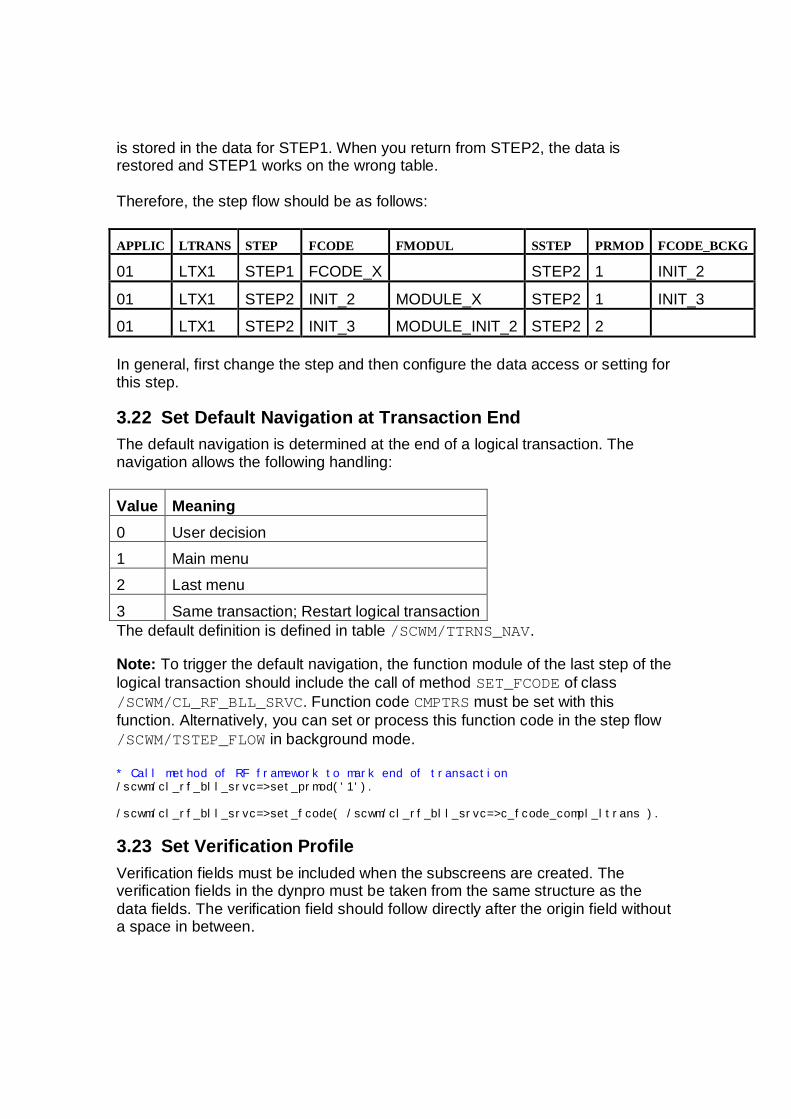
Therefore, the step flow should be as follows:
APPLIC LTRANS STEP FCODE FMODUL SSTEP PRMOD FCODE_BCKG
01 LTX1 STEP1 FCODE_X STEP2 1 INIT_2
01 LTX1 STEP2 INIT_2 MODULE_X STEP2 1 INIT_3
01 LTX1 STEP2 INIT_3 MODULE_INIT_2 STEP2 2
In general, first change the step and then configure the data access or setting forthis step.
3.22 Set Default Navigation at Transaction EndThe default navigation is determined at the end of a logical transaction. Thenavigation allows the following handling:
Value Meaning0 User decision1 Main menu2 Last menu3 Same transaction; Restart logical transactionThe default definition is defined in table /SCWM/TTRNS_NAV.
Note: To trigger the default navigation, the function module of the last step of thelogical transaction should include the call of method SET_FCODE of class/SCWM/CL_RF_BLL_SRVC. Function code CMPTRS must be set with thisfunction. Alternatively, you can set or process this function code in the step flow/SCWM/TSTEP_FLOW in background mode.
* Call method of RF framework to mark end of transaction/scwm/cl_rf_bll_srvc=>set_prmod('1').
/scwm/cl_rf_bll_srvc=>set_fcode( /scwm/cl_rf_bll_srvc=>c_fcode_compl_ltrans ).
3.23 Set Verification ProfileVerification fields must be included when the subscreens are created. Theverification fields in the dynpro must be taken from the same structure as thedata fields. The verification field should follow directly after the origin field withouta space in between.

In the verification profile, you assign the verification field to the comparing datafield including the data structure. The translation method for the barcode (forexample, to support EAN128 in EM function module/SCWM/RF_EAN128_SPLIT_VALID) is implemented and explicit disabling hasbeen defined here. If you do not need a one-to-one verification (for example, ifthe material can be identified by the material number and EAN/UPC number),you can define a function module that carries out the verification instead of theframework.
Be careful if you use additional states in your logical transaction. State ****** isused by default. This means that verification fields that are not defined in youradditional state are automatically added by the framework. If you want to avoidthis, you can copy the entries with state ******* and select field FLG_DISABLE. Ifyou always work with your own states and not with state ******, you can deletethe entries with state ******.
3.23.1 VerificationDefine the verification fields in your dynpro. The verification fields are alwayscharacter-based with a length of 50 characters. Screen group 3 for these fieldsmust be filled with 002. This activates the verification fields and enables the RFframework to deactivate the verification field after successful verification. If thescreen group does not contain 002, the fields will never be verified.
In table /SCWM/TVALID_PRF, assign the verification field to the field thatcontains the comparing data value.
APPLIC LTRANS STEP STATE VRFVAL_TABNAME
VRFINP_FLDNAME
VRFVAL_FLDNAME
01 LTX1 STEP1 ****** /SCWM/S_RF_PROTO
NLPLA_VERIF NLPLA
01 LTX1 STEP1 ****** /SCWM/S_RF_PROTO
CHARG_VERIF CHARG
Be aware that some columns are not displayed in order to improve the overview.
In the table definition above, you have defined that in STEP1, you have twoverification fields named /SCWM/S_RF_PROTO-NLPLA_VERIF and/SCWM/S_RF_PROTO-CHARG_VERIF. The data of the first verification field ischecked against the data in field /SCWM/S_RF_PROTO-NLPLA and the second ischecked against /SCWM/S_RF_PROTO-CHARG.
In field FLG_VERIF of table /SCWM/TSTEP_FLOW, you define the step beforewhich verification is to be carried out. Note that verification must only be carried

out once. If you have more than one step, only one step (normally the first)should be indicated as Verification relevant.
Verification is carried out automatically in the RF framework in method/SCWM/CL_RF_BLL_SRVC=>CHECK_VERIF_PRF. The field with the comparingdata value must be in a structure defined in table /SCWM/TPARAM_CAT.
If you add a function module, verification control is based on the content providerand the check must be carried out in the function module. As an IMPORTparameter, the function module must have a structure named IS_VERIF_PRF oftype /SCWM/S_VERIF_PRF_EXT and a field named IV_FLG_VERIFIED of typeXFELD. As an EXPORT parameter, a field must be created with the nameEV_FLG_VERIFIED and type XFELD. Optionally, you can have CHANGINGparameters in the same way as the other function modules that belong to thecontent provider. /SCWM/S_VERIF_PRF_EXT contains all information of thecurrent verification field from table /SCWM/TVALID_PRF and the conversion exitfor this field. IV_FLG_VERIFIED is selected if the framework already carried outa positive verification before the function module was called. EV_FLG_VERIFIEDcontains the return value. X indicates a positive verification and an initial valueindicates a negative verification. Note that the function module itself does nottrigger an error message. The standard error message is triggered by theframework.
If verification is not successful, error message /SCWM/UI_RF:020 (Invalidverification of &1) is processed. If the verification fields are empty, error message/SCWM/UI_RF:021 (Enter verification of &1) is processed.
In field FLG_VERIF of table /SCWM/TSTEP_FLOW, you can specify thatverification is carried out before the next step or function module is processed. Ifnone of your steps or substeps contain the verification indicator, no verification iscarried out.
Note that the verification fields must be longer if you verify using barcodescanning and you use concatenated barcodes such as EAN128. Otherwise, thescanned barcode information may be truncated because of the limitation to theinput field length.
In the RF framework application table (/SCWM/TAPPL_CAT), you can define afunction module to influence or control the verification fields based on the actualapplication data. For example, if you pick from storage type 0001, you want toverify fields other than by picking from storage type 0002. The RF transactionopens all verification fields by default. You can use the function module todeactivate verification fields. The example function module is/SCWM/RF_WME_SET_VERIFICATION.

3.24 Presentation Device CatalogIn the catalog, you define the single RF device and its characteristics such as thedisplay profile, presentation device type, data entry type, and function keyquantity. You also define indicators for the CLEAR ALL function, enablingshortcuts to the templates, and the default device, as well as the sounds that areissued when a warning message or success message appears. The devicecatalog is stored in table /SCWM/TPRDV_CAT.

4 LayoutThe following information is a general proposal for the screen layout and isintended to help developers to design the screens. This information does notaddress all of the open issues. If you have additional information that may be ofinterest to other developers, contact the author and request that the document beupdated.
4.1 ScreenThe screen size for the subscreen is 7x40. Make sure that you use this space. Itis easier for customers to delete a field than to add one, and so it is advisable tocreate a random field if additional space is available.
The fields should start at line 1, column 1.
The fields on the screen should be arranged line by line. This means that emptylines should be omitted (not implemented).
4.2 FieldsThe RF screens use different (shorter) field labels than the normal UIs. We havetherefore created data elements for RF based on the domains from standarddata elements.
Use the 10-character field label if possible.
If no suitable field is available, use the following procedure to obtain one:1. Create your own data element using the naming convention
/SCWM/DE_RF_xxxxxxx and domain according to the data element.2. Define the field labels with a length of 4, 6, 8, and 10 characters. For the
field lable with 10 characters, search for a standard term in SAPterm (inthe Corporate Portal, use the quick link /sapterm). If you find abbreviationsin SAPterm that can be entered in the field sizes, use the standardabbreviation. If there is no abbreviation, you must create your own.
3. Add the new data element to structure /SCWM/S_RF_SCRTXT.4. Add the new data element to your own structure.5. Use the field of your structure on your screen.
Not all of the fields have a field label. For example, Storage bin contains thefields Storage type and Storage bin.
Field attributes are set directly in the dynpro. You can use screen group 003 withvalues 001 and 002. The framework still offers methods of changing fieldattributes at runtime. These methods can be called in your function module thatis processed before the screen is displayed. You can activate or deactivate the
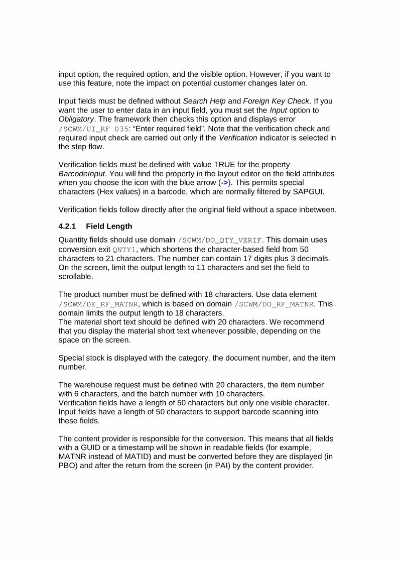
input option, the required option, and the visible option. However, if you want touse this feature, note the impact on potential customer changes later on.
Input fields must be defined without Search Help and Foreign Key Check. If youwant the user to enter data in an input field, you must set the Input option toObligatory. The framework then checks this option and displays error/SCWM/UI_RF 035: “Enter required field”. Note that the verification check andrequired input check are carried out only if the Verification indicator is selected inthe step flow.
Verification fields must be defined with value TRUE for the propertyBarcodeInput. You will find the property in the layout editor on the field attributeswhen you choose the icon with the blue arrow (->). This permits specialcharacters (Hex values) in a barcode, which are normally filtered by SAPGUI.
Verification fields follow directly after the original field without a space inbetween.
4.2.1 Field LengthQuantity fields should use domain /SCWM/DO_QTY_VERIF. This domain usesconversion exit QNTY1, which shortens the character-based field from 50characters to 21 characters. The number can contain 17 digits plus 3 decimals.On the screen, limit the output length to 11 characters and set the field toscrollable.
The product number must be defined with 18 characters. Use data element/SCWM/DE_RF_MATNR, which is based on domain /SCWM/DO_RF_MATNR. Thisdomain limits the output length to 18 characters.The material short text should be defined with 20 characters. We recommendthat you display the material short text whenever possible, depending on thespace on the screen.
Special stock is displayed with the category, the document number, and the itemnumber.
The warehouse request must be defined with 20 characters, the item numberwith 6 characters, and the batch number with 10 characters.Verification fields have a length of 50 characters but only one visible character.Input fields have a length of 50 characters to support barcode scanning intothese fields.
The content provider is responsible for the conversion. This means that all fieldswith a GUID or a timestamp will be shown in readable fields (for example,MATNR instead of MATID) and must be converted before they are displayed (inPBO) and after the return from the screen (in PAI) by the content provider.

5 Programming Information
5.1 PostingData for the RF transaction must be posted occur online. This allows the user toreact to any errors that may occur during posting. We recommend that data isposted in UPDATE TASK but the commit should be carried out by COMMIT WORKAND WAIT. Although errors may occur, this process ensures that the order withinthe posting is not changed.
5.2 Exception Handling and Using ShortcutsThe SHORTCUT field from structure /SCWM/S_RF_SCRELM is part of thetemplate. The field is four characters long, although only two of these charactersare displayed. You can use the field for navigation purposes by entering ashortcut value, and you can also use it to trigger exceptions by entering anexception code. You can define the field as optional or mandatory using theFLG_SHORTCUT indicator in table /SCWM/TPRDV_CAT. If you define the field asoptional, it is not considered in the default navigation. This means that choosingENTER on the last input field of the subscreen triggers the step flow. You mustnavigate to the field (for example, to enter an exception) manually using the TABkey. If you define the indicator as mandatory, the cursor is always set to the fieldonce the last input field on the subscreen has been completed. The user mustthen press ENTER again to trigger the step flow.
5.2.1 NavigationIn the FLG_SHORTCUT field of table /SCWM/TPRDV_CAT, you can controlwhether the shortcut function is activated. If the indicator is selected (mandatory),navigation is triggered when the user presses ENTER in the shortcut field. If theindicator is not selected, navigation is triggered when the user presses ENTER onthe last field of the screen. Reaching the shortcut field, which is the very last field,is not necessary. You must then navigate using the function keys.
Furthermore, to mark the flag you must assign the corresponding shortcut valuesin table /SCWM/TFCOD_PRF to the function codes that are to be triggered.Figures 1 to 10 are reserved for navigation. The figures reflect the function keysF1 to F10. Use the following assignment in the standard SAP system:
FCODE Function key ShortcutMORE F5 05CLEAR F6 06BACK or UPDBCK F7LIST F8 08
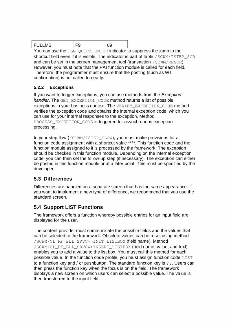
FULLMS F9 09You can use the FLG_QUICK_ENTER indicator to suppress the jump to theshortcut field even if it is visible. The indicator is part of table /SCWM/TSTEP_SCRand can be set in the screen management tool (transaction /SCWM/RFSCR).However, you must note that the PAI function module is called for each field.Therefore, the programmer must ensure that the posting (such as WTconfirmation) is not called too early.
5.2.2 ExceptionsIf you want to trigger exceptions, you can use methods from the Exceptionhandler. The GET_EXCEPTION_CODE method returns a list of possibleexceptions in your business context. The VERIFY_EXCEPTION_CODE methodverifies the exception code and obtains the internal exception code, which youcan use for your internal responses to the exception. MethodPROCESS_EXCEPTION_CODE is triggered for asynchronous exceptionprocessing.
In your step flow (/SCWM/TSTEP_FLOW), you must make provisions for afunction code assignment with a shortcut value ****. This function code and thefunction module assigned to it is processed by the framework. The exceptionshould be checked in this function module. Depending on the internal exceptioncode, you can then set the follow-up step (if necessary). The exception can eitherbe posted in this function module or at a later point. This must be specified by thedeveloper.
5.3 DifferencesDifferences are handled on a separate screen that has the same appearance. Ifyou want to implement a new type of difference, we recommend that you use thestandard screen.
5.4 Support LIST FunctionsThe framework offers a function whereby possible entries for an input field aredisplayed for the user.
The content provider must communicate the possible fields and the values thatcan be selected to the framework. Obsolete values can be reset using method/SCWM/CL_RF_BLL_SRVC=>INIT_LISTBOX (field name). Method/SCWM/CL_RF_BLL_SRVC=>INSERT_LISTBOX (field name, value, and text)enables you to add a value to the list box. You must call this method for eachpossible value. In the function code profile, you must assign function code LISTto a function key and / or pushbutton. The standard function key is F8. Users canthen press the function key when the focus is on the field. The frameworkdisplays a new screen on which users can select a possible value. The value isthen transferred to the input field.

5.5 Display of Text (from Delivery or Hazardous Material)A standardized method of retrieving and displaying text from the hazardousmaterial master and delivery is available. Function module/SCWM/RF_TEXT_GET_AND_SET reads the texts and transfers them to the RFframework (using method /SCWM/CL_RF_BLL_SRVC=>SET_RF_TEXT).You can then display the text by pressing F9 (function code FULLMS). The RFframework displays the text in a step-loop. If an error message is to be displayed,first the error message is displayed and then the text is displayed (from the errortext screen) when you press F9 again. An indicator is also displayed on theapplication screen to inform the user that text is available.
5.6 Methods Available to the Content Provider
5.6.1 Methods into the Framework· /scwm/cl_rf_bll_srvc=>set_prmod( '1' ) to set the processing
mode of the next step in the step flow. ‘1’ = Background; ‘2’ = Foreground
· /scwm/cl_rf_bll_srvc=>set_fcode( 'DEST' ) to set the functioncode to determine the next step flow
· /scwm/cl_rf_bll_srvc=>set_state( '******' ) to set the state
· /scwm/cl_rf_bll_srvc=>set_field( 'WHO' ) to set the cursor toa specific field
· /scwm/cl_rf_bll_srvc=>init_screen_param( ) to reset the datacontainer used. Resets only the name, not the data itself
· /scwm/cl_rf_bll_srvc=>set_screen_param( ‘PICKPT’ ) tointroduce the data container used
· /scwm/cl_rf_bll_srvc=>set_scr_tabname( 'TT_PICKPT' ) tointroduce the table data container used
· /scwm/cl_rf_bll_srvc=>set_line( 1 ) to set the actual /beginning line in the table data container used
· /scwm/cl_rf_bll_srvc=>init_listbox(‘/SCWM/S_RF_PICKPT-HUENT’ ) to reset the data assigned to thegiven listbox
· /scwm/cl_rf_bll_srvc=>insert_listbox(‘/SCWM/S_RF_PICKPT-HUENT’, ‘X’, ‘HU-Entnahme’ ) to set avalue for the given listbox. For additional data, call the method again.
· /scwm/cl_rf_bll_srvc=>set_screlm_required_on(‘/SCWM/S_RF_PICKPT-VLPLA’) to activate the required field attribute for the givenfield

· /scwm/cl_rf_bll_srvc=>set_screlm_required_off(‘/SCWM/S_RF_PICKPT-VLPLA’) to deactivate the required field attribute for thegiven field
· /scwm/cl_rf_bll_srvc=>set_screlm_invisible_on(‘/SCWM/S_RF_PICKPT-VLPLA’) to activate the hidden field attribute for the givenfield
· /scwm/cl_rf_bll_srvc=>set_screlm_invisible_off(‘/SCWM/S_RF_PICKPT-VLPLA’) to deactivate the hidden field attribute for thegiven field
· /scwm/cl_rf_bll_srvc=>set_screlm_input_on(‘/SCWM/S_RF_PICKPT-VLPLA’) to activate the input field attribute for the given field
· /scwm/cl_rf_bll_srvc=>set_screlm_input_off(‘/SCWM/S_RF_PICKPT-VLPLA’) to deactivate the input field attribute for the given field
· /scwm/cl_rf_bll_srvc=>set_flg_stack(‘X’) to set a new stacklevel. This can be used if you want the framework to add a new stack levelto its internal stack.
· /scwm/cl_rf_bll_srvc=>message( ‘ ‘, ‘/SCWM/UI_RF, ‘S’,‘xxx’ ) to display a message of type S or I.
· /scwm/cl_rf_bll_srvc=>set_flg_dequeue_all( ) to instruct theframework to carry out a DEQUEUE_ALL
· /scwm/cl_rf_bll_srvc=>set_rf_text( lt_text_table ) totransfer the read text to the framework
5.6.2 Methods out of the Framework/scwm/cl_rf_bll_srvc=>get_step( ) to obtain the actual step/scwm/cl_rf_bll_srvc=>get_fcode( ) to obtain the actual function code/scwm/cl_rf_bll_srvc=>get_line( ) to obtain the actual line number/scwm/cl_rf_bll_srvc=>get_state( ) to obtain the actual state
5.7 Global VariablesMost RF-specific function groups contain global variables. This could cause aproblem if a customer program calls an RF function module directly, but withinthe FM, processing uses a global variable. Essentially, the FM has initial value ifit is called from a customer program.
For each RF-specific function group, a new interface is created to set and get theglobal variables from the customer program. The name for the interface iscreated as follows:
· /SCWM/RF_<process>_SET_GLOBVAR
This FM is responsible for setting the value of the global variable from thecustomer code, for example, /SCWM/RF_PACK_SET_GLOBVAR,/SCWM/RF_PICK_SET_GLOBVAR, and so on.
· /SCWM/RF_<process>_GET_GLOBVARThis FM is responsible for retrieving the value of the global variable fromthe standard code, for example, /SCWM/RF_PACK_GET_GLOBVAR,/SCWM/RF_PICK_GET_GLOBVAR, and so on.
Use:You have a customer-developed FM, within which an FM is called that belongs tothe standard RF code. The standard FM contains a global variable that isupdated, and the customer wants to use the updated value.
Z_RF_PICK_PIMTTO_PAI…. lv_buscon = 5. CALL FUNCTION /SCWM/RF_PICK_SET_GLOBVAR
IMPORTINGiv_buscon = lv_buscon
CALL FUNCTION /SCWM/RF_PICK_PIMTTO_PAICHANGING….
CALL FUNCTION /SCWM/RF_PICK_GET_GLOBVAREXPORTING
iv_buscon = lv_buscon
The customer has set the global variable in the customer-developed FM, thevalue is transferred to the standard FM, the FM /SCWM/RF_PICK_PIMTTO_PAIchanges the value of buscon, and the customer can then retrieve the changedvalue with FM /SCWM/RF_PICK_SET_GLOBVAR.
5.8 Display Technical Data on GUI Title of RF UIOn the RF UI, you can display technical data by pressing CTRL+SHIFT+F1.This function works only on SAPGUI. A request was submitted to providetechnical information on the ITS as well, although the information that can besupplied is limited. The following data can be displayed in the ITS environment:
- Actual logical transaction- Actual step- Screen info

To obtain the technical information, you must set a user parameter by choosingSystem User Profile Own Data.On the Parameters tab page, enter the parameter ID /SCWM/RF_TECH_TITLEand set the value to X.If the user parameter is available on the standard user interface, the RF UIappears as follows:

5.9 Hard-Coded Logical TransactionSome RF function modules read the actual logical transaction to determine thenext processing step. This behaviour is hard-coded and means that the standardFM cannot be reused.
If you want to reuse standard RF function modules, see SAP Note 1521250.
Procedure:You create a custom picking transaction, for example, ZPINEW.During the custom process, you want to use standard navigation with FM/SCWM/RF_PICK_NAVIGATION.At the beginning of the process, you specify the logical transaction that is to besimulated during the process with method/scwm/cl_rf_bll_srvc=>set_ltrans_simu( ‘PISYSG’ ). When anystandard code is executed and the actual transaction checked, the simulatedlogical transaction is returned.The simulated logical transaction can be changed at any time during the process.

The simulated logical transaction can be checked on the technical data screen,which can be accessed by pressing CTRL+SHIFT+F1.

6 Using the Tools Provided
6.1 Menu ManagerYou launch the menu manager using transaction /SCWM/RFMENU or fromCustomizing. For more information, see RF Framework Customizing Overview.
You use the menu manager to manage (create, delete, and change) customermenus.
The selection screen includes application, presentation, and personalizationprofiles and shows the screen size.
The first three parameters determine the menu hierarchy. The user can create,copy, and delete the menu hierarchy on the selection screen. In order to changethe hierarchy, the user must choose Change and enter the screen of menumaintenance.
This screen is split into 2 parts: the left-hand part includes menu building blocks(menu and logical transactions) and the right-hand part includes the menuhierarchy.
Initially, the system displays the hierarchy of the main menu. The user canchange the hierarchy as follows:
· Selecting an element in the left-hand ALV and choosing Add as sub node· If a tree menu is selected, a new item will be added to it.· If no tree menu item is selected, a new item will be added to the upper
menu.· Selecting an element in the left-hand ALV and choosing Add the same
level· A tree element must be selected and a new item is inserted to the end
of the list.· Dragging an element from the left-hand ALV to the tree: the result will
depend on the tree element onto which the new element is dropped.· If the element is dropped onto the logical transaction, it will be inserted
to the end of the list.· If the element is dropped onto the menu, the dialog box for choosing
one of the two options will appear: Add as sub node or Add the samelevel.
· Selecting an item in the tree and choosing the pushbuttons to change thesequence (up and down)
The user can change the main menu by selecting the Main checkbox for a menuelement (in the left-hand ALV).

The user can display a submenu in the right-hand tree:· By selecting a menu in the left-hand ALV and choosing Display menu· By selecting a menu item in the tree and choosing Next level in the tree
toolbar. The reverse action is Previous level.
The tool enables the user to manage the menus catalog:· To add user-specific menus to the menu catalog (choose New in the left-
hand ALV)· To delete user-specific menus from the menu catalog (choose Delete in
the left-hand ALV)· To change user-specific menu descriptions in the menu catalog (choose
Change in the left-hand ALV)· To manage the RF texts for the menus (choose Object Texts in the left-
hand ALV)
6.2 Screen ManagerYou can use the RF screen manager, a tool that enables you to customize theappearance of RF presentation screens, to ensure that the screens areconsistent with the attributes of the presentation devices being used.The RF screen manager enables you to do the following:
· Create, copy, and delete display profiles· Edit the screens of a display profile
Display profile ** is provided with the standard SAP system.
6.2.1 Create, Copy, and Delete Display ProfilesBy defining your own display profiles, you can determine the following screendisplay characteristics:
· Screen size· Screen element attributes, including:
o Number of pushbuttons available for the screen
o Text length for pushbuttons, logical transactions, and menu items
o How messages are displayed
· Screen template function groups and screen numbers
You can also create a new display profile based on an existing one and delete anexisting display profile.
Even if the RFUI is developed for a character-based device, customers can raisea claim to use it in a graphical environment via ITSMobile. In this case, a newdisplay profile must be created. For graphical devices, the following screendimensions could be feasible:

· Width: max. 19/20 columns for 240 pixels or 25 columns for 320 pixels· Heigth: max. 12 rows for 320 pixels
Note that these values are experimental. You must check the actual environmenton the mobile device to determine whether they are appropriate.
6.2.1.1 Creating a Display Profile1. Open the Display Profile tab page.2. Enter a two-digit identifier for your display profile and choose Create.
The Screen Manager dialog box appears.3. Enter the following details for the display profile:
· Text description· Screen height and width· Screen element attributes· Function group and screen number of the screen template.If you choose to display messages in the status line (that is, you enter 1in the Message Display field), you must also enter a function group andscreen number for the secondary screen template containing the statusline instead of pushbuttons. If you want to use your own GUI title youmust enter the function group name and title number.
If you want to immediately create the sub-screens, proceed as follows:1. Set the Create Sub-Screens indicator.2. Enter the function group of the subscreen.3. If you want the system to use the standard screens and convert them to
new screens based on the size parameters of your display profile, selectConvert Screens.This option is desirable for the mass creation of screens, especially if youdo not intend to make large changes to the screens. If you want thesystem to copy the standard screens as they are, select Copy Screens.If you do not want to create subscreens immediately, do not set the CreateSub-Screens indicator. The display profile created will reference thestandard or source subscreens.
4. Choose Enter.
6.2.1.2 Copying a Display Profile1. Choose the Display Profile tab page.2. Enter the identifier of the display profile that you want to form the basis of
a new display profile.3. Choose Copy.
The Screen Manager dialog box appears, containing the attributes of thesource display profile.
4. Enter the destination display profile identifier and description. You can alsochange any of the other attributes.
5. Choose Enter to copy the display profile.

6.2.1.3 Guideline for screen conversionThe screen conversion strategy is based on the height and width of the newscreen.
1. First of all the elements are replaced to fit the new number of rows on thescreen.
· If the original screen is taller then the logic tries to merge rows.· If the new screen is taller then the logic tries to merge rows.
2. Once the new screen height is reached by either merging or splitting thenthe method reconstructs the elements row by row.
· If the new screen width is shorter than the original then the elements areresized.· Texts are replaced with the shortest label available in the dictionary.· The minimal length of a field is 1 character.· All elements are separated by a space.
3. The step-loops are handled exceptionally:· Step-loop rows are not split to multiple lines.· The number of rows in the step-loop are reduced if the new screen issmaller.
Consequence: If you have too many fields in a row then it's possible that the lastelements will not fit to the new screen because of the minimum-sizerequirements.
Example:One row on the original screen contains the following elements:
· Start Date (text element), length: 10· Start Date (input/output field), length: 10· End Date (text element), length: 8· End Date (input/output field), length: 10
The total length of the row is 41 (all fields are separated by space). The minimallength of the row is calculated in the following way:
· The first start date is a text element and the short label can be usedinstead of the current one (‘StDt’) which has length: 4.
· The second start date is an I/O field so the minimum length is 1.· The first end date is a text element and the short label can be used
instead of the current one (‘EnDt’) which has length: 4.· The second end date is an I/O field so the minimum length is 1.· Each field is separated by a space
The minimal length for this row is 13. If a lower destination screen width is setand the row can’t be split – because the new screen is not taller than the original– then not every element of this row will fit to the new screen.
6.2.1.4 Deleting a Display Profile1. Choose the Display Profile tab page.
2. Enter the display profile identifier and choose Delete.A query message appears.
3. Confirm that you want to delete the display profile and its correspondingscreens.
6.2.2 Editing Screens of a Display ProfileAfter creating a display profile, you can adjust the size and position of screenelements (such as menus and pushbuttons) to fit the physical dimensions of yourpresentation devices. The RF screen manager enables you to do the following:
· Analyze screen compression and overlapping of lines and columns beforecreating new screens
· Edit and display screen templates· Manually create, copy, edit, or display subscreens· Automatically create subscreens based on conversion analysis results· Maintain Customizing settings for subscreens (mapping of subscreens to
logical transaction steps)
6.2.2.1 Screen Maintenance· Choose the Screens tab page.· Enter one or more selection criteria for the screens that you want tomaintain.· Choose Screens.The Screen Manager appears.· The top ALV contains screen template information for the relevantdisplay profile:
a) If you want to display a screen template in the Screen Painter,choose the line corresponding to the screen template and chooseDisplay Screen.b) If you want to manually edit a screen template in the ScreenPainter, choose the line corresponding to the screen template andchoose Edit Screen.
5. The bottom ALV contains information about all of the relevantsubscreens, including the following:· Screen conversion status, which is represented by one of the
following three traffic lights:o Green: The subscreen exists and matches the display
profile settings.o Yellow: The subscreen exists but does not match the
display profile settings (that is, the subscreen is not fullyadjusted to the subscreen template area).
o Red: The subscreen does not yet exist. This is the case ifyou did not select the Create Sub-Screens indicator whenyou created the display profile (pursuant to the stepabove).

· Presentation context, including the following:o Presentation profileo Personalization profileo Logical transactiono Stepo State
· Screen program and number· Screen conversion analysis results, namely the lines deficit and
columns deficit6. You can do any of the following from the toolbar of the bottom ALV
by choosing the corresponding pushbuttons:· Create, copy, change, or delete the subscreen Customizing
settings (mapping of the selected subscreen to a logicaltransaction step)
· Enable/disable the Skip Shortcut function for a subscreen· If a subscreen has not already been created, you can either
create it manually in the Screen Painter (Create Screen) ortrigger its automatic creation based on the conversion analysisresults (Convert Screen).
· Copy an existing subscreen (Copy Screen). In this case, youmust enter the function group and number of the subscreentemplate.
· Edit (Edit Screen) or display (Display Screen) an existingsubscreen in the Screen Painter
6.3 WizardsYou launch wizards directly from an active RF transaction by pressingCTRL+SHIFT+F1.
6.3.1 Split ScreenThis wizard guides you through the steps necessary to split the RF transactionscreen into several screens. These screens are then displayed in your preferredsequence. You can also configure the function codes that are displayed on eachresulting screen.The wizard contains the following steps:
· Assign Fields to Split Screens· Assign Function Codes to Split Screens / Assignment· Assign Function Codes to Split Screens / Pushbuttons· Define Target Function Group and Screen Numbers· Define Personalization Profile· Complete (Creating the new screens and Customizing in the database)
6.3.2 Modify ScreenThis wizard guides you through the steps necessary to modify an RF transactionscreen. Each time you add or remove fields from the screen, the wizardgenerates an updated screen. To display the new screen to a specific group ofusers, enter the personalization profile of the users. The wizard thenautomatically adjusts the Customizing.Once you run the wizard, the new screen is displayed in Screen Painter so thatyou can verify the contents or make manual adjustments.The wizard contains the following steps:
· Select Target Screen Fields· Assign Verification Fields· Define Target Function Group and Screen Number· Define Personalization Profile· Complete (Creating the new screens and Customizing in the database)
6.3.3 Error Message Handling in RF WizardSince an error message can be thrown in the conversion exit, the RF frameworkmust be able to catch that error message. This will also catch the messages fromthe RF wizard. As a result, if an error occurs in the RF wizard, the wizard closesand the RF framework displays the error message.
If you work with the RF wizard on your desktop, we recommend settingparameter ID /SCWM/RF_WIZ_ACT in your own profile.To set the parameter ID:
· Choose System User Profile Own Data.· On the Parameters tab page, enter the following data:
Parameter ID: /SCWM/RF_WIZ_ACTParameter Value: X
When this parameter ID is configured, the RF wizard does not close if an errormessage is issued. Instead, the message is displayed within the wizard.
This parameter ID can be used only in a development or test system, and not inlive system since it is not beneficial to launch the RF wizard in a live system.

General Disclaimer
SAP does not represent or endorse the accuracy or reliability of any of the information, content, or advertisements(collectively, the "Materials") contained on, distributed through, or linked, downloaded, or accessed from any of theservices contained on this Web site (the "Service"), nor the quality of any products, information, or other materialsdisplayed, purchased, or obtained by you as a result of an advertisement or any other information or offer in or inconnection with the Service (the "Products"). You hereby acknowledge that any reliance upon any Materials shallbe at your sole risk. SAP reserves the right, in its sole discretion and without any obligation, to make improvementsto, or correct any error or omissions in any portion of the Service or the Materials.
THE SERVICE AND THE MATERIALS ARE PROVIDED BY SAP ON AN "AS IS" BASIS, AND SAP EXPRESSLYDISCLAIMS ANY AND ALL WARRANTIES, EXPRESS OR IMPLIED, INCLUDING WITHOUT LIMITATIONWARRANTIES OF MERCHANTABILITY AND FITNESS FOR A PARTICULAR PURPOSE, WITH RESPECT TOTHE SERVICE OR ANY MATERIALS AND PRODUCTS. IN NO EVENT SHALL SAP BE LIABLE FOR ANYDIRECT, INDIRECT, INCIDENTAL, PUNITIVE, OR CONSEQUENTIAL DAMAGES OF ANY KINDWHATSOEVER WITH RESPECT TO THE SERVICE, THE MATERIALS, AND THE PRODUCTS.
SAP encourages you to exercise discretion while browsing the Internet using this site.
SAP makes no representations concerning any endeavor to review the content of sites linked to this site or any ofthe Materials, and so SAP isn't responsible for the accuracy, copyright compliance, legality, or decency of materialcontained in sites listed in the directory or in the Materials.
SAP respects the rights (including the intellectual property rights) of others, and we ask our users to do the same.SAP may, in appropriate circumstances and in its sole discretion, terminate the accounts of users that infringe orotherwise violate such rights of others.
If you believe that your work has been copied in a way that constitutes copyright infringement, please follow theinstructions at the top of this page.
© Copyright 2008 SAP AG. All rights reserved.
No part of this publication may be reproduced or transmitted in any form or for any purpose without the expresspermission of SAP AG. The information contained herein may be changed without prior notice.
Some software products marketed by SAP AG and its distributors contain proprietary software components ofother software vendors.
Microsoft, Windows, Excel, Outlook, and PowerPoint are registered trademarks of Microsoft Corporation.
IBM, DB2, DB2 Universal Database, System i, System i5, System p, System p5, System x, System z, System z10,System z9, z10, z9, iSeries, pSeries, xSeries, zSeries, eServer, z/VM, z/OS, i5/OS, S/390, OS/390, OS/400,AS/400, S/390 Parallel Enterprise Server, PowerVM, Power Architecture, POWER6+, POWER6, POWER5+,POWER5, POWER, OpenPower, PowerPC, BatchPipes, BladeCenter, System Storage, GPFS, HACMP, RETAIN,DB2 Connect, RACF, Redbooks, OS/2, Parallel Sysplex, MVS/ESA, AIX, Intelligent Miner, WebSphere, Netfinity,Tivoli and Informix are trademarks or registered trademarks of IBM Corporation.
Linux is the registered trademark of Linus Torvalds in the U.S. and other countries.
Adobe, the Adobe logo, Acrobat, PostScript, and Reader are either trademarks or registered trademarks of AdobeSystems Incorporated in the United States and/or other countries.Oracle is a registered trademark of Oracle Corporation.
UNIX, X/Open, OSF/1, and Motif are registered trademarks of the Open Group.

Citrix, ICA, Program Neighborhood, MetaFrame, WinFrame, VideoFrame, and MultiWin are trademarks orregistered trademarks of Citrix Systems, Inc.
HTML, XML, XHTML and W3C are trademarks or registered trademarks of W3C® , World Wide Web Consortium,Massachusetts Institute of Technology.
Java is a registered trademark of Sun Microsystems, Inc.
JavaScript is a registered trademark of Sun Microsystems, Inc., used under license for technology invented andimplemented by Netscape.
SAP, R/3, xApps, xApp, SAP NetWeaver, Duet, PartnerEdge, ByDesign, SAP Business ByDesign, and other SAPproducts and services mentioned herein as well as their respective logos are trademarks or registered trademarksof SAP AG in Germany and in several other countries all over the world. All other product and service namesmentioned are the trademarks of their respective companies. Data contained in this document serves informationalpurposes only. National product specifications may vary.These materials are subject to change without notice. These materials are provided by SAP AG and its affiliatedcompanies ("SAP Group") for informational purposes only, without representation or warranty of any kind, and SAPGroup shall not be liable for errors or omissions with respect to the materials. The only warranties for SAP Groupproducts and services are those that are set forth in the express warranty statements accompanying such productsand services, if any. Nothing herein should be construed as constituting an additional warranty.