rexroth indracontrol vcp 02
TRANSCRIPT

R911299728Edition 02
Rexroth IndraControl VCP 02
Project Planning Manual
IndustrialHydraulics
Electric Drivesand Controls
Linear Motion andAssembly Technologies Pneumatics
ServiceAutomation
MobileHydraulics

II Bosch Rexroth AG | Electric Drives and Controls Rexroth IndraControl VCP 02 | R911299728 / 02
Title Rexroth IndraControl VCP 02
Type of Documentation Project Planning Manual
Document Typecode DOK-SUPPL*-VCP02******-PR02-EN-P
Internal File Reference Document Number, 120-2100-B354-02/EN
Pupose of Documentation This document serves to describe the different variants of theVarianten des VCP 02.
Record of Revisions
Copyright © Bosch Rexroth AG, 2004
Copying this document, giving it to others and the use orcommunication of the contents thereof without express authority,are forbidden. Offenders are liable for the payment of damages.All rights are reserved in the event of the grant of a patent or theregistration of a utility model or design (DIN 34-1).
Validity The specified data is for product description purposes only andmay not be deemed to be guaranteed unless expresslyconfirmed in the contract. All rights are reserved with respect tothe content of this documentation and the availability of theproduct.
Published by Bosch Rexroth AGBgm.-Dr.-Nebel-Str. 2D-97816 Lohr a. MainTel.: +49 (0) 93 52 / 40-0Fax: +49 (0) 93 52 /40-45 85http://www.boschrexroth.com/Abt.: BRC/EPY (NH)
Note This document has been printed on chlorine-free bleachedpaper.
Description Release Date
Notes
120-2100-B354-01/EN 10.2003 First edition
120-2100-B354-02/EN 02.2004 Second edition

R911299728 / 02 | Rexroth IndraControl VCP 02 Electric Drives and Controls | Bosch Rexroth AG III
Contents
Contents
1 System Presentation................................... 1–11.1 Brief Description of the VCP 02....................................... 1–11.2 Operating System............................................................ 1–11.3 Commissioning ................................................................ 1–2
2 Important Directions for Use...................... 2–12.1 Appropriate Use............................................................... 2–12.1.1 Introduction ................................................................... 2–12.1.2 Areas of Use and Application ....................................... 2–22.2 Inappropriate Use ............................................................ 2–2
3 Safety Instructions for Electric Drives and Controls ................................................ 3–1
3.1 Introduction...................................................................... 3–13.2 Explanations .................................................................... 3–13.3 Hazards by Improper Use................................................ 3–23.4 General Information......................................................... 3–23.5 Protection Against Contact with Electrical Parts.............. 3–43.6 Protection Against Electric Shock by Protective Low
Voltage (PELV)................................................................ 3–53.7 Protection Against Dangerous Movements ..................... 3–63.8 Protection Against Magnetic and Electromagnetic Fields
During Operation and Mounting ...................................... 3–83.9 Protection Against Contact with Hot Parts....................... 3–83.10 Protection During Handling and Mounting....................... 3–93.11 Battery Safety .................................................................. 3–93.12 Protection Against Pressurized Systems....................... 3–10
4 Technical Data............................................. 4–14.1 Front Panel and Housing................................................. 4–14.2 Keyboard ......................................................................... 4–14.3 Display............................................................................. 4–24.4 Electrical Data ................................................................. 4–24.5 Interfaces......................................................................... 4–34.6 Central Processing Unit and Memory.............................. 4–34.7 Connection System ......................................................... 4–34.8 Ambient Conditions ......................................................... 4–44.9 Standards and Guidelines ............................................... 4–44.10 Compatibility Test ............................................................ 4–5
5 Dimensions.................................................. 5–15.1 Installation ....................................................................... 5–15.1.1 Front Panel Dimensions ............................................... 5–2

IV Bosch Rexroth AG | Electric Drives and Controls Rexroth IndraControl VCP 02 | R911299728 / 02
Contents
5.1.2 Mounting Cutout ........................................................... 5–35.1.3 Side View, Mounting Depth .......................................... 5–4
6 Display and Operating Components......... 6–16.1 Display............................................................................. 6–16.1.1 Setting the Contrast...................................................... 6–16.1.2 Default Contrast Setting ............................................... 6–26.1.3 Character Attributes...................................................... 6–26.1.4 Fonts............................................................................. 6–26.1.4.1 Character Set Katakana ............................................ 6–36.2 Keyboard ......................................................................... 6–46.2.1 Edit Keys ...................................................................... 6–46.2.2 Navigation Keys............................................................ 6–46.2.3 Special Keys................................................................. 6–56.2.4 Function Keys............................................................... 6–56.2.4.1 Slide-in Identification Strips for the Function Keys .... 6–56.3 User Mode Switch ........................................................... 6–7
7 Interfaces..................................................... 7–17.1 Standard Interfaces ......................................................... 7–27.1.1 TTY / 20 mA Current Loop (X2-SER1) ......................... 7–37.1.1.1 Pin Assignment.......................................................... 7–37.1.1.2 Termination................................................................ 7–47.1.2 RS485 (X2-SER1) ........................................................ 7–57.1.2.1 Pin Assignment.......................................................... 7–57.1.2.2 Termination................................................................ 7–57.1.3 RS232c (X2-SER1) ...................................................... 7–77.1.3.1 Pin Assignment.......................................................... 7–77.1.3.2 Termination................................................................ 7–77.1.4 RS232c (X2-SER2) ...................................................... 7–87.1.4.1 Pin Assignment.......................................................... 7–87.2 Field Bus Interfaces......................................................... 7–97.2.1 INTERBUS (X2) and RS232c (X3) ............................... 7–97.2.1.1 Pin Assignment........................................................ 7–107.2.1.2 Cable ....................................................................... 7–117.2.1.3 Diagnostics .............................................................. 7–117.2.2 PROFIBUS DP (X2) and RS232c (X3)....................... 7–137.2.3 Pin Assignment........................................................... 7–147.2.4 Cable .......................................................................... 7–157.2.5 Termination................................................................. 7–157.2.6 Diagnostics ................................................................. 7–157.3 Shielding D-SUB Connectors ........................................ 7–16
8 Maintenance and Installation..................... 8–18.1 General Information......................................................... 8–18.2 Exchange of Hardware Components .............................. 8–18.3 Data Backup.................................................................... 8–18.4 Unpacking the Device ..................................................... 8–18.5 Identification .................................................................... 8–28.6 Connecting ...................................................................... 8–3

R911299728 / 02 | Rexroth IndraControl VCP 02 Electric Drives and Controls | Bosch Rexroth AG V
Contents
8.6.1 Supply Voltage 24 V ..................................................... 8–38.7 Front Panel ...................................................................... 8–58.8 Fuse................................................................................. 8–58.9 Battery ............................................................................. 8–68.9.1 Changing the Battery .................................................... 8–68.9.2 Battery Disposal............................................................ 8–6
9 Ordering Information .................................. 9–19.1 Type Code ....................................................................... 9–19.2 Accessories ..................................................................... 9–2
10 List of Figures ........................................... 10–1
11 Index........................................................... 11–1
12 Service & Support ..................................... 12–112.1 Helpdesk........................................................................ 12–112.2 Service-Hotline .............................................................. 12–112.3 Internet .......................................................................... 12–112.4 Vor der Kontaktaufnahme... - Before contacting us....... 12–212.5 Kundenbetreuungsstellen - Sales & Service Facilities .. 12–212.5.1 Deutschland - Germany.............................................. 12–212.5.2 Europa (West) - Europe (West) .................................. 12–312.5.3 Europa (Ost) - Europe (East) ...................................... 12–412.5.4 Afrika, Asien, Australien (inkl. Pazifischer Raum) -
Africa, Asia, Australia (incl. Pacific Rim) ..................... 12–512.5.5 Nordamerika - North America ..................................... 12–612.5.6 Südamerika - South America...................................... 12–6

VI Bosch Rexroth AG | Electric Drives and Controls Rexroth IndraControl VCP 02 | R911299728 / 02
Contents

R911299728 / 02 | Rexroth IndraControl VCP 02 Electric Drives and Controls | Bosch Rexroth AG 1-1
System Presentation
1 System Presentation
1.1 Brief Description of the VCP 02
The small operator terminal VCP 02 is a machine operator terminalwhich can initiate functions in the machine as defined in the applica-tion.
Special features of the VCP 02 are its compact design and the sealrunning around the rear. Thus, it is suitable for various applications.Furthermore, every mounting position is possible.
Depending on the variant, the small operator terminal is equippedeither with three serial standard interfaces or with a fieldbus interface.
The front panel with short-stroke keyboard consists of a 3 mm alumin-ium plate with tapered edges and is covered by a chemical resistivepolyester foil with embossed key areas.
Fig. 1-1: VCP 02 with keyboard
1.2 Operating System
A special operating system is installed on the small operator terminal. Ifnecessary, this operating system can be reloaded into the device (firm-ware download). This can be done with the associated programmingsoftware "VI Composer".

1-2 Bosch Rexroth AG | Electric Drives and Controls Rexroth IndraControl VCP 02 | R911299728 / 02
System Presentation
1.3 Commissioning
Mount the device properly (for more information, see chapter Dimen-sions). Then connect the device to the voltage supply and to the controlunit or the field bus system, if required.

R911299728 / 02 | Rexroth IndraControl VCP 02 Electric Drives and Controls | Bosch Rexroth AG 2-1
Important Directions for Use
2 Important Directions for Use
2.1 Appropriate Use
2.1.1 Introduction
Rexroth products represent state-of-the-art developments and manu-facturing. They are tested prior to delivery to ensure operating safetyand reliability.
The products may only be used in the manner that is defined as appro-priate. If they are used in an inappropriate manner, then situations candevelop that may lead to property damage or injury to personnel.
Before using Rexroth products, make sure that all the pre-requisites forappropriate use of the products are satisfied:
• Personnel that in any way, shape or form uses our products must first read and understand the relevant safety instructions and be familiar with appropriate use.
• If the product takes the form of hardware, then they must remain in their original state, in other words, no structural changes are permit-ted. It is not permitted to decompile software products or alter source codes.
• Do not mount damaged or faulty products or use them in operation.• Make sure that the products have been installed in the manner de-
scribed in the relevant documentation.
Bosch Rexroth, as manufacturer, is not liable for any damages resulting from inappropriate use. In such cases, the guarantee and the right to payment of damages resulting from inappropriate use are forfeited. The user alone carries all responsibility of the risks.

2-2 Bosch Rexroth AG | Electric Drives and Controls Rexroth IndraControl VCP 02 | R911299728 / 02
Important Directions for Use
2.1.2 Areas of Use and Application
The small operator terminal VCP 02 made by Bosch Rexroth allows tooperate and control machines and installations and serves to visualizethe information on the machine/installation to be operated required bythe user.
The small operator terminals VCP 02 have been developed for use insingle or multiple-axis control tasks.
Typical applications of the VCP 02 are:
• Handling and assembly systems,• Packaging machines,• Printing and paper processing machines and• Machine tools.The VCP 02 may only be operated under the assembly, installation andambient conditions as described here (temperature, system of protec-tion, humidity, EMC requirements, etc.) and in the position specified.
2.2 Inappropriate Use
Using the small operator terminal outside of the above-referencedareas of application or under operating conditions other than describedin the document and the technical data specified is defined as “inappro-priate use".
The small operator terminal may not be used, if
• they are subject to operating conditions that do not meet the above specified ambient conditions. This includes, for example, operation under water, in the case of extreme temperature fluctuations or ex-tremely high maximum temperatures or if
• Bosch Rexroth has not specifically released them for that intended purpose. Please note the specifications outlined in the general Safe-ty Guidelines!
The VCP 02 may only be used with the accessories and parts specified in this document. If a component has not been specifically named, then it may not be either mounted or connected. The same applies to cables and lines.Operation is only permitted in the specified configurations and combina-tions of components using the software and firmware as specified in the relevant function descriptions.

R911299728 / 02 | Rexroth IndraControl VCP 02 Electric Drives and Controls | Bosch Rexroth AG 3-1
Safety Instructions for Electric Drives and Controls
3 Safety Instructions for Electric Drives and Controls
3.1 Introduction
Read these instructions before the initial startup of the equipment inorder to eliminate the risk of bodily harm or material damage. Followthese safety instructions at all times.Do not attempt to install or start upthis equipment without first reading all documentation provided with theproduct. Read and understand these safety instructions and all userdocumentation of the equipment prior to working with the equipment atany time. If you do not have the user documentation for your equip-ment, contact your local Bosch Rexroth representative to send thisdocumentation immediately to the person or persons responsible forthe safe operation of this equipment. If the equipment is resold, rentedor transferred or passed on to others, then these safety instructionsmust be delivered with the equipment.
3.2 Explanations
The safety instructions describe the following degrees of hazard seri-ousness in compliance with ANSI Z535. The degree of hazard serious-ness informs about the consequences resulting from non-compliancewith the safety instructions.
WARNINGImproper use of this equipment, failure to follow the safety instruc-tions in this document or tampering with the product, including disabling of safety devices, may result in material damage, bodily harm, electric shock or even death!
Warning symbol
Signal word and degree of hazard seriousness according to ANSI
DANGERDeath or severe bodily harm will occur.
WARNINGDeath or severe bodily harm may occur.
CAUTIONBodily harm or material damage may occur.
Fig. 3-1: Hazard classification (according to ANSI Z535)

3-2 Bosch Rexroth AG | Electric Drives and Controls Rexroth IndraControl VCP 02 | R911299728 / 02
Safety Instructions for Electric Drives and Controls
3.3 Hazards by Improper Use
3.4 General Information
• Bosch Rexroth AG is not liable for damages resulting from failure to observe the warnings provided in this documentation.
• Read the operating, maintenance and safety instructions in your lan-guage before starting up the machine. If you find that you cannot completely understand the documentation for your product, please ask your supplier to clarify.
• Proper and correct transport, storage, assembly and installation as well as care in operation and maintenance are prerequisites for op-timal and safe operation of this equipment.
• Only persons who are trained and qualified for the use and operation of the equipment may work on this equipment or within its proximity.
DANGERHigh voltage and high discharge current! Danger to life or severe bodily harm by electric shock!
DANGERDangerous movements! Danger to life, severe bodily harm or material damage by unintentional motor movements!
WARNINGHigh electrical voltage due to wrong connections! Danger to life or bodily harm by electric shock!
WARNINGHealth hazard for persons with heart pacemakers, metal implants and hearing aids in proximity to electrical equipment!
CAUTIONSurface of machine housing could be extremely hot! Danger of injury! Danger of burns!
CAUTIONRisk of injury due to improper handling! Bodily harm caused by crush-ing, shearing, cutting and mechanical shock or incorrect handling of pressurized systems!
CAUTIONRisk of injury due to incorrect handling of batteries!

R911299728 / 02 | Rexroth IndraControl VCP 02 Electric Drives and Controls | Bosch Rexroth AG 3-3
Safety Instructions for Electric Drives and Controls
• Furthermore, they must be trained, instructed and qualified to switch electrical circuits and equipment on and off in accordance with tech-nical safety regulations, to ground them and to mark them according to the requirements of safe work practices. They must have ade-quate safety equipment and be trained in first aid.
• Only use spare parts and accessories approved by the manufactur-er.
• Follow all safety regulations and requirements for the specific appli-cation as practiced in the country of use.
• The equipment is designed for installation in industrial machinery.• The ambient conditions given in the product documentation must be
observed. • Use only safety features and applications that are clearly and explic-
itly approved in the Project Planning Manual.• For example, the following areas of use are not permitted: construc-
tion cranes, elevators used for people or freight, devices and vehi-cles to transport people, medical applications, refinery plants, transport of hazardous goods, nuclear applications, applications sensitive to high frequency, mining, food processing, control of pro-tection equipment (also in a machine).
• The information given in the documentation of the product with re-gard to the use of the delivered components contains only examples of applications and suggestions.
The machine and installation manufacturer must
• make sure that the delivered components are suited for his individual application and check the information given in this documentation with regard to the use of the components,
• make sure that his application complies with the applicable safety regulations and standards and carry out the required measures, modifications and complements.
• Startup of the delivered components is only permitted once it is sure that the machine or installation in which they are installed complies with the national regulations, safety specifications and standards of the application.
• Operation is only permitted if the national EMC regulations for the ap-plication are met.
• The instructions for installation in accordance with EMC require-ments can be found in the documentation "EMC in Drive and Control Systems".
• Technical data, connections and operational conditions are specified in the product documentation and must be followed at all times.
The machine or installation manufacturer is responsible for compliancewith the limiting values as prescribed in the national regulations.
• Technical data, connections and operational conditions are specified in the product documentation and must be followed at all times.

3-4 Bosch Rexroth AG | Electric Drives and Controls Rexroth IndraControl VCP 02 | R911299728 / 02
Safety Instructions for Electric Drives and Controls
3.5 Protection Against Contact with Electrical Parts
Touching live parts with voltages of 50 Volts and more with bare handsor conductive tools or touching ungrounded housings can be danger-ous and cause electric shock. In order to operate electrical equipment,certain parts must unavoidably have dangerous voltages applied tothem.
This section refers to equipment and drive components with voltages above 50 Volts.
DANGERHigh electrical voltage! Danger to life, severe bodily harm by elec-tric shock!• Only those trained and qualified to work with or on electrical equip-
ment are permitted to operate, maintain or repair this equipment.• Follow general construction and safety regulations when working on
high voltage installations.• Before switching on power the ground wire must be permanently
connected to all electrical units according to the connection diagram.• Do not operate electrical equipment at any time, even for brief mea-
surements or tests, if the ground wire is not permanently connected to the points of the components provided for this purpose.
• Before working with electrical parts with voltage higher than 50 V, the equipment must be disconnected from the mains voltage or power supply. Make sure the equipment cannot be switched on again un-intended.
• The following should be observed with electrical drive and filter com-ponents:
Wait five (5) minutes after switching off power to allow capacitors to dis-charge before beginning to work. Measure the voltage on the capacitors before beginning to work to make sure that the equipment is safe to touch.• Never touch the electrical connection points of a component while
power is turned on.• Install the covers and guards provided with the equipment properly
before switching the equipment on. Prevent contact with live parts at any time.
• A residual-current-operated protective device (RCD) must not be used on electric drives! Indirect contact must be prevented by other means, for example, by an overcurrent protective device.
• Electrical components with exposed live parts and uncovered high voltage terminals must be installed in a protective housing, for exam-ple, in a control cabinet.

R911299728 / 02 | Rexroth IndraControl VCP 02 Electric Drives and Controls | Bosch Rexroth AG 3-5
Safety Instructions for Electric Drives and Controls
To be observed with electrical drive and filter components:
3.6 Protection Against Electric Shock by Protective Low Voltage (PELV)
All connections and terminals with voltages between 0 and 50 Volts onRexroth products are protective low voltages designed in accordancewith international standards on electrical safety.
DANGERHigh electrical voltage on the housing! High leakage current! Dan-ger to life, danger of injury by electric shock!• Connect the electrical equipment, the housings of all electrical units
and motors permanently with the safety conductor at the ground points before power is switched on. Look at the connection diagram. This is even necessary for brief tests.
• Connect the safety conductor of the electrical equipment always per-manently and firmly to the supply mains. Leakage current exceeds 3.5 mA in normal operation.
• Use a copper conductor with at least 10 mm2 cross section over its entire course for this safety conductor connection!
• Prior to startups, even for brief tests, always connect the protective conductor or connect with ground wire. Otherwise, high voltages can occur on the housing that lead to electric shock.
WARNINGHigh electrical voltage due to wrong connections! Danger to life, bodily harm by electric shock!• Only connect equipment, electrical components and cables of the
protective low voltage type (PELV = Protective Extra Low Voltage) to all terminals and clamps with voltages of 0 to 50 Volts.
• Only electrical circuits may be connected which are safely isolated against high voltage circuits. Safe isolation is achieved, for example, with an isolating transformer, an opto-electronic coupler or when battery-operated.
3-6 Bosch Rexroth AG | Electric Drives and Controls Rexroth IndraControl VCP 02 | R911299728 / 02
Safety Instructions for Electric Drives and Controls
3.7 Protection Against Dangerous Movements
Dangerous movements can be caused by faulty control of the con-nected motors. Some common examples are:
• improper or wrong wiring of cable connections• incorrect operation of the equipment components• wrong input of parameters before operation• malfunction of sensors, encoders and monitoring devices• defective components• software or firmware errorsDangerous movements can occur immediately after equipment isswitched on or even after an unspecified time of trouble-free operation.
The monitoring in the drive components will normally be sufficient toavoid faulty operation in the connected drives. Regarding personalsafety, especially the danger of bodily injury and material damage, thisalone cannot be relied upon to ensure complete safety. Until the inte-grated monitoring functions become effective, it must be assumed inany case that faulty drive movements will occur. The extent of faultydrive movements depends upon the type of control and the state ofoperation.
DANGERDangerous movements! Danger to life, risk of injury, severe bodily harm or material damage!• Ensure personal safety by means of qualified and tested higher-level
monitoring devices or measures integrated in the installation. Unin-tended machine motion is possible if monitoring devices are dis-abled, bypassed or not activated.
Pay attention to unintended machine motion or other malfunction in any mode of operation.• Keep free and clear of the machine’s range of motion and moving
parts. Possible measures to prevent people from accidentally enter-ing the machine’s range of motion:
– use safety fences– use safety guards– use protective coverings– install light curtains or light barriers

R911299728 / 02 | Rexroth IndraControl VCP 02 Electric Drives and Controls | Bosch Rexroth AG 3-7
Safety Instructions for Electric Drives and Controls
• Fences and coverings must be strong enough to resist maximum possible momentum, especially if there is a possibility of loose parts flying off.
• Mount the emergency stop switch in the immediate reach of the op-erator. Verify that the emergency stop works before startup. Don’t operate the machine if the emergency stop is not working.
• Isolate the drive power connection by means of an emergency stop circuit or use a starting lockout to prevent unintentional start.
• Make sure that the drives are brought to a safe standstill before ac-cessing or entering the danger zone. Safe standstill can be achieved by switching off the power supply contactor or by safe mechanical locking of moving parts.
• Secure vertical axes against falling or dropping after switching off the motor power by, for example:
– mechanically securing the vertical axes– adding an external braking/ arrester/ clamping mechanism– ensuring sufficient equilibration of the vertical axesThe standard equipment motor brake or an external brake controlled di-rectly by the drive controller are not sufficient to guarantee personal safety!• Disconnect electrical power to the equipment using a master switch
and secure the switch against reconnection for:– maintenance and repair work– cleaning of equipment– long periods of discontinued equipment use• Prevent the operation of high-frequency, remote control and radio
equipment near electronics circuits and supply leads. If the use of such equipment cannot be avoided, verify the system and the instal-lation for possible malfunctions in all possible positions of normal use before initial startup. If necessary, perform a special electromag-netic compatibility (EMC) test on the installation.

3-8 Bosch Rexroth AG | Electric Drives and Controls Rexroth IndraControl VCP 02 | R911299728 / 02
Safety Instructions for Electric Drives and Controls
3.8 Protection Against Magnetic and Electromagnetic Fields During Operation and Mounting
Magnetic and electromagnetic fields generated near current-carryingconductors and permanent magnets in motors represent a serioushealth hazard to persons with heart pacemakers, metal implants andhearing aids.
3.9 Protection Against Contact with Hot Parts
WARNINGHealth hazard for persons with heart pacemakers, metal implants and hearing aids in proximity to electrical equipment!
• Persons with heart pacemakers, hearing aids and metal implants are not permitted to enter the following areas:
– Areas in which electrical equipment and parts are mounted, being operated or started up.
– Areas in which parts of motors with permanent magnets are being stored, operated, repaired or mounted.
• If it is necessary for a person with a heart pacemaker to enter such an area, then a doctor must be consulted prior to doing so. Heart pacemakers that are already implanted or will be implanted in the fu-ture, have a considerable variation in their electrical noise immunity. Therefore there are no rules with general validity.
• Persons with hearing aids, metal implants or metal pieces must con-sult a doctor before they enter the areas described above. Other-wise, health hazards will occur.
CAUTIONHousing surfaces could be extremely hot! Danger of injury! Danger of burns!• Do not touch housing surfaces near sources of heat! Danger of
burns!• After switching the equipment off, wait at least ten (10) minutes to al-
low it to cool down before touching it.• Do not touch hot parts of the equipment, such as housings with inte-
grated heat sinks and resistors. Danger of burns!

R911299728 / 02 | Rexroth IndraControl VCP 02 Electric Drives and Controls | Bosch Rexroth AG 3-9
Safety Instructions for Electric Drives and Controls
3.10 Protection During Handling and Mounting
Under certain conditions, incorrect handling and mounting of parts andcomponents may cause injuries.
3.11 Battery Safety
Batteries contain reactive chemicals in a solid housing. Inappropriatehandling may result in injuries or material damage.
CAUTIONRisk of injury by incorrect handling! Bodily harm caused by crush-ing, shearing, cutting and mechanical shock!• Observe general installation and safety instructions with regard to
handling and mounting.• Use appropriate mounting and transport equipment.• Take precautions to avoid pinching and crushing.• Use only appropriate tools. If specified by the product documenta-
tion, special tools must be used.
• Use lifting devices and tools correctly and safely.• For safe protection wear appropriate protective clothing, e.g. safety
glasses, safety shoes and safety gloves.• Never stand under suspended loads.• Clean up liquids from the floor immediately to prevent slipping.
CAUTIONRisk of injury by incorrect handling!• Do not attempt to reactivate discharged batteries by heating or other
methods (danger of explosion and cauterization).• Never charge non-chargeable batteries (danger of leakage and ex-
plosion).• Never throw batteries into a fire.• Do not dismantle batteries.• Do not damage electrical components installed in the equipment.
Be aware of environmental protection and disposal! The batteries con-tained in the product should be considered as hazardous material for land, air and sea transport in the sense of the legal requirements (dan-ger of explosion). Dispose batteries separately from other waste. Ob-serve the legal requirements in the country of installation.

3-10 Bosch Rexroth AG | Electric Drives and Controls Rexroth IndraControl VCP 02 | R911299728 / 02
Safety Instructions for Electric Drives and Controls
3.12 Protection Against Pressurized Systems
Certain motors and drive controllers, corresponding to the informationin the respective Project Planning Manual, must be provided with pres-surized media, such as compressed air, hydraulic oil, cooling fluid andcooling lubricant supplied by external systems. Incorrect handling ofthe supply and connections of pressurized systems can lead to injuriesor accidents. In these cases, improper handling of external supply sys-tems, supply lines or connections can cause injuries or material dam-age.
CAUTIONDanger of injury by incorrect handling of pressurized systems!• Do not attempt to disassemble, to open or to cut a pressurized sys-
tem (danger of explosion).• Observe the operation instructions of the respective manufacturer.• Before disassembling pressurized systems, release pressure and
drain off the fluid or gas.• Use suitable protective clothing (for example safety glasses, safety
shoes and safety gloves)• Remove any fluid that has leaked out onto the floor immediately.
Environmental protection and disposal! The media used in the operation of the pressurized system equipment may not be environmentally com-patible. Media that are damaging the environment must be disposed separately from normal waste. Observe the legal requirements in the country of installation.

R911299728 / 02 | Rexroth IndraControl VCP 02 Electric Drives and Controls | Bosch Rexroth AG 4-1
Technical Data
4 Technical Data
4.1 Front Panel and Housing
4.2 Keyboard
Front Panel and Housing
Housing Steel Sheet, Galvanized
Front Panel Aluminium, Varnishedt96 mm x 144 mm x 3.5 mm (H x W x D) - (3.780" x 5.669" x 0.138")
Front Foil Polyester Foil
Seal Polyethylene Foam Seal on the Rear
Mounting Cutout 82 mm x 138 mm (H x W) - (3.228" x 5.433")
Mounting Depth Approx. 42 mm (1.654") (without Connector)
Degree of Protection Front: IP65Rear: IP20
Total Weight Approx. 400 g
Keyboard
Type Short Stroke Keys with Tactile Feedback
Number of Keys 11
Key Area (Embossment) Edit Keys,Navigation Keys,Special Keys: 14 mm x 15 mmFunction Keys: 13.6 mm x 15 mm
Actuator Travel 0.5 mm
Activation Power 2 N bis 3 N
Switching Cycles 1 Million
Display Elements 6 Status LEDs

4-2 Bosch Rexroth AG | Electric Drives and Controls Rexroth IndraControl VCP 02 | R911299728 / 02
Technical Data
4.3 Display
4.4 Electrical Data
Display
Type LCD-Module with LED Backlight
Resolution 4 x 20 Characters
Reading Angle 90°
Default Contrast Setting By User Mode Switch
Contrast Setting Temperature Compensated
LCD Lifetime 100.000 h
Half-Life Time of the Backlight 100.000 h
Lines 4
Characters/Line 20
Display Area 74 mm x 23 mm (H x W) - (2.913" x 0.906")
Electrical Data
Supply Voltage 24 V DC (SELV in Accordance with DIN EN 61131)
Residual Ripple Maximum 10%
Minimum Voltage 19.2 V
Maximum Voltage 30.2 V
Power Consumption 0.3 A
Connected Load 7.2 W
Fuse Semiconductor Fuse, Self-resetting
Protection against Polarity Reversal Integrated

R911299728 / 02 | Rexroth IndraControl VCP 02 Electric Drives and Controls | Bosch Rexroth AG 4-3
Technical Data
4.5 Interfaces
4.6 Central Processing Unit and Memory
4.7 Connection System
Interfaces
Variable Baud Rates and Data Formats
X3 SER1 TTY / 20 mA According to CL 2 and DIN 66 348 T1Transmission Length: 0 - 1000 m (3280.84 ft.), Twisted Pair, ShieldedElectrically Isolated
X3 SER1 RS485 According to DIN 66259-4Transmission Length: 0 - 1200 m (3937.01 ft.), Twisted Pair, ShieldedElectrically Isolated
X3 SER1 RS232c / X3 SER2 RS232c According to DIN 66259 T1, CCITT V.28Transmission Length: 0 - 15 m (49.21 ft.), Layer-stranded, ShieldedX3 SER1: Electrically IsolatedX3 SER2: Not Electrically Isolated
X2.1 / X2.2 INTERBUS Electrically Isolated
X2 PROFIBUS-DP Electrically Isolated
X3 RS232c According to DIN 66259 T1, CCITT V.28Transmission Length: 0 - 15 m (49.21 ft.), Layer-stranded, ShieldedNot Electrically Isolated
Central Unit
Central Unit Z84
Clock Frequency 10 MHz
Other Characteristics Watchdog Timer, Real-Time Clock, Temperature Com-pensation of the Display, Battery Monitoring
Memory
Application Memory 256 KByte Flash
RAM 128 KByte Static CMOS-RAM, Battery-Backed
Connection System
D-SUB Female and Male Connector Strips, 9-Pin and 25-Pin
Female and Male Connector Strips Phoenix COMBICON, 3-Pin
4-4 Bosch Rexroth AG | Electric Drives and Controls Rexroth IndraControl VCP 02 | R911299728 / 02
Technical Data
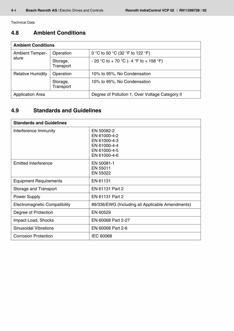
4.8 Ambient Conditions
4.9 Standards and Guidelines
Ambient Conditions
Ambient Temper-ature
Operation 0 °C to 50 °C (32 °F to 122 °F)
Storage,Transport
- 20 °C to + 70 °C (- 4 °F to + 158 °F)
Relative Humidity Operation 10% to 95%, No Condensation
Storage,Transport
10% to 95%, No Condensation
Application Area Degree of Pollution 1, Over Voltage Category II
Standards and Guidelines
Interference Immunity EN 50082-2EN 61000-4-2EN 61000-4-3EN 61000-4-4EN 61000-4-5EN 61000-4-6
Emitted Interference EN 50081-1EN 55011EN 55022
Equipment Requirements EN 61131
Storage and Transport EN 61131 Part 2
Power Supply EN 61131 Part 2
Electromagnetic Compatibility 89/336/EWG (Including all Applicable Amendments)
Degree of Protection EN 60529
Impact Load, Shocks EN 60068 Part 2-27
Sinusoidal Vibrations EN 60068 Part 2-6
Corrosion Protection IEC 60068

R911299728 / 02 | Rexroth IndraControl VCP 02 Electric Drives and Controls | Bosch Rexroth AG 4-5
Technical Data
4.10 Compatibility Test
All Rexroth controls and drives are developed and tested according tothe technological state-of-the-art.
As it is impossible to follow the continuing development of all materials(e.g. lubricants in machine tools) which may interact with our controlsand drives, it cannot be completely ruled out that any reactions with thematerials used by Bosch Rexroth might occur.
For this reason, before using the respective material a compatibilitytest has to be carried out for new lubricants, cleaning agents etc. andour housings/our housing materials.

4-6 Bosch Rexroth AG | Electric Drives and Controls Rexroth IndraControl VCP 02 | R911299728 / 02
Technical Data

R911299728 / 02 | Rexroth IndraControl VCP 02 Electric Drives and Controls | Bosch Rexroth AG 5-1
Dimensions
5 Dimensions
5.1 Installation
The operator terminal can be easily and quickly mounted from the rearof the operator terminal. This is particularly recommended for mountingin switchboards with a plate thickness of approx. 1 mm to 6 mm(approx. 0.039" to 0.236").
1. Insert the operator terminal from the front through the mounting cut-out.
2. Fasten the operator terminal using hexagon nuts.
When installing the operator terminal, keep a minimum clearance of 30 mm (1.181") around the operator terminal to ensure adequate air cir-culation.
When the operator terminal is installed horizontally, please note that ad-ditional sources of heat beneath the operator terminal may result in heat accumulation.Provide for sufficient heat dissipation!Comply with the allowable temperature range listed in the technical data for the use of the operator terminal!
To maintain the specified degree of protection, make sure the seal is evenly seated on the installation surface and the hexagon nuts are tight-ened uniformly.Ensure that the maximum torque of 0.6 Nm is not exceeded.

5-2 Bosch Rexroth AG | Electric Drives and Controls Rexroth IndraControl VCP 02 | R911299728 / 02
Dimensions
5.1.1 Front Panel Dimensions
Fig. 5-1: Front panel dimensions

R911299728 / 02 | Rexroth IndraControl VCP 02 Electric Drives and Controls | Bosch Rexroth AG 5-3
Dimensions
5.1.2 Mounting Cutout
Fig. 5-2: Mounting cutout
A Mounting CutoutB Front Panel

5-4 Bosch Rexroth AG | Electric Drives and Controls Rexroth IndraControl VCP 02 | R911299728 / 02
Dimensions
5.1.3 Side View, Mounting Depth
Fig. 5-3: Side view, mounting depth of standard and field bus device
1 Front Panel2 Circumferential Seal3 Press-in Threaded Bolt M3 x 12 mm (0.709")4 Mounting Surface Thickness 1 mm to 6 mm (0.039" to 0.236")5 Spring Lock Washer B3 DIN 127 Form B (not supplied)6 Nut M3 DIN 934 (not supplied)

R911299728 / 02 | Rexroth IndraControl VCP 02 Electric Drives and Controls | Bosch Rexroth AG 6-1
Display and Operating Components
6 Display and Operating Components
6.1 Display
The operator terminal is equipped with a STN display.
6.1.1 Setting the Contrast
To define the contrast setting, use the programming software to set upthe system variable LcdContrast in any mask.
In the programming software, enter the following values as lower andupper limits for the representation type.
If you did set-up the system variable, you can set the contrast as fol-lows. Open the mask where you set up the system variable and:
1. Press the data release key if the data release is not automatically ac-tive.
2. Enter a new value for the contrast. To do so, use the keys 0-9 or plus and minus.
3. Confirm with Enter.4. Finally press the data release key.The new contrast setting becomes effective immediately after the Enterkey is pressed. If necessary, repeat the steps two and three until youare satisfied with the contrast.
Danger of intoxication!If the display is damaged, avoid touching, swallowing or breathing in the liquids or gases which may leak out.
Danger of corrosion!If the display is damaged, avoid touching, swallowing or breathing in the liquids or gases which may leak out.
To do so, follow the instructions listed in the programming software's help topic "How do I specify the contrast / brightness setting for the op-erating device".
System Variable Lower Limit Upper Limit Default Setting
LcdContrast - 25 + 70 + 25
Fig. 6-1: Values for the representation type
If you do not configure the system variable LcdContrast, the default setting is used when the device is initialized.

6-2 Bosch Rexroth AG | Electric Drives and Controls Rexroth IndraControl VCP 02 | R911299728 / 02
Display and Operating Components
6.1.2 Default Contrast Setting
If the contrast setting is such that it is no longer possible to read themasks, you can use the user mode switch to reset the contrast to thedefault value.
To restore the default contrast:
1. Switch the device off.2. Set the switches S1 and S4 of the user mode switch to ON.3. Switch the device on again.4. When the warning appears, switch the device off again.5. Set switch S4 to OFF.6. Then switch the device on again.The application will not be lost.
6.1.3 Character Attributes
The following character attributes can be displayed on the device:
– Normal– Flashing
6.1.4 Fonts
You are able to use the font "Normal" and the character set"Katakana".
For the table with the switch positions of the user mode switch, see chapter "User Mode Switch".
The switch position for the default contrast is identical with the "Activate download via hardware". The contrast is reset before a corresponding message is displayed. The warning will be displayed in a legible man-ner.
R911299728 / 02 | Rexroth IndraControl VCP 02 Electric Drives and Controls | Bosch Rexroth AG 6-3
Display and Operating Components
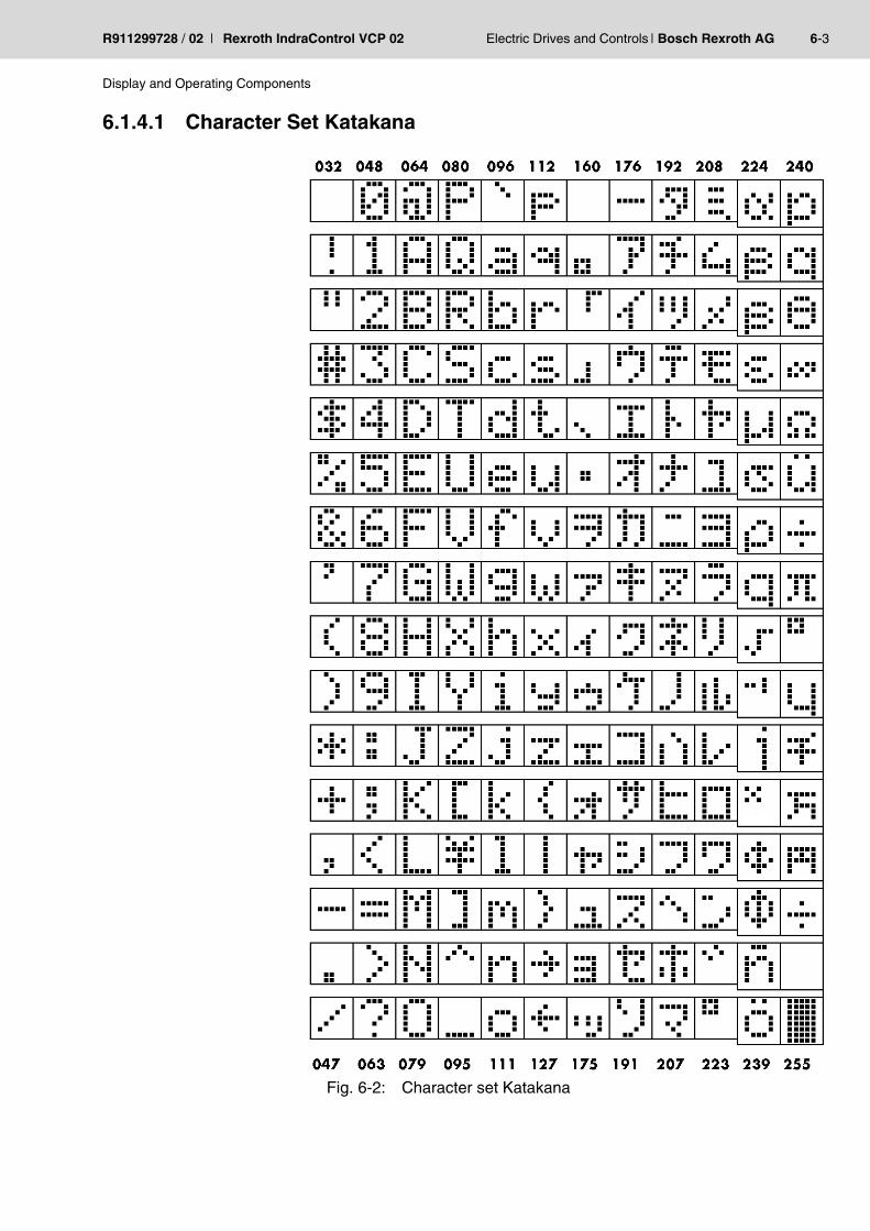
6.1.4.1 Character Set Katakana
Fig. 6-2: Character set Katakana

6-4 Bosch Rexroth AG | Electric Drives and Controls Rexroth IndraControl VCP 02 | R911299728 / 02
Display and Operating Components
6.2 Keyboard
The keys are positioned under an environmental-proof polyester foil.You project the operating principle of the keys in the programming soft-ware.
6.2.1 Edit Keys
To activate the edit mode, you must press the data release key at first.After the status LED „data release“ lights up an input with the edit keysis possible.
6.2.2 Navigation Keys
The key Minus is used to enter negative values within the editor. In the increment editor, the variable value is decreased by 1. When the key is held down, the function is repeated at an automatically increasing rate of repetition.
The key Plus is used to enter positive values within the editor. In the in-crement editor, the variable value is increased by 1. When the key is held down, the function is repeated at an automatically increasing rate of repetition.
The key Cursor left can be programmed to directly select adjacent nodes and I/O masks. In the editor it moves the cursor one character to the left (character selection).
The key Cursor down can be programmed to directly select adjacent nodes and I/O masks. In the editor it moves the cursor down one vari-able (variable selection).

R911299728 / 02 | Rexroth IndraControl VCP 02 Electric Drives and Controls | Bosch Rexroth AG 6-5
Display and Operating Components
6.2.3 Special Keys
6.2.4 Function Keys
6.2.4.1 Slide-in Identification Strips for the Function Keys
The identifications strips can be replaced when the operating device isremoved. Inserting the strip from the rear side of the front plate doesnot influence the specified seal of the operator terminal. A set of identi-fication strips is supplied with the operator terminal.
For the labeling use:
The key Help always shows the current help text (online help). A flash-ing help LED indicates that theere is a message. The system message is always shown in plain text.
The key Data release changes from the menu to the editor. The inte-grated LED is lit during edit mode. Pressing data release in edit mode exits the editor.
The key Enter is used to end the data entry. Pressing it during the start mask opens the setup mask.
The function of the function keys can be freely assigned (with soft key functions). The function keys can used either as direct keys for menu control of for triggering a function in the control system.
Single pieces, prototypes Label with a water-resistant pen
Small series Copying foil with laser print
Large series Customer-specific labeled identification strips

6-6 Bosch Rexroth AG | Electric Drives and Controls Rexroth IndraControl VCP 02 | R911299728 / 02
Display and Operating Components
Fig. 6-3: Identification strip set VCP 02
Fig. 6-4: Position of the identification strips

R911299728 / 02 | Rexroth IndraControl VCP 02 Electric Drives and Controls | Bosch Rexroth AG 6-7
Display and Operating Components
6.3 User Mode Switch
The user mode switch is located on the rear of the small operator termi-nal.
Legend for table:
I = Switch ON
– = Switch OFF
X = Any switch position
The switch positions for ON or OFF are printed onto the user mode switch.
S1 S2 S3 S4 Operating Mode
I X – – Standard mode with PLC (default upon delivery)
I X I – Standard mode without PLC
– I – – Transparent mode with start- and stop code of the keys
– – – I Transparent mode without stop code of the keys
I – – I Activate download (erases the application mem-ory) and default contrast / brightness setting
I – I I Activate upload
Fig. 6-5: User mode switch

6-8 Bosch Rexroth AG | Electric Drives and Controls Rexroth IndraControl VCP 02 | R911299728 / 02
Display and Operating Components

R911299728 / 02 | Rexroth IndraControl VCP 02 Electric Drives and Controls | Bosch Rexroth AG 7-1
Interfaces
7 InterfacesThe device can either be supplied as a standard device or field busdevice.
Depending on the device variant, several interfaces are available toyou:
Type code Available interfaces
RS
232c
(X
3)
TT
Y /
20m
A, R
S48
5, R
S23
2c(X
2-S
ER
1/S
ER
2)IN
TE
RB
US
PR
OF
IBU
S D
P
VCPxx.xxxx-xxxRS-xx-xx - X - -
VCPxx.xxxx-xxxIB-xx-xx X - X -
VCPxx.xxxx-xxxPB-xx-xx X - - X
Fig. 7-1: Device variants

7-2 Bosch Rexroth AG | Electric Drives and Controls Rexroth IndraControl VCP 02 | R911299728 / 02
Interfaces
7.1 Standard Interfaces
The universal interface X2 combines several interface standards in oneconnector. The connector is divided into two channels. The communi-cation channel (SER1) is operated separately from the channel for theupload/download/logging printer/scanner (SER2).
For the communication channel (SER1), the protocol-specific use onlyallows one of the three interface standards to be used.
Fig. 7-2: Rear view of standard device
1. Fastening Screws2. Mounting Bolt3. Front Panel4. Nameplate5. Battery-related information6. Warning7. Assignment Connector X1 (Supply Voltage)8. Connector X1 (Supply Voltage)9. Assignment for User Mode Switch10. User Mode Switch11. Threaded Bolt for Protective Grounding12. Assignment for Termination Switch (X2-SER1 RS485)13. Termination Switch (X2-SER1 RS485)14. Assignment Connector X2 (TTY/RS485/RS232c)15. Female Connector X2 (TTY/RS485/RS232c)

R911299728 / 02 | Rexroth IndraControl VCP 02 Electric Drives and Controls | Bosch Rexroth AG 7-3
Interfaces
7.1.1 TTY / 20 mA Current Loop (X2-SER1)
Depending on the wiring, it is possible to connect the interface either asan active or passive current loop. The transmit line and the receive lineare each provided with a separate 20 mA power source. The compli-ance voltage is approx. 24 VDC.
The 20 mA power should be supplied by the transmitter unit. Thisdecreases crosstalk on the signal lines considerably.
In idle state (signal logic 1), a 20 mA current loop can be measured inthe cable.
7.1.1.1 Pin Assignment
Fig. 7-3: 25 pin D-SUB female connector strip
Connector in the small operator terminal: 25-pin D-SUB female con-nector strip
Signal Logic 1 Current Flow 20 mA
Signal Logic 0 Current Flow Interrupted
Pin Designation Function
10 T+ Transmitted Data, Positive Polarity
13 R+ Received Data, Positive Polarity
14 R- Received Data, Negative Polarity
19 T- Transmitted Data, Negative Polarity
Fig. 7-4: Pin assignment TTY / 20 mA, passive

7-4 Bosch Rexroth AG | Electric Drives and Controls Rexroth IndraControl VCP 02 | R911299728 / 02
Interfaces
7.1.1.2 Termination
Pin Designation Function
10 T+ Transmitted Data, Positive Polarity
12 S1+ Power Source 1, Positive Polarity
13 R+ Received Data, Positive Polarity
14 R- Received Data, Negative Polarity
16 S2+ Power Source 2, Positive Polarity
19 T- Transmitted Data, Negative Polarity
21 S1- Current Sink 1, Negative Polarity
24 S2- Current Sink 2, Negative Polarity
Fig. 7-5: Pin assignment TTY / 20 mA, active
The D-SUB connector strips must be shielded sufficiently. See chapter “Shielding D-SUB Connectors“ on page 7-16.
When channel SER1 is operated as a current loop, the termination for the RS485 must be OFF.

R911299728 / 02 | Rexroth IndraControl VCP 02 Electric Drives and Controls | Bosch Rexroth AG 7-5
Interfaces
7.1.2 RS485 (X2-SER1)
The interface is suitable for point-to-point and for multi-point connec-tions.
The wires belonging together are marked with „A“ and „B“. Somedescriptions refer to the pins with „+“ and „-“ , where A = + and B = -.
7.1.2.1 Pin Assignment
Fig. 7-6: 25 pin D-SUB female connector strip
Connector in the small operator terminal: 25-pin D-SUB female con-nector strip
7.1.2.2 Termination
For point-to-point connections, always activate the termination. Formulti-point connections, only activate the termination at the cable end.
Signal Logic 1 UA - UB <= -0.3 V i.e. (UA < UB)
Signal Logic 0 UA - UB >= +0.3 V i.e. (UA > UB)
Pin Designation Function
8 T(A) Transmitted data (+)
9 T(B) Transmitted data (-)
11 SGND Signal Ground
22 R(A) Received data (+)
23 R(B) Received data (-)
Fig. 7-7: Pin assignment RS485
The D-SUB connector strips must be shielded sufficiently. See chapter “Shielding D-SUB Connectors“ on page 7-16.

7-6 Bosch Rexroth AG | Electric Drives and Controls Rexroth IndraControl VCP 02 | R911299728 / 02
Interfaces
Fig. 7-8: Block diagram termination RS485
Legend for table:
I = Switch ON
- = Switch OFF
Designation Value
R1, R3 510 Ohm
R2 150 Ohm
R4 120 Ohm
Fig. 7-9: Resistance values termination RS485
The switch positions for ON or OFF are printed onto the termination switch. Only the specified switch positions are permitted.
S1 S2 S3 S4 Function
Transmitter Receiver
I I I I Termination is ON
– – – – Termination is OFF
Fig. 7-10: Termination switch

R911299728 / 02 | Rexroth IndraControl VCP 02 Electric Drives and Controls | Bosch Rexroth AG 7-7
Interfaces
7.1.3 RS232c (X2-SER1)
The interface is suitable to establish a point-to-point connection.
7.1.3.1 Pin Assignment
Fig. 7-11: 25 pin D-SUB female connector strip
Connector in the small operator terminal: 25-pin D-SUB female con-nector strip
7.1.3.2 Termination
Pin Designation Function
6 TD Transmitted Data
15 CTS Clear to Send
17 RTS Request to Send
18 RD Received Data
25 SGND Signal Ground
Fig. 7-12: Pin assignment RS232c
The D-SUB connector strips must be shielded sufficiently. See chapter “Shielding D-SUB Connectors“ on page 7-16.
For the operation of channel SER1 as a RS232, the termination for the RS485 must be OFF.

7-8 Bosch Rexroth AG | Electric Drives and Controls Rexroth IndraControl VCP 02 | R911299728 / 02
Interfaces
7.1.4 RS232c (X2-SER2)
The interface is only designed to be used for downloads, uploads, ascanner or a logging printer because the interface is not electrically iso-lated.
7.1.4.1 Pin Assignment
Fig. 7-13: 25-pin D-SUB female connector strip
Connector in the small operator terminal: 25-pin D-SUB female con-nector strip
Pin Designation Function
1 Low-Noise Ground
2 TD Transmitted Data
3 RD Received Data
4 RTS Request to Send
5 CTS Clear to Send
7 SGND Signal Ground
20 DTR Data Transfer Request
Fig. 7-14: Pin assignment of the RS232c interface
The D-SUB connector strips must be shielded sufficiently. See chapter “Shielding D-SUB Connectors“ on page 7-16.

R911299728 / 02 | Rexroth IndraControl VCP 02 Electric Drives and Controls | Bosch Rexroth AG 7-9
Interfaces
7.2 Field Bus Interfaces
7.2.1 INTERBUS (X2) and RS232c (X3)
The device can be integrated into the INTERBUS using the interfacesavailable for INTERBUS connections.
Fig. 7-15: Rear view INTERBUS
1 Fastening Screws2 Mounting Bolt3 Front Panel4 Battery-related information5 Warning6 Nameplate7 Threaded Bolt for Protective Grounding8 Assignment Connector X1 (Supply Voltage)9 Connector X1 (Supply Voltage)10 Assignment Female Connector X3 (RS232c)11 Female Connector X3 (RS232c)12 Assignment Female Connector X2.2 (Remotebus out)13 Female Connector X2.2 (Remotebus out)14 Assignment Male Connector X2.1 (Remotebus in)15 Male Connector X2.1 (Remotebus in)16 User Mode Switch17 Assignment for User Mode Switch18 Diagnostic LEDs

7-10 Bosch Rexroth AG | Electric Drives and Controls Rexroth IndraControl VCP 02 | R911299728 / 02
Interfaces
7.2.1.1 Pin Assignment
Fig. 7-16: 9-pin D-SUB male and female connector strip
Connector in the small operator terminal: 9-pin D-SUB male connectorstrip for remote bus in.
Connector in the small operator device: 9-pin D-SUB female connectorstrip for remote bus out.
The interface X3 is only designed to be used for downloads, uploads, ascanner or a logging printer because the interface is not electrically iso-lated.
Pin Designation Function
1 DO Data Output
2 DI Data Input
3 GND Ground
4 nc Not Connected
5 nc Not Connected
6 /DO Data Output, Inverted
7 /DI Data Input, Inverted
8 nc Not Connected
9 nc Not Connected
Fig. 7-17: Pin assignment INTERBUS
Pin Designation Function
1 DO Data Output
2 DI Data Input
3 GND Ground
4 nc Not Connected
5 +5 V Power Supply +5 VDC
6 /DO Data Output, Inverted
7 /DI Data Input, Inverted
8 nc Not Connected
9 RBST Remote Bus Status
Fig. 7-18: Pin assignment INTERBUS

R911299728 / 02 | Rexroth IndraControl VCP 02 Electric Drives and Controls | Bosch Rexroth AG 7-11
Interfaces
Connector in the small operator device: 9-pin D-SUB female connectorstrip.
7.2.1.2 Cable
7.2.1.3 Diagnostics
The diagnostic LEDs are located at the rear of the small operator termi-nal. The LEDs show the states of the bus system.
Fig. 7-20: Arrangement of the INTERBUS diagnostic LEDs
The diagnostic LEDs at the small operator terminal has the followingfunctions:
Pin Designation Function
1 nc Not Connected
2 RD Received Data
3 TD Transmitted Data
4 DTR Data Transfer Request
5 SGND Signal Ground
6 nc Not Connected
7 RTS Request to Send
8 CTS Clear to Send
9 nc Not Connected
Fig. 7-19: Pin assignment RS232c
The D-SUB connector strips must be shielded sufficiently. See chapter “Shielding D-SUB Connectors“ on page 7-16.
A shielded twisted-pair cable (cable type LiYCY-TP) must be used. The maximum cable length depends on its use within the INTERBUS topol-ogy.
Designation Color State Function
RC Green On Remote Bus Check
+5 V Green On Supply Voltage OK
Off No Supply Voltage
Fig. 7-21: Functions of the INTERBUS diagnostic LEDs

7-12 Bosch Rexroth AG | Electric Drives and Controls Rexroth IndraControl VCP 02 | R911299728 / 02
Interfaces
BA Green On Bus Active
Off Bus Not Active
RD Red On Remote Bus Inactive
Designation Color State Function
Fig. 7-21: Functions of the INTERBUS diagnostic LEDs

R911299728 / 02 | Rexroth IndraControl VCP 02 Electric Drives and Controls | Bosch Rexroth AG 7-13
Interfaces
7.2.2 PROFIBUS DP (X2) and RS232c (X3)
The interface for PROFIBUS DP connections is available to integratethe device into a PROFIBUS DP structure.
Fig. 7-22: Rear view PROFIBUS DP
1. Fastening Screws2. Mounting Bolt3. Front Panel4. Nameplate5. Battery-related information6. Warning7. Assignment Connector X1 (Supply Voltage)8. Connector X1 (Supply Voltage)9. Assignment for User Mode Switch10. User Mode Switch11. Threaded Bolt for Protective Grounding12. Assignment Female Connector X3 (RS232c)13. Female Connector X3 (RS232c)14. Assignment Female Connector X2 (PROFIBUS DP)15. Female Connector X2 (PROFIBUS DP)16. Diagnostic LED

7-14 Bosch Rexroth AG | Electric Drives and Controls Rexroth IndraControl VCP 02 | R911299728 / 02
Interfaces
7.2.3 Pin Assignment
Fig. 7-23: 9-pin D-SUB male and female connector strip
Connector in the small operator terminal: 9-pin D-SUB female connec-tor strip.
The interface X3 should only be used for download, upload, scannerand logging printer, due to not electrically isolated interface.
Connector in the small operator terminal: 25-pin D-SUB female con-nector strip.
Pin Designation Function
1 nc Not Connected
2 nc Not Connected
3 RxD/TxD-P Received Data / Transmitted Data Plus
4 CNTR-P Repeater Control Signal Plus
5 DGND Data Transmission Potential
6 VP Supply Voltage of Terminators Plus
7 nc Not Connected
8 RxD/TxD-N Received Data / Transmitted Data Minus
9 CNTR-N Repeater Control Signal Minus
Fig. 7-24: Pin assignment PROFIBUS DP
Pin Designation Function
1 nc Not Connected
2 TD Transmitted Data
3 RD Received Data
4 RTS Request to Send
5 CTS Clear to Send
7 SGND Signal Ground
20 DTR Data Transfer Request
Fig. 7-25: Pin assignment RS232c
The D-SUB connector strips must be shielded sufficiently. See chapter “Shielding D-SUB Connectors“ on page 7-16.

R911299728 / 02 | Rexroth IndraControl VCP 02 Electric Drives and Controls | Bosch Rexroth AG 7-15
Interfaces
7.2.4 Cable
The maximum cable length depends on the baud rate (DIN EN 19245Part 3).
7.2.5 Termination
Terminate the PROFIBUS at both ends by terminating resistors. If youare using special PROFIBUS connectors, these resistors are usuallyintegrated into the connector and can be connected.
7.2.6 Diagnostics
A diagnostic LED is located on the rear of the small operator terminal.The LED shows a state of the bus system.
Fig. 7-27: Arrangement of the PROFIBUS DP diagnostic LED
The diagnostic LED on the small operator terminal has the followingfunction:
Any PROFIBUS DP-approved cables specified in the EN 50170 as ca-ble type A can be used.
Impedance 136 to 165 Ohm
Capacity < 30 pf/m
Loop resistance 110 Ohm/km
Wire gauge 0.64 mm
Baud Rate Cable Length
187.5 kbits/s 1000 m
500 kbits/s 400 m
1500 kbits/s 200 m
3000 to 12000 kbits/s 100 m
Fig. 7-26: Baud rate PROFIBUS DP
Color State Function
Green On Communication Active
Fig. 7-28: Function of the PROFIBUS DP diagnostic LED

7-16 Bosch Rexroth AG | Electric Drives and Controls Rexroth IndraControl VCP 02 | R911299728 / 02
Interfaces
7.3 Shielding D-SUB Connectors
You must shield D-SUB connectors as follows:
Fig. 7-29: Shielding D-SUB connectors
1 D-SUB connector2 Shield3 Cable clip4 CableThe shield must be folded back into a flat position over the cablesheath.
When fastening the cable with the cable clip, as much of the shieldingas possible must be in contact with the housing and sufficient strainrelieve must be ensured.

R911299728 / 02 | Rexroth IndraControl VCP 02 Electric Drives and Controls | Bosch Rexroth AG 8-1
Maintenance and Installation
8 Maintenance and Installation
8.1 General Information
VCP-type operator terminals are maintenance-free. A few parts aresubject to wear and must be replaced after a certain number of operat-ing hours.
8.2 Exchange of Hardware Components
8.3 Data Backup
8.4 Unpacking the Device
Unpack all parts carefully and check the contents for any visible trans-port damage. Also check whether the shipment matches the specifica-tions on your delivery note.
If you notice transport damages or discrepancies, please contact oursales department immediately.
CAUTIONMaintenance work in the device is only permissible by skilled stuff!If hardware components have to be exchanged, please contact the Bosch Rexroth Service or ensure that only skilled stuff changes the re-spective components.
CAUTIONThe Bosch Rexroth AG is not liable for possible data loss and the damages resulting from this!The customer himself is responsible for the backup of customer-specific data and must provide this data in case of service.

8-2 Bosch Rexroth AG | Electric Drives and Controls Rexroth IndraControl VCP 02 | R911299728 / 02
Maintenance and Installation
8.5 Identification
You can identify the small operator terminal by the nameplate on therear.
Fig. 8-1: Nameplate (example)
1 Ordering name / Short type designation2 Part number3 Voltage and power specification4 Serial numberDepending on the size of the display, you will be able to read varioustypes of information as the operating device is initialized: clock fre-quency, application memory size, current firmware version, program-ming software version, project name, time, date, number of compilationruns and a random number.
1. Hold down an arbitrary key at the operator terminal to generate an error message.
2. Read the firmware version now.3. Release the key to complete the initialization procedure of the oper-
ator terminal.
Because the initialization mask is visible only for a few seconds there is a possibility to represent this mask for a longer time period.

R911299728 / 02 | Rexroth IndraControl VCP 02 Electric Drives and Controls | Bosch Rexroth AG 8-3
Maintenance and Installation
8.6 Connecting
8.6.1 Supply Voltage 24 V
The supply voltage is supplied via connector X1.
The device has reverse polarity protection. In case of wrong polarity,the device will not operate.
This is a protection class I device. For safe operation, safety extra-lowvoltage (SELV) in accordance with DIN EN 61131 must be used for thesupply voltage.
Connector in the terminal: 3-pin connector Phoenix COMBICONMSTBV 2,5/3-GF.
A suitable female connector strip of the type Phoenix COMBICONMSTB 2,5/3-STF is supplied.
Pin Designation Function
1 Low-Noise Ground
2 0 V Supply Voltage 0 V
3 24 VDC Supply Voltage 24 VDC
Fig. 8-2: Pin assignment supply voltage
A cable with finely stranded wires with a minimum cross-section of 0.75 mm² (18 AWG) and a maximum cross-section of 2.5 mm² (14 AWG) must be used for the supply voltage.
WARNINGHazardous voltages can exist inside electrical installations that can pose a danger to humans. Coming in contact with live parts may result in electric shock!
8-4 Bosch Rexroth AG | Electric Drives and Controls Rexroth IndraControl VCP 02 | R911299728 / 02
Maintenance and Installation
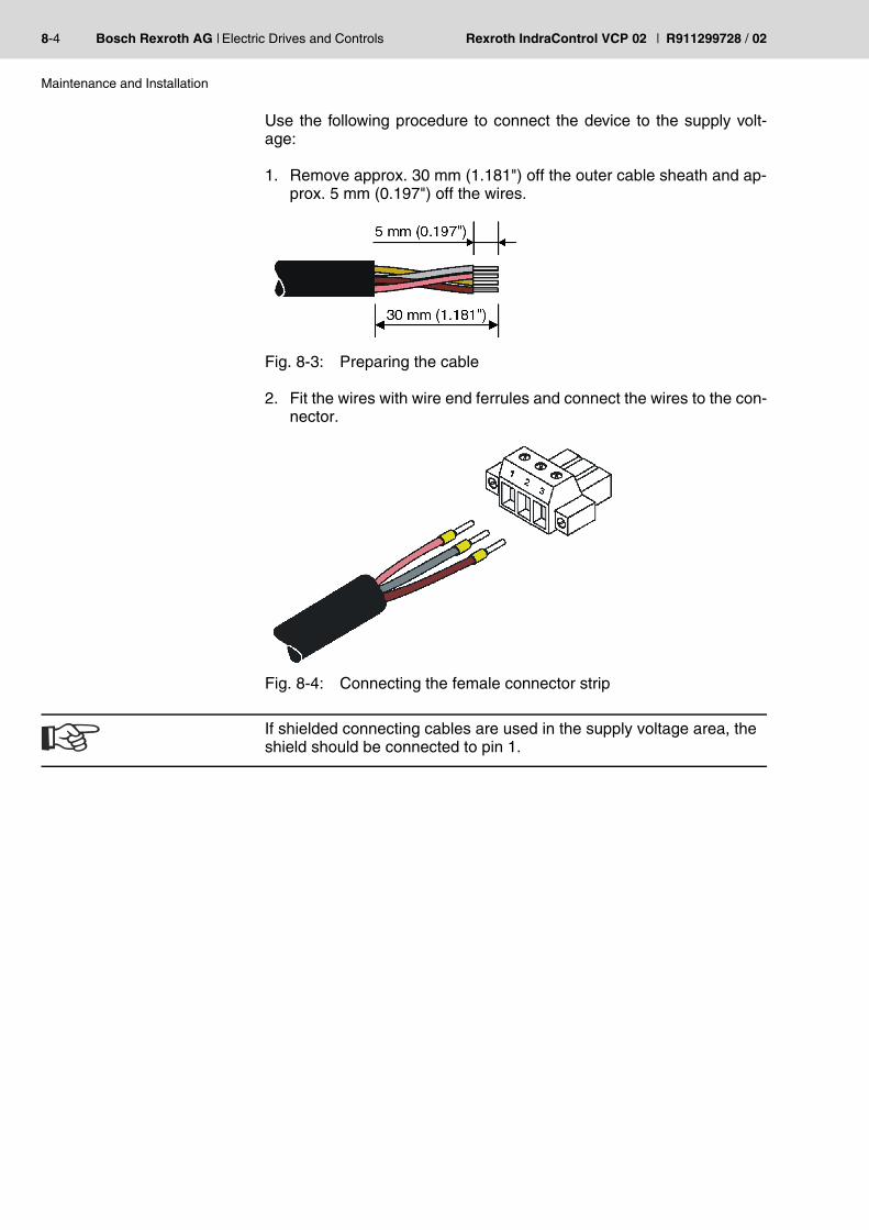
Use the following procedure to connect the device to the supply volt-age:
1. Remove approx. 30 mm (1.181") off the outer cable sheath and ap-prox. 5 mm (0.197") off the wires.
Fig. 8-3: Preparing the cable
2. Fit the wires with wire end ferrules and connect the wires to the con-nector.
Fig. 8-4: Connecting the female connector strip
If shielded connecting cables are used in the supply voltage area, the shield should be connected to pin 1.

R911299728 / 02 | Rexroth IndraControl VCP 02 Electric Drives and Controls | Bosch Rexroth AG 8-5
Maintenance and Installation
3. Plug the female connector strip onto connector X1.A.
Fig. 8-5: Female connector strip is plugged on
4. Secure the female connector strip in place with a screw-type locking to prevent it from slipping out.
8.7 Front Panel
You should use a damp cloth only to remove any dirt from the panel.
8.8 Fuse
A semiconductor fuse is used to protect the device. Once the fuse hasbeen tripped, the device must be disconnected from the supply voltageto allow the semiconductor fuse to regenerate. At an ambient tempera-ture of 20 °C (68° F), the regeneration takes approximately 20 sec-onds. The higher the ambient temperature, the longer the regenerationtakes.
A separate conductor must always be provided for the protective grounding at the threaded bolt. The conductor must have a minimum cross-section of 1.5 mm² (16 AWG) and must be kept as short as pos-sible. Complying with this will increase operating safety.
The semiconductor fuse cannot be replaced!

8-6 Bosch Rexroth AG | Electric Drives and Controls Rexroth IndraControl VCP 02 | R911299728 / 02
Maintenance and Installation
8.9 Battery
The built-in battery preserves the data in the CMOS-RAM and suppliesthe real-time clock. The minimum battery life is 5 years, even underunfavorable operating conditions. When the battery runs down, themessage "Change battery" is generated automatically.
We recommend you change the battery approximately every 4 yearsas part of the regular maintenance work. A pre-assembled batteryincluding connector can be obtained directly from Bosch Rexroth.
If the "Change battery" message is detected too late, e.g. the real-timeclock stopped or shows the wrong date, data in the CMOS-RAM mayhave already been lost. For this reason, after changing a battery,always check data such as passwords that can be modified, parame-ters in the system variables, recipe data sets and entries in the mes-sage system.
8.9.1 Changing the Battery
To ensure that the data in the CMOS-RAM and the time are preserved,it is possible to change the battery under operating voltage. Observethe safety notes!
1. Remove the threaded bolts of the interfaces.2. Remove the screws on the rear panel of the device and lift off the
housing.3. Disconnect the connector from the battery and remove the dead bat-
tery.4. Plug in the cable of the new battery.5. Place the rear panel back onto the device.6. Carefully tighten the screws of the rear panel and then the threaded
bolts of the interfaces.
8.9.2 Battery Disposal
You must always return old batteries to a dealer or to a returns depotset up for this purpose by the public waste disposal body or a licensedbattery dealer for recycling. Only dispose of dead batteries in public orcommercial collection boxes. The battery is drained when the message„Change battery“ appears on the display of the device.
To prevent short circuitry in the collection boxes, insulate the poles of each battery with insulation tape or put each single battery into a plastic bag.

R911299728 / 02 | Rexroth IndraControl VCP 02 Electric Drives and Controls | Bosch Rexroth AG 9-1
Ordering Information
9 Ordering Information
9.1 Type Code
The small operator terminals VCP 02 are available in different variants.Type code:
Fig. 9-1: Type code of the VCP 02
� � � � � � � �� � � � � � � � �
� � � � � � � � �
� � � � � � � � �
�
�� �����
�����������
� � � � � � � � � � � � � � � � ��
� ��������� ������������������ �����
�� ������ ���������������������������������� ���
�� ��������� � ������������������������������������������� ���
�� ������������������������ !"�� #�$!%&�������'& ( '%�(")
���*�#" ����������������������������������� ����
�� ��������������� +,+� ����������������������������������������������� ���
!� "����#������ -�.���/�������������������������������������������� ��-���� ��0�-�/�� � ����������������������������������� ������� ��(! ��1�����2��3�..4���56 ��������� ����
$�� ������������������� +,+� ��������������������������������������������������������������� ����
%� ����&������ �+,%�"�%& %�7!(�$ (���8"%�9��,(:�(�:� "�"�� ( %��"89�,"!%!,+�����
9-2 Bosch Rexroth AG | Electric Drives and Controls Rexroth IndraControl VCP 02 | R911299728 / 02
Ordering Information
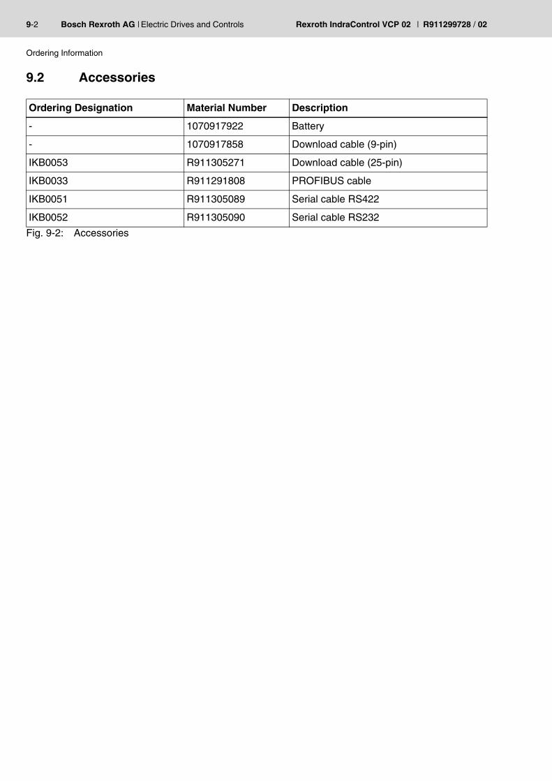
9.2 Accessories
Ordering Designation Material Number Description
- 1070917922 Battery
- 1070917858 Download cable (9-pin)
IKB0053 R911305271 Download cable (25-pin)
IKB0033 R911291808 PROFIBUS cable
IKB0051 R911305089 Serial cable RS422
IKB0052 R911305090 Serial cable RS232
Fig. 9-2: Accessories

R911299728 / 02 | Rexroth IndraControl VCP 02 Electric Drives and Controls | Bosch Rexroth AG 10-1
List of Figures
10 List of FiguresFig. 1-1: VCP 02 with keyboard 1-1Fig. 3-1: Hazard classification (according to ANSI Z535) 3-1Fig. 5-1: Front panel dimensions 5-2Fig. 5-2: Mounting cutout 5-3Fig. 5-3: Side view, mounting depth of standard and field bus device 5-4Fig. 6-1: Values for the representation type 6-1Fig. 6-2: Character set Katakana 6-3Fig. 6-3: Identification strip set VCP 02 6-6Fig. 6-4: Position of the identification strips 6-6Fig. 6-5: User mode switch 6-7Fig. 7-1: Device variants 7-1Fig. 7-2: Rear view of standard device 7-2Fig. 7-3: 25 pin D-SUB female connector strip 7-3Fig. 7-4: Pin assignment TTY / 20 mA, passive 7-3Fig. 7-5: Pin assignment TTY / 20 mA, active 7-4Fig. 7-6: 25 pin D-SUB female connector strip 7-5Fig. 7-7: Pin assignment RS485 7-5Fig. 7-8: Block diagram termination RS485 7-6Fig. 7-9: Resistance values termination RS485 7-6Fig. 7-10: Termination switch 7-6Fig. 7-11: 25 pin D-SUB female connector strip 7-7Fig. 7-12: Pin assignment RS232c 7-7Fig. 7-13: 25-pin D-SUB female connector strip 7-8Fig. 7-14: Pin assignment of the RS232c interface 7-8Fig. 7-15: Rear view INTERBUS 7-9Fig. 7-16: 9-pin D-SUB male and female connector strip 7-10Fig. 7-17: Pin assignment INTERBUS 7-10Fig. 7-18: Pin assignment INTERBUS 7-10Fig. 7-19: Pin assignment RS232c 7-11Fig. 7-20: Arrangement of the INTERBUS diagnostic LEDs 7-11Fig. 7-21: Functions of the INTERBUS diagnostic LEDs 7-11Fig. 7-22: Rear view PROFIBUS DP 7-13Fig. 7-23: 9-pin D-SUB male and female connector strip 7-14Fig. 7-24: Pin assignment PROFIBUS DP 7-14Fig. 7-25: Pin assignment RS232c 7-14Fig. 7-26: Baud rate PROFIBUS DP 7-15Fig. 7-27: Arrangement of the PROFIBUS DP diagnostic LED 7-15Fig. 7-28: Function of the PROFIBUS DP diagnostic LED 7-15Fig. 7-29: Shielding D-SUB connectors 7-16Fig. 8-1: Nameplate (example) 8-2Fig. 8-2: Pin assignment supply voltage 8-3Fig. 8-3: Preparing the cable 8-4Fig. 8-4: Connecting the female connector strip 8-4Fig. 8-5: Female connector strip is plugged on 8-5Fig. 9-1: Type code of the VCP 02 9-1Fig. 9-2: Accessories 9-2

10-2 Bosch Rexroth AG | Electric Drives and Controls Rexroth IndraControl VCP 02 | R911299728 / 02
List of Figures

R911299728 / 02 | Rexroth IndraControl VCP 02 Electric Drives and Controls | Bosch Rexroth AG 11-1
Index
11 IndexBBattery 8-6Battery disposal 8-6
CCable
INTERBUS 7-11PROFIBUS DP 7-15
Changing the battery 8-6Character attributes 6-2Character set
Katakana 6-2, 6-3Normal 6-2
Compatibility test 4-5Connecting 8-3
DDefault contrast setting 6-2Device variants 7-1Diagnostics
INTERBUS 7-11PROFIBUS DP 7-15
FFuse 8-5
IIdentification 8-2
KKey
Cursor down 6-4Cursor left 6-4Data release 6-5Enter 6-5Help 6-5Minus 6-4Plus 6-4
Keyboard 6-4Edit keys 6-4Function keys 6-5Navigation Keys 6-4Special keys 6-5
11-2 Bosch Rexroth AG | Electric Drives and Controls Rexroth IndraControl VCP 02 | R911299728 / 02
Index
LLcdContrast 6-1
NNameplate 8-2
PPin assignment
INTERBUS 7-10PROFIBUS DP 7-14RS232c 7-7, 7-8RS485 7-5TTY / 20 mA 7-3
SSetting the contrast 6-1Standards 4-4Supply voltage 24 V 8-3
TTermination
PROFIBUS DP 7-15RS232c 7-7RS485 7-5TTY / 20 mA 7-4
Termination switch 7-6
UUnpacking 8-1User mode switch 6-7

R911299728 / 02 | Rexroth IndraControl VCP 02 Electric Drives and Controls | Bosch Rexroth AG 12-1
Service & Support
12 Service & Support
12.1 Helpdesk
12.2 Service-Hotline
12.3 Internet
Unser Kundendienst-Helpdesk im Hauptwerk Lohr am Main steht Ihnen mit Rat und Tat zur Seite. Sie erreichen uns
Our service helpdesk at our headquarters in Lohr am Main, Germany can assist you in all kinds of inquiries.Contact us
- telefonisch - by phone: 49 (0) 9352 40 50 60über Service Call Entry Center Mo-Fr 07:00-18:00- via Service Call Entry Center Mo-Fr 7:00 am - 6:00 pm
- per Fax - by fax: +49 (0) 9352 40 49 41
- per e-Mail - by e-mail: [email protected]
Außerhalb der Helpdesk-Zeiten ist der Servicedirekt ansprechbar unter
After helpdesk hours, contact our servicedepartment directly at
+49 (0) 171 333 88 26oder - or +49 (0) 172 660 04 06
Unter www.boschrexroth.com finden Sieergänzende Hinweise zu Service, Reparatur und Training sowie die aktuellen Adressen *) unserer auf den folgenden Seiten aufgeführten Vertriebs-und Servicebüros.
VerkaufsniederlassungenNiederlassungen mit Kundendienst
Außerhalb Deutschlands nehmen Sie bitte zuerst Kontakt mit unserem für Sie nächstgelegenen Ansprechpartner auf.
*) Die Angaben in der vorliegenden Dokumentation können seit Drucklegung überholt sein.
At www.boschrexroth.com you may findadditional notes about service, repairs and training in the Internet, as well as the actual addresses *) of our sales- and service facilities figuring on the following pages.
sales agenciesoffices providing service
Please contact our sales / service office in your area first.
*) Data in the present documentation may have becomeobsolete since printing.

12-2 Bosch Rexroth AG | Electric Drives and Controls Rexroth IndraControl VCP 02 | R911299728 / 02
Service & Support
12.4 Vor der Kontaktaufnahme... - Before contacting us...
12.5 Kundenbetreuungsstellen - Sales & Service Facilities
12.5.1 Deutschland - Germany
Wir können Ihnen schnell und effizient helfen wenn Sie folgende Informationen bereithalten:
1. detaillierte Beschreibung der Störung und der Umstände.
2. Angaben auf dem Typenschild derbetreffenden Produkte, insbesondereTypenschlüssel und Seriennummern.
3. Tel.-/Faxnummern und e-Mail-Adresse, unter denen Sie für Rückfragen zu erreichen sind.
For quick and efficient help, please have thefollowing information ready:
1. Detailed description of the failure andcircumstances.
2. Information on the type plate of the affected products, especially type codes and serialnumbers.
3. Your phone/fax numbers and e-mail address, so we can contact you in case of questions.
vom Ausland: (0) nach Landeskennziffer weglassen! from abroad: don’t dial (0) after country code!
Vertriebsgebiet Mitte Germany Centre
Rexroth Indramat GmbHBgm.-Dr.-Nebel-Str. 2 / Postf. 1357 97816 Lohr am Main / 97803 Lohr
Kompetenz-Zentrum Europa
Tel.: +49 (0)9352 40-0 Fax: +49 (0)9352 40-4885
S E R V I C E
C A L L E N T R Y C E N T E R MO – FR
von 07:00 - 18:00 Uhr
from 7 am – 6 pm
Tel. +49 (0) 9352 40 50 60
S E R V I C E
H O T L I N EMO – FR
von 17:00 - 07:00 Uhr from 5 pm - 7 am
+ SA / SO
Tel.: +49 (0)172 660 04 06 o d e r / o r
Tel.: +49 (0)171 333 88 26
S E R V I C E
ERSATZTEILE / SPARESverlängerte Ansprechzeit - extended office time -
nur an Werktagen - only on working days -
von 07:00 - 18:00 Uhr- from 7 am - 6 pm -
Tel. +49 (0) 9352 40 42 22
Vertriebsgebiet Süd Germany South
Bosch Rexroth AG Landshuter Allee 8-10 80637 München
Tel.: +49 (0)89 127 14-0 Fax: +49 (0)89 127 14-490
Vertriebsgebiet West Germany West
Bosch Rexroth AG Regionalzentrum West Borsigstrasse 15 40880 Ratingen
Tel.: +49 (0)2102 409-0 Fax: +49 (0)2102 409-406 +49 (0)2102 409-430
Gebiet Südwest Germany South-West
Bosch Rexroth AG Service-Regionalzentrum Süd-WestSiemensstr.170736 Fellbach
Tel.: +49 (0)711 51046–0 Fax: +49 (0)711 51046–248
Vertriebsgebiet NordGermany North
Bosch Rexroth AG Walsroder Str. 93 30853 Langenhagen
Tel.: +49 (0) 511 72 66 57-0 Service: +49 (0) 511 72 66 57-256 Fax: +49 (0) 511 72 66 57-93 Service: +49 (0) 511 72 66 57-783
Vertriebsgebiet MitteGermany Centre
Bosch Rexroth AG Regionalzentrum Mitte Waldecker Straße 13 64546 Mörfelden-Walldorf
Tel.: +49 (0) 61 05 702-3 Fax: +49 (0) 61 05 702-444
Vertriebsgebiet OstGermany East
Bosch Rexroth AG Beckerstraße 31 09120 Chemnitz
Tel.: +49 (0)371 35 55-0 Fax: +49 (0)371 35 55-333
Vertriebsgebiet OstGermany East
Bosch Rexroth AG Regionalzentrum Ost Walter-Köhn-Str. 4d 04356 Leipzig
Tel.: +49 (0)341 25 61-0 Fax: +49 (0)341 25 61-111

R911299728 / 02 | Rexroth IndraControl VCP 02 Electric Drives and Controls | Bosch Rexroth AG 12-3
Service & Support
12.5.2 Europa (West) - Europe (West)
vom Ausland: (0) nach Landeskennziffer weglassen, Italien: 0 nach Landeskennziffer mitwählen from abroad: don’t dial (0) after country code, Italy: dial 0 after country code
Austria - Österreich
Bosch Rexroth GmbH Electric Drives & Controls Stachegasse 13 1120 Wien
Tel.: +43 (0)1 985 25 40 Fax: +43 (0)1 985 25 40-93
Austria – Österreich
Bosch Rexroth GmbH Electric Drives & Controls Industriepark 18 4061 Pasching
Tel.: +43 (0)7221 605-0 Fax: +43 (0)7221 605-21
Belgium - Belgien
Bosch Rexroth NV/SA Henri Genessestraat 1 1070 Bruxelles
Tel: +32 (0) 2 582 31 80 Fax: +32 (0) 2 582 43 10 [email protected]@boschrexroth.be
Denmark - Dänemark
BEC A/S Zinkvej 6 8900 Randers
Tel.: +45 (0)87 11 90 60 Fax: +45 (0)87 11 90 61
Great Britain – Großbritannien
Bosch Rexroth Ltd. Electric Drives & Controls Broadway Lane, South Cerney Cirencester, Glos GL7 5UH
Tel.: +44 (0)1285 863000 Fax: +44 (0)1285 863030 [email protected]
Finland - Finnland
Bosch Rexroth Oy Electric Drives & Controls Ansatie 6 017 40 Vantaa
Tel.: +358 (0)9 84 91-11 Fax: +358 (0)9 84 91-13 60
France - Frankreich
Bosch Rexroth SAS Electric Drives & Controls Avenue de la Trentaine(BP. 74) 77503 Chelles Cedex
Tel.: +33 (0)164 72-70 00 Fax: +33 (0)164 72-63 00 Hotline: +33 (0)608 33 43 28
France - Frankreich
Bosch Rexroth SAS Electric Drives & Controls ZI de Thibaud, 20 bd. Thibaud (BP. 1751) 31084 Toulouse
Tel.: +33 (0)5 61 43 61 87 Fax: +33 (0)5 61 43 94 12
France – Frankreich
Bosch Rexroth SAS Electric Drives & Controls 91, Bd. Irène Joliot-Curie 69634 Vénissieux – Cedex
Tel.: +33 (0)4 78 78 53 65 Fax: +33 (0)4 78 78 53 62
Italy - Italien
Bosch Rexroth S.p.A. Via G. Di Vittorio, 1 20063 Cernusco S/N.MI
Hotline: +39 02 92 365 563 Tel.: +39 02 92 365 1 Service: +39 02 92 365 326 Fax: +39 02 92 365 500 Service: +39 02 92 365 503
Italy - Italien
Bosch Rexroth S.p.A.Via Paolo Veronesi, 250 10148 Torino
Tel.: +39 011 224 88 11 Fax: +39 011 224 88 30
Italy - Italien
Bosch Rexroth S.p.A.Via Mascia, 1 80053 Castellamare di Stabia NA
Tel.: +39 081 8 71 57 00 Fax: +39 081 8 71 68 85
Italy - Italien
Bosch Rexroth S.p.A.Via del Progresso, 16 (Zona Ind.) 35020 Padova
Tel.: +39 049 8 70 13 70 Fax: +39 049 8 70 13 77
Italy - Italien
Bosch Rexroth S.p.A.Via Isonzo, 61 40033 Casalecchio di Reno (Bo)
Tel.: +39 051 29 86 430 Fax: +39 051 29 86 490
Netherlands - Niederlande/Holland
Bosch Rexroth Services B.V. Technical Services Kruisbroeksestraat 1 (P.O. Box 32) 5281 RV Boxtel
Tel.: +31 (0) 411 65 16 40 +31 (0) 411 65 17 27 Fax: +31 (0) 411 67 78 14 +31 (0) 411 68 28 60 [email protected]
Netherlands – Niederlande/Holland
Bosch Rexroth B.V. Kruisbroeksestraat 1 (P.O. Box 32) 5281 RV Boxtel
Tel.: +31 (0) 411 65 19 51 Fax: +31 (0) 411 65 14 83 www.boschrexroth.nl
Norway - Norwegen
Bosch Rexroth AS Electric Drives & Controls Berghagan 1 or: Box 3007 1405 Ski-Langhus 1402 Ski
Tel.: +47 (0) 64 86 41 00
Fax: +47 (0) 64 86 90 62
Hotline: +47 (0)64 86 94 82 [email protected]
Spain - Spanien
Bosch Rexroth S.A. Electric Drives & Controls Centro Industrial Santiga Obradors s/n 08130 Santa Perpetua de Mogoda Barcelona
Tel.: +34 9 37 47 94 00 Fax: +34 9 37 47 94 01
Spain – Spanien
Goimendi S.A. Electric Drives & Controls Parque Empresarial Zuatzu C/ Francisco Grandmontagne no.2 20018 San Sebastian
Tel.: +34 9 43 31 84 21 - service: +34 9 43 31 84 56 Fax: +34 9 43 31 84 27 - service: +34 9 43 31 84 60 [email protected]
Sweden - Schweden
Bosch Rexroth AB Electric Drives & Controls - Varuvägen 7 (Service: Konsumentvägen 4, Älfsjö)125 81 Stockholm
Tel.: +46 (0)8 727 92 00 Fax: +46 (0)8 647 32 77
Sweden - Schweden
Bosch Rexroth AB Electric Drives & Controls Ekvändan 7 254 67 Helsingborg
Tel.: +46 (0) 42 38 88 -50 Fax: +46 (0) 42 38 88 -74
Switzerland East - Schweiz Ost
Bosch Rexroth Schweiz AG Electric Drives & Controls Hemrietstrasse 2 8863 Buttikon Tel. +41 (0) 55 46 46 111 Fax +41 (0) 55 46 46 222
Switzerland West - Schweiz West
Bosch Rexroth Suisse SA Av. Général Guisan 26 1800 Vevey 1
Tel.: +41 (0)21 632 84 20 Fax: +41 (0)21 632 84 21

12-4 Bosch Rexroth AG | Electric Drives and Controls Rexroth IndraControl VCP 02 | R911299728 / 02
Service & Support
12.5.3 Europa (Ost) - Europe (East)
vom Ausland: (0) nach Landeskennziffer weglassen from abroad: don’t dial (0) after country code
Czech Republic - Tschechien
Bosch -Rexroth, spol.s.r.o. Hviezdoslavova 5 627 00 Brno
Tel.: +420 (0)5 48 126 358 Fax: +420 (0)5 48 126 112
Czech Republic - Tschechien
DEL a.s. Strojírenská 38 591 01 Zdar nad Sázavou Tel.: +420 566 64 3144 Fax: +420 566 62 1657
Hungary - Ungarn
Bosch Rexroth Kft. Angol utca 341149 Budapest
Tel.: +36 (1) 422 3200 Fax: +36 (1) 422 3201
Poland – Polen
Bosch Rexroth Sp.zo.o. ul. Staszica 1 05-800 Pruszków
Tel.: +48 22 738 18 00 – service: +48 22 738 18 46 Fax: +48 22 758 87 35 – service: +48 22 738 18 42
Poland – Polen
Bosch Rexroth Sp.zo.o. Biuro Poznan ul. Dabrowskiego 81/85 60-529 Poznan
Tel.: +48 061 847 64 62 /-63 Fax: +48 061 847 64 02
Romania - Rumänien
East Electric S.R.L. Bdul Basarabia no.250, sector 3 73429 Bucuresti
Tel./Fax:: +40 (0)21 255 35 07 +40 (0)21 255 77 13 Fax: +40 (0)21 725 61 21 [email protected]
Romania - Rumänien
Bosch Rexroth Sp.zo.o. Str. Drobety nr. 4-10, app. 14 70258 Bucuresti, Sector 2
Tel.: +40 (0)1 210 48 25 +40 (0)1 210 29 50 Fax: +40 (0)1 210 29 52
Russia - Russland
Bosch Rexroth OOO Wjatskaja ul. 27/15 127015 Moskau
Tel.: +7-095-785 74 78 +7-095 785 74 79 Fax: +7 095 785 74 77 [email protected]
Russia - Russland
ELMIS10, Internationalnaya 246640 Gomel, Belarus
Tel.: +375/ 232 53 42 70 +375/ 232 53 21 69 Fax: +375/ 232 53 37 69 [email protected]
Turkey - Türkei
Bosch Rexroth Otomasyon San & Tic. A..S. Fevzi Cakmak Cad No. 3 34630 Sefaköy Istanbul
Tel.: +90 212 541 60 70 Fax: +90 212 599 34 07
Turkey - Türkei
Servo Kontrol Ltd. Sti. Perpa Ticaret Merkezi B BlokKat: 11 No: 1609 80270 Okmeydani-Istanbul
Tel: +90 212 320 30 80 Fax: +90 212 320 30 81 [email protected]
www.servokontrol.com
Slowenia - Slowenien
DOMEL Otoki 21 64 228 Zelezniki
Tel.: +386 5 5117 152 Fax: +386 5 5117 225 [email protected]

R911299728 / 02 | Rexroth IndraControl VCP 02 Electric Drives and Controls | Bosch Rexroth AG 12-5
Service & Support
12.5.4 Afrika, Asien, Australien (inkl. Pazifischer Raum) - Africa, Asia, Australia (incl. Pacific Rim)
Australia - Australien
AIMS - Australian Industrial Machinery Services Pty. Ltd. 28 Westside Drive Laverton North Vic 3026 Melbourne
Tel.: +61 3 93 14 3321 Fax: +61 3 93 14 3329 Hotlines: +61 3 93 14 3321 +61 4 19 369 195 [email protected]
Australia - Australien
Bosch Rexroth Pty. Ltd. No. 7, Endeavour Way Braeside Victoria, 31 95 Melbourne
Tel.: +61 3 95 80 39 33 Fax: +61 3 95 80 17 33 [email protected]
China
Shanghai Bosch Rexroth Hydraulics & Automation Ltd. Waigaoqiao, Free Trade Zone No.122, Fu Te Dong Yi Road Shanghai 200131 - P.R.China
Tel.: +86 21 58 66 30 30 Fax: +86 21 58 66 55 23 [email protected][email protected]
China
Shanghai Bosch Rexroth Hydraulics & Automation Ltd. 4/f, Marine TowerNo.1, Pudong Avenue Shanghai 200120 - P.R.China
Tel: +86 21 68 86 15 88 Fax: +86 21 58 40 65 77
China
Bosch Rexroth China Ltd. 15/F China World Trade Center 1, Jianguomenwai Avenue Beijing 100004, P.R.China
Tel.: +86 10 65 05 03 80 Fax: +86 10 65 05 03 79
China
Bosch Rexroth China Ltd. Guangzhou Repres. Office Room 1014-1016, Metro Plaza, Tian He District, 183 Tian He Bei RdGuangzhou 510075, P.R.China
Tel.: +86 20 8755-0030 +86 20 8755-0011 Fax: +86 20 8755-2387
China
Bosch Rexroth (China) Ltd. A-5F., 123 Lian Shan Street Sha He Kou District Dalian 116 023, P.R.China
Tel.: +86 411 46 78 930 Fax: +86 411 46 78 932
China
Melchers GmbH BRC-SE, Tightening & Press-fit 13 Floor Est Ocean Centre No.588 Yanan Rd. East 65 Yanan Rd. West Shanghai 200001
Tel.: +86 21 6352 8848 Fax: +86 21 6351 3138
Hongkong
Bosch Rexroth (China) Ltd. 6th Floor,Yeung Yiu Chung No.6 Ind Bldg. 19 Cheung Shun Street Cheung Sha Wan, Kowloon, Hongkong
Tel.: +852 22 62 51 00 Fax: +852 27 41 33 44
India - Indien
Bosch Rexroth (India) Ltd. Electric Drives & Controls Plot. No.96, Phase III Peenya Industrial Area Bangalore – 560058
Tel.: +91 80 51 17 0-211...-218 Fax: +91 80 83 94 345 +91 80 83 97 374
India - Indien
Bosch Rexroth (India) Ltd. Electric Drives & Controls Advance House, II FloorArk Industrial Compound Narol Naka, Makwana Road Andheri (East), Mumbai - 400 059
Tel.: +91 22 28 56 32 90 +91 22 28 56 33 18 Fax: +91 22 28 56 32 93
India - Indien
Bosch Rexroth (India) Ltd. S-10, Green Park Extension New Delhi – 110016
Tel.: +91 11 26 56 65 25 +91 11 26 56 65 27 Fax: +91 11 26 56 68 87
Indonesia - Indonesien
PT. Bosch RexrothBuilding # 202, Cilandak Commercial EstateJl. Cilandak KKO, Jakarta 12560
Tel.: +62 21 7891169 (5 lines) Fax: +62 21 7891170 - 71 [email protected]
Japan
Bosch Rexroth Automation Corp.Service Center Japan Yutakagaoka 1810, Meito-ku,NAGOYA 465-0035, Japan
Tel.: +81 52 777 88 41 +81 52 777 88 53 +81 52 777 88 79 Fax: +81 52 777 89 01
Japan
Bosch Rexroth Automation Corp. Electric Drives & Controls 2F, I.R. Building Nakamachidai 4-26-44, Tsuzuki-ku YOKOHAMA 224-0041, Japan
Tel.: +81 45 942 72 10 Fax: +81 45 942 03 41
Korea
Bosch Rexroth-Korea Ltd. Electric Drives and Controls Bongwoo Bldg. 7FL, 31-7, 1Ga Jangchoong-dong, Jung-gu Seoul, 100-391
Tel.: +82 234 061 813 Fax: +82 222 641 295
Korea
Bosch Rexroth-Korea Ltd. 1515-14 Dadae-Dong, Saha-gu Electric Drives & Controls Pusan Metropolitan City, 604-050
Tel.: +82 51 26 00 741 Fax: +82 51 26 00 747 [email protected]
Malaysia
Bosch Rexroth Sdn.Bhd. 11, Jalan U8/82, Seksyen U8 40150 Shah Alam Selangor, Malaysia
Tel.: +60 3 78 44 80 00 Fax: +60 3 78 45 48 00 [email protected] [email protected]
Singapore - Singapur
Bosch Rexroth Pte Ltd 15D Tuas RoadSingapore 638520
Tel.: +65 68 61 87 33 Fax: +65 68 61 18 25 sanjay.nemade
@boschrexroth.com.sg
South Africa - Südafrika
TECTRA Automation (Pty) Ltd.71 Watt Street, Meadowdale Edenvale 1609
Tel.: +27 11 971 94 00 Fax: +27 11 971 94 40Hotline: +27 82 903 29 23 [email protected]
Taiwan
Bosch Rexroth Co., Ltd. Taichung Branch 1F., No. 29, Fu-Ann 5th Street, Xi-Tun Area, Taichung City Taiwan, R.O.C.
Tel : +886 - 4 -23580400 Fax: +886 - 4 -23580402 [email protected]@boschrexroth.com.tw
Thailand
NC Advance Technology Co. Ltd. 59/76 Moo 9 Ramintra road 34 Tharang, Bangkhen,Bangkok 10230
Tel.: +66 2 943 70 62 +66 2 943 71 21 Fax: +66 2 509 23 62 Hotline +66 1 984 61 52 [email protected]
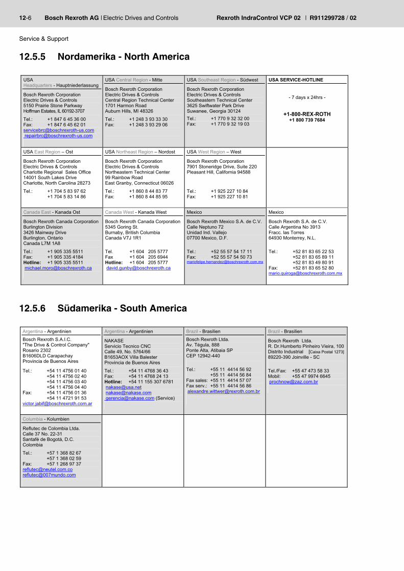
12-6 Bosch Rexroth AG | Electric Drives and Controls Rexroth IndraControl VCP 02 | R911299728 / 02
Service & Support
12.5.5 Nordamerika - North America
12.5.6 Südamerika - South America
USAHeadquarters - Hauptniederlassung
Bosch Rexroth Corporation Electric Drives & Controls 5150 Prairie Stone Parkway Hoffman Estates, IL 60192-3707
Tel.: +1 847 6 45 36 00 Fax: +1 847 6 45 62 01 [email protected] [email protected]
USA Central Region - Mitte
Bosch Rexroth Corporation Electric Drives & Controls Central Region Technical Center 1701 Harmon Road Auburn Hills, MI 48326
Tel.: +1 248 3 93 33 30 Fax: +1 248 3 93 29 06
USA Southeast Region - Südwest
Bosch Rexroth Corporation Electric Drives & Controls Southeastern Technical Center 3625 Swiftwater Park Drive Suwanee, Georgia 30124
Tel.: +1 770 9 32 32 00 Fax: +1 770 9 32 19 03
USA SERVICE-HOTLINE
- 7 days x 24hrs -
+1-800-REX-ROTH+1 800 739 7684
USA East Region – Ost
Bosch Rexroth Corporation Electric Drives & Controls Charlotte Regional Sales Office 14001 South Lakes Drive Charlotte, North Carolina 28273
Tel.: +1 704 5 83 97 62 +1 704 5 83 14 86
USA Northeast Region – Nordost
Bosch Rexroth Corporation Electric Drives & Controls Northeastern Technical Center 99 Rainbow RoadEast Granby, Connecticut 06026
Tel.: +1 860 8 44 83 77 Fax: +1 860 8 44 85 95
USA West Region – West
Bosch Rexroth Corporation 7901 Stoneridge Drive, Suite 220 Pleasant Hill, California 94588
Tel.: +1 925 227 10 84 Fax: +1 925 227 10 81
Canada East - Kanada Ost
Bosch Rexroth Canada Corporation Burlington Division 3426 Mainway Drive Burlington, Ontario Canada L7M 1A8
Tel.: +1 905 335 5511 Fax: +1 905 335 4184 Hotline: +1 905 335 5511 [email protected]
Canada West - Kanada West
Bosch Rexroth Canada Corporation5345 Goring St. Burnaby, British Columbia Canada V7J 1R1
Tel. +1 604 205 5777 Fax +1 604 205 6944 Hotline: +1 604 205 5777 [email protected]
Mexico
Bosch Rexroth Mexico S.A. de C.V.Calle Neptuno 72Unidad Ind. Vallejo 07700 Mexico, D.F.
Tel.: +52 55 57 54 17 11 Fax: +52 55 57 54 50 73 [email protected]
Mexico
Bosch Rexroth S.A. de C.V. Calle Argentina No 3913Fracc. las Torres 64930 Monterrey, N.L.
Tel.: +52 81 83 65 22 53 +52 81 83 65 89 11 +52 81 83 49 80 91 Fax: +52 81 83 65 52 80 [email protected]
Argentina - Argentinien
Bosch Rexroth S.A.I.C. "The Drive & Control Company" Rosario 2302 B1606DLD Carapachay Provincia de Buenos Aires
Tel.: +54 11 4756 01 40 +54 11 4756 02 40 +54 11 4756 03 40 +54 11 4756 04 40 Fax: +54 11 4756 01 36 +54 11 4721 91 53 [email protected]
Argentina - Argentinien
NAKASEServicio Tecnico CNC Calle 49, No. 5764/66 B1653AOX Villa Balester Provincia de Buenos Aires
Tel.: +54 11 4768 36 43 Fax: +54 11 4768 24 13 Hotline: +54 11 155 307 6781 [email protected]@nakase.com
[email protected] (Service)
Brazil - Brasilien
Bosch Rexroth Ltda. Av. Tégula, 888 Ponte Alta, Atibaia SP CEP 12942-440
Tel.: +55 11 4414 56 92 +55 11 4414 56 84 Fax sales: +55 11 4414 57 07 Fax serv.: +55 11 4414 56 86 [email protected]
Brazil - Brasilien
Bosch Rexroth Ltda. R. Dr.Humberto Pinheiro Vieira, 100Distrito Industrial [Caixa Postal 1273]89220-390 Joinville - SC
Tel./Fax: +55 47 473 58 33 Mobil: +55 47 9974 6645 [email protected]
Columbia - Kolumbien
Reflutec de Colombia Ltda.Calle 37 No. 22-31 Santafé de Bogotá, D.C. Colombia
Tel.: +57 1 368 82 67 +57 1 368 02 59 Fax: +57 1 268 97 [email protected]@007mundo.com


Printed in GermanyDOK-SUPPL*-VCP02******-PR02-EN-PR911299728
Bosch Rexroth AGElectric Drives and ControlsP.O. Box 13 5797803 Lohr, GermanyBgm.-Dr.-Nebel-Str. 297816 Lohr, GermanyPhone +49 93 52-40-50 60Fax +49 93 52-40-49 [email protected]