revisions next assy used on rev description date approved - released as … · 2015-05-12 · rev...
TRANSCRIPT

ES
WB
S
NA
VS
EA
DR
AW
ING
NO
. S
HT
R
EV
408
8347
174
1 -
APPLICATION NEXT ASSY USED ON
REVISIONS REV DESCRIPTION DATE APPROVED
- RELEASED AS REVISION - 03/26/13
UNLESS OTHERWISE SPECIFIED DIMENSIONS ARE IN MILLIMETERS TOLERANCES ARE:
CAGE CODE CONTRACT NO.
DEPARTMENT OF THE NAVY
NAVAL SEA SYSTEMS COMMAND WASHINGTON, D.C. 20362-5101
FIBER OPTIC INSTALLATIONSTANDARD METHODS FOR NAVAL SHIPS
SIZE
A CAGE
53711 ESWBS
408DRAWING NO.
8347174 REV
-(SIGN ONLY IF ENGINEERING HAS BEEN “PROVED”BY MANUFACTURE AND TEST
SIGNATURE DOES NOT DENOTE APPROVAL
R. HOTT
R. MAXSON
C. GOOD
R. THROM
03/26/13
03/26/13
03/26/13
03/26/13
03/26/13
SCALE: NONE UCI WT GRP
APPROVED
ENGINEER
CHECKED
PREPARED
ACCEPTED FOR NAVSEA
APPROVED BY NAVSEA
FINISHES:
MATERIAL:
FRACTIONS +/- ANGLES P
DECIMALS .xx+/- .xxx+/-
DO NOT SCALE DRAWING
REV SHEET 21
-
R. THROM
SHEET 1 of 33
DISTRIBUTION STATEMENT A: APPROVED FOR PUBLIC RELEASE; DISTRIBUTION IS UNLIMITED.
22 23 24 25 26 27 28 29 30 31 32 - - - - - - - - - - -
REV STATUS OF SHEETS
REV SHEET 2 9 8 6 7 5 10 4 1 3 20 19 18 17 16 15 14 13 12 11
- - - - - - - - - - - - - - - - - - - -
33 -

ES
WB
S
NA
VS
EA
DR
AW
ING
NO
. S
HT
R
EV
408
8347
174
2 -
SIZE
A CAGE
53711 ESWBS
408DRAWING NO.
8347174 REV
-SCALE: NONE UCI WT GRP SHEET 2 of 33
FOREWARD
1. This NAVSEA Drawing provides detailed information and guidance to personnel concerned with the installation of fiber optic cable topologies (fiber optic cabling and associated components) on U.S. Navy surface ships and submarines. The methods specified herein are not identifiable to any specific ship class or type, but are intended to standardize and minimize variations in installation methods to enhance the compatibility of the installations on all U.S. Navy ships.
2. Beneficial comments (recommendations, additions, deletions) and any
pertinent data which may be of use in improving this document should either be addressed to:
Department of Navy Naval Surface Warfare Center, Dahlgren Division ATTN: Fiber Optics Section 17214 Avenue B Suite 126 Dahlgren, VA 22448-5147
or e-mailed to: [email protected]

ES
WB
S
NA
VS
EA
DR
AW
ING
NO
. S
HT
R
EV
408
8347
174
3 -
SIZE
A CAGE
53711 ESWBS
408DRAWING NO.
8347174 REV
-SCALE: NONE UCI WT GRP SHEET 3 of 33
CONTENTS FOREWARD ........................................................................ 2 1. SCOPE ........................................................................ 4 2. DRAWING DESCRIPTION .......................................................... 5 METHOD 2L1 ...................................................................... 6
8MM BOF TUBE TO 5MM BOF TUBE TRANSITION WITHIN PROTECTIVE ENCLOSURES ......... 6 METHOD 2M1 ..................................................................... 15
5MM BOF TUBE ATTACHMENT TO SPLICE TRAYS ..................................... 15 METHOD 6M1 ..................................................................... 23
FIBER OPTIC CONNECTOR INSPECTION AND CLEANING (INBOARD ONLY) .................... 23

ES
WB
S
NA
VS
EA
DR
AW
ING
NO
. S
HT
R
EV
408
8347
174
4 -
SIZE
A CAGE
53711 ESWBS
408DRAWING NO.
8347174 REV
-SCALE: NONE UCI WT GRP SHEET 4 of 33
1. SCOPE 1.1 Scope. This NAVSEA Drawing provides detailed information and guidance to
personnel concerned with the installation of fiber optic cable topologies (fiber optic cabling and associated components) on U.S. Navy surface ships and submarines.
1.1.1 Applicability Statement. The methods specified herein apply to
installations on specific ships when invoked by the governing ship specification or other contractual document. They are intended primarily for new construction; however, they are also applicable for conversion or alteration of existing ships. Where there is a conflict between this document and the ship specification or contract, the ship specification or contract shall take precedence. Where ship design is such that the methods herein cannot be implemented, users shall submit new methods or modifications to existing methods for approval prior to implementation to: Department of Navy, Naval Surface Warfare Center, Dahlgren Division, ATTN: Fiber Optics Section, 17214 Avenue B Suite 126, Dahlgren, VA 22448-5147.
1.1.2 Changes from previous issue. This is the initial issue of this NAVSEA
Drawing.

ES
WB
S
NA
VS
EA
DR
AW
ING
NO
. S
HT
R
EV
408
8347
174
5 -
SIZE
A CAGE
53711 ESWBS
408DRAWING NO.
8347174 REV
-SCALE: NONE UCI WT GRP SHEET 5 of 33
2. DRAWING DESCRIPTION
This NAVSEA Drawing contains new methods that are to be added to the next release of MIL-STD-2042 (Fiber Optic Cable Topology Installation Standard Methods for Naval Ships). The following methods are contained in this drawing:
2.1 Transition from 8mm BOF tubes to 5mm BOF tubes. The method for transitioning
from 8mm BOF tubes to 5mm BOF tubes, within protective enclosures, shall be in accordance with Method 2L1 of this NAVSEA Drawing. When using this method, the requirement for performing the BOF tube seal verification test, MIL-STD-2042 Method 6J1, for tube paths that are not entirely above the v-line is replaced by the BOF cable pressurization test, MIL-STD-2042 Method 6I1, and the use of water-blocking material. The pressurization test shall be performed on the interconnected BOF tube path prior to blowing the BOF individual fibers or BOF fiber bundle. This test change also requires that 2mm filtered polyacrylamide water-blocking crystals are used at the endpoints of the blown fiber configuration.
2.2 Attaching a 5mm BOF tube to a splice tray. The method for attaching a 5mm BOF
tube to an approved splice tray shall be in accordance with Method 2M1 of this NAVSEA Drawing.
2.3 Procedures for manual inspection and cleaning (Inboard only) of ferrule
endfaces for both single fiber, single ferrule connectors and each terminus in a fiber optic, multi-terminus connector shall be in accordance with Method 6M1 of this NAVSEA Drawing.

ES
WB
S
NA
VS
EA
DR
AW
ING
NO
. S
HT
R
EV
408
8347
174
6 -
SIZE
A CAGE
53711 ESWBS
408DRAWING NO.
8347174 REV
-SCALE: NONE UCI WT GRP SHEET 6 of 33
METHOD 2L1
8MM BOF TUBE TO 5MM BOF TUBE TRANSITION WITHIN PROTECTIVE ENCLOSURES
1. SCOPE.
1.1 Scope. This method describes the procedures for transitioning from 8mm BOF tubes to 5mm BOF tubes. This transition shall take place in protective enclosures (e.g., Fiber Optic Interconnection Boxes).
1.2 Testing. When using this method, the requirement for performing the BOF
tube seal verification test, MIL-STD-2042 Method 6J1, for tube paths that are not entirely above the v-line is replaced by the BOF cable pressurization test, MIL-STD-2042 Method 6I1, and the use of water-blocking material. The pressurization test shall be performed on the interconnected BOF tube path prior to blowing the BOF individual fibers or BOF fiber bundle. This test change also requires that 2mm filtered polyacrylamide water-blocking crystals are used at the endpoints of the blown fiber configuration.
2. REQUIRED EQUIPMENT AND MATERIALS.
2.1 The equipment and materials in Table 2L1-I shall be used to perform this procedure.
TABLE 2L1-I. Equipment and materials.
Description Quantity
Clear BOF tubing, 8mm O.D., maximum length of 3 inches (Connective Solutions P/N NYT-x.xx, where “x.xx” represents the length in inches)
As required
BOF tubing, 5mm O.D., length as required (General Cable P/N FC9700008)
As required
2mm filtered polyacrylamide water-blocking crystals, .5 gram packet (KITCO P/N 0745-2168 or equal)
As required
Wipes (NAVSEA DWG 6872811-18 or equal)
As required
Alcohol bottle with alcohol/2-propanol
1
Reducer coupler, 8mm to 5mm (General Cable P/N 77-7227)
As required
Tee tube coupler (SMC P/N KRT08-00, KQT08-00, or KQ2T08-00 or Sumitomo P/N DE08MT)
As required
BOF tube fitting plug, 8 mm (AA59728-TFP-8)
As required
8mm tapered tube plug, for 6-fiber bundle or 2-6 individual fibers (A-A-59730-TTP-2)
As required
8mm tapered tube plug, for 12- or 18-fiber bundle or 8-12 individual fibers (A-A-59730-TTP-3)
As required
Adhesive and sealant tape (Raychem SFTS-1 or equal)
As required
Clear jacket stripper (20 gauge for 6-fiber bundles) 1 Bundle jacket stripper (18 gauge for 6-fiber bundles) 1 Bundle jacket stripper (12 gauge for 12- and 18-fiber bundles) 1 Tube cutter
1
Ruler 1

ES
WB
S
NA
VS
EA
DR
AW
ING
NO
. S
HT
R
EV
408
8347
174
7 -
SIZE
A CAGE
53711 ESWBS
408DRAWING NO.
8347174 REV
-SCALE: NONE UCI WT GRP SHEET 7 of 33
Utility knife or scissors 1 Heat shrink tubing (SAE-DTL-23053/5 or equal) As required Safety glasses 1
3. PROCEDURES.
3.1 Safety summary. The following safety precautions shall be observed: a. Safety glasses shall be worn at all times when handling bare fibers. b. Do not touch the ends of bare fiber. Wash hands thoroughly after
handling bare fibers. c. When visually inspecting an optical fiber, never stare into the end of a
fiber connected to a laser source or LED. d. Never look into the end of a BOF tube. Always wear approved safety
glasses when handling BOF tubes that may be connected to a pressure source.
e. Observe warnings and cautions on equipment and materials. 3.2 8mm BOF Tube to 5mm BOF Tube Transition Procedure. The following
provides the methods for transitioning from an 8mm BOF tube to a 5mm BOF tube. NOTE: Keep BOF tube couplers and the ends of BOF tubes clean and free of
contaminants. NOTE: BOF tube couplers may be cleaned using distilled water and blown
dry with air. Do not clean or soak BOF tube couplers in alcohol or other cleaning agents. BOF tube couplers can be permanently damaged by exposure to alcohol and cleaning agents.
NOTE: Previously used BOF tube couplers may not adequately seal BOF
tubes. When installing BOF cabling, always use new BOF tube couplers.
CAUTION: Disengaging BOF tube couplers between BOF tubes containing optical
fibers may damage/break the optical fibers contained within the BOF tubes.
CAUTION: Do not exceed a bend diameter of 13 cm (5 inches) for 8mm BOF
tubes. 8mm BOF tubes may collapse at diameters less than 13 cm (5 inches).
CAUTION: Do not exceed a bend diameter of 10 cm (4 inches) for 5mm BOF
tubes. 5mm BOF tubes may collapse at diameters less than 10 cm (4 inches).
Step 1 - Identify the two BOF tubes (one 8mm BOF tube and one 5mm BOF tube)
to be interconnected. Visually examine the BOF tubes for cuts or kinks before continuing.
Step 2 - Ensure that the selected 8mm BOF tubing contains the heat shrink
tubing with the tube identification, approximately 10 cm (4 inches) away from the tube end, in accordance with Method 2I1, step 4, of MIL-STD-2042-2B(SH). Visually verify that the end of the 8mm BOF tube is cut perpendicular to the tube length. Clean the end of the BOF tube with a wipe dampened with alcohol and blow dry as necessary.
ES
WB
S
NA
VS
EA
DR
AW
ING
NO
. S
HT
R
EV
408
8347
174
8 -
SIZE
A CAGE
53711 ESWBS
408DRAWING NO.
8347174 REV
-SCALE: NONE UCI WT GRP SHEET 8 of 33
CAUTION: Do not heat tube identification labels on 8mm BOF tubes. Step 3 - Perform the 8mm BOF tube to 5mm BOF tube transition. Perform 3.2.1
(8mm BOF tube to 5mm BOF tube transition using clear BOF tubing, BOF tee tube coupler and water-blocking material).
Step 4 - Repeat steps 1 through 3 until all required 8mm BOF tube to 5mm
BOF tube interconnections have been accomplished. 3.2.1 8MM BOF Tube to 5mm BOF Tube Transition Using Clear BOF Tubing, BOF
Tee Tube Coupler and Water-blocking Material. The following provides the method for transitioning from an 8mm BOF tube to a 5mm BOF tube when using 2mm filtered polyacrylamide water-blocking crystals with clear BOF tubing and a BOF tee tube coupler.
Step 1 - Slide BOF tee tube coupler onto the 8mm BOF tube and firmly seat
the coupler on the tube. Apply a light load of approximately 22 N (5 lbs) between the tube and the coupler to ensure the coupler is fully engaged onto the tube.
Step 2 - Visually verify that the ends of the clear BOF tubing are cut
perpendicular to the tube length. Clean the ends of the clear BOF tube with a wipe dampened with alcohol and blow dry as necessary.
Step 3 - Insert the clear BOF tubing into the BOF tee tube coupler and
firmly seat the tube into the coupler. Apply a light load of approximately 22 N (5 lbs) between the tube and the coupler to ensure the coupler is fully engaged onto the tube.
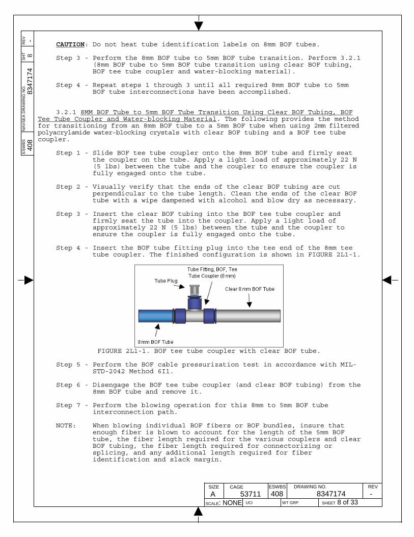
Step 4 - Insert the BOF tube fitting plug into the tee end of the 8mm tee
tube coupler. The finished configuration is shown in FIGURE 2L1-1.
FIGURE 2L1-1. BOF tee tube coupler with clear BOF tube.
Step 5 - Perform the BOF cable pressurization test in accordance with MIL-
STD-2042 Method 6I1. Step 6 - Disengage the BOF tee tube coupler (and clear BOF tubing) from the
8mm BOF tube and remove it. Step 7 - Perform the blowing operation for this 8mm to 5mm BOF tube
interconnection path. NOTE: When blowing individual BOF fibers or BOF bundles, insure that
enough fiber is blown to account for the length of the 5mm BOF tube, the fiber length required for the various couplers and clear BOF tubing, the fiber length required for connectorizing or splicing, and any additional length required for fiber identification and slack margin.

ES
WB
S
NA
VS
EA
DR
AW
ING
NO
. S
HT
R
EV
408
8347
174
9 -
SIZE
A CAGE
53711 ESWBS
408DRAWING NO.
8347174 REV
-SCALE: NONE UCI WT GRP SHEET 9 of 33
NOTE: Alternatively, if multiple 8mm to 5mm BOF tube interconnection paths are to be made, each of the tube transitions can be completed up to this point (steps 1-7) and then all blowing operations can be performed at one time. This method can then be resumed for each interconnection at this point.
Step 8 - Using scissors, trim back the individual BOF fibers or the BOF
bundle that exits the 8mm BOF tube to the appropriate length required, taking into account the length of the 5mm BOF tube, the fiber length required for the various couplers and clear BOF tubing, the fiber length required for connectorizing or splicing, and any additional length required for fiber identification and slack margin.
Step 9 - If individual BOF fibers were blown through the BOF cable path,
perform steps 9a-e. Otherwise, if a BOF bundle was blown, skip to Step 10.
a. If individual BOF fibers were blown, work a small amount of
sealant tape around the individual BOF fibers approximately 22mm (1 inch) from the open end of the BOF tube.
b. Place the appropriate sized tapered tube plug around the
individual BOF fibers and sealant tape (see FIGURE 2L1-2).
NOTE: The tapered tube plug should be oriented with the tapered end of the plug towards the open end of the BOF tube.
FIGURE 2L1-2. Applying the tapered tube plug onto the sealant tape and
individual BOF fibers.
c. Push the tapered tube plug (and individual BOF fibers) into the open end of the BOF tube until the plug is fully inserted into the tube (see FIGURE 2L1-3).
FIGURE 2L1-3. 1st tapered tube plug installed with individual BOF fibers.
d. The flange on the tapered tube plug should be even with the
outer diameter of the BOF tube. If necessary, trim the flange to the outer diameter of the tube using scissors or other appropriate cutting tool.
e. Skip to Step 11 to complete the transition.

ES
WB
S
NA
VS
EA
DR
AW
ING
NO
. S
HT
R
EV
408
8347
174
10
-
SIZE
A CAGE
53711 ESWBS
408DRAWING NO.
8347174 REV
-SCALE: NONE UCI WT GRP SHEET 10 of 33
Step 10 - If a BOF bundle was blown through the BOF cable path, perform
steps 10a-k. Otherwise, skip to step 11.
a. Mark the bundle jacket approximately 25mm (1 inch) from the open end of the BOF tube (see FIGURE 2L1-4).
FIGURE 2L1-4. Bundle mark.
NOTE: Do not pull slack fiber bundle out of the BOF tube while
breaking out the bundled fibers. If slack fiber bundle is accidentally pulled out of the BOF tube, re-establish the bundle to its original position (using the 25mm mark on the bundle jacket as an index) and continue the procedure.
b. Using the bundle jacket stripper, remove the exposed bundle
jacket in approximately 160mm (6 inches) lengths back to the mark.
NOTE: Once a short length of the bundle jacket has been removed, the
remaining length can be torn off the bundle by hand.
c. Optional step for 18-fiber bundles: Using the scissors, cut off approximately 100mm (4 inches) of the fibers from one 6-fiber subunit. Then cut off approximately 200mm (8 inches) from a different 6-fiber subunit.
NOTE: For 18-fiber bundles, fibers of the same color are contained in
each 6-fiber subunit. The 6th fiber color in each of the three 6-fiber subunits identifies the particular subunit. During the installation process, it is advantageous to know the 6-fiber subunit that each fiber comes from. One method to uniquely mark the fibers of each 6-fiber subunit is to make the fibers of each subunit a slightly different length.
d. Using the clear jacket stripper, remove approximately 80mm (3
inches) of the clear, inner jacket from the end of each 6-fiber subunit.
NOTE: If the clear jacket stripper does not bite into the clear,
inner jacket, position the clear jacket stripper at a 30 to 40 degree angle to increase its bite.
e. Find the ripcord from among the six fibers, in the subunit.
Ensure that it is not crossed with any of the fibers. While holding the group of fibers in one hand, pull the ripcord along the bundle with the other hand. Pull the ripcord until it reaches the mark on the bundle jacket.
NOTE: The ripcord and fibers spiral along the bundle length. Take
care to follow the spiral when pulling the ripcord.
f. Starting at the end of the fiber bundle subunit, carefully pull the group of fibers from the clear, inner jacket.
ES
WB
S
NA
VS
EA
DR
AW
ING
NO
. S
HT
R
EV
408
8347
174
11
-
SIZE
A CAGE
53711 ESWBS
408DRAWING NO.
8347174 REV
-SCALE: NONE UCI WT GRP SHEET 11 of 33
g. Using the scissors, carefully cut away the ripcord and the clear, inner jacket.
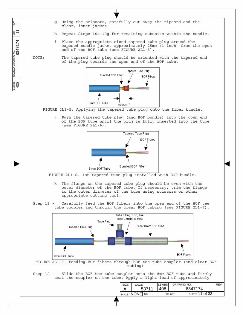
h. Repeat Steps 10e-10g for remaining subunits within the bundle.
i. Place the appropriate sized tapered tube plug around the
exposed bundle jacket approximately 25mm (1 inch) from the open end of the BOF tube (see FIGURE 2L1-5).
NOTE: The tapered tube plug should be oriented with the tapered end
of the plug towards the open end of the BOF tube.
FIGURE 2L1-5. Applying the tapered tube plug onto the fiber bundle.
j. Push the tapered tube plug (and BOF bundle) into the open end
of the BOF tube until the plug is fully inserted into the tube (see FIGURE 2L1-6).
FIGURE 2L1-6. 1st tapered tube plug installed with BOF bundle.
k. The flange on the tapered tube plug should be even with the
outer diameter of the BOF tube. If necessary, trim the flange to the outer diameter of the tube using scissors or other appropriate cutting tool.
Step 11 - Carefully feed the BOF fibers into the open end of the BOF tee
tube coupler and through the clear BOF tubing (see FIGURE 2L1-7).
FIGURE 2L1-7. Feeding BOF fibers through BOF tee tube coupler (and clear BOF
tubing). Step 12 - Slide the BOF tee tube coupler onto the 8mm BOF tube and firmly
seat the coupler on the tube. Apply a light load of approximately
ES
WB
S
NA
VS
EA
DR
AW
ING
NO
. S
HT
R
EV
408
8347
174
12
-
SIZE
A CAGE
53711 ESWBS
408DRAWING NO.
8347174 REV
-SCALE: NONE UCI WT GRP SHEET 12 of 33
22 N (5 lbs) between the tube and the coupler to ensure the coupler is fully engaged onto the tube.
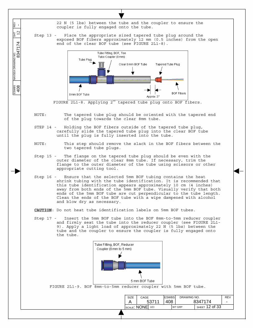
Step 13 - Place the appropriate sized tapered tube plug around the exposed BOF fibers approximately 12 mm (0.5 inches) from the open end of the clear BOF tube (see FIGURE 2L1-8).
FIGURE 2L1-8. Applying 2nd tapered tube plug onto BOF fibers.
NOTE: The tapered tube plug should be oriented with the tapered end of the plug towards the clear 8mm tube.
STEP 14 - Holding the BOF fibers outside of the tapered tube plug,
carefully slide the tapered tube plug into the clear BOF tube until the plug is fully inserted into the tube.
NOTE: This step should remove the slack in the BOF fibers between the
two tapered tube plugs.
Step 15 - The flange on the tapered tube plug should be even with the outer diameter of the clear 8mm tube. If necessary, trim the flange to the outer diameter of the tube using scissors or other appropriate cutting tool.
Step 16 - Ensure that the selected 5mm BOF tubing contains the heat
shrink tubing with the tube identification. It is recommended that this tube identification appears approximately 10 cm (4 inches) away from both ends of the 5mm BOF tube. Visually verify that both ends of the 5mm BOF tube are cut perpendicular to the tube length. Clean the ends of the BOF tube with a wipe dampened with alcohol and blow dry as necessary.
CAUTION: Do not heat tube identification labels on 5mm BOF tubes. Step 17 - Insert the 5mm BOF tube into the BOF 8mm-to-5mm reducer coupler
and firmly seat the tube into the reducer coupler (see FIGURE 2L1-9). Apply a light load of approximately 22 N (5 lbs) between the tube and the coupler to ensure the coupler is fully engaged onto the tube.
FIGURE 2L1-9. BOF 8mm-to-5mm reducer coupler with 5mm BOF tube.

ES
WB
S
NA
VS
EA
DR
AW
ING
NO
. S
HT
R
EV
408
8347
174
13
-
SIZE
A CAGE
53711 ESWBS
408DRAWING NO.
8347174 REV
-SCALE: NONE UCI WT GRP SHEET 13 of 33
Step 18 - Carefully feed the BOF fibers into the open end of the BOF 8mm-
to-5mm reducer coupler and through the 5mm BOF tubing (see FIGURE 2L1-10).
FIGURE 2L1-10. Feeding the BOF fibers into the BOF 8mm-to-5mm reducer
coupler (with 5mm BOF tube). Step 19 - Slide the BOF 8mm-to-5mm reducer coupler onto the clear BOF
tube and firmly seat the coupler on the tube (see FIGURE 2L1-11). Apply a light load of approximately 22 N (5 lbs) between the tube and the coupler to ensure the coupler is fully engaged onto the tube.
FIGURE 2L1-11. 8mm BOF tube to 5mm BOF tube transition.
Step 20 - Remove the BOF tube fitting plug from the BOF tee tube coupler
and set aside. Step 21 - Insert a spare piece of clear BOF tubing into the tee end of
the BOF tee tube coupler opening. Step 22 - Open the package containing the 2mm filtered polyacrylamide
crystals (minimum of .5 grams) and pour the contents into the spare piece of clear BOF tubing, through the BOF tee tube coupler, and into the clear BOF tubing and around the BOF fibers.
NOTE: If the polyacrylamide crystals do not free fall, tap on the BOF
tee tube coupler with finger, as necessary.
Step 23 - Remove the spare piece of clear BOF tubing and replace the BOF tube fitting plug into the tee end of the BOF tee tube coupler (see FIGURE 2L1-12).

ES
WB
S
NA
VS
EA
DR
AW
ING
NO
. S
HT
R
EV
408
8347
174
14
-
SIZE
A CAGE
53711 ESWBS
408DRAWING NO.
8347174 REV
-SCALE: NONE UCI WT GRP SHEET 14 of 33
FIGURE 2L1-12. 8mm BOF tube to 5mm BOF tube transition (with polyacrylamide
crystals).
NOTE: This completes the method for transitioning from an 8mm BOF tube to a 5mm BOF tube.

ES
WB
S
NA
VS
EA
DR
AW
ING
NO
. S
HT
R
EV
408
8347
174
15
-
SIZE
A CAGE
53711 ESWBS
408DRAWING NO.
8347174 REV
-SCALE: NONE UCI WT GRP SHEET 15 of 33
METHOD 2M1
5MM BOF TUBE ATTACHMENT TO SPLICE TRAYS
1. SCOPE. 1.1 Scope. This method describes the procedure for attaching a 5mm Blown
Optical Fiber (BOF) tube to a 7-inch (MIL-DTL-24728/8-51) splice tray. This method uses a brass sleeve inserted into the 5mm BOF tube which allows up to three 5mm BOF tubes to be attached to a single side of the splice tray.
1.2 While it might be possible to blow BOF fiber to a splice tray, it is
assumed that the BOF fibers will be hand fed through the 5mm tube, based upon the procedures in NAVSEA Drawing 8347174 Method 2L1.
2. REQUIRED EQUIPMENT AND MATERIALS. 2.1 The equipment and materials in Table 2M1-I shall be used to perform this
procedure.
TABLE 2M1-I. Equipment and materials.
Description Quantity
Safety glasses
1
Ruler
1
Utility knife or scissors
1
Tube cutter
1
Tie wraps, 4-inch self-clinching straps (SAE AS 23190 or equal)
As required
7-inch splice tray (MIL-DTL-24728/8-51 or equal)
As required
Brass sleeve (KITCO P/N 0731-1136 or equal)
As required
5mm tapered tube plug (Connective Solutions P/N TTP-1 or equal)
As required
8mm/5mm duct coupling tool (KITCO P/N 0745-2280 or equal)
1
Alcohol bottle with alcohol/2-propanol
1
Wipes (NAVSEA DWG 6872811-18 or equal)
As required
Canned air (NAVSEA DWG 6872811-17 or equal)
As required

ES
WB
S
NA
VS
EA
DR
AW
ING
NO
. S
HT
R
EV
408
8347
174
16
-
SIZE
A CAGE
53711 ESWBS
408DRAWING NO.
8347174 REV
-SCALE: NONE UCI WT GRP SHEET 16 of 33
3. PROCEDURES.
3.1 Safety summary. The following safety precautions shall be observed: a. Observe warnings and cautions on equipment and materials. b. Safety glasses shall be worn at all times when handling bare fibers. c. Do not touch the ends of bare fiber. Wash hands thoroughly after
handling bare fibers. d. When visually inspecting an optical fiber, never stare into the end of a
fiber connected to a laser source or LED. e. Never look into the end of a BOF tube. Always wear approved safety
glasses when handling BOF tubes that may be connected to a pressure source.
3.2 Procedure. The following provides the method for attaching a 5mm BOF
tube to a 7-inch (MIL-DTL-24728/8-51) splice tray. This method uses a brass sleeve inserted into the 5mm BOF tube. This method allows up to three 5mm BOF tubes to be attached to a single side of the splice tray.
NOTE: Keep BOF tube couplers and the ends of BOF tubes clean and free of
contaminants. NOTE: BOF tube couplers may be cleaned using distilled water and blown
dry with air. Do not clean or soak BOF tube couplers in alcohol or other cleaning agents. BOF tube couplers can be permanently damaged by exposure to alcohol and cleaning agents.
NOTE: Previously used BOF tube couplers may not adequately seal BOF
tubes. When installing BOF cabling, always use new BOF tube couplers.
CAUTION: Disengaging utilized BOF tube couplers may damage/break the
optical fibers contained within the BOF tubes.
Step 1 - If the 5mm BOF tube, that is to be connected to a splice tray, has transitioned from an 8mm BOF tube, insure that the transition from the 8mm BOF tube to the 5mm BOF tube is in accordance with NAVSEA Drawing 8347174 Method 2L1 (8MM BOF Tube to 5MM BOF Tube Transition Within Protective Enclosures).
NOTE: If the blowing of the BOF fibers (either individual or bundle)
occurs after the 5mm BOF tube is attached to the splice tray, then the tube transition, NAVSEA Drawing 8347174 Method 2L1, cannot be completed until this method is complete.
Step 2 - Insure that the routing, forming, and shaping procedures for the
5mm BOF tubing are performed in accordance with the methods applicable for the specific enclosure.
NOTE: When routing the 5mm BOF tube to the splice tray, the tube should
be routed to “Side B” of the splice tray (see FIGURE 2M1-1), which is typically towards the top-side of the tray holder. In the event that the splice tray is not oriented with “Side B” of the splice tray up, it may be necessary to run the 5mm BOF tube to “Side A” of the splice tray.

ES
WB
S
NA
VS
EA
DR
AW
ING
NO
. S
HT
R
EV
408
8347
174
17
-
SIZE
A CAGE
53711 ESWBS
408DRAWING NO.
8347174 REV
-SCALE: NONE UCI WT GRP SHEET 17 of 33
FIGURE 2M1-1. Fusion Splice Tray Layout.
Step 3 - Ensure that the 5mm BOF tube contains the heat shrink tubing with
the tube identification. It is recommended that this tube identification appears approximately 10 cm (4 inches) away from both ends of the 5mm BOF tube.
CAUTION: Do not heat tube identification labels on 5mm BOF tubes. Step 4 - Visually verify that the end of the 5mm BOF tube is cut
perpendicular to the tube length. If not perpendicular and the tube does not contain fiber, cut the tube perpendicular to the tube length using the tube cutter. If not perpendicular and the tube contains fiber, the 5mm tube should be disengaged from the coupler and slid down the fiber to allow cutting the tube with the tube cutter and then sliding the tube back. An alternative approach for cutting the tube, though not preferred, is to ring cut the tube, exercising great care not to damage the fibers inside. Clean the end of the BOF tube with a wipe dampened with alcohol and blow dry as necessary.
Step 5 - If the 5mm BOF tube is to be attached to the splice tray without
BOF fibers (either individual BOF fibers or the fibers from a BOF bundle), skip to Step 9.
Step 6 - If the BOF fibers (either individual BOF fibers or the fibers from
a BOF bundle) have already been blown and fed through the 5mm BOF tube (in accordance with NAVSEA Drawing 8347174 Method 2L1), skip to Step 8.
NOTE: If the 5mm BOF tube is attached to the splice tray without BOF
fibers, it may be necessary to remove the 5mm BOF tube from the splice tray at the time that BOF fibers are brought to the splice tray.
Step 7 - Perform the blowing of the BOF fibers (individual BOF fibers or
BOF bundle), complete the tube transition, and feed the fibers through the 5mm BOF tube.

ES
WB
S
NA
VS
EA
DR
AW
ING
NO
. S
HT
R
EV
408
8347
174
18
-
SIZE
A CAGE
53711 ESWBS
408DRAWING NO.
8347174 REV
-SCALE: NONE UCI WT GRP SHEET 18 of 33
A. Following the specific manufacturer’s blowing procedure,
perform the end-to-end blowing of the BOF fibers (individual BOF fibers or BOF bundle).
B. Following the blowing process, complete the 8mm BOF tube to 5mm
BOF tube transition process, NAVSEA Drawing 8347174 Method 2L1, for this BOF tube path.
NOTE: If the transition process (Drawing 8347174 Method 2L1) is not
completed prior to proceeding with this method, it may be difficult or impossible to complete without damaging the blown optical fibers.
Step 8 - Feed the BOF fibers into the non-flange side of the brass sleeve
and slide the brass sleeve down the BOF fibers towards the open end of the 5mm BOF tube (see FIGURE 2M1-2).
FIGURE 2M1-2. Inserting BOF fibers through brass sleeve.
Step 9 - Insert the brass sleeve into the 5mm BOF tube. The duct coupling
tool can be used to help insert the brass sleeve by aligning the inset side of the 5mm end of the tool over the sleeve flange. Applying equal pressure on the top side flange, press the sleeve into the tubing until the flange is flush with the BOF tube (see FIGURE 2M1-3 for the 5mm BOF tube with brass sleeve with BOF fibers and FIGURE 2M1-4 for 5mm BOF tube with brass sleeve without BOF fibers).
CAUTION: Use extreme care when performing the process of inserting the
brass sleeve into the BOF tubing with BOF fibers, as fibers can be damaged.
FIGURE 2M1-3. 5mm BOF tube and brass sleeve with BOF fibers.

ES
WB
S
NA
VS
EA
DR
AW
ING
NO
. S
HT
R
EV
408
8347
174
19
-
SIZE
A CAGE
53711 ESWBS
408DRAWING NO.
8347174 REV
-SCALE: NONE UCI WT GRP SHEET 19 of 33
FIGURE 2M1-4. 5mm BOF tube and brass sleeve without BOF fiber.
Step 10 - Installation of tapered tube plug into brass sleeve. If BOF fibers are not present in the 5mm BOF tube, skip to Step
12. Otherwise, place the appropriate sized tapered tube plug around the fibers approximately 12mm (0.5 inches) from the open end of the brass sleeve (see FIGURE 2M1-3). Carefully slide the tapered tube plug along the BOF fibers and into the brass sleeve until the plug is fully inserted into the sleeve.
NOTE: The tapered tube plug should be oriented with the tapered end of
the plug towards the 5mm BOF tube and brass sleeve. NOTE: Do not pull slack BOF fibers out of the 5mm BOF tube while
assembling the plug to BOF fibers and the BOF tube. If slack fibers are accidentally pulled out of the BOF tube, re-establish the fibers to their original position and continue the procedure.
Step 11 - The flange on the tapered tube plug should be even with the
outer diameter of the 5mm BOF tube and the flange on the brass sleeve. If necessary, trim the flange to the outer diameter of the tube and brass sleeve flange using scissors or other appropriate cutting tool.
Step 12 - Attaching the 5mm BOF tube to the right most position on Side B
of the splice tray. This is the desired location for the attaching a single 5mm BOF tube to a splice tray.
NOTE: FIGURE 2M1-5 identifies the mounting positions and retention
slots for the Side B entry point of the splice tray.
FIGURE 2M1-5. Mounting positions and retention slot identification.
a. Place the 5mm BOF tube down on the splice tray in the right most position on Side B. Ensure that the flange end of the brass sleeve is located above the upper retention slots (see FIGURE 2M1-6A).
ES
WB
S
NA
VS
EA
DR
AW
ING
NO
. S
HT
R
EV
408
8347
174
20
-
SIZE
A CAGE
53711 ESWBS
408DRAWING NO.
8347174 REV
-SCALE: NONE UCI WT GRP SHEET 20 of 33
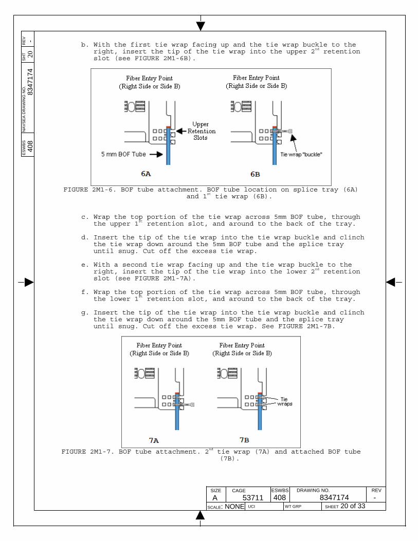
b. With the first tie wrap facing up and the tie wrap buckle to the
right, insert the tip of the tie wrap into the upper 2nd retention slot (see FIGURE 2M1-6B).
FIGURE 2M1-6. BOF tube attachment. BOF tube location on splice tray (6A)
and 1st tie wrap (6B). c. Wrap the top portion of the tie wrap across 5mm BOF tube, through
the upper 1st retention slot, and around to the back of the tray. d. Insert the tip of the tie wrap into the tie wrap buckle and clinch
the tie wrap down around the 5mm BOF tube and the splice tray until snug. Cut off the excess tie wrap.
e. With a second tie wrap facing up and the tie wrap buckle to the
right, insert the tip of the tie wrap into the lower 2nd retention slot (see FIGURE 2M1-7A).
f. Wrap the top portion of the tie wrap across 5mm BOF tube, through
the lower 1st retention slot, and around to the back of the tray. g. Insert the tip of the tie wrap into the tie wrap buckle and clinch
the tie wrap down around the 5mm BOF tube and the splice tray until snug. Cut off the excess tie wrap. See FIGURE 2M1-7B.
FIGURE 2M1-7. BOF tube attachment. 2nd tie wrap (7A) and attached BOF tube
(7B).

ES
WB
S
NA
VS
EA
DR
AW
ING
NO
. S
HT
R
EV
408
8347
174
21
-
SIZE
A CAGE
53711 ESWBS
408DRAWING NO.
8347174 REV
-SCALE: NONE UCI WT GRP SHEET 21 of 33
h. If a second 5mm BOF tube is to be attached to the splice tray, proceed to Step 13. Otherwise, this method is complete.
Step 13 - Attaching the 5mm BOF tube to the center position on Side B of
the splice tray (see FIGURE 2M1-5). This is the desired location for the attaching a second 5mm BOF tube to a splice tray.
a. Place the 5mm BOF tube down on the splice tray in the center
position on Side B. Ensure that the flange end of the brass sleeve is located above the upper retention slots.
b. With the first tie wrap facing up and the tie wrap buckle to the
right, insert the tip of the tie wrap up from the bottom of the splice tray through the upper 2nd retention slot.
c. Wrap the tie wrap across the 2nd 5mm BOF tube, and insert the tip
of the tie wrap down through the 3rd upper retention slot.
d. Insert the tip of the tie wrap into the tie wrap buckle and clinch the tie wrap down around the 5mm BOF tube and the splice tray until snug. Cut off the excess tie wrap.
e. With a second tie wrap facing up and the tie wrap buckle to the
right, insert the tip of the tie wrap up from the bottom of the splice tray through the lower 2nd retention slot.
f. Wrap the tie wrap across the 2nd 5mm BOF tube, and insert the tip
of the tie wrap down through the 3rd lower retention slot. g. Insert the tip of the tie wrap into the tie wrap buckle and clinch
the tie wrap down around the 5mm BOF tube and the splice tray until snug. Cut off the excess tie wrap. See FIGURE 2M1-8.
FIGURE 2M1-8. Splice Tray with two 5mm BOF tubes.
h. If a third 5mm BOF tube is to be attached to the splice tray,
proceed to Step 14. Otherwise, this method is complete. Step 14 - Attaching the 5mm BOF tube to the left most position on Side B
of the splice tray (see FIGURE 2M1-5). This is the location for the attaching a third 5mm BOF tube to a splice tray.
a. Place the 5mm BOF tube down on the splice tray in the left most
position on Side B. Ensure that the flange end of the brass sleeve is located above the upper retention slots.

ES
WB
S
NA
VS
EA
DR
AW
ING
NO
. S
HT
R
EV
408
8347
174
22
-
SIZE
A CAGE
53711 ESWBS
408DRAWING NO.
8347174 REV
-SCALE: NONE UCI WT GRP SHEET 22 of 33
b. With the first tie wrap facing up and the tie wrap buckle to the right, insert the tip of the tie wrap up from the bottom of the splice tray through the upper 3rd retention slot.
c. Wrap the tie wrap across the 3rd 5mm BOF tube, and insert the tip
of the tie wrap down through the 4th upper retention slot.
d. Insert the tip of the tie wrap into the tie wrap buckle and clinch the tie wrap down around the 5mm BOF tube and the splice tray until snug. Cut off the excess tie wrap.
e. With a second tie wrap facing up and the tie wrap buckle to the
right, insert the tip of the tie wrap up from the bottom of the splice tray through the lower 3rd retention slot.
f. Wrap the tie wrap across the 3rd 5mm BOF tube, and insert the tip
of the tie wrap down through the 4th lower retention slot. g. Insert the tip of the tie wrap into the tie wrap buckle and clinch
the tie wrap down around the 5mm BOF tube and the splice tray until snug. Cut off the excess tie wrap. See FIGURE 2M1-9.
FIGURE 2M1-9. Splice Tray with three 5mm BOF tubes.
NOTE: This completes the method for 5mm BOF tube attachment to a 7-inch
(MIL-DTL-24728/8-51) splice tray.

ES
WB
S
NA
VS
EA
DR
AW
ING
NO
. S
HT
R
EV
408
8347
174
23
-
SIZE
A CAGE
53711 ESWBS
408DRAWING NO.
8347174 REV
-SCALE: NONE UCI WT GRP SHEET 23 of 33
METHOD 6M1
FIBER OPTIC CONNECTOR INSPECTION AND CLEANING (INBOARD ONLY)
1. SCOPE.
1.1 Scope. This method describes the procedures for manual inspection and cleaning of ferrule endfaces for both single fiber, single ferrule connectors and each terminus in a fiber optic, multi-terminus connector. The procedures described herein use hand cleaning procedures in lieu of automated cleaning devices. This method serves as a follow-up to NAVSSES Letter Ser 96315/038 (GUIDANCE DOCUMENT: APPROACHES TO CLEANING FERRULE ENDFACES, FIBER OPTIC CONNECTORS AND TERMINI), dated 13 June 2003, in which cleaning approach 2 - multiple step cleaning (i.e., inspect, swab/wipe, inspect), is expanded upon. The criteria defining a clean condition with respect to the ferrule endface is covered in section 3.2 of this method.
Automated inspection of fiber optic single fiber, single ferrule connectors
and multi-terminus connectors may be permitted if equipment and cleanliness metrics are approved by the Naval Surface Warfare Center, Dahlgren Division, Fiber Optics Section.
1.2 Testing. This method shall be used in conjunction with Method 6C1, Cable
Assembly Link Loss Test, found in MIL-STD-2042B Part 6 for testing and troubleshooting fiber optic links aboard Navy surface ships and submarines.
1.3 General Notes. This method makes several notes that have applicability
for the entire method. a) Beginning of life connectors are those connectors that have been
terminated and tested to meet MIL-STD-2042B requirements but have not been connected to any system or patch panel.
b) In-service connectors are those connectors that have been terminated and tested to meet MIL-STD-2042B requirements but have been connected to a mating connector or patch panel.
2. REQUIRED EQUIPMENT AND MATERIALS. 2.1 The equipment and materials in Table 6M1-I shall be used to perform this
procedure.
TABLE 6M1-I. Equipment and materials.
Description Quantity
Optical microscope 400X (NAVSEA DWG 6872813-28 or equal)
1, or
Video Inspection System Kit w/probe tips, w/case, w/std barrel adapter (kit includes items below) JDSU FBP-NAVY-1 (NSN: 7Z 6650-01-587-1666 or equal) 1/, 2/, 3/, 4/. Kit includes:
Video Inspection Probe, NTSC, 200/400X, 4 pin Out JDSU FBP-P52.5 inch handheld video display JDSU FBP-HD1 (NSN 6080-01-540-75150 or equal) Probe tip, for M29504/14 pin terminus (2.0 mm dia. ferrule) JDSU FBPT-MIL-1P or equal Probe tip, patch cord, for M29504/15 socket terminus (2.0 mm dia. ferrule) JDSU FBPT-MIL-1S or equal Probe tip, patch cord, for 1.25 mm dia. ferrule JDSU FBPT-U12M (NSN 5999-01-540-7508 or equal) Probe tip, patch cord, for 2.5 mm dia. ferrule JDSU FBPT-U25M (NSN 5999-01-540-7516 or equal)
1, or

ES
WB
S
NA
VS
EA
DR
AW
ING
NO
. S
HT
R
EV
408
8347
174
24
-
SIZE
A CAGE
53711 ESWBS
408DRAWING NO.
8347174 REV
-SCALE: NONE UCI WT GRP SHEET 24 of 33
Video Inspection System Kit w/probe tips, w/case, w/std barrel adapter. (Lightel ViewConn Plus VC-6200-PL or equal) 1/, 2/, 3/, 4/. Kit includes:
ViewConn Plus VC-6200 device with CleanConn CC-1 cleaner module
Spare CC-1 module CI-1100HS digital probe ViewConn 2.5 mm PC universal tip ViewConn 1.25 mm PC universal tip ViewConn 2.0 mm PC universal tip SC/PC and FC/PC probe tip LC/PC probe tip Probe Tip Box Additional tips may be needed:
Universal 2.5mm probe tip for PC type male connectors (PT2-U2.5/PC/M)
Slim 2.0mm probe tip for male LEMO SMPTE F2 and termini (PT2-U2.0/PC/M)
Tip for 2.0mm female termini (PT2-TM2.0/PC/F) Tip for ST PC type female connectors (PT2-ST/PC/F) Probe tip for 1.25mm male ELIO connectors and termini
(PT2-ELIO1.25/PC/M) Tip for 1.25mm female termini (PT2-TM1.25/PC/F)
1
Wipes (NAVSEA DWG 6872813-8 or equal)
As required
Alcohol, Isopropyl, 99% pure anhydrous (NSN 6505-00-205-6513 or equal)
As required
Dispenser, solvent 4 oz., leak proof (for alcohol) (NSN 8125-01-439-5367 or equal)
1
Alignment sleeve insertion and removal tool (ceramic termini) (NAVSEA DWG 6872813-4 or equal)
1
Cleaning swab, 1.25 mm exposed tip (NSN 6070-01-553-2267 or equal) 4/
As required
Cleaning swab, 2.5 mm exposed tip (NSN 6070-01-553-2263 or equal) 4/
As required
Cleaning swab, 2.0 mm exposed tip (NSN 6070-01-553-2262 or equal) 4/
As required
Connector cleaning tape cassette, Reel Cleaner Type (OptiPOP R or equal) 4/
As required
Replacement cleaning tape, (OptiPOP ATC-RS-01 or equal) As required 1/ Probe tips come in different configurations. Patch cord probe tips are defined as any tip inserted directly onto the ferrule of the connector or terminus. For a socket terminus, the patch cord probe tip is placed onto the surface of the connector insert cavity or socket terminus alignment sleeve. Bulkhead adapter probe tips are placed into a connector adapter (such as an ST-to-ST adapter), a test probe adapter, or the equipment interface port (such as the equipment LC connector interface port). 2/ This probe tip can be used to inspect the M28876 test probe also (M28876 test probe is used with the M28876 test probe adapter). 3/ Because the FOVIS is limited to 200X magnification, it may not provide sufficient resolution to inspect for all types of connector endface damage.

ES
WB
S
NA
VS
EA
DR
AW
ING
NO
. S
HT
R
EV
408
8347
174
25
-
SIZE
A CAGE
53711 ESWBS
408DRAWING NO.
8347174 REV
-SCALE: NONE UCI WT GRP SHEET 25 of 33
4/ If manufacturers desire to be considered to be added to this list. Please submit package to the Naval Surface Warfare Center Dahlgren Division, Fiber Optics Section.
3. PROCEDURES.
3.1 Safety summary. The following safety precautions shall be observed: a. When visually inspecting an optical fiber, never stare into the end of a
fiber connected to a laser source or LED. b. Observe warnings and cautions on equipment and materials. c. Deactivate the system or unplug both ends of cable assembly to be
inspected prior to viewing the terminus endface to avoid potential exposure to transmitted light and possible eye injury.
3.2 Fiber Optic Connector Inspection and Cleaning Process. The following
steps provide the process for inspecting fiber optic connectors and termini. NOTE: Observe all safety warnings summarized in section 3.1 of this
procedure.
Step 1 - Identify the fiber optic connector or multi-terminus connector mated pair to be inspected.
Step 2 - Disconnect the fiber optic connector or multi-terminus connector
mated pair. NOTE: Place clean dust covers or dust caps over the fiber optic ferrules
or multiple terminus connectors to prevent contamination and/or damage. See Section 3.4 for details about cleaning dust caps or dust covers.
Step 3 - Using the flowchart shown in FIGURE 6M1-1, perform the steps
required to inspect and clean the selected mated pair. NOTE: For single fiber, single ferrule connectors such as the ST, SC,
FC, and LC, follow section 3.2.1. NOTE: For multi-terminus connectors such as the M28876, follow section
3.2.2.

ES
WB
S
NA
VS
EA
DR
AW
ING
NO
. S
HT
R
EV
408
8347
174
26
-
SIZE
A CAGE
53711 ESWBS
408DRAWING NO.
8347174 REV
-SCALE: NONE UCI WT GRP SHEET 26 of 33
FIGURE 6M1-1. Inspection and Cleaning Flowchart.
ES
WB
S
NA
VS
EA
DR
AW
ING
NO
. S
HT
R
EV
408
8347
174
27
-
SIZE
A CAGE
53711 ESWBS
408DRAWING NO.
8347174 REV
-SCALE: NONE UCI WT GRP SHEET 27 of 33
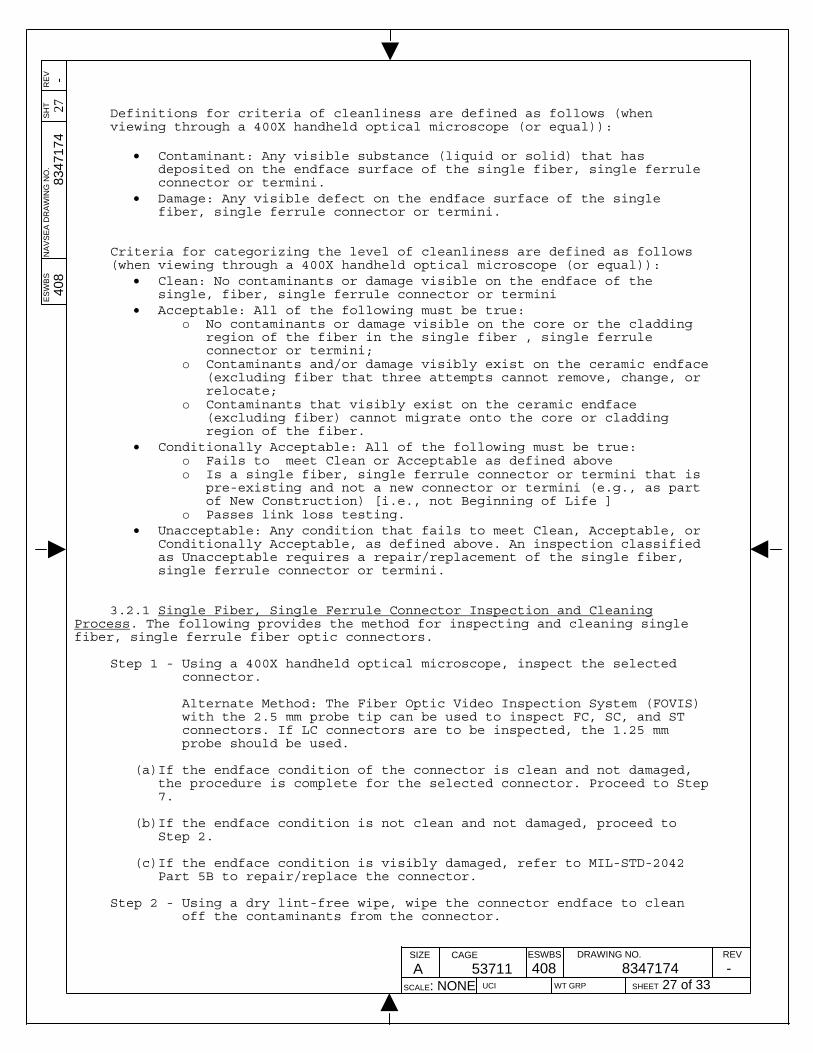
Definitions for criteria of cleanliness are defined as follows (when viewing through a 400X handheld optical microscope (or equal)):
Contaminant: Any visible substance (liquid or solid) that has deposited on the endface surface of the single fiber, single ferrule connector or termini.
Damage: Any visible defect on the endface surface of the single fiber, single ferrule connector or termini.
Criteria for categorizing the level of cleanliness are defined as follows (when viewing through a 400X handheld optical microscope (or equal)):
Clean: No contaminants or damage visible on the endface of the single, fiber, single ferrule connector or termini
Acceptable: All of the following must be true: o No contaminants or damage visible on the core or the cladding
region of the fiber in the single fiber , single ferrule connector or termini;
o Contaminants and/or damage visibly exist on the ceramic endface (excluding fiber that three attempts cannot remove, change, or relocate;
o Contaminants that visibly exist on the ceramic endface (excluding fiber) cannot migrate onto the core or cladding region of the fiber.
Conditionally Acceptable: All of the following must be true: o Fails to meet Clean or Acceptable as defined above o Is a single fiber, single ferrule connector or termini that is
pre-existing and not a new connector or termini (e.g., as part of New Construction) [i.e., not Beginning of Life ]
o Passes link loss testing. Unacceptable: Any condition that fails to meet Clean, Acceptable, or
Conditionally Acceptable, as defined above. An inspection classified as Unacceptable requires a repair/replacement of the single fiber, single ferrule connector or termini.
3.2.1 Single Fiber, Single Ferrule Connector Inspection and Cleaning
Process. The following provides the method for inspecting and cleaning single fiber, single ferrule fiber optic connectors.
Step 1 - Using a 400X handheld optical microscope, inspect the selected
connector.
Alternate Method: The Fiber Optic Video Inspection System (FOVIS) with the 2.5 mm probe tip can be used to inspect FC, SC, and ST connectors. If LC connectors are to be inspected, the 1.25 mm probe should be used.
(a)If the endface condition of the connector is clean and not damaged,
the procedure is complete for the selected connector. Proceed to Step 7.
(b)If the endface condition is not clean and not damaged, proceed to
Step 2.
(c)If the endface condition is visibly damaged, refer to MIL-STD-2042 Part 5B to repair/replace the connector.
Step 2 - Using a dry lint-free wipe, wipe the connector endface to clean
off the contaminants from the connector.

ES
WB
S
NA
VS
EA
DR
AW
ING
NO
. S
HT
R
EV
408
8347
174
28
-
SIZE
A CAGE
53711 ESWBS
408DRAWING NO.
8347174 REV
-SCALE: NONE UCI WT GRP SHEET 28 of 33
Alternate Method: Using a Reel Cleaner (or equivalent), wipe the connector endface on an unused section of the cartridge tape (NOTE: It may be necessary to advance the cartridge in order to expose an unused section of the cleaner tape). Make only one pass with the connector and only apply light pressure.
Step 3 - Using a 400X handheld optical microscope, or equivalent (see
Alternate Method for FOVIS, above), inspect the selected connector.
(a)If the endface condition of the connector is clean and not damaged,
the procedure is complete for the selected connector. Proceed to Step 7.
(b)If the endface condition is not clean and not damaged, proceed to Step 4.
(c)If the endface condition is visibly damaged, refer to MIL-STD-2042 Part 5B to repair/replace the connector.
Step 4 - Using a lint-free wipe dampened with 99% alcohol, wipe the
connector endface to clean off the contaminants from the connector.
Step 5 – Using a dry lint-free wipe, wipe the connector endface to dry the
exposed area. Alternate Method: Using a Reel Cleaner (or equivalent), wipe the
connector endface on an unused section of the cartridge tape to dry the exposed area (NOTE: It may be necessary to advance the cartridge in order to expose an unused section of the cleaner tape).
Step 6 - Using a 400X handheld optical microscope or equivalent (see
Alternate Method for FOVIS, above), inspect the selected connector.
(a)If the endface condition of the connector is clean and not damaged,
the procedure is complete for the selected connector. Proceed to Step 7.
(b)If the endface condition is not clean, repeat Steps 4 and 5.
NOTE: Steps 4 and 5 can be performed for a maximum of three attempts.
(c)If after three attempts the microscope is showing that the cleaning
process is not effective, perform the following activities:
i. Assess the connector against the Acceptable criteria found herein. If the connector is found to be acceptable, proceed to Step 7. If connector is found to be Unacceptable or Conditionally Acceptable, proceed to Step 6ii or Step 6iii, below:
ii. For beginning of life of connectors, refer to MIL-STD-2042 Part 5B to repair/replace connector.
iii. For in-service connectors, perform cable assembly link loss testing (MM and SM) and return loss testing (SM only) per MIL-STD-2042 Part 6B. If connector passes link loss testing (and return loss testing for SM only), the connector is classified as Conditionally Acceptable and can be used, but should be cataloged for eventual repair/replacement per MIL-STD-2042 Part 5B, as the availability schedule permits. If connector does not

ES
WB
S
NA
VS
EA
DR
AW
ING
NO
. S
HT
R
EV
408
8347
174
29
-
SIZE
A CAGE
53711 ESWBS
408DRAWING NO.
8347174 REV
-SCALE: NONE UCI WT GRP SHEET 29 of 33
pass the cable assembly link loss testing (and return loss testing for SM only), refer to MIL-STD-2042 Part 5B to repair/replace the connector.
NOTE: Inspect and clean other connectors in the cable assembly according
to the procedures contained herein prior to testing the cable assembly.
Step 7 – Place clean dust cap on clean connector. Refer to Section 3.4 for
the process to clean dust caps Step 8 – Repeat Steps 1-7 for the mating connector that was selected. Step 9 – Proceed to section 3.3 to clean the alignment sleeve of the
connector adapter. Step 10 – Remove dust caps from connectors and re-mate connectors using the
connector adapter. NOTE: Do not mate connectors until both connectors and the alignment
sleeve have been inspected and cleaned. Failure to do so will result in contamination of the already-cleaned connectors/alignment sleeves.
3.2.2 Multi-Terminus Connector Inspection and Cleaning Process. The following provides the method for inspecting and cleaning termini while they remain installed (i.e., pinned) within their respective multi-terminus connectors.
FIGURE 6M1-2. Fiber Optic Video Inspection System. Step 1 - Using an approved Fiber Optic Video Inspection System (FOVIS) as
shown in FIGURE 6M1-2, inspect the termini contained within the selected connector with the attached probe.
NOTE: When inspecting the ferrule endface, ensure the correct inspection
tip is used. NOTE: For M29504/14 termini in M28876 plugs (P designation), use the
FBPT-MIL-1P probe tip (for the JDSU FBP-NAVY-1 FOVIS) or the ViewConn 2.00 mm PC universal tip (for the Lightel ViewConn Plus VC-6200-PL FOVIS).
ES
WB
S
NA
VS
EA
DR
AW
ING
NO
. S
HT
R
EV
408
8347
174
30
-
SIZE
A CAGE
53711 ESWBS
408DRAWING NO.
8347174 REV
-SCALE: NONE UCI WT GRP SHEET 30 of 33
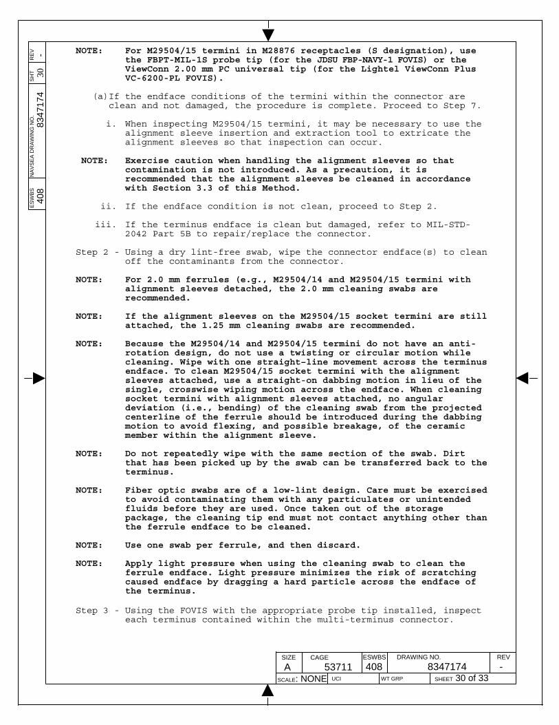
NOTE: For M29504/15 termini in M28876 receptacles (S designation), use the FBPT-MIL-1S probe tip (for the JDSU FBP-NAVY-1 FOVIS) or the ViewConn 2.00 mm PC universal tip (for the Lightel ViewConn Plus VC-6200-PL FOVIS).
(a)If the endface conditions of the termini within the connector are
clean and not damaged, the procedure is complete. Proceed to Step 7.
i. When inspecting M29504/15 termini, it may be necessary to use the alignment sleeve insertion and extraction tool to extricate the alignment sleeves so that inspection can occur.
NOTE: Exercise caution when handling the alignment sleeves so that contamination is not introduced. As a precaution, it is recommended that the alignment sleeves be cleaned in accordance with Section 3.3 of this Method.
ii. If the endface condition is not clean, proceed to Step 2.
iii. If the terminus endface is clean but damaged, refer to MIL-STD-
2042 Part 5B to repair/replace the connector. Step 2 - Using a dry lint-free swab, wipe the connector endface(s) to clean
off the contaminants from the connector. NOTE: For 2.0 mm ferrules (e.g., M29504/14 and M29504/15 termini with
alignment sleeves detached, the 2.0 mm cleaning swabs are recommended.
NOTE: If the alignment sleeves on the M29504/15 socket termini are still
attached, the 1.25 mm cleaning swabs are recommended. NOTE: Because the M29504/14 and M29504/15 termini do not have an anti-
rotation design, do not use a twisting or circular motion while cleaning. Wipe with one straight–line movement across the terminus endface. To clean M29504/15 socket termini with the alignment sleeves attached, use a straight-on dabbing motion in lieu of the single, crosswise wiping motion across the endface. When cleaning socket termini with alignment sleeves attached, no angular deviation (i.e., bending) of the cleaning swab from the projected centerline of the ferrule should be introduced during the dabbing motion to avoid flexing, and possible breakage, of the ceramic member within the alignment sleeve.
NOTE: Do not repeatedly wipe with the same section of the swab. Dirt
that has been picked up by the swab can be transferred back to the terminus.
NOTE: Fiber optic swabs are of a low-lint design. Care must be exercised
to avoid contaminating them with any particulates or unintended fluids before they are used. Once taken out of the storage package, the cleaning tip end must not contact anything other than the ferrule endface to be cleaned.
NOTE: Use one swab per ferrule, and then discard. NOTE: Apply light pressure when using the cleaning swab to clean the
ferrule endface. Light pressure minimizes the risk of scratching caused endface by dragging a hard particle across the endface of the terminus.
Step 3 - Using the FOVIS with the appropriate probe tip installed, inspect
each terminus contained within the multi-terminus connector.

ES
WB
S
NA
VS
EA
DR
AW
ING
NO
. S
HT
R
EV
408
8347
174
31
-
SIZE
A CAGE
53711 ESWBS
408DRAWING NO.
8347174 REV
-SCALE: NONE UCI WT GRP SHEET 31 of 33
(a)If the endface condition of the terminus is clean and not damaged, then continue with the inspection of the other termini within the multi-terminus connector and, when complete, proceed to Step 7.
(b)If the endface condition is still not clean, proceed to Step 4.
(c)If the endface condition is visibly damaged, refer to MIL-STD-2042
Part 5B to repair/replace the connector.
Step 4 - Using a lint-free swab dampened with 99% alcohol, wipe the connector endface to clean off the contaminants (Refer to Notes in Step 2).
Step 5 – Using a dry lint-free swab, wipe the terminus endface dry in the
alcohol-exposed region (Refer to Notes in Step 2). Step 6 - Using the FOVIS with the appropriate probe tip installed, inspect
the cleaned terminus:
(a)If the endface condition of the terminus is clean and not damaged, the procedure is complete for the selected terminus, proceed to Step 8. If a M28876 receptacle is being inspected and cleaned, proceed to Step 7.
(b)If the endface condition is not clean, repeat Steps 3 through 5.
NOTE: Steps 3 through 5 can be performed for a maximum of three attempts.
(c)If after three attempts the FOVIS is showing that the cleaning process is not effective, perform the following activities: i. Assess the terminus against the Acceptable criteria found
herein. If the terminus is found to be Acceptable, proceed to Step 7. If terminus is found to be Unacceptable or Conditionally Acceptable, proceed to Step 6ii or Step 6iii, below.
ii. For beginning of life of connectors, refer to MIL-STD-2042 Part 5B to repair/replace the terminus.
iii. For in-service connectors, perform cable assembly link loss
testing (MM and SM) and return loss testing (SM only) per MIL-STD-2042 Part 6B. If terminus passes link loss testing (and return loss testing for SM only), the terminus is classified as Conditionally Acceptable and can be used, but should be cataloged for eventual repair/replacement per MIL-STD-2042 Part 5B, as the availability schedule permits. If terminus does not pass the cable assembly link loss testing (and return loss testing for SM only), refer to MIL-STD-2042 Part 5B to repair/replace the connector.
NOTE: Inspect and clean other connectors in the cable assembly according
to the procedures contained herein prior to testing the cable assembly.
Step 7 – For M28876 receptacles only: Use the alignment sleeve insertion
and extraction tool to re-insert the alignment sleeves back onto the termini after they have been cleaned. Refer to Section 3.3 for details regarding alignment sleeve cleaning
NOTE: Exercise extreme caution when reinserting the alignment sleeves
into the connector so that contaminants are not introduced to the termini and/or the alignment sleeves. As a precaution, it is recommended that the alignment sleeves be cleaned in accordance with Section 3.3 of this Method.

ES
WB
S
NA
VS
EA
DR
AW
ING
NO
. S
HT
R
EV
408
8347
174
32
-
SIZE
A CAGE
53711 ESWBS
408DRAWING NO.
8347174 REV
-SCALE: NONE UCI WT GRP SHEET 32 of 33
Step 8 - Place clean dust cap on clean connector. Refer to Section 3.4 for details regarding dust cap cleaning.
Step 9 – Repeat Steps 1-8 for other connector that was selected. Step 10 – Remove dust caps from connectors and re-mate connectors. NOTE: Do not mate connectors until both of the connectors’ termini and
associated alignment sleeves have been inspected and cleaned. Failure to do so will result in contamination of the already-cleaned termini/ alignment sleeves.
NOTE: Prior to re-mating, observe the keying arrangements of the
connectors to properly align and the plug with the receptacle.
3.3 Fiber Optic Alignment Sleeve Cleaning Process. The following provides
the method for cleaning fiber optic alignment sleeves.
Step 1 – Using a swab dampened with 99% alcohol, insert the swab into the alignment sleeve.
NOTE: For 2.5 mm alignment sleeves, the 2.5 mm cleaning swab is
recommended. NOTE: For 2.0 mm alignment sleeves, the 2.0 mm cleaning swab is
recommended. NOTE: For 1.25 mm alignment sleeves, the 1.25 mm cleaning swab is
recommended. Step 2 – Rotate swab 10 times in a clockwise or counterclockwise direction
while moving the swab back-and-forth within the sleeve.
NOTE: Once a direction is chosen in which to rotate the swab inside the alignment sleeve, maintain the same direction of rotation until the swab has been rotated 10 times.
(a)Inspect the inside of the alignment sleeve for debris that could
contaminate the ferrule endfaces when mated and re-clean as necessary.
Step 3 – Discard the cleaning swab after use to prevent cross contaminating
other alignment sleeves. Step 4 – Inspect the alignment sleeve for damage that could cause
misalignment of the connectors.
(a)Replace connector adapter (for single terminus connectors) or alignment sleeve (for multi-terminus connectors) if damage is observed.
Step 5 – Repeat Steps 1-4 for remaining alignment sleeves.
3.4 Fiber optic dust cap cleaning process. The following provides the method for cleaning fiber optic dust caps. For single terminus connector and adapter dust caps, follow section 3.4.1. For multi-terminus connector dust caps, follow section 3.4.2.
3.4.1 Single ferrule connector and adapter dust cap cleaning process. Step 1 - Identify the dust caps that need to be cleaned.

ES
WB
S
NA
VS
EA
DR
AW
ING
NO
. S
HT
R
EV
408
8347
174
33
-
SIZE
A CAGE
53711 ESWBS
408DRAWING NO.
8347174 REV
-SCALE: NONE UCI WT GRP SHEET 33 of 33
Step 2 - Using a swab a dampened with 99% alcohol, insert the swab into the dust cap.
NOTE: For 2.5 mm ferrule dust caps, such as those used with FCs, SCs,
and STs, the 2.5 mm cleaning swab is recommended. NOTE: For 1.25 mm ferrule dust caps, such as those used with LCs, the
1.25 mm cleaning swab is recommended.
(a)Rotate swab 5 times in a clockwise or counterclockwise direction while moving the swab back-and-forth within the cap.
NOTE: Once a direction is chosen in which to rotate the swab inside
the alignment sleeve, maintain the same direction of rotation until the swab has been rotated 10 times.
Step 3 - Using a dry swab, insert the swab into the dust cap to remove
excess alcohol.
(a)Inspect the inside of the dust cap for debris that could contaminate the ferrule endface when mated and re-clean as necessary.
Step 4 - Place dust cap on dry wipe with the open-endface down to prevent
the ingress of contaminants Step 5 - Repeat Steps 1-4 for remaining dust caps.
3.4.2 Multi-Terminus connector dust cap cleaning process. Step 1 - Identify the dust caps that need to be cleaned. Step 2 - Using a wipe a dampened with 99% alcohol, wipe the region of the
dust cap that covers the connector. Step 3 - Using a dry wipe, wipe the region of the dust cap that covers the
connector to remove excess moisture.
(a)Inspect the inside of the dust cap for debris that could contaminate the termini endfaces when attached and re-clean as necessary.
Step 4 - Place dust cap on dry wipe with the open-endface down to prevent
the ingress of contaminants. Step 5 - Repeat Steps 1-4 for remaining dust caps.