revision 1 to 10810-03660-ar-001, 'preliminary design
TRANSCRIPT
AECL E/K.lL Analysis Report PRELIMINARY DESIGN ASSIST PSA LEVEL l- SELECTED FULL POWER EVENT TREES ACR-700 1081 O-03660-AR-001
Revision 1
Iliescu Petre Ozdemir Abdullah Nainer Alina C. .
Menon Usha
Reviewed bv V&if@ par ’
Blahnik Charles Shapiro Hymie
Jaitly Raj Bonechi Massimo
2004/01/28 Controlled Licensing
@Atomic Energy of Canada Limited
2251 Speakman Drive Mississauga, Ontario Canada L5K 182
2004/01/28 Contr616 Licensing
Ohergie Atomique du Canada Limitke
2251 rue Speakman Mississauga (Ontario) Canada L5K 1 B2
10810-03660-AR-001 2004/01/28
Analysis Report
Preliminary Design Assist PSA Level 1 - Selected Full Power Event Trees
ACR-700
10810-03660-AR-001 Revision 1
2004 January
CONTROLLED - Licensing This document and the information contained in it is made available for licensing review. All rights reserved by Atomic Energy of Canada Limited. No part of this document may be reproduced or transmitted in any form or by any means, including photocopying and recording, without the written permission of the copyright holder, application for which should be addressed to Atomic Energy of Canada Limited. Such written permission must also be obtained before any part of this document is stored in a retrieval system of any nature.
Janvier 2004
CONTRÔLÉ - Permis Le présent document et l’information qu’il contient sont disponibles pour examen en vue de l’obtention des permis. Tous droits réservés par Énergie atomique du Canada limitée. Il est interdit de reproduire ou de transmettre, par quelque procédé que ce soit, y compris de photocopier ou d’enregistrer, toute partie du présent document, sans une autorisation écrite du propriétaire du copyright obtenue auprès d’Énergie atomique du Canada limitée. De plus, on doit obtenir une telle autorisation avant qu’une partie du présent document ne soit intégrée dans un système de recherche documentaire de quelque nature que ce soit.
� Atomic Energy of Canada Limited
© Énergie atomique du Canada limitée
2251 Speakman Drive Mississauga, Ontario Canada L5K 1B2
2251, rue Speakman Mississauga (Ontario) Canada L5K 1B2
Release and Liste des documents Revision History et des révisions 0939B Rev. 13
Document Details / Détails sur le document
Title Titre
Total no. of pages Nbre total de pages
Preliminary Design Assist PSA Level 1 - Selected Full Power Event Trees
CONTROLLED - Licensing / CONTRÔLÉ - Permis Release and Revision History / Liste des documents et des révisions
Release Document
Revision Révision
Purpose of Release; Details of Rev./Amendement Objet du document; détails des rév. ou des modif.
Prepared by Rédigé par
Reviewed by Examiné par
Approved by Approuvé par
No./No Date No./No Date
DCS/RMS Input / Données SCD ou SGD
Rel. Proj. Proj. conn.
Project Projet
SI
Section
Serial Série
Sheet Feuille No. N
o
Of De
Unit No.(s) Tranche no
10810 03660 AR 001 1 1 dsfpdfrg 10810-03660-AR-001 2004/01/28
1 0 2003/12/05 Issued as “Approved for Use”.
U. Menon A. Nainer A. Ozdemir P. Iliescu
H. Shapiro R. Jaitly M. Bonechi
2 1 2004/01/28 Issued as “Approved for Use”. Editorial changes. Changed to “Controlled - Licensing”. This document replaces 108-03660-220-001.
U. Menon A. Nainer A. Ozdemir P. Iliescu
H. Shapiro C. Blahnik
R. Jaitly M. Bonechi
CONTROLLED - Licensing 10810-03660-AR-001 Page i Rev. 1
10810-03660-AR-001 2004/01/28
ACRONYMS IN TEXT
ACND Auxiliary Condensate (system)
ACR Advanced CANDU Reactor
AFW Auxiliary Feed Water (subsystem)
AFW-IS Auxiliary Feed Water – Isolation (failure)
ASDV Atmospheric Steam Discharge Valve
ADW Auto De-pressurization Water (system)
AV-DGS<3 Less Than Three Diesel Generator Sets are Available
BPCC Boiler Pressure Control Cooldown (subsystem)
CC Crash Cool-down (of steam generators)
CLPRV No LOCA via D2O Storage Tank (LRVs fail to reclose)
CLPS Consequential LOCA via pump seals
CND Condensate (system)
CSDV Condenser Steam Dump Valve
D1SW Division 1 Service Water
DECC Dormant Emergency (Core) Cooling (same as ECI)
DG Diesel Generator
DG-AV=1 1 Diesel Generator Set Available
ECC Emergency Core Cooling
ECI Emergency Coolant Injection (system)
EFW Emergency Feed Water (supply from RWS to SG)
ET Event Tree
FBIO Feeder Break
FSB Feeder Stagnation Break
FW Feed Water systems (includes MFW and AFW subsystem)
FWBA Asymmetric feed water line break downstream of the SG check valve
FWBS Symmetric feed water line break upstream of the feed water LCVs
HEP Human Error Probability
HT Heat Transport
HTS Heat Transport System (same as RCS)
CONTROLLED - Licensing 10810-03660-AR-001 Page ii Rev. 1
10810-03660-AR-001 2004/01/28
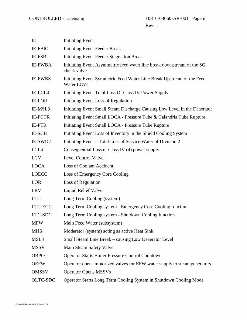
IE Initiating Event
IE-FBIO Initiating Event Feeder Break
IE-FSB Initiating Event Feeder Stagnation Break
IE-FWBA Initiating Event Asymmetric feed water line break downstream of the SG check valve
IE-FWBS Initiating Event Symmetric Feed Water Line Break Upstream of the Feed Water LCVs
IE-LCL4 Initiating Event Total Loss Of Class IV Power Supply
IE-LOR Initiating Event Loss of Regulation
IE-MSL3 Initiating Event Small Steam Discharge Causing Low Level in the Deaerator
IE-PCTR Initiating Event Small LOCA - Pressure Tube & Calandria Tube Rupture
IE-PTR Initiating Event Small LOCA - Pressure Tube Rupture
IE-SCB Initiating Event Loss of Inventory in the Shield Cooling System
IE-SWD2 Initiating Event – Total Loss of Service Water of Division 2
LCL4 Consequential Loss of Class IV (4) power supply
LCV Level Control Valve
LOCA Loss of Coolant Accident
LOECC Loss of Emergency Core Cooling
LOR Loss of Regulation
LRV Liquid Relief Valve
LTC Long Term Cooling (system)
LTC-ECC Long Term Cooling system - Emergency Core Cooling function
LTC-SDC Long Term Cooling system - Shutdown Cooling function
MFW Main Feed Water (subsystem)
MHS Moderator (system) acting as active Heat Sink
MSL3 Small Steam Line Break – causing Low Deaerator Level
MSSV Main Steam Safety Valve
OBPCC Operator Starts Boiler Pressure Control Cooldown
OEFW Operator opens motorized valves for EFW water supply to steam generators
OMSSV Operator Opens MSSVs
OLTC-SDC Operator Starts Long Term Cooling System in Shutdown Cooling Mode
CONTROLLED - Licensing 10810-03660-AR-001 Page iii Rev. 1
10810-03660-AR-001 2004/01/28
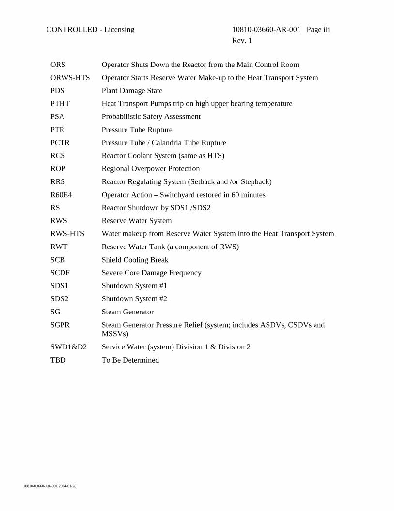
ORS Operator Shuts Down the Reactor from the Main Control Room
ORWS-HTS Operator Starts Reserve Water Make-up to the Heat Transport System
PDS Plant Damage State
PTHT Heat Transport Pumps trip on high upper bearing temperature
PSA Probabilistic Safety Assessment
PTR Pressure Tube Rupture
PCTR Pressure Tube / Calandria Tube Rupture
RCS Reactor Coolant System (same as HTS)
ROP Regional Overpower Protection
RRS Reactor Regulating System (Setback and /or Stepback)
R60E4 Operator Action – Switchyard restored in 60 minutes
RS Reactor Shutdown by SDS1 /SDS2
RWS Reserve Water System
RWS-HTS Water makeup from Reserve Water System into the Heat Transport System
RWT Reserve Water Tank (a component of RWS)
SCB Shield Cooling Break
SCDF Severe Core Damage Frequency
SDS1 Shutdown System #1
SDS2 Shutdown System #2
SG Steam Generator
SGPR Steam Generator Pressure Relief (system; includes ASDVs, CSDVs and MSSVs)
SWD1&D2 Service Water (system) Division 1 & Division 2
TBD To Be Determined
CONTROLLED - Licensing 10810-03660-AR-001 Page iv Rev. 1
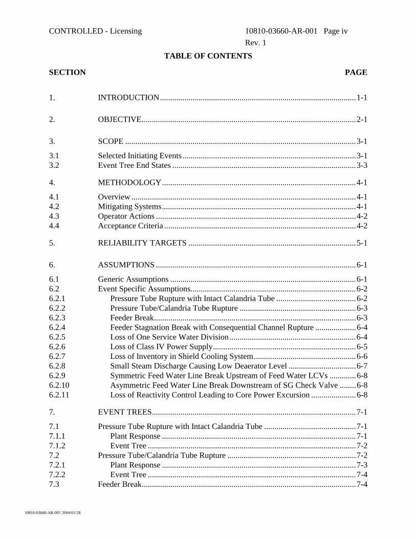
TABLE OF CONTENTS
SECTION PAGE
10810-03660-AR-001 2004/01/28
1. INTRODUCTION................................................................................................1-1
2. OBJECTIVE.........................................................................................................2-1
3. SCOPE .................................................................................................................3-1
3.1 Selected Initiating Events.....................................................................................3-1 3.2 Event Tree End States ..........................................................................................3-3
4. METHODOLOGY...............................................................................................4-1
4.1 Overview ..............................................................................................................4-1 4.2 Mitigating Systems...............................................................................................4-1 4.3 Operator Actions ..................................................................................................4-2 4.4 Acceptance Criteria ..............................................................................................4-2
5. RELIABILITY TARGETS ..................................................................................5-1
6. ASSUMPTIONS ..................................................................................................6-1
6.1 Generic Assumptions ...........................................................................................6-1 6.2 Event Specific Assumptions.................................................................................6-2 6.2.1 Pressure Tube Rupture with Intact Calandria Tube .......................................6-2 6.2.2 Pressure Tube/Calandria Tube Rupture .........................................................6-3 6.2.3 Feeder Break...................................................................................................6-3 6.2.4 Feeder Stagnation Break with Consequential Channel Rupture ....................6-4 6.2.5 Loss of One Service Water Division..............................................................6-4 6.2.6 Loss of Class IV Power Supply......................................................................6-5 6.2.7 Loss of Inventory in Shield Cooling System..................................................6-6 6.2.8 Small Steam Discharge Causing Low Deaerator Level .................................6-7 6.2.9 Symmetric Feed Water Line Break Upstream of Feed Water LCVs .............6-8 6.2.10 Asymmetric Feed Water Line Break Downstream of SG Check Valve ........6-8 6.2.11 Loss of Reactivity Control Leading to Core Power Excursion ......................6-8
7. EVENT TREES....................................................................................................7-1
7.1 Pressure Tube Rupture with Intact Calandria Tube .............................................7-1 7.1.1 Plant Response ...............................................................................................7-1 7.1.2 Event Tree ......................................................................................................7-2 7.2 Pressure Tube/Calandria Tube Rupture ...............................................................7-2 7.2.1 Plant Response ...............................................................................................7-3 7.2.2 Event Tree ......................................................................................................7-4 7.3 Feeder Break.........................................................................................................7-4
CONTROLLED - Licensing 10810-03660-AR-001 Page v Rev. 1
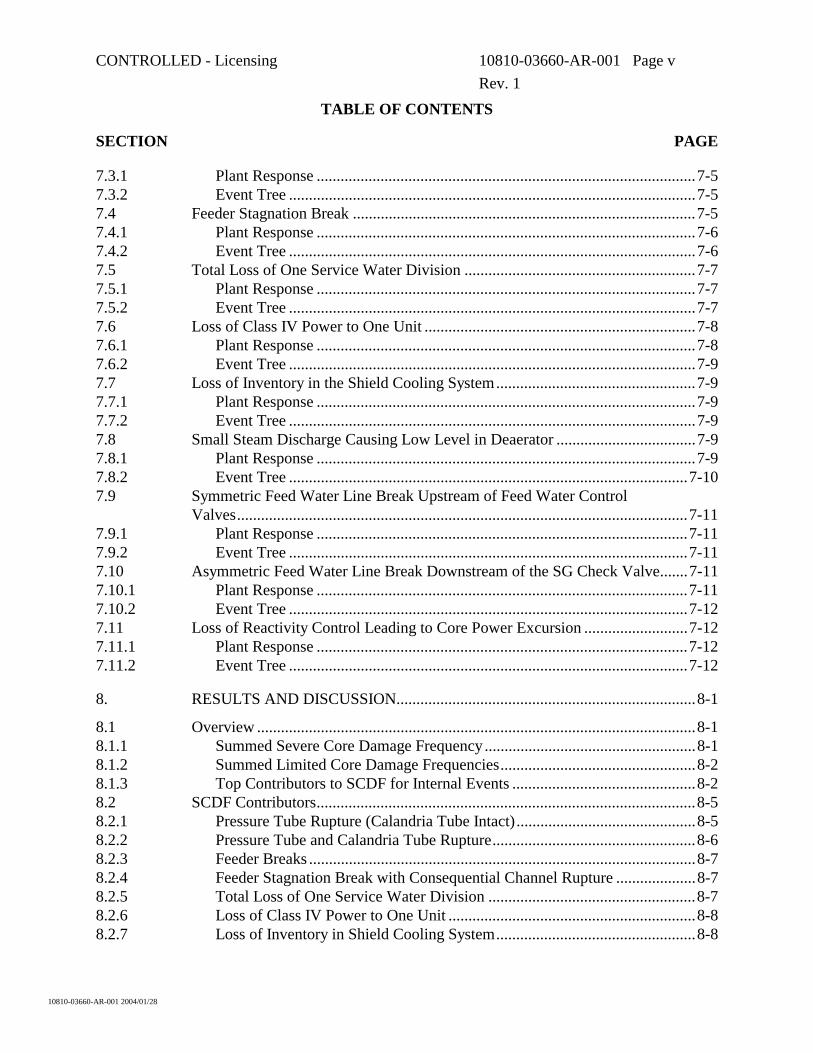
TABLE OF CONTENTS
SECTION PAGE
10810-03660-AR-001 2004/01/28
7.3.1 Plant Response ...............................................................................................7-5 7.3.2 Event Tree ......................................................................................................7-5 7.4 Feeder Stagnation Break ......................................................................................7-5 7.4.1 Plant Response ...............................................................................................7-6 7.4.2 Event Tree ......................................................................................................7-6 7.5 Total Loss of One Service Water Division ..........................................................7-7 7.5.1 Plant Response ...............................................................................................7-7 7.5.2 Event Tree ......................................................................................................7-7 7.6 Loss of Class IV Power to One Unit ....................................................................7-8 7.6.1 Plant Response ...............................................................................................7-8 7.6.2 Event Tree ......................................................................................................7-9 7.7 Loss of Inventory in the Shield Cooling System..................................................7-9 7.7.1 Plant Response ...............................................................................................7-9 7.7.2 Event Tree ......................................................................................................7-9 7.8 Small Steam Discharge Causing Low Level in Deaerator ...................................7-9 7.8.1 Plant Response ...............................................................................................7-9 7.8.2 Event Tree ....................................................................................................7-10 7.9 Symmetric Feed Water Line Break Upstream of Feed Water Control
Valves.................................................................................................................7-11 7.9.1 Plant Response .............................................................................................7-11 7.9.2 Event Tree ....................................................................................................7-11 7.10 Asymmetric Feed Water Line Break Downstream of the SG Check Valve.......7-11 7.10.1 Plant Response .............................................................................................7-11 7.10.2 Event Tree ....................................................................................................7-12 7.11 Loss of Reactivity Control Leading to Core Power Excursion ..........................7-12 7.11.1 Plant Response .............................................................................................7-12 7.11.2 Event Tree ....................................................................................................7-12
8. RESULTS AND DISCUSSION...........................................................................8-1
8.1 Overview ..............................................................................................................8-1 8.1.1 Summed Severe Core Damage Frequency .....................................................8-1 8.1.2 Summed Limited Core Damage Frequencies.................................................8-2 8.1.3 Top Contributors to SCDF for Internal Events ..............................................8-2 8.2 SCDF Contributors...............................................................................................8-5 8.2.1 Pressure Tube Rupture (Calandria Tube Intact).............................................8-5 8.2.2 Pressure Tube and Calandria Tube Rupture...................................................8-6 8.2.3 Feeder Breaks .................................................................................................8-7 8.2.4 Feeder Stagnation Break with Consequential Channel Rupture ....................8-7 8.2.5 Total Loss of One Service Water Division ....................................................8-7 8.2.6 Loss of Class IV Power to One Unit ..............................................................8-8 8.2.7 Loss of Inventory in Shield Cooling System..................................................8-8
CONTROLLED - Licensing 10810-03660-AR-001 Page vi Rev. 1
TABLE OF CONTENTS
SECTION PAGE
10810-03660-AR-001 2004/01/28
8.2.8 Small Steam Discharge Causing Low Level in Deaerator .............................8-8 8.2.9 Symmetric FW Line Break Upstream of FW Control Valves........................8-8 8.2.10 Asymmetric FW Line Break Downstream of Steam Generator Check
Valve ..............................................................................................................8-9 8.2.11 Loss of Reactivity Control Leading to Core Power Excursion ......................8-9 8.3 Role of Reserve Water System.............................................................................8-9 8.4 Key PSA Assumptions .......................................................................................8-10
9. CONCLUSIONS..................................................................................................9-1
10. REFERENCES...................................................................................................10-1
TABLES
Table 3-1 Selected Initiating Events.....................................................................................3-1
Table 3-2 Plant Damage States.............................................................................................3-3
Table 4-1 Human Error Probabilities Associated to Operator Action Times.......................4-2
Table 5-1 System Reliability /Unavailability Targets (dependent on DG availability)........5-2
Table 5-2 System Reliability /Unavailability Targets (all DGs assumed available) ............5-3
Table 8-1 Summed Frequency of Plant Damage States........................................................8-1
Table 8-2 Significant Contributors to Summed SCDF.........................................................8-3
APPENDICES
Appendix A Event Tree for Pressure Tube Rupture ................................................................A-1
Appendix B Event Tree for Pressure Tube and Calandria Tube Rupture................................ B-1
Appendix C Event Tree for Feeder Break ............................................................................... C-1
Appendix D Event Tree for Feeder Stagnation Break .............................................................D-1
Appendix E Event Tree for Total Loss of One Service Water Division ................................. E-1
CONTROLLED - Licensing 10810-03660-AR-001 Page vii Rev. 1
TABLE OF CONTENTS
SECTION PAGE
10810-03660-AR-001 2004/01/28
Appendix F Event Tree for Loss of Class IV Power to One Unit ............................................F-1
Appendix G Event Tree for Loss of Inventory in Shield Cooling System...............................G-1
Appendix H Event Tree for Small Steam Line Break Causing Low Level in the Deaerator .............................................................................................................H-1
Appendix I Event Tree for Symmetric FW Line Break Upstream of FW Control Valves....................................................................................................................I-1
Appendix J Event Tree for Asymmetric FW Line Break Downstream of SG Check Valve .................................................................................................................... J-1
Appendix K Event Tree for Loss of Reactivity Control Leading to Core Power Excursion.............................................................................................................K-1
CONTROLLED - Licensing 10810-03660-AR-001 Page 1-1
Rev. 1
10810-03660-AR-001 2004/01/28
1. INTRODUCTION
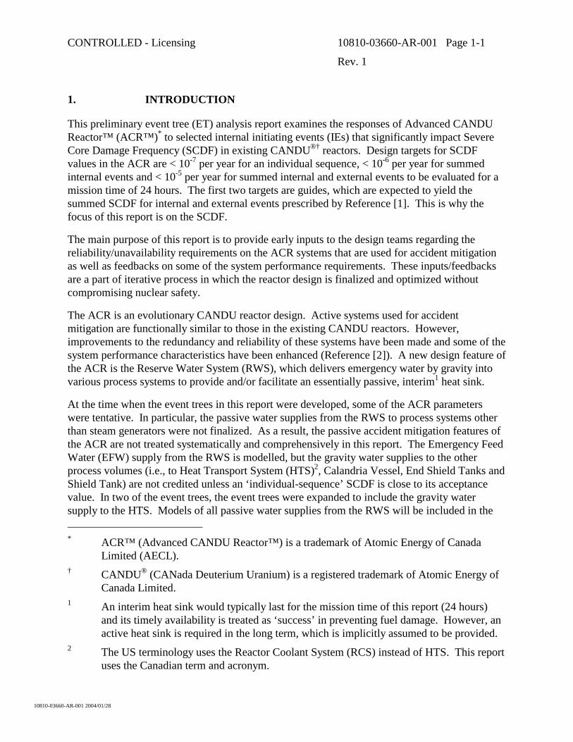
This preliminary event tree (ET) analysis report examines the responses of Advanced CANDU Reactor™ (ACR™)* to selected internal initiating events (IEs) that significantly impact Severe Core Damage Frequency (SCDF) in existing CANDU®† reactors. Design targets for SCDF values in the ACR are < 10-7 per year for an individual sequence, < 10-6 per year for summed internal events and < 10-5 per year for summed internal and external events to be evaluated for a mission time of 24 hours. The first two targets are guides, which are expected to yield the summed SCDF for internal and external events prescribed by Reference [1]. This is why the focus of this report is on the SCDF.
The main purpose of this report is to provide early inputs to the design teams regarding the reliability/unavailability requirements on the ACR systems that are used for accident mitigation as well as feedbacks on some of the system performance requirements. These inputs/feedbacks are a part of iterative process in which the reactor design is finalized and optimized without compromising nuclear safety.
The ACR is an evolutionary CANDU reactor design. Active systems used for accident mitigation are functionally similar to those in the existing CANDU reactors. However, improvements to the redundancy and reliability of these systems have been made and some of the system performance characteristics have been enhanced (Reference [2]). A new design feature of the ACR is the Reserve Water System (RWS), which delivers emergency water by gravity into various process systems to provide and/or facilitate an essentially passive, interim1 heat sink.
At the time when the event trees in this report were developed, some of the ACR parameters were tentative. In particular, the passive water supplies from the RWS to process systems other than steam generators were not finalized. As a result, the passive accident mitigation features of the ACR are not treated systematically and comprehensively in this report. The Emergency Feed Water (EFW) supply from the RWS is modelled, but the gravity water supplies to the other process volumes (i.e., to Heat Transport System (HTS)2, Calandria Vessel, End Shield Tanks and Shield Tank) are not credited unless an ‘individual-sequence’ SCDF is close to its acceptance value. In two of the event trees, the event trees were expanded to include the gravity water supply to the HTS. Models of all passive water supplies from the RWS will be included in the * ACR™ (Advanced CANDU Reactor™) is a trademark of Atomic Energy of Canada
Limited (AECL). † CANDU® (CANada Deuterium Uranium) is a registered trademark of Atomic Energy of
Canada Limited. 1 An interim heat sink would typically last for the mission time of this report (24 hours)
and its timely availability is treated as ‘success’ in preventing fuel damage. However, an active heat sink is required in the long term, which is implicitly assumed to be provided.
2 The US terminology uses the Reactor Coolant System (RCS) instead of HTS. This report uses the Canadian term and acronym.
CONTROLLED - Licensing 10810-03660-AR-001 Page 1-2
Rev. 1
10810-03660-AR-001 2004/01/28
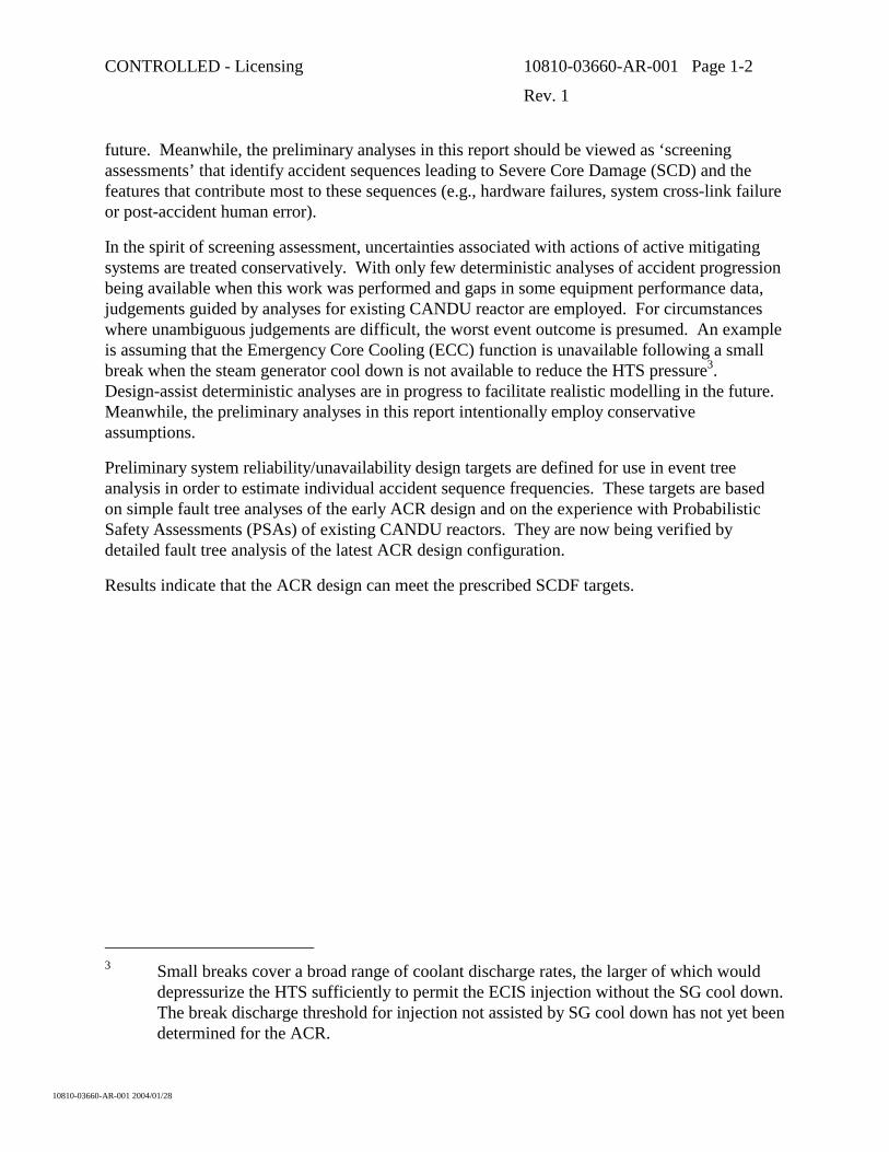
future. Meanwhile, the preliminary analyses in this report should be viewed as ‘screening assessments’ that identify accident sequences leading to Severe Core Damage (SCD) and the features that contribute most to these sequences (e.g., hardware failures, system cross-link failure or post-accident human error).
In the spirit of screening assessment, uncertainties associated with actions of active mitigating systems are treated conservatively. With only few deterministic analyses of accident progression being available when this work was performed and gaps in some equipment performance data, judgements guided by analyses for existing CANDU reactor are employed. For circumstances where unambiguous judgements are difficult, the worst event outcome is presumed. An example is assuming that the Emergency Core Cooling (ECC) function is unavailable following a small break when the steam generator cool down is not available to reduce the HTS pressure3. Design-assist deterministic analyses are in progress to facilitate realistic modelling in the future. Meanwhile, the preliminary analyses in this report intentionally employ conservative assumptions.
Preliminary system reliability/unavailability design targets are defined for use in event tree analysis in order to estimate individual accident sequence frequencies. These targets are based on simple fault tree analyses of the early ACR design and on the experience with Probabilistic Safety Assessments (PSAs) of existing CANDU reactors. They are now being verified by detailed fault tree analysis of the latest ACR design configuration.
Results indicate that the ACR design can meet the prescribed SCDF targets.
3 Small breaks cover a broad range of coolant discharge rates, the larger of which would
depressurize the HTS sufficiently to permit the ECIS injection without the SG cool down. The break discharge threshold for injection not assisted by SG cool down has not yet been determined for the ACR.
CONTROLLED - Licensing 10810-03660-AR-001 Page 2-1
Rev. 1
10810-03660-AR-001 2004/01/28
2. OBJECTIVE
The purpose of the preliminary event tree analysis is to identify which internal event sequences will likely dominate the SCDF in the ACR and which elements of the dominant sequences contribute most to the SCDF. This is a design-assist exercise performed in the early stages of design. Insights are useful for design finalization and optimization.
CONTROLLED - Licensing 10810-03660-AR-001 Page 3-1
Rev. 1
10810-03660-AR-001 2004/01/28
3. SCOPE
The scope of this work is limited to developing and analyzing event trees for selected initiating events that are judged to potentially produce high values of ‘individual-sequence’ SCDF and/or be major contributors to the ‘summed’ SCDF (Section 3.1). End states of interest pertinent to SCDF are Plant Damage States (PDS) 0 to 2 (Section 3.2), which involve significant amounts of fuel debris located beyond the HTS boundaries.
The event trees employ the standard methodology (summarized in Section 4) in conjunction with preliminary reliability targets for the mitigating systems and preliminary assumptions related to system or component performance (documented in Section 6).
Commensurate with the objective in Section 2, the analysis approach is that of a screening assessment which employs conservative assumptions and progressively expands the event tree models to identify and characterize the dominant sequences. The models initially include only the active mitigating systems and the passive EFW supply from the RWS. They are expanded as needed to represent the passive water supplies to other process systems. However, the RWS is ‘credited’ implicitly in the choice of initiating events. Certain initiating events, such as a loss of moderator cooling or a loss of shield water cooling not included in the list of Table 3-1 because extremely low SCDF values are anticipated when the passive design feature is taken into account.
3.1 Selected Initiating Events
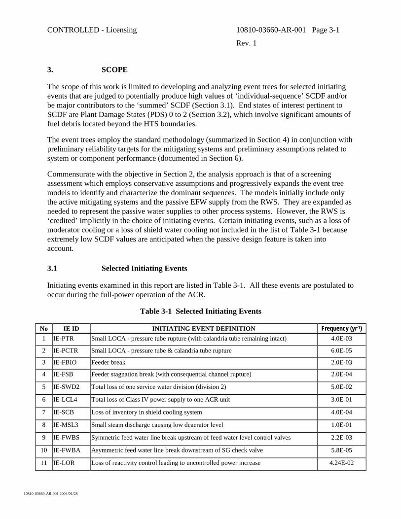
Initiating events examined in this report are listed in Table 3-1. All these events are postulated to occur during the full-power operation of the ACR.
Table 3-1 Selected Initiating Events
No IE ID INITIATING EVENT DEFINITION Frequency (yr-1) 1 IE-PTR Small LOCA - pressure tube rupture (with calandria tube remaining intact) 4.0E-03
2 IE-PCTR Small LOCA - pressure tube & calandria tube rupture 6.0E-05
3 IE-FBIO Feeder break 2.0E-03
4 IE-FSB Feeder stagnation break (with consequential channel rupture) 2.0E-04
5 IE-SWD2 Total loss of one service water division (division 2) 5.0E-02
6 IE-LCL4 Total loss of Class IV power supply to one ACR unit 3.0E-01
7 IE-SCB Loss of inventory in shield cooling system 4.0E-04
8 IE-MSL3 Small steam discharge causing low deaerator level 1.0E-01
9 IE-FWBS Symmetric feed water line break upstream of feed water level control valves 2.2E-03
10 IE-FWBA Asymmetric feed water line break downstream of SG check valve 5.8E-05
11 IE-LOR Loss of reactivity control leading to uncontrolled power increase 4.24E-02
CONTROLLED - Licensing 10810-03660-AR-001 Page 3-2
Rev. 1
10810-03660-AR-001 2004/01/28
Initiating Event frequencies are best estimate values for operating CANDU plants in Canada rounded up to the significant digit. These values are anticipated to be conservative (i.e., high) for the ACR.
Table 3-1 lists initiating events considered most significant from the viewpoint of their contribution to the summed SCDF in CANDU 6 and CANDU 9 reactor designs. They can potentially produce high values of individual-sequence SCDF by virtue of a high Initiating Event frequency and/or by virtue of unique post-accident conditions that constraint the options available for the deployment of active mitigating systems.
Initiating events 1 to 4 are small breaks, which have different characteristics in terms of accident mitigation. Pressure tube rupture, IE-PTR (No. 1), results in a leak through the channel bellows just in excess of the HTS make-up capacity that relies mostly on SG cool down for routine mitigation. Pressure tube calandria tube rupture, IE-PCTR (No. 2), is a larger in-core break that might affect the ability of the moderator to act as alternate, long-term heat sink. Feeder break, IE-FBIO (No. 3), is a prototypic small break, which occurs in a feeder of the HTS. Feeder stagnation break, IE-FSB (No. 4), is a unique small break that could interconnect both the HTS and the Calandria Vessel with the Containment, thereby potentially voiding both of these process volumes.
For the preliminary analysis, a conservatively high initiating frequency for the feeder stagnation break was assumed as 10% of any feeder break frequency. This high frequency value was deliberately selected to evaluate the robustness of the ACR mitigating system design. During the detailed PSA, a best estimate of the feeder stagnation break frequency will be calculated. For a stagnation break leading to fuel melting and channel failure, the frequency is expected to be at least an order of magnitude lower than 2E-4/yr value assumed in this report.
Initiating Event 5 (IE-SWD2), total loss of Division 2 service water, partially disrupts the gland seal and motor cooling of two HT pumps and at the same time, it also only leads to loss of half of the mitigating system heat sinks, as Division 1 service is available.
Initiating Event 6 (IE-LCL4) is a loss of normal electrical power supplies to one unit in a two-unit ACR station (presumed to have a relatively high frequency), which constrains some options available for providing active heat sinks after the accident.
Initiating Event 7 (IE-SCB) is a shield water loss, which does not immediately impact on fuel cooling, but could cause excessive thermal stresses in reactor structures if not mitigated by a timely reactor cool down.
Initiating events 8 to 10 are secondary-side breaks that disrupt the normal HTS heat sink. Small steam line discharge, IE-MSL3 (No. 8), is a high-frequency accident initiator that includes a number of operator actions for normal mitigation. Symmetric feedwater line break upstream of the feedwater level control valves in the turbine building, IE-FWBS (No. 9), could cause a consequential loss of normal electrical power supply to complicate the accident mitigation. Asymmetric feedwater line break downstream of SG check valve in the reactor building, IE-
CONTROLLED - Licensing 10810-03660-AR-001 Page 3-3
Rev. 1
10810-03660-AR-001 2004/01/28
FWBA (No. 10), is a unique break that cannot be isolated from the affected SG. The inability to isolate constrains the options that are available for accident mitigation.
Loss of regulation, Initiating Event 11 (IE-LOR), is a power excursion that would cause a power-cooling mismatch at high power and high HTS pressure if not automatically mitigated in timely manner.
3.2 Event Tree End States
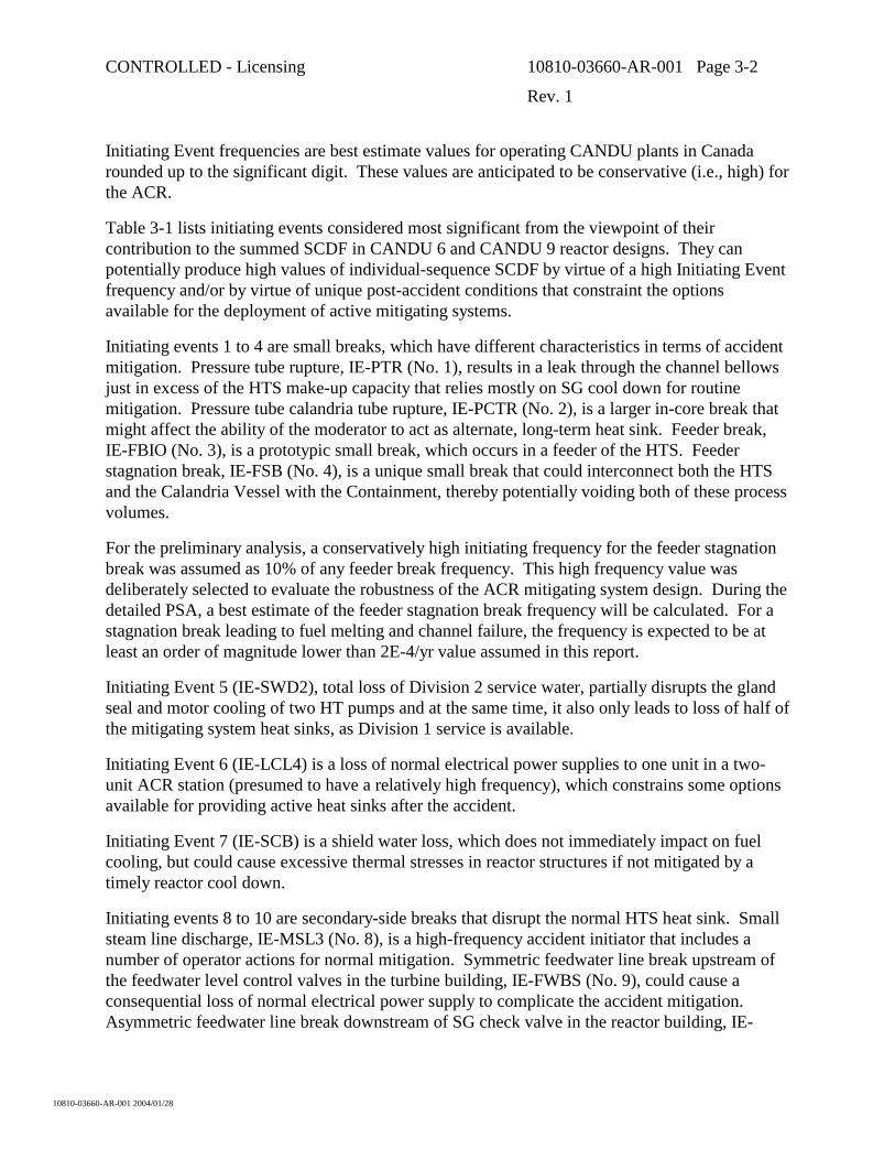
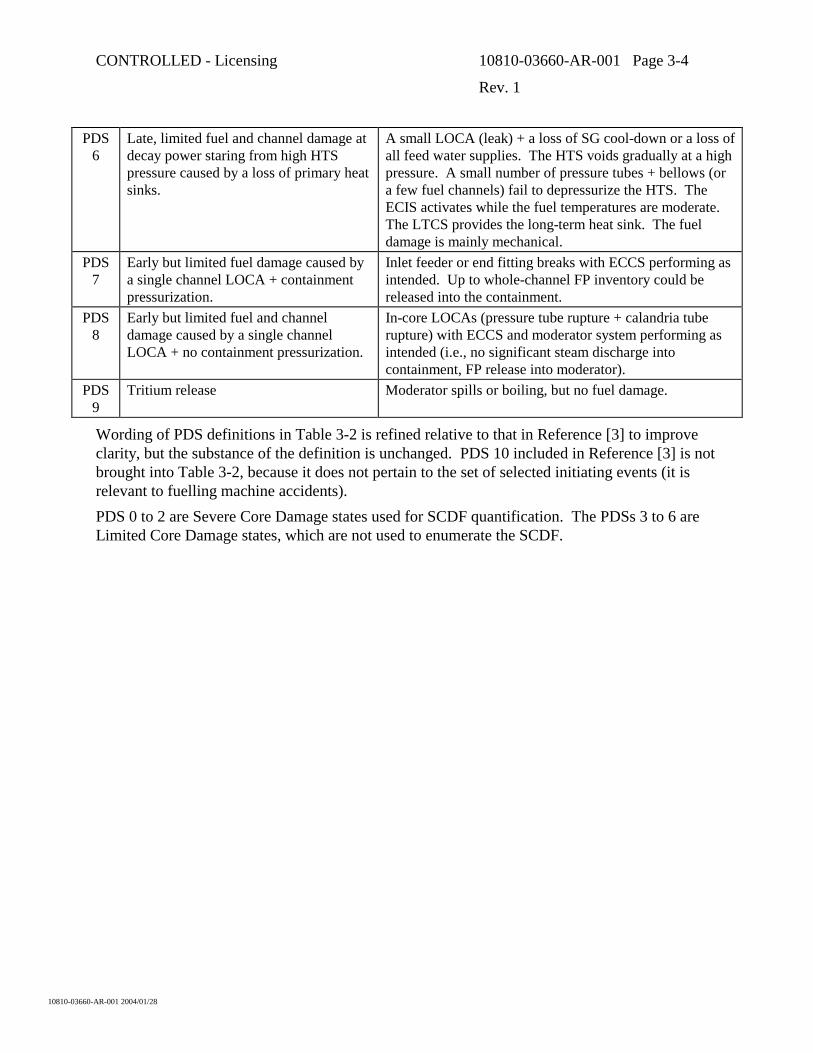
Development of event trees includes the assessment of Plant Damage State (PDS) resulting from accident progression through a particular sequence in the event tree. The PDS used in this report are defined in Table 3-2. These states are a subset of standard states in Reference [3].
Table 3-2 Plant Damage States
PDS 0
Early loss of core integrity at high power and pressure as a result of a failure to shutdown when required.
This PDS is assigned to end states resulting from failure of all shutdown functions when the shutdown is required to mitigate a power-cooling mismatch. The reactor core disassembles at high internal pressure
PDS 1
Late loss of core integrity at decay power starting from high HTS pressure caused by a loss of all primary and backup heat sinks.
Loss of primary heat sinks at HTS high pressure (e.g., loss of FW + SW + RWS make-up to SGs). A small number of channels fail to relieve HTS pressure, but ECC and moderator heat sinks are unavailable. The reactor core disassembles at low internal pressure. The core debris can be retained in the calandria if the shield water heat sink is available.
PDS 2
Late loss of core integrity at decay power starting from low HTS pressure caused by a loss of all primary and backup heat sinks.
LOCA + LOECC + loss of moderator heat sink. The reactor core disassembles at low internal pressure. The core debris can be retained in the calandria if the shield water heat sink is available.
PDS 3
Early, widespread fuel and channel damage at decay power starting from low HTS pressure caused by a loss of primary heat sinks + a failure of ECCS.
LOCA + LOECC cause rapid core voiding (e.g., large LOCA + failure of ECIS and LTCS). The moderator heat sink is available to maintain the fuel within the fuel channels, which are deformed but intact.
PDS 4
Late, widespread fuel and channel damage at decay power starting from low HTS pressure caused by a loss of primary heat sinks + a failure of ECCS.
LOCA + LOECC cause slow core voiding (e.g., a small LOCA + failure of ECIS & LTCS or any size LOCA + failure of LTCS). Moderator heat sink is available to maintain the fuel within the fuel channels, which are deformed but intact.
PDS 5
Early, limited fuel damage at decay power starting from low HTS pressure caused by a loss of primary heat sinks.
LOCA with ECCS performing as intended. No temperature-induced fuel failures, but some incipient cladding defects open. All pressure tubes remain intact.
CONTROLLED - Licensing 10810-03660-AR-001 Page 3-4
Rev. 1
10810-03660-AR-001 2004/01/28
PDS 6
Late, limited fuel and channel damage at decay power staring from high HTS pressure caused by a loss of primary heat sinks.
A small LOCA (leak) + a loss of SG cool-down or a loss of all feed water supplies. The HTS voids gradually at a high pressure. A small number of pressure tubes + bellows (or a few fuel channels) fail to depressurize the HTS. The ECIS activates while the fuel temperatures are moderate. The LTCS provides the long-term heat sink. The fuel damage is mainly mechanical.
PDS 7
Early but limited fuel damage caused by a single channel LOCA + containment pressurization.
Inlet feeder or end fitting breaks with ECCS performing as intended. Up to whole-channel FP inventory could be released into the containment.
PDS 8
Early but limited fuel and channel damage caused by a single channel LOCA + no containment pressurization.
In-core LOCAs (pressure tube rupture + calandria tube rupture) with ECCS and moderator system performing as intended (i.e., no significant steam discharge into containment, FP release into moderator).
PDS 9
Tritium release Moderator spills or boiling, but no fuel damage.
Wording of PDS definitions in Table 3-2 is refined relative to that in Reference [3] to improve clarity, but the substance of the definition is unchanged. PDS 10 included in Reference [3] is not brought into Table 3-2, because it does not pertain to the set of selected initiating events (it is relevant to fuelling machine accidents). PDS 0 to 2 are Severe Core Damage states used for SCDF quantification. The PDSs 3 to 6 are Limited Core Damage states, which are not used to enumerate the SCDF.
CONTROLLED - Licensing 10810-03660-AR-001 Page 4-1
Rev. 1
10810-03660-AR-001 2004/01/28
4. METHODOLOGY
The methodology used for this preliminary event tree analysis is described in Section 4 of Reference [3].
4.1 Overview
Event tree analysis is carried out for each initiating event in Table 3-1. The event tree depicts various possible sequences, which could occur after the initiating event, by modeling combinations of mitigating system availabilities or unavailabilities.
Each event tree starts with the initiating event, and then develops through a logical set of branch points. Each branch point represents the success (upward direction) or failure (downward direction) of a pertinent mitigating system. The event tree is horizontally oriented, and is read from left (the initiating event) to right (sequence endpoints).
Each sequence in a tree concludes when one of the following conditions exist;
• The reactor has been shut down and decay heat is being adequately removed. No significant plant damage has resulted. Such sequences are labelled “S” (success).
• Failures have resulted in some degree of plant damage. Depending on the initiating event, whether shutdown has occurred or not, and how (if at all) decay heat is being removed, a label is assigned from the listing of PDS in Table 3-2.
• The estimated frequency of the sequence is so low that further study is not meaningful. These sequences are labelled “NDF” (not developed further). A sequence is terminated and labelled “NDF” when its estimated frequency is lower than 1.0 x 10⁻⁹ events per year and further mitigating systems are available.
The preliminary event trees for ACR are of intermediate to large size. Separate branch points are assigned not only to heat sinks, but also to the operator actions and services which are required to support the heat sinks (e.g., electrical power and service water). The software used to draw and evaluate the trees is the personal-computer-based program “ETA-II” (Reference [4]).
4.2 Mitigating Systems
During event tree development, questions are asked about the success/failure of various mitigating functions identified in Section 5.
Class I, Class II control power and the Distributed Control systems are not shown in the event trees, since this would have made the trees unmanageable. Dependencies unaccounted for in the preliminary event trees due to these systems will be considered in a latter PSA phase, using fault tree analysis and accident sequence quantification.
CONTROLLED - Licensing 10810-03660-AR-001 Page 4-2
Rev. 1
10810-03660-AR-001 2004/01/28
For the screening assessments in this report, the functions of active mitigating systems are treated comprehensively, but the passive water make up from the RWS is modelled on as-required basis (see Section 1).
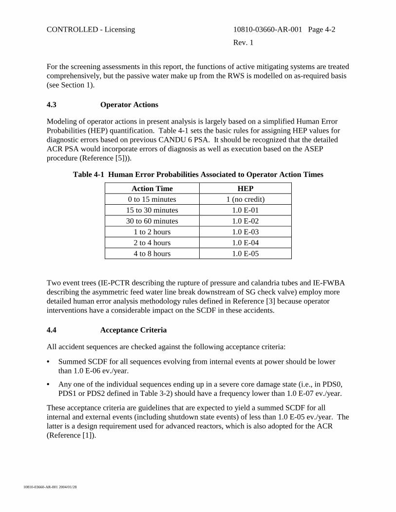
4.3 Operator Actions
Modeling of operator actions in present analysis is largely based on a simplified Human Error Probabilities (HEP) quantification. Table 4-1 sets the basic rules for assigning HEP values for diagnostic errors based on previous CANDU 6 PSA. It should be recognized that the detailed ACR PSA would incorporate errors of diagnosis as well as execution based on the ASEP procedure (Reference [5])).
Table 4-1 Human Error Probabilities Associated to Operator Action Times
Action Time HEP 0 to 15 minutes 1 (no credit) 15 to 30 minutes 1.0 E-01 30 to 60 minutes 1.0 E-02
1 to 2 hours 1.0 E-03 2 to 4 hours 1.0 E-04 4 to 8 hours 1.0 E-05
Two event trees (IE-PCTR describing the rupture of pressure and calandria tubes and IE-FWBA describing the asymmetric feed water line break downstream of SG check valve) employ more detailed human error analysis methodology rules defined in Reference [3] because operator interventions have a considerable impact on the SCDF in these accidents.
4.4 Acceptance Criteria
All accident sequences are checked against the following acceptance criteria:
• Summed SCDF for all sequences evolving from internal events at power should be lower than 1.0 E-06 ev./year.
• Any one of the individual sequences ending up in a severe core damage state (i.e., in PDS0, PDS1 or PDS2 defined in Table 3-2) should have a frequency lower than 1.0 E-07 ev./year.
These acceptance criteria are guidelines that are expected to yield a summed SCDF for all internal and external events (including shutdown state events) of less than 1.0 E-05 ev./year. The latter is a design requirement used for advanced reactors, which is also adopted for the ACR (Reference [1]).
CONTROLLED - Licensing 10810-03660-AR-001 Page 5-1
Rev. 1
10810-03660-AR-001 2004/01/28
5. RELIABILITY TARGETS
To help meet the ACR target for summed SCDF, the system reliability targets for ACR were established based on simple fault tree analysis for ACR systems, previous CANDU 6 and CANDU 9 PSA experience and/or engineering judgment. These targets (see Table 5-1 and Table 5-2) were set at the start of the ACR design assist PSA work with the objective to satisfy the acceptance criteria in Section 4.4 and they are used in this report.
The reliability targets in Table 5-1 and Table 5-2 are currently being verified by detailed fault tree analysis of the latest ACR design configuration.
CONTROLLED - Licensing 10810-03660-AR-001 Page 5-2
Rev. 1
10810-03660-AR-001 2004/01/28
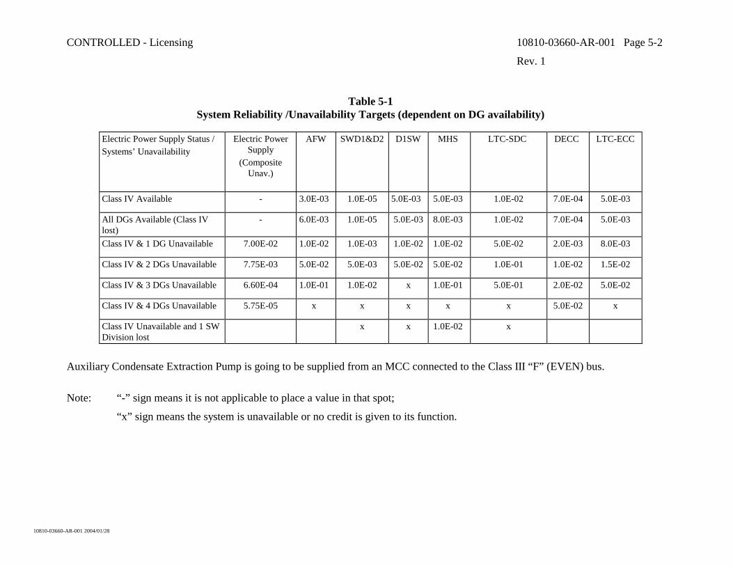
Table 5-1 System Reliability /Unavailability Targets (dependent on DG availability)
Electric Power Supply Status / Systems’ Unavailability
Electric Power Supply
(Composite Unav.)
AFW SWD1&D2 D1SW MHS LTC-SDC DECC LTC-ECC
Class IV Available - 3.0E-03 1.0E-05 5.0E-03 5.0E-03 1.0E-02 7.0E-04 5.0E-03
All DGs Available (Class IV lost)
- 6.0E-03 1.0E-05 5.0E-03 8.0E-03 1.0E-02 7.0E-04 5.0E-03
Class IV & 1 DG Unavailable 7.00E-02 1.0E-02 1.0E-03 1.0E-02 1.0E-02 5.0E-02 2.0E-03 8.0E-03
Class IV & 2 DGs Unavailable 7.75E-03 5.0E-02 5.0E-03 5.0E-02 5.0E-02 1.0E-01 1.0E-02 1.5E-02
Class IV & 3 DGs Unavailable 6.60E-04 1.0E-01 1.0E-02 x 1.0E-01 5.0E-01 2.0E-02 5.0E-02
Class IV & 4 DGs Unavailable 5.75E-05 x x x x x 5.0E-02 x
Class IV Unavailable and 1 SW Division lost
x x 1.0E-02 x
Auxiliary Condensate Extraction Pump is going to be supplied from an MCC connected to the Class III “F” (EVEN) bus.
Note: “-” sign means it is not applicable to place a value in that spot;
“x” sign means the system is unavailable or no credit is given to its function.
CONTROLLED - Licensing 10810-03660-AR-001 Page 5-3
Rev. 1
10810-03660-AR-001 2004/01/28
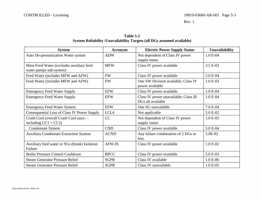
Table 5-2 System Reliability /Unavailability Targets (all DGs assumed available)
System Acronym Electric Power Supply Status Unavailability Auto De-pressurization Water system ADW Not dependent of Class IV power
supply status 1.0 E-04
Main Feed Water (excludes auxiliary feed water pumps sub-system)
MFW Class IV power available 3.5 E-03
Feed Water (includes MFW and AFW) FW Class IV power available 5.0 E-04 Feed Water (includes MFW and AFW) FW One SW Division available; Class IV
power available 1.0 E-03
Emergency Feed Water Supply EFW Class IV power available 1.0 E-04 Emergency Feed Water Supply EFW Class IV power unavailable; Class III
DGs all available 1.0 E-04
Emergency Feed Water System EFW One SG unavailable 7.0 E-04 Consequential Loss of Class IV Power Supply LCL4 Not applicable 5.0 E-02 Crash Cool (overall Crash Cool unav. – including CC1 + CC2)
CC Not dependent of Class IV power supply status
1.0 E-05
Condensate System CND Class IV power available 5.0 E-04 Auxiliary Condensate Extraction System ACND Any failure combination of 2 DGs or
less. 5.0E-02
Auxiliary feed water or SGs (break) Isolation Failure
AFW-IS Class IV power available 1.0 E-02
Boiler Pressure Control Cooldown BPCC Class IV power available 5.0 E-03 Steam Generator Pressure Relief SGPR Class IV available 1.0 E-06 Steam Generator Pressure Relief SGPR Class IV unavailable 1.0 E-05
CONTROLLED - Licensing 10810-03660-AR-001 Page 5-4
Rev. 1
10810-03660-AR-001 2004/01/28
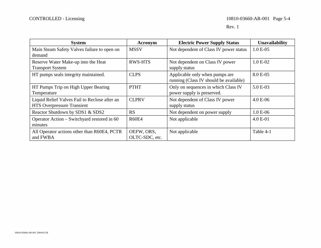
System Acronym Electric Power Supply Status Unavailability Main Steam Safety Valves failure to open on demand
MSSV Not dependent of Class IV power status 1.0 E-05
Reserve Water Make-up into the Heat Transport System
RWS-HTS Not dependent on Class IV power supply status
1.0 E-02
HT pumps seals integrity maintained. CLPS Applicable only when pumps are running (Class IV should be available)
8.0 E-05
HT Pumps Trip on High Upper Bearing Temperature
PTHT Only on sequences in which Class IV power supply is preserved.
5.0 E-03
Liquid Relief Valves Fail to Reclose after an HTS Overpressure Transient
CLPRV Not dependent of Class IV power supply status
4.0 E-06
Reactor Shutdown by SDS1 & SDS2 RS Not dependent on power supply 1.0 E-06 Operator Action – Switchyard restored in 60 minutes
R60E4 Not applicable 4.0 E-01
All Operator actions other than R60E4, PCTR and FWBA
OEFW, ORS, OLTC-SDC, etc.
Not applicable Table 4-1
CONTROLLED - Licensing 10810-03660-AR-001 Page 6-1
Rev. 1
10810-03660-AR-001 2004/01/28
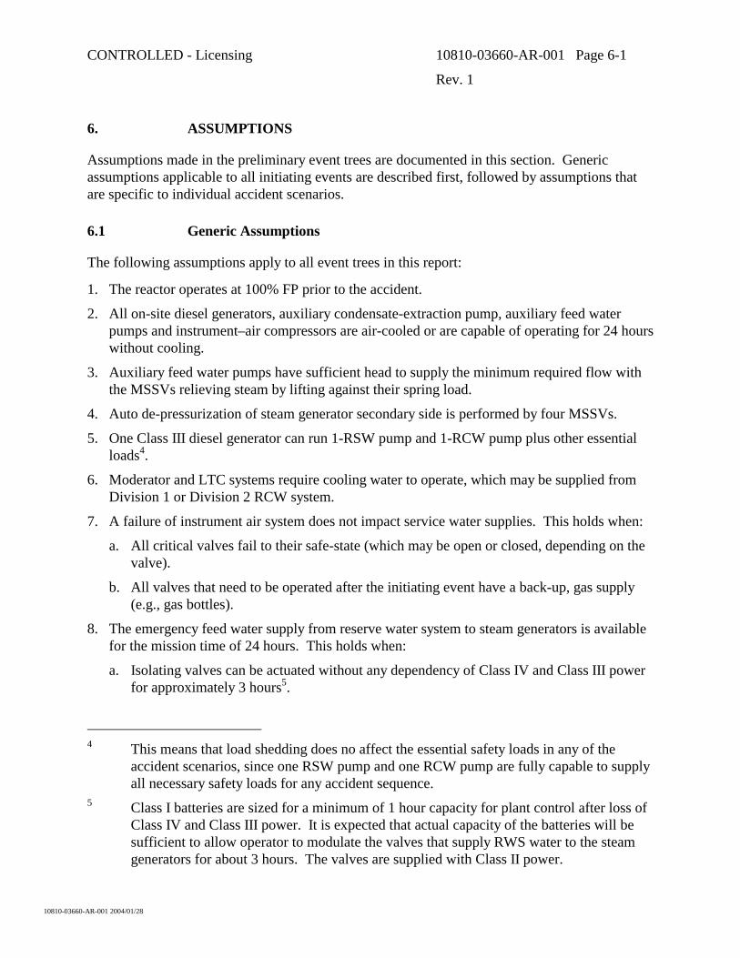
6. ASSUMPTIONS
Assumptions made in the preliminary event trees are documented in this section. Generic assumptions applicable to all initiating events are described first, followed by assumptions that are specific to individual accident scenarios.
6.1 Generic Assumptions
The following assumptions apply to all event trees in this report:
1. The reactor operates at 100% FP prior to the accident.
2. All on-site diesel generators, auxiliary condensate-extraction pump, auxiliary feed water pumps and instrument–air compressors are air-cooled or are capable of operating for 24 hours without cooling.
3. Auxiliary feed water pumps have sufficient head to supply the minimum required flow with the MSSVs relieving steam by lifting against their spring load.
4. Auto de-pressurization of steam generator secondary side is performed by four MSSVs.
5. One Class III diesel generator can run 1-RSW pump and 1-RCW pump plus other essential loads4.
6. Moderator and LTC systems require cooling water to operate, which may be supplied from Division 1 or Division 2 RCW system.
7. A failure of instrument air system does not impact service water supplies. This holds when:
a. All critical valves fail to their safe-state (which may be open or closed, depending on the valve).
b. All valves that need to be operated after the initiating event have a back-up, gas supply (e.g., gas bottles).
8. The emergency feed water supply from reserve water system to steam generators is available for the mission time of 24 hours. This holds when:
a. Isolating valves can be actuated without any dependency of Class IV and Class III power for approximately 3 hours5.
4 This means that load shedding does no affect the essential safety loads in any of the
accident scenarios, since one RSW pump and one RCW pump are fully capable to supply all necessary safety loads for any accident sequence.
5 Class I batteries are sized for a minimum of 1 hour capacity for plant control after loss of Class IV and Class III power. It is expected that actual capacity of the batteries will be sufficient to allow operator to modulate the valves that supply RWS water to the steam generators for about 3 hours. The valves are supplied with Class II power.
CONTROLLED - Licensing 10810-03660-AR-001 Page 6-2
Rev. 1
10810-03660-AR-001 2004/01/28
b. The same valves can be manually operated on long term basis (beyond 3 hours) in order to prevent spilling of water from the steam generators, thereby ensuring that RWS inventory can last for the mission time of 24 hours6.
c. The initiating event does not cause a discharge of HT coolant into the reactor building. When the reserve water tank and the open steam generators are interconnected, the containment envelope could be “bypassed” (i.e., the containment barrier would be provided only by the liquid pool in the reserve water tank and the associated piping)7.
9. Moderator pony motors are automatically provided with Class III power within a few minutes following a loss of Class IV power.
10. For all events that involve a small LOCA as an initiating event or a consequential failure, it is presumed that the post-accident break discharge is not large enough to remove decay heat from the HTS as liquid at saturation temperature or less. In this report, this is interpreted to mean that the ECC function of the LTC is not sufficient to act as a heat sink and that a steam generator heat sink is also required for these events.
11. It the absence of forced HTS circulation, steam generators provide effective heat sink only if both of them are available (i.e., it is presumed that thermosyphoning breaks down when only one steam generator is available)8.
6.2 Event Specific Assumptions
The following assumptions were applied to the event trees of selected initiating events:
6.2.1 Pressure Tube Rupture with Intact Calandria Tube
1. Coolant discharge through channel bellows is ~ 20 kg/sec and is beyond the capacity of H2O feed pump.
2. Manual reactor shutdown occurring before the first automatic trip is9 not credited, even though much more than 15 minutes would be available for the manual action before the automatic reactor trip on HTS low pressure comes in.
3. Steam generators are required to provide heat sink in conjunction with water make-up into the HTS (see Item 10 in Section 6.1).
4. The EFW supply from the RWS cannot be used (see Item 8c in Section 6.1).
6 This implies that provisions for manual operation of the RWS valves are available. 7 Opening of isolation valves between the RWS and the steam generators is inhibited by an
elevated reactor building pressure. 8 This is a conservative assumption made in the absence of deterministic analyses for
relevant HTS configuration. 9 This is a conservative assumption.
CONTROLLED - Licensing 10810-03660-AR-001 Page 6-3
Rev. 1
10810-03660-AR-001 2004/01/28
6.2.2 Pressure Tube/Calandria Tube Rupture
1. The initial discharge rate is > 100 kg/sec and thus well beyond the capacity of the H2O feed pumps.
2. The reactor trips automatically either on low HTS flow or on high moderator level.
3. Steam generators are required to provide heat sink in conjunction with water make-up into the HTS (see Item 10 in Section 6.1).
4. The EFW supply from the RWS cannot be used (see Item 8c in Section 6.1).
5. Moderator heat sink is not credited because a consequential hole is postulated to develop through lattice tube, which, in conjunctions with the broken channel, provides a path for calandria vessel draining down to the elevation of the affected channel.
6. Passive water supplies from RWS to HTS or calandria vessel are not credited10. Therefore, if this event coincides with a loss of both ECI and LTC, the moderator is not credited as heat sink because forced circulation through moderator heat exchangers may be impaired and no water make-up is available.
7. In order to defend calandria tube failure probability following a pressure tube rupture, the R&D program needs to demonstrate that the calandria tube will survive all relevant loading conditions. The program also needs to demonstrate that the calandria tube has a high creep rupture resistance. The latter is the ability of the calandria tube to withstand the elevated pressure and temperature environments after a pressure tube failure for long enough time so that operator action can be relied upon to reduce the HTS pressure. To afford high reliability credit for this operator action, the calandria tube needs to survive for about 2 hours or longer.
6.2.3 Feeder Break
1. No operator action is credited for reactor shutdown.
2. The RRS maintains approximately constant reactor power until the automatic reactor shutdown.
3. Steam generators are required to provide heat sink in conjunction with water make-up into the HTS (see Item 10 in Section 6.1).
4. The EFW supply from the RWS cannot be used (see Item 8c in Section 6.1).
5. Should steam generators be unavailable, the active heat removal by moderator system is credited as the back-up heat sink (provided a service water system is available). The passive heat removal in calandria vessel (by boiling and make-up from the RWS) is not credited.
10 Section 1 explains the rationale for not crediting the passive water supplies from the
RWS.
CONTROLLED - Licensing 10810-03660-AR-001 Page 6-4
Rev. 1
10810-03660-AR-001 2004/01/28
6.2.4 Feeder Stagnation Break with Consequential Channel Rupture
1. The break causes a severe power/cooling mismatch, resulting in a consequential channel rupture (i.e., an in-core break) at full power.
2. Reactor trips automatically on low HTS pressure, low HTS flow or high moderator level.
3. RRS maintains approximately constant power up to the reactor trip.
4. ECC systems (ECIS and LTCS) are automatically activated to refill the HTS and to maintain it full of water.
5. Steam generators are required to provide heat sink in conjunction with water make-up into the HTS (see Item 10 in Section 6.1).
6. The EFW supply from the RWS cannot be used (see Item 8c in Section 6.1).
7. Should the ECC make-up fail, water can be supplied from the RWS into the HTS for the duration of mission time at a sufficient rate to maintain the fuel channels flooded with water11.
8. Moderator heat sink is not credited because the ruptured bellows and the hole in the feeder in conjunction with the broken channel provide a path for calandria vessel draining down to the elevation of the affected channel12.
9. Should the HTS make-up or the supplementary steam generator heat sink be unavailable, the affected sequence is not developed any further and a Severe Core Damage is presumed13.
6.2.5 Loss of One Service Water Division
1. Loss of RCW cooling water to the main feed water and main condensate pumps causes them to trip early. Therefore, these pumps are not credited. The auxiliary feed water pumps are available.
2. The gland seals and bearings of the HT pumps are cooled by RCW water in the following configuration:
a. Each of the two HT pumps located on either side of the reactor are supplied with cooling water from one separate RCW division.
11 This assumption implies that the HTS remains depressurized for the gravity make-up to
work. It may not be consistent with earlier assumption (Item 5 in Section 6.2.4). Future analysis will explore and confirm this assumption.
12 In the event tree, the RWS make-up to the HTS was credited in case of failure of ECC, but success of crash cooldown.
13 This is an expedient and conservative assignment of PDS. The sequences could be developed further, likely resulting in one of the Limited Core Damage states. However, the conservative assignment of PDS is permissible for screening analysis (Section 1).
CONTROLLED - Licensing 10810-03660-AR-001 Page 6-5
Rev. 1
10810-03660-AR-001 2004/01/28
b. HT Pumps #1 and #3 are taken to be supplied from SW Division #1. HT Pumps #2 and #4 are taken to be supplied from SW Division #2.
3. Because the bleed cooler is presumed to be supplied by Division #2 service water, the cooling water to gland seals of HT pumps is not available. Failure of bleed control valves to close and bottle up the bleed condenser (CLPS) after the initiating event causes ingress of hot water into the suction of the pressure and inventory control (feed) pumps and into the HT pumps seals, in time causing consequential small LOCAs at two HTS locations due to failures of pump seals.
4. Affected HT pumps trip on high upper bearing temperature or are tripped manually within 1 hour of accident initiation.
5. Service water from Division #2 provides cooling water to LTC heat exchanger #2 that supplies water through RIH #2 and ROH #2. However, if needed, the operator can supply LTC heat exchangers from both service water divisions.
6. The discharge flow from the two-point, induced small LOCAs (caused by failure of HTS pumps seals) is assumed to exceed the capacity of HTS feed pumps.
7. For small LOCAs, steam generators are required to provide heat sink in conjunction with water make-up into the HTS (see Item 10 in Section 6.1).
8. The EFW supply from the RWS cannot be used (see Item 8c in Section 6.1).
9. Instrument air compressors continue running on loss of RCW (see Item 2 in Section 6.1).
10. A failure to trip pumps automatically or manually is presumed to cause a two-point large LOCA. ECC systems are ineffective for two-point large LOCA14 and cannot be credited in such sequence.
11. The inter-unit service water supply back-up is not credited.
6.2.6 Loss of Class IV Power Supply
1. The reactor shuts down either on low HT flow or high HT pressure.
2. The following equipment is affected:
a. Turbine generator trips.
b. HT pumps stop running. In the absence of forced HT flow, both steam generators are required to provide the heat sink (see Item 11 in Section 6.1).
c. Main feed water pumps stop running.
d. Main condensate extraction pumps stop running.
e. Condenser cooling water pumps stop running.
f. Pressurizer heaters cannot be energized. 14 All injected water could drain out from the HTS without reaching the fuel.

CONTROLLED - Licensing 10810-03660-AR-001 Page 6-6
Rev. 1
10810-03660-AR-001 2004/01/28
g. Boiler pressure control cool-down program is available. This program uses ASDVs and CSDVs to cool down the steam generators, but CSDVs do not open when Class IV power is unavailable.
3. All four diesel generators supplying Class III power start automatically following the loss of Class IV power. These diesel generators do not require external cooling water to operate (Item 2 in Section 6.1).
4. When Class III power is available:
a. All auxiliary feed water pumps are energized (distributed as one pump per Class III bus).
b. Auxiliary condensate pump is available (see Item 2 in Section 6.1).
c. Instrument air system is available (see Item 2 in Section 6.1).
d. Two of the four LTC pumps are energized.
5. If Class III power is also lost:
a. Auto depressurization water system (ADW) will depressurize steam generators on a low steam generator level plus timer. Isolation valves between RWS and steam generators open automatically on this signal, unless inhibited by a signal of high reactor building pressure (see Item 8c in Section 6.1).
b. MSSVs are remotely ‘gagged open’ from the Main Control Room.
c. Water can be supplied from the RWS to the steam generators for the mission time of 24 hours (see Item 8 in Section 6.1).
6. A failure of a liquid relief valve to re-close constitutes a consequential small LOCA. This means that:
a. The EFW supply from the RWS cannot be used (see Item 8c in Section 6.1).
7. Multiple failures of ASDVs, CSDVs and MSSVs to open produce a Main Steam Line Break15.
6.2.7 Loss of Inventory in Shield Cooling System
1. The system is designed such that the End Shields cannot be drained for any pipe break location.
2. Fuel channel integrity (and thus HTS integrity) is maintained for at least 8 hours for any shield water draining transient16.
15 The sequence is not developed beyond the steam line break, since it will be covered by
the Event Tree for the Main Steam Line Break. 16 This time is based on analyses of CANDU-9 design and needs to be verified for the ACR
design.

CONTROLLED - Licensing 10810-03660-AR-001 Page 6-7
Rev. 1
10810-03660-AR-001 2004/01/28
3. EFW supply from the RWS into the steam generators is available if required. It would be manually stopped once the shutdown cooling function of the LTC system is operational.
4. A water make-up from the RWS into the shield tank or the end shields is not credited. It is presumed that the make-up to the shield tank would be ineffective due to the draining through the break. Analyses are not available of thermal stresses due to a make-up of the end shields only.
6.2.8 Small Steam Discharge Causing Low Deaerator Level
The following assumptions are engineering judgements based on ‘Balance of Plant’ features of existing CANDU reactors. When this preliminary event tree analysis was performed, ACR-specific design details were not available.
The discharge rate for this event is chosen using the following considerations:
a) it should be high enough to cover an opening of a MSSV; and
b) it should be low enough to be within the supply capacity from the demineralized water tank (including the capacity of feed water regulating valves), such that the entire feed water inventory in the plant can be credited.
A steam discharge rate of 180 kg/s would be most challenging. It is presumed that the capacity of supply from the demineralized water tank can match this rate.
1. The turbine generator is unloaded at about 85% full power by the overall plant control programs.
2. Deaerator contains water inventory equivalent to 90 full power minutes at the steam discharge rate of 180 kg /sec before a signal for reactor power setback comes in on low deaerator level.
3. For this event tree, feed water supply from the reserve feed water tank (turbine building) or demineralised water storage tank to the suction of the auxiliary feed water pumps is not credited17. Therefore, a failure of condensate system or failures of valves in the gravity supply line from the demineralized water storage tank to the condenser hotwell constitutes a failure of auxiliary feed water system.
4. EFW supply from the RWS to steam generators can be manually established within ~3 hours without opening the MSSVs. The implicit assumption is that the small steam line break depressurizes the secondary side of steam generators to below the injection pressure of gravity make-up from the RWS in less than 3 hours.
17 This supply line is available in existing CANDU reactors, but its existence in the ACR
was not confirmed at the time when this analysis was performed.
CONTROLLED - Licensing 10810-03660-AR-001 Page 6-8
Rev. 1
10810-03660-AR-001 2004/01/28
6.2.9 Symmetric Feed Water Line Break Upstream of Feed Water LCVs
1. The reactor trips on low steam generator level.
2. Class IV power supply fails consequentially because the switchgear is located near the broken feed water line in the turbine building and it fails due to harsh environment resulting from a feed water discharge.
3. Following this feed water break:
a. The auxiliary feed water pumps remain available (they are environmentally qualified for this event, Reference [6]).
b. The condensate system is not available (it is not environmentally qualified).
4. The auto de-pressurization water system is available and will come in on sustained low steam generator level.
6.2.10 Asymmetric Feed Water Line Break Downstream of SG Check Valve
1. At least one of the HT pumps continues to operate for ~ 60 minutes into the accident18, providing forced circulation of HT coolant.
2. Auxiliary feed water is available to the intact steam generator when auxiliary feed water level control valves automatically close and isolate the steam generator with the break upon sensing a level discrepancy between the two steam generators.
3. The ECI system is poised to compensate for HTS coolant shrinkage that is not accommodated by the pressurizer19.
4. The EFW supply to steam generators is not available in the early stages of accident because the opening of RWS flow paths to steam generators is inhibited by a signal of high pressure in the reactor building (see Item 8d in Section 6.1). However, the operator can provide the EFW supply to steam generators upon confirming that HTS boundaries are intact. This could happen at 15 minutes into the accident or later.
6.2.11 Loss of Reactivity Control Leading to Core Power Excursion
This initiating event postulates power excursion which, if not arrested by timely shutdown, invariably leads to severe core damage in existing CANDU reactors (which all have a positive
18 HT pumps are not environmentally qualified for harsh environment in the reactor
building. This assumption is a best-estimate judgement that the actual pumps can operate for a period of time in harsh environment as long as the FW discharge does not impact the pump directly and the pumps do not cavitate. Both these preconditions are satisfied in this accident.
19 The pressurizer acting alone cannot accommodate the rapid HT coolant shrinkage in this accident, so HTS would depressurize below the injection pressure of the ECI system.

CONTROLLED - Licensing 10810-03660-AR-001 Page 6-9
Rev. 1
10810-03660-AR-001 2004/01/28
void reactivity coefficient). ACR is significantly different from existing CANDU reactors in this aspect by virtue of having a negative void reactivity coefficient. At the time when this event tree analysis was performed, the ACR response to power excursions had not been analyzed in any detail. This analysis presumes that the ACR would also end up is a severe core damage if the engineered shutdown systems were to fail. In this context, the only assumptions required for event tree developments are as follows:
1. Neutronic power measurements and calibration are carried out by devices offering at least the same level of performance as those employed in CANDU 6 plants.
2. The level of quality implemented in the design, manufacturing and commissioning of the reactor regulating system components for ACR will ensure the same reliability/unavailability for the systems functions as that of the CANDU 6. The frequency of loss of reactivity events is therefore assumed to be the same for ACR as the observed frequency for the operating CANDU 6 plants (4.24E-02 ev./year).
CONTROLLED - Licensing 10810-03660-AR-001 Page 7-1
Rev. 1
10810-03660-AR-001 2004/01/28
7. EVENT TREES
The selected initiating events and the associated event tree models discussed and analyzed in this section are all produced for an ACR-700 Unit, operating at full power and benefiting from the shared support services available from the twin Units.
7.1 Pressure Tube Rupture with Intact Calandria Tube
A failed pressure tube discharges HT coolant into the annulus, pressurizing it to approximately the HTS pressure. A few fuel rods in the affected pressure tube may be damaged during the initiating event due to mechanical forces imposed on the fuel by the pressure boundary failure.
7.1.1 Plant Response
The calandria tube withstands the hydrodynamic loading by the coolant20, but the bellows on both channel ends invariably fail. Instruments that monitor the annulus gas system produce several alarms in the MCR, which announce the pressure tube failure early into the accident. The Emergency Operating Procedures (EOPs) will call for an orderly, manual shutdown of the reactor when these alarms are produced21. However, an early manual shutdown is not credited.
The two coolant discharge paths from the HTS are through small clearances past the end fitting bearings at each end of affected channel, so the coolant flow rates will be small. An engineering judgment is that the total leak rate from the ACR would be on the order of 20 kg/s, which is assumed to be beyond the make-up capacity of HT pressurizing pumps.
With a very small net loss of coolant from the HTS, water levels in the storage tank and the pressurizer decrease very slowly. After a certain time (which depends on the net coolant loss rate), the reactor automatically trips on low HT pressure. The reactor is shut down automatically before the pressurizer reaches its low level setpoint and before the storage tank becomes empty (without employing the back-up supply to the storage tank). Low level alarms from the pressurizer and the storage tank also give the operator ample time (>> 15 minutes) to shut down the reactor before any of HTS volumes would start to void due to the loss of coolant.
In the time period before the reactor is shut down, the RRS will maintain the power at preset value. Following the shutdown, the ECI system is activated on a sustained low HT pressure signal. A crash cool down of steam generators, which accompanies the ECI system activation, quickly reduces the HTS pressure to below the injection pressure. The injection of emergency coolant from the pressurized accumulator tanks refills the HTS and stabilizes the HTS pressure. The HT pumps are likely to still be running, producing a considerable heat load in addition to
20 Should the calandria tube fail, this constitutes a more or less simultaneous pressure tube
and calandria tube rupture which is analyzed as a separate Initiating Event in Section 7.2. 21 This is an expectation based on existing CANDU reactors. The EOPs for the ACR have
not yet been developed.
CONTROLLED - Licensing 10810-03660-AR-001 Page 7-2
Rev. 1
10810-03660-AR-001 2004/01/28
fuel decay heat. Steam generators provide the heat sink for the post-accident heat load (i.e., heat discharged through the bellows is negligible relative to heat taken in by the feed water).
During a slow HTS depressurization that follows, the HT pumps are turned off and the ECI accumulator tanks drain. When the inventory in these tanks is depleted, the tanks are isolated and a pumped water supply from the LTC-ECC system commences. At this juncture, the HTS leak rate is very small because the driving pressure is low. The LTC-ECC system acts primarily as the make-up system for the HTS. Its heat exchangers deal only with a very small fraction of HTS heat that enters the containment as part of coolant discharge. The vast majority of HTS heat is dissipated to the steam generators. The passive make-up of steam generators from the RWS cannot be used in this accident (see Item 8c in Section 6.1).
The plant conditions at the end of mission time (at 24 hours) are stable. The fuel damage has been limited to the early fuel failures caused by the initiating event (i.e., no additional fuel failures). Long term actions (beyond the scope of this report) will remove the damaged fuel from the reactor and replace the damaged fuel channel.
7.1.2 Event Tree
The initiating event label is IE-PTR (Table 3-1). Event tree details are presented in Appendix A.
Severe core damage plant damage states are assigned for:
• A failure to shut down the reactor. A failure to depressurize the HTS such that a coolant make-up is not possible.
• A failure to provide service water to active mitigating systems. • Failures of ECC systems to provide make-up for the depressurized HTS in conjunction with a
failure of moderator system to provide an alternate heat sink. Note that only the ‘active’ heat sink mode of moderator system is modelled (i.e., the pumps and the heat exchangers). The ‘passive’ mode of ‘moderator as a heat sink’, which involves boiling off water in the calandria vessel and water make-up from the RWS is well suited for this type of accident, so the severe core damage frequency will be lower when these passive ACR features will be modelled.
7.2 Pressure Tube/Calandria Tube Rupture
Calandria tubes of the ACR are designed to withstand the hydrodynamic loads imposed by pressure tube failure. This initiating event thus involves a gradual creeping of calandria tube wall to failure. This can be mitigated by operator actions, because several hours are available before the calandria tube would creep to failure. The initiating event frequency (Table 3-1) is based on the operator failing to prevent the calandria tube rupture by creep. Given that more than two hours would be available for this action22, a combined failure probability of 1.50E-2 can be 22 This is based on a conservative assessment of the minimum time to creep failure and will
be confirmed.
CONTROLLED - Licensing 10810-03660-AR-001 Page 7-3
Rev. 1
10810-03660-AR-001 2004/01/28
assigned23. This initiating event frequency is thus based on the pressure tube failure frequency and the preceding operator failure probability.
7.2.1 Plant Response
The failure of both pressure and calandria tubes discharges high-enthalpy HT coolant and a small amount of mechanically broken fuel (up to 12 fuel bundles) into the calandria vessel. One or more calandria rupture disks burst to provide overpressure protection for the calandria vessel. Broken fuel releases some of its volatile fission products, which are subjected to a ‘pool scrubbing’ before being released into the containment. The energy release into the containment depends on the elevation of ruptured channel. A channel at high elevation could release much of the energy contained in the two-phase HT coolant discharge. A channel at low elevation would release little energy into the containment, because steam is condensed within the calandria vessel. A small energy release into the containment is considered in this analysis.
The rupture constitutes a small LOCA with an initial discharge rate in excess of 100 kg/s24. A generic presumption for all small LOCAs is that these breaks require the steam generator heat sink to be available in order to avoid additional fuel failures (see Item 10 in Section 6.1 and its associated footnotes). The passive make-up of steam generators from the RWS cannot be used in this accident because of containment bypass considerations (see Item 8c in Section 6.1).
The reactor trips automatically shortly after the in-core rupture . There is some damage to the in-core devices caused by the channel rupture, but this damage does not impair the ability of either shutdown system to quickly reduce the reactor power to decay power level and keep the reactor shut down thereafter25.
In this analysis, a consequential opening of a sizeable flow path between the calandria vessel and the containment is presumed at a low core elevation, which prevents the moderator from acting as a heat sink (see Item 5 in Section 6.2.2). This events assumes an end fitting ejection. Its effect is that severe core damage is assigned when either of the ECI or LTC functions are lost.
The HTS depressurizes, it is refilled by water injection from the ECI system and maintained full of water in the long term by water injection from the LTC-ECC subsystem. The HTS pumps are
23 This value accounts for event diagnosis as well as the execution errors related to shutting
down the reactor and reducing the HTS pressure and temperature by means of ‘boiler pressure control cool-down’ program and is based on the methodology in Reference [3]).
24 This is based on analyses for existing CANDU reactors . The range of break discharge rates for the ACR is yet to be quantified.
25 Consequences of in-core ruptures have not yet been evaluated for the ACR. However, the basic prerequisite for all CANDU reactor designs is that an in core rupture does not impair either of the shutdown functions. It is safe to assume that the ACR will meet this requirement.
CONTROLLED - Licensing 10810-03660-AR-001 Page 7-4
Rev. 1
10810-03660-AR-001 2004/01/28
tripped or turned off before the injection from the ECI accumulator tanks stops. HTS heat removal is shared between the steam generators and the LTC heat exchangers. In this case, the LTC heat exchangers dissipate a considerable fraction of the HTS heat.
The plant conditions at the end of mission time (at 24 hours) are stable. The fuel damage has been limited to the early fuel damage caused by the initiating event (i.e., no additional fuel damage). Long term actions (beyond the scope of this report) will remove the damaged fuel from the reactor and replace the damaged fuel channel.
7.2.2 Event Tree
The initiating event label is IE-PCTR (Table 3-1). Event tree details are presented in Appendix B.
Severe core damage plant damage states are assigned for:
• A failure to shut down the reactor
• A failure to depressurize the HTS by engineered means (i.e., steam generator crash cool-down) such that a coolant make-up is not possible.
• A failure to provide service water to active mitigating systems..
• Failures of ECC systems to provide make-up for the depressurized HTS, since the alternate moderator heat sink is presumed unavailable due to draining of the calandria vessel (Item 5 in Section 6.2.2).
• Failures of active steam generator heat sinks, since the LTC-ECC may not be able to remove the HTS heat (Item 10 in Section 6.1) the passive RWS supply to steam generators cannot be used (Item 8c in Section 6.1) and the alternate moderator heat sink is presumed unavailable due to draining of the calandria vessel (Item 5 in Section 6.2.2).
7.3 Feeder Break
Inlet or outlet feeder pipes would typically fail without causing any appreciable power-cooling mismatch in the affected fuel channel. Any outlet feeder break can only accelerate the flow through the affected channel. An inlet feeder break could reduce the forward flow (very small break), deteriorate the channel flow to very low values (so-called feeder stagnation break analyzed in Section 7.4) or reverse the channel flow (larger breaks). This section analyzes the off-stagnation breaks, which include all outlet feeder breaks and the vast majority of break sizes and locations on the inlet feeders. In the absence of local power-cooling mismatch, these breaks are not appreciably different from small LOCAs in reactor headers or other HTS piping. All pressure tubes and calandria tubes are intact after the initiating event.
CONTROLLED - Licensing 10810-03660-AR-001 Page 7-5
Rev. 1
10810-03660-AR-001 2004/01/28
7.3.1 Plant Response
The reactor is tripped on low heat transport system pressure, low heat transport system flow or high reactor building pressure.
The ECC conditioning signal is generated on sustained low heat transport system pressure. It activates the crash cool-down of steam generators, opens the isolation valves of ECI accumulator tanks and readies the LTC-ECC subsystem for longer term injection.
The injection from ECI accumulator tanks refills the HTS. Running HT pumps provide forced flow through steam generators to maintain the heat sink. Some fraction of HTS heat (which depends on the break size) is carried into the containment by the discharging HT coolant. The HT pumps are tripped or turned off before the ECI accumulator inventory depletes and the long –term injection by the LTC-ECC system commences. The steam generators continue to serve as heat sinks (Item 10 in Section 6.1) in conjunction with LTC heat exchangers. The fractions of heat transferred to these two heat sinks depend on the break size.
The plant conditions at the end of mission time (at 24 hours) are stable. The fuel damage has been limited to incipient fuel defects which had opened during the HTS depressurization. Long term actions (beyond the scope of this report) will isolate the affected channel (e.g., freeze plugs), de-fuel it and repair the broken feeder.
7.3.2 Event Tree
The initiating event label is IE-FBIO ((Table 3-1). Event tree details are given in Appendix C.
The assignments of severe core damage states are identical to those for the pressure tube rupture with intact calandria tube (Section 7.1), since both these accidents are small LOCAs on the lower end of break size spectrum with no fuel damage after the initiating event, other than the mechanically damaged fuel in the channel with the ruptured pressure tube. The rationale for assignments of severe care damage states and the qualifying comments in Section 7.1 apply here as well.
7.4 Feeder Stagnation Break
Certain breaks in inlet feeder pipes can deteriorate (i.e., essentially stagnate) the coolant flow in the affected channel while the reactor is at power. For a severe power cooling mismatch, the fuel would overheat to induce a consequential pressure tube rupture. The pressure tube ruptures either because its wall heats up by convection from a superheated steam, or because the hot fuel materials come into contact with pressure tube wall. The conditions at consequential tube rupture are different from those during a spurious tube rupture. Hot gases or fuel materials impacting on the calandria tube make its consequential failure quite likely, while the flashing HT coolant at saturation temperature does not pose an immediate challenge to the calandria tube integrity.
CONTROLLED - Licensing 10810-03660-AR-001 Page 7-6
Rev. 1
10810-03660-AR-001 2004/01/28
This section analyzes an inlet feeder break that induces a severe power cooling mismatch and leads to a more-or-less simultaneous rupture of both pressure and calandria tubes.
7.4.1 Plant Response
In terms of plant response, this accident is closely similar to the delayed channel rupture in Section 7.2. Automatic reactor trip times on some process parameters will differ because the pressurizer and storage tank inventories are different at the time of in-core rupture. However, this does not impact the potential for propagation to severe core damage. The damage to the in-core devices could be more severe for this accident, because superheated steam and some molten fuel materials are discharged following the severe power-cooling mismatch in the affected channel. However, this does not impact the shutdown capability, which must be maintained for either accident (see Footnote 25 on Page 7-3).
After the initial transient, the plant response is the same as that described in Section 7.2.1. However, for the feeder stagnation break, the passive water supply from the RWS to the HTS is modelled (which is not modelled for the in-core rupture in Section 7.2). This is done in order to reduce the individual-sequence SCDF to below the target value of 1E-7 events per year.
The credited water make-up by gravity into the depressurized HTS is feasible for this accident as well as for the delayed in-core rupture in Section 7.2. In both these accidents, the moderator heat sink is uncertain because of the postulated hole in the calandria vessel boundary at low core elevation ((Item 5 in Section 6.2.2 and Item 8 in 6.2.4). The RWS make-up to steam generators cannot be used because of the containment bypass considerations (see (Item 8c in Section 6.1). Hence, RWS water inventory is not used for other purposes (other than to provide a sufficient net pumps suction head for the LTC pumps) and is available for HTS make-up. The HTS make-up ends up in the calandria vessel in any case, so there is no conflict as to which process volume to supply with gravity make-up.
7.4.2 Event Tree
The initiating event label is IE-FSB. Event tree details are presented in Appendix D. The assignments of severe core damage states are identical to those for the delayed in-core rupture (Section 7.2.2) except for the failure of the LTC-ECC subsystem. Sequences for this failure are developed further to consider the HTS make-up from the RWS. When LTC-ECC is unavailable to provide long term make-up and partial heat removal, a severe core damage state is assigned when: • Gravity supply from the RWS is not established.
• Gravity supply from the RWS is successfully established, but a steam generator heat sink is not available to satisfy the conditions of Item 10 in Section 6.1.
CONTROLLED - Licensing 10810-03660-AR-001 Page 7-7
Rev. 1
10810-03660-AR-001 2004/01/28
7.5 Total Loss of One Service Water Division
A total loss of service water in a division means that there is no RCW flow, or there is no cooling of RCW system (i.e., no RSW flow through the heat exchangers between the RSW and RCW systems), in the division. This section examines the total loss of Division 2 service water system, which supplies the bleed condenser cooler.
A random failure of the expansion joints is not modelled. The plant response for this failure differs from that for the normal loss of service water, because consequential flooding becomes an issue. Flooding analyses are not within the scope of present work26.
7.5.1 Plant Response
Following the total loss of Division 2 service water, the moderator temperature rises. The temperature-induced swell triggers a reactor power setback within minutes. If the setback fails and the temperature-induced swell continues, the reactor will trip on high moderator level (SDS1 and/or SDS2) shortly thereafter.
Shutting down the reactor significantly reduces the moderator heat load (the nuclear heating in the dominant component of the heat load). The moderator temperature continues to rise slowly providing a number of hours before heavy water would start to boil27. The operator can further reduce the heat load to moderator by cooling down the HTS. The HTS cool-down slows down, arrests or reverses the moderator temperature rise28.
The HTS response depends on whether or not the initiating event induced a consequential LOCA (i.e., the pump seal failures) and on the responses of numerous systems as described by the event tree in Appendix E.
7.5.2 Event Tree
The Initiating Event label is IE-SWD2. Event tree details are presented in Appendix E.
Whether or not the consequential LOCA develops, a severe core damage plant damage state is assigned for a failure to shut down the reactor. Sequences for a failure of steam generator pressure relief in a shutdown reactor are not developed. Such failure will result in a main steam
26 This failure will be addressed in flooding PSA. 27 Analyses for the ACR are not yet available. Extrapolating CANDU-6 data and taking
into account the smaller moderator volume in the ACR, the adiabatic heat-up would take 3 to 4 hours to the onset of boiling. Heat losses to the cooler shield water on the outside of calandria vessel would extend this time considerably.
28 In principle, the HTS can be used as a heat sink for the moderator if the HT coolant temperature is reduced below the saturation temperature of heavy water at calandria relief setpoint, which is feasible.
CONTROLLED - Licensing 10810-03660-AR-001 Page 7-8
Rev. 1
10810-03660-AR-001 2004/01/28
line break, which will be analysed in a separate event tree in conjunction with a loss of service water.
Assignments of severe core damage states following loss of Division 2 service water depend on the mitigating systems availabilities. For consequential LOCA sequences, the rationale for assignments of severe core damage states and the qualifying comments in Section 7.1 apply here as well. For non LOCA sequences, where both Division 2 and 1 service water are lost, PDS1 is assigned. If division 1 service water is available then PDS6 is assigned.
7.6 Loss of Class IV Power to One Unit
This initiating event is the total loss of Class IV electrical power supply distribution system to one unit of a two-unit ACR station. The total loss of Class IV power supply is defined as the loss of power to both 5314-BUA (and hence 5324-BUC, 5323-BUE) and 5314-BUB (and hence 5324-BUD, 5323-BUF) Class IV buses. It is assumed that, following a loss of grid, the second unit remains operational.
All four diesel generators supplying Class III power start automatically following this initiating event (Item 3 in Section 6.2.6). Class III power supply would normally be available within a few minutes of losing Class IV power.
7.6.1 Plant Response
The equipment affected by this initiation event is listed in Section 6.2.6.
The steam generator inventory can provide “passive” HTS heat sink for approximately 2 hours provided the steam relief via spring-loaded MSSVs is available. This analysis assumes that the passive steam generator heat sink would last for 1 hour into the accident.
Heat sinks designated to mitigate this initiating event are:
1. The steam generators supplied by main or auxiliary feed water, when Class IV power is restored quickly.
2. The steam generators supplied by auxiliary feed water when Class III power is available.
3. The LTC system when Class III power is automatically restored by the diesel generators.
4. The steam generators supplied from RWS, when Class III power cannot be restored and only Class I and II power supplies are available.
The plant response depends on the number and timing of power supplies availability. This response can be altered by early failures which affect power generation (reactor shutdown), the passive steam generator heat sink (steam relief via MSSVs) and pressure boundary integrity (re-closure of HT liquid relief valves).
CONTROLLED - Licensing 10810-03660-AR-001 Page 7-9
Rev. 1
10810-03660-AR-001 2004/01/28
7.6.2 Event Tree
The initiating event label is IE-LCL4 (Table 3-1). Event tree details are presented in Appendix F.
Severe core damage plant damage states are assigned for:
• A failure to shut down the reactor.
• A failure to provide service water to active mitigating systems. A loss of Class IV and Class III electrical power and loss of RWS to the steam generators.
7.7 Loss of Inventory in the Shield Cooling System
The inventory loss is due to a pipe break in the shield cooling system. This break drains the inventory in the shield tank, but not in the end shields (Item 1 in Section 6.2.7). Up to 8 hours is available to prevent excessive stresses in the reactor assembly (Item 2 in Section 6.2.7).
7.7.1 Plant Response
The reactor is shutdown by a power setback on a low level in the head tank. The operator confirms and ensures that the reactor is shutdown within 8 hours with a success probability of 1.0.
For normal mitigation, operator manually cools down the reactor using the boiler pressure control cool-down program (via ASDVs and CSDVs) and employs the shutdown cooling subsystem of LTC system.
If normal mitigation cannot be preformed, the operator employs other available systems as described in the event tree.
7.7.2 Event Tree
The initiating event label is IE-SCB (Table 3-1). Event tree details are given in Appendix G.
7.8 Small Steam Discharge Causing Low Level in Deaerator
This event is a small steam discharge of 180 kg/s resulting (see Section 6.2.8 for rationale for choosing this discharge rate). The contributing events are (a) spurious opening of one MSSV and (b) small steam line failures. The dominant contributor is the spurious MSSV opening.
7.8.1 Plant Response
Following the initiating event, the deaerator level falls causing levels in the reserve feed water storage tank and in the hotwell to fall. The main condensate extraction pumps trip and auxiliary condensate extraction pump starts to continue depletion of feed water inventory.
CONTROLLED - Licensing 10810-03660-AR-001 Page 7-10
Rev. 1
10810-03660-AR-001 2004/01/28
Operator manually shuts down the reactor within 60 minutes with probability of 1.0E-04 in response to:
• power is automatically reduced to about 85% shortly after the initiating event due to falling steam generator pressure (Item 1 in Section 6.2.8).
• alarm on feed water/steam mismatch in steam generators;
• alarm on reactor power / turbine power mismatch;
• low-level indication in the condenser hotwell.
• Following the manual shutdown at 60 minutes, feed water inventory left in the deaerator is equivalent to ~ 3 hours of decay heat dissipation. The operator uses the boiler pressure controlled cool-down program (i.e., steam relief via ASDVs and CSDVs) to activate LTC-SDC system within this time in order to provide the long-term heat sink.
If no action is taken within 60 minutes, the deaerator level drops further and a reactor power setback on low deaerator level comes in at about 90 minutes into the accident (Item 2 in Section 6.2.8). The reactor is in a shutdown state in 3 minutes after the automatic setback. At this juncture, feed water inventory left in the deaerator is equivalent to ~ 1.5 hours of decay heat dissipation. As for the manual cooldown, the operator uses the boiler pressure controlled cool-down program to activate LTC-SDC system within this time in order to provide the long-term heat sink.
If the above normal mitigating actions cannot be performed because of additional failures, the operator uses the available systems as described in the event tree. The ultimate line of defence is the passive (gravity) make-up of steam generators from the RWS, which is invariably facilitated by the ‘passive’ steam generator depressurization via the postulated hole in the steam line boundary (see Item 4 in Section 6.2.8).
7.8.2 Event Tree
The initiating event label is IE-MSL3 (Table 3-1). Event tree details are given in Appendix H.
Severe core damage states are assigned to the following sequences:
• A failure to shut down the reactor; and
• Multiple failures which include a failure to establish the gravity EFW supply from the RWS.
For modelling this event tree, the condensate system was asked at the beginning of the ET. The availability of the condensate system, allows sufficient time for the operator to take action as feedwater is available (prior to reactor setback). This modelling simplified the ET development. The condensate was assigned a low unavailability value because for the initial period (3 hours) Class IV power is unlikely to fail. Some sequences (loss of Class IV electrical power) should be higher but the impact is not significant.

CONTROLLED - Licensing 10810-03660-AR-001 Page 7-11
Rev. 1
10810-03660-AR-001 2004/01/28
7.9 Symmetric Feed Water Line Break Upstream of Feed Water Control Valves
This break is located in the turbine building. It is assumed that Class IV electrical power fails consequentially (Item 2 in Section 6.2.9).
7.9.1 Plant Response
Steam generators quickly loose feedwater supply via the break and water level decreases. The reactor trips on low level in steam generators.
The equipment affected by the loss of Class IV electrical power is listed in Section 6.2.6. Additional equipment fails due to the harsh environment as listed in Item 3 of Section 6.2.9. Decay heat is transferred from the reactor core to the steam generators by thermosyphoning.
The automatic actions to mitigate this accident in a shutdown reactor is to auto-depressurize the steam generators (Item 4 in Section 6.2.9) and open the isolation valves for the gravity water supply from the RWS into the steam generators (Item 8 in Section 6.1).
If the gravity EFW supply is not available, but auto-depressurization is successful, it is assumed that the LTC-SDC subsystem can be manually activated.
7.9.2 Event Tree
The initiating event label is IE-FWBS (Table 3-1). Event tree details are presented in Appendix I.
The assignment of plant damage states is similar to other transient events.
7.10 Asymmetric Feed Water Line Break Downstream of the SG Check Valve
This break is located in the reactor building and it cannot be isolated from the affected steam generator.
7.10.1 Plant Response
The reactor trips automatically on a high reactor building pressure. The automatic trip on the low pressure in the feed line to steam generators would come in.
The affected steam generator drains and ceases to provide heat sink for the HTS.
Forced circulation of HT coolant is available for at least one hour (Item 1 in Section 6.2.10). This allows a single, unaffected steam generator to act as heat sink for the HTS (Item 11 in Section 6.1).

CONTROLLED - Licensing 10810-03660-AR-001 Page 7-12
Rev. 1
10810-03660-AR-001 2004/01/28
Since the affected steam generator is not taken to act as heat sink from the initiating event, the controlled cool-down (using the boiler pressure controlled cool-down program) cannot be executed. The auto-depressurization signal will come in on a sustained low steam generator level (in the broken steam generator).
The gravity supply of EFW from RWS into steam generators is not activated automatically, but can be provided by manual operator actions (Item 4 in Section 6.2.10). However, this manual action is not credited in this analysis. Auxiliary feed water supply is available (Item 2 in Section 6.2.10).
HTS cools down and ECI system accommodates the coolant shrinkage (Item 3 in Section 6.2.10). If the ECI make-up were impaired, thermosyphoning flow through steam generators would be unstable. In this analysis, the impacted sequence is not developed any further and severe core damage is presumed. Implicit in this rule is that the shutdown cooling function of LTC system is credited only with successful ECI make-up
7.10.2 Event Tree
The initiating event label is IE-FWBA (Table 3-1). Event tree details are presented in Appendix J.
Severe core damage plant damage states are assigned for:
• A failure to shut down the reactor
• A failure to depressurize the steam generators (which prevents the ECI make-up and triggers the above described rule for the assignment of severe core damage).
• A failure of ECI system to make-up the depressurized HTS (which triggers the same rule, but at a higher frequency.
7.11 Loss of Reactivity Control Leading to Core Power Excursion
The initiating event is reactor power excursion.
7.11.1 Plant Response
The power excursion is presumed to result in a severe core damage state if it is not terminated in a timely manner by the automatic action of engineered shutdown systems (see Section 6.2.11).
7.11.2 Event Tree
The event tree label is IE-LOR (Table 3-1). The tree (Appendix K) is simple and does not require any explanation.

CONTROLLED - Licensing 10810-03660-AR-001 Page 8-1
Rev. 1
10810-03660-AR-001 2004/01/28
8. RESULTS AND DISCUSSION
8.1 Overview
The following table shows the preliminary summed frequencies of relevant plant damage states. Severe core damage states that involve a core disassembly include PDS0, PDS1 and PDS2. Limited core damage states PDS4 and PDS6 maintain the fuel within the HTS boundaries. However, the fuel channels are damaged (deformed).
Table 8-1 Summed Frequency of Plant Damage States
PDS State
Abbreviated Definition (see Table 3-2 for full definition)
Frequency without recovery
(events/yr)PDS0 Early loss of core integrity at high power and pressure 5.6E-08 PDS1 Late loss of core integrity at decay power starting from high HTS pressure 8.7E-08 PDS2 Late loss of core integrity at decay power starting from low HTS pressure 1.5E-06
Summed Severe Core Damage Frequency (PDS0, PDS1, PDS2) 1.6E-06 PDS4 Late, widespread fuel & channel damage at decay power starting from low HTS
pressure 5.3E-05
PDS6 Late, limited fuel & channel damage at decay power staring from high HTS pressure 6.6E-06
8.1.1 Summed Severe Core Damage Frequency
The preliminary estimate of SCDF is 1.6E-06 events per year, which is marginally higher than the AECL guideline for internal events of 1.0E-06 events per year (Section 4.4). This estimate can be reduced to 1.3E-06 events per year by taking additional credits discussed below. Nevertheless, detailed PSA analysis will need to remove conservative simplifications made in this preliminary analysis and investigate various options to reduce the SCDF values, including:
a) Developing a case for a reduced pressure tube rupture frequency (from the current value of 4.0E-03 events per year to a best estimate value of 1.0E-03 events per year). Industry-wide consensus for such a reduction is now emerging, based on a number of factors (e.g.: improvements in the manufacturing process and improvements in refueling and operating practices contribute to avoiding of in-service flaws from debris-fretting, crevice corrosion flaws, tooling-induced flaws, and formation of hydride blisters).
CONTROLLED - Licensing 10810-03660-AR-001 Page 8-2
Rev. 1
10810-03660-AR-001 2004/01/28
b) Revising the frequency of a loss of Class IV power from the current value of 3.0E-1 events per year to 1E-1 events per year. The current value is representative of New Brunswick, Canada grid (Pt. Lepreau site) while the revised value applies to Ontario, Canada grid.
c) Developing a case for effective heat removal by a single steam generator in the absence of forced flow. Thermosyphoning with single steam generator will need to be analyzed.
d) Revisiting the generic simplification made in this preliminary analysis that all small LOCAs require both the ECC make-up and the steam generator heat sink to successfully mitigate an accident. In some cases, LTC alone may provide make-up and decay heat removal functions depending on the size of the break.
e) Revisiting credits taken for operator recovery actions. This preliminary analysis has taken only minimum credit.
8.1.2 Summed Limited Core Damage Frequencies
The summed frequency of PDS4, which corresponds to ‘moderator acting as heat sink’, is 5.3E-05 events per year. This satisfies the current CNSC regulatory guideline (Reference [7]) that any use of the moderator as a heat sink should be lower than 1.0E-4. Resolving the above topics will have a beneficial effect on this estimate.
The summed frequency of PDS6 is 6.6E-06. PDS6 approximately corresponds to a loss of all HTS heat sinks, causing a very limited number of consequential channel ruptures that depressurize the HTS and facilitate mitigation by ECI, LTC and RWS systems. Almost all of this summed PDS6 frequency is due to one event only, namely – the asymmetric feed water line break that contributes 90% to the estimated value. Work on above topics c) to e) is relevant to PDS6. In addition, the inhibition of water supply from the RWS to the steam generator needs to be examined more detail.
8.1.3 Top Contributors to SCDF for Internal Events
Table 8-2 list the 10 top-most contributors to the summed SCDF. Three of these sequences have frequencies marginally higher than 1.0E-07 events per year (i.e., above the AECL guideline for the individual sequence frequency in Section 4.4) prior to application of recovery factors. Following application of recovery factors, there are only two sequences above the guideline.
The results are conservative since recovery actions were not applied to all sequences where appropriate. One such function is the gravity make-up from the RWS into process volumes, which is explained in Section 1. In this preliminary analysis, this ACR specific feature is not credited unless the individual sequence frequency is above the guideline frequency of 1.0E-07 events per year. Table 8-2 that this latter intent was not followed consistently in this preliminary analysis (i.e., we have several sequences with frequencies > 1.0E-07 events per year that were not expanded to consider the RWS make-up).
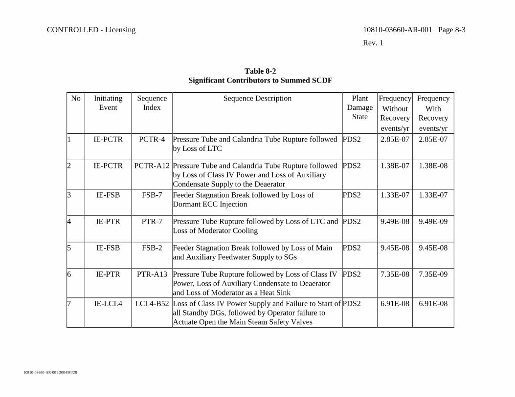
CONTROLLED - Licensing 10810-03660-AR-001 Page 8-3
Rev. 1
10810-03660-AR-001 2004/01/28
Table 8-2 Significant Contributors to Summed SCDF
No Initiating Event
SequenceIndex
Sequence Description Plant Damage
State
FrequencyWithout Recoveryevents/yr
Frequency With
Recovery events/yr
1 IE-PCTR PCTR-4 Pressure Tube and Calandria Tube Rupture followed by Loss of LTC
PDS2 2.85E-07 2.85E-07
2 IE-PCTR PCTR-A12 Pressure Tube and Calandria Tube Rupture followed by Loss of Class IV Power and Loss of Auxiliary Condensate Supply to the Deaerator
PDS2 1.38E-07 1.38E-08
3 IE-FSB FSB-7 Feeder Stagnation Break followed by Loss of Dormant ECC Injection
PDS2 1.33E-07 1.33E-07
4 IE-PTR PTR-7 Pressure Tube Rupture followed by Loss of LTC and Loss of Moderator Cooling
PDS2 9.49E-08 9.49E-09
5 IE-FSB FSB-2 Feeder Stagnation Break followed by Loss of Main and Auxiliary Feedwater Supply to SGs
PDS2 9.45E-08 9.45E-08
6 IE-PTR PTR-A13 Pressure Tube Rupture followed by Loss of Class IV Power, Loss of Auxiliary Condensate to Deaerator and Loss of Moderator as a Heat Sink
PDS2 7.35E-08 7.35E-09
7 IE-LCL4 LCL4-B52 Loss of Class IV Power Supply and Failure to Start of all Standby DGs, followed by Operator failure to Actuate Open the Main Steam Safety Valves
PDS2 6.91E-08 6.91E-08
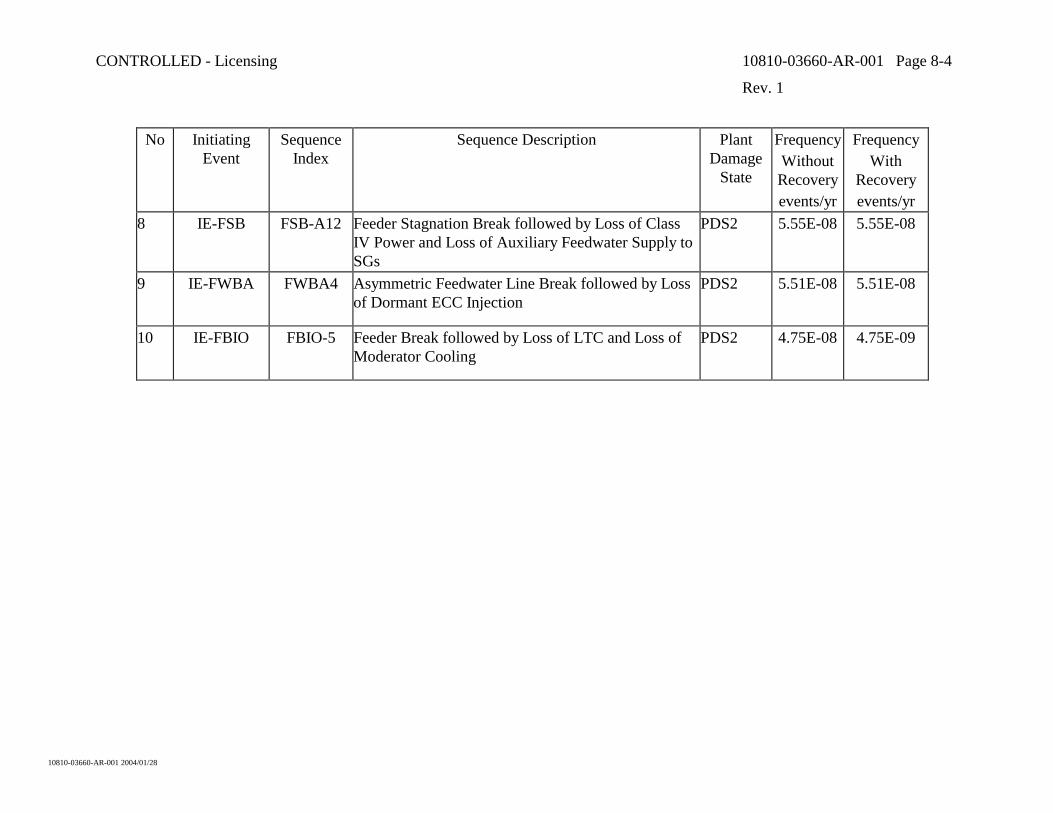
CONTROLLED - Licensing 10810-03660-AR-001 Page 8-4
Rev. 1
10810-03660-AR-001 2004/01/28
No Initiating Event
SequenceIndex
Sequence Description Plant Damage
State
FrequencyWithout Recoveryevents/yr
Frequency With
Recovery events/yr
8 IE-FSB FSB-A12 Feeder Stagnation Break followed by Loss of Class IV Power and Loss of Auxiliary Feedwater Supply to SGs
PDS2 5.55E-08 5.55E-08
9 IE-FWBA FWBA4 Asymmetric Feedwater Line Break followed by Loss of Dormant ECC Injection
PDS2 5.51E-08 5.51E-08
10 IE-FBIO FBIO-5 Feeder Break followed by Loss of LTC and Loss of Moderator Cooling
PDS2 4.75E-08 4.75E-09
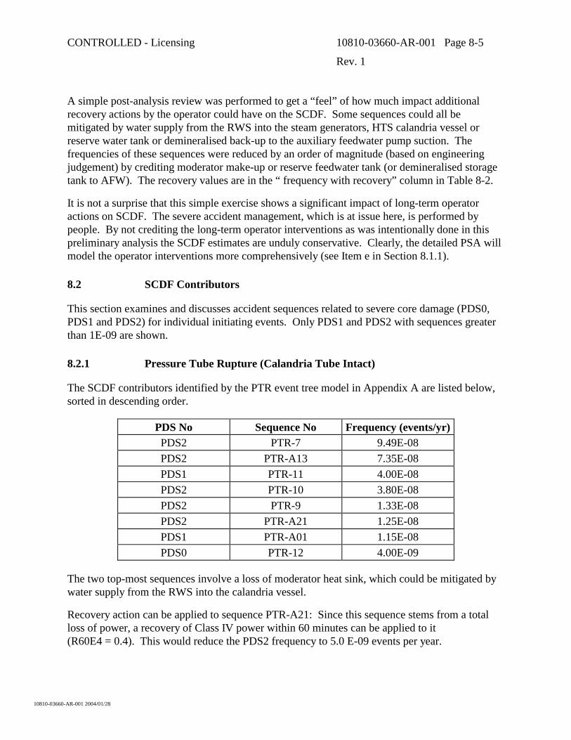
CONTROLLED - Licensing 10810-03660-AR-001 Page 8-5
Rev. 1
10810-03660-AR-001 2004/01/28
A simple post-analysis review was performed to get a “feel” of how much impact additional recovery actions by the operator could have on the SCDF. Some sequences could all be mitigated by water supply from the RWS into the steam generators, HTS calandria vessel or reserve water tank or demineralised back-up to the auxiliary feedwater pump suction. The frequencies of these sequences were reduced by an order of magnitude (based on engineering judgement) by crediting moderator make-up or reserve feedwater tank (or demineralised storage tank to AFW). The recovery values are in the “ frequency with recovery” column in Table 8-2.
It is not a surprise that this simple exercise shows a significant impact of long-term operator actions on SCDF. The severe accident management, which is at issue here, is performed by people. By not crediting the long-term operator interventions as was intentionally done in this preliminary analysis the SCDF estimates are unduly conservative. Clearly, the detailed PSA will model the operator interventions more comprehensively (see Item e in Section 8.1.1).
8.2 SCDF Contributors
This section examines and discusses accident sequences related to severe core damage (PDS0, PDS1 and PDS2) for individual initiating events. Only PDS1 and PDS2 with sequences greater than 1E-09 are shown.
8.2.1 Pressure Tube Rupture (Calandria Tube Intact)
The SCDF contributors identified by the PTR event tree model in Appendix A are listed below, sorted in descending order.
PDS No Sequence No Frequency (events/yr) PDS2 PTR-7 9.49E-08 PDS2 PTR-A13 7.35E-08 PDS1 PTR-11 4.00E-08 PDS2 PTR-10 3.80E-08 PDS2 PTR-9 1.33E-08 PDS2 PTR-A21 1.25E-08 PDS1 PTR-A01 1.15E-08 PDS0 PTR-12 4.00E-09
The two top-most sequences involve a loss of moderator heat sink, which could be mitigated by water supply from the RWS into the calandria vessel.
Recovery action can be applied to sequence PTR-A21: Since this sequence stems from a total loss of power, a recovery of Class IV power within 60 minutes can be applied to it (R60E4 = 0.4). This would reduce the PDS2 frequency to 5.0 E-09 events per year.
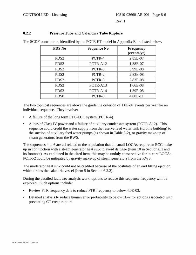
CONTROLLED - Licensing 10810-03660-AR-001 Page 8-6
Rev. 1
10810-03660-AR-001 2004/01/28
8.2.2 Pressure Tube and Calandria Tube Rupture
The SCDF contributors identified by the PCTR ET model in Appendix B are listed below.
PDS No Sequence No Frequency (events/yr)
PDS2 PCTR-4 2.85E-07 PDS2 PCTR-A12 1.38E-07 PDS2 PCTR-5 3.99E-08 PDS2 PCTR-2 2.83E-08 PDS2 PCTR-3 2.83E-08 PDS2 PCTR-A13 1.66E-08 PDS2 PCTR-A14 1.39E-08 PDS0 PCTR-8 4.00E-11
The two topmost sequences are above the guideline criterion of 1.0E-07 events per year for an individual sequence. They involve:
• A failure of the long term LTC-ECC system (PCTR-4)
• A loss of Class IV power and a failure of auxiliary condensate system (PCTR-A12). This sequence could credit the water supply from the reserve feed water tank (turbine building) to the suction of auxiliary feed water pumps (as shown in Table 8-2), or gravity make-up of steam generators from the RWS.
The sequences 4 to 6 are all related to the stipulation that all small LOCAs require an ECC make-up in conjunction with a steam generator heat sink to avoid damage (Item 10 in Section 6.1 and its footnote) As explained in the cited item, this may be unduly conservative for in-core LOCAs. PCTR-2 could be mitigated by gravity make-up of steam generators from the RWS.
The moderator heat sink could not be credited because of the postulate of an end fitting ejection, which drains the calandria vessel (Item 5 in Section 6.2.2).
During the detailed fault tree analysis work, options to reduce this sequence frequency will be explored. Such options include:
• Review PTR frequency data to reduce PTR frequency to below 4.0E-03.
• Detailed analysis to reduce human error probability to below 1E-2 for actions associated with preventing CT creep rupture.
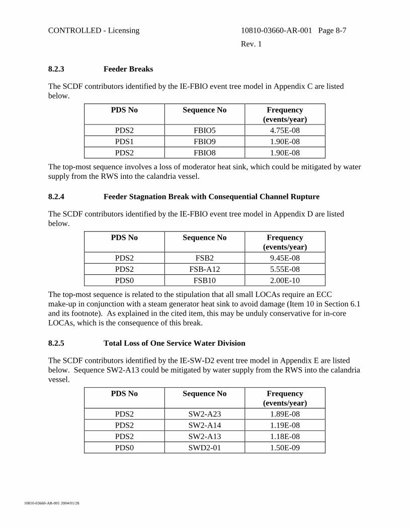
CONTROLLED - Licensing 10810-03660-AR-001 Page 8-7
Rev. 1
10810-03660-AR-001 2004/01/28
8.2.3 Feeder Breaks
The SCDF contributors identified by the IE-FBIO event tree model in Appendix C are listed below.
PDS No Sequence No Frequency (events/year)
PDS2 FBIO5 4.75E-08 PDS1 FBIO9 1.90E-08 PDS2 FBIO8 1.90E-08
The top-most sequence involves a loss of moderator heat sink, which could be mitigated by water supply from the RWS into the calandria vessel.
8.2.4 Feeder Stagnation Break with Consequential Channel Rupture
The SCDF contributors identified by the IE-FBIO event tree model in Appendix D are listed below.
PDS No Sequence No Frequency (events/year)
PDS2 FSB2 9.45E-08 PDS2 FSB-A12 5.55E-08 PDS0 FSB10 2.00E-10
The top-most sequence is related to the stipulation that all small LOCAs require an ECC make-up in conjunction with a steam generator heat sink to avoid damage (Item 10 in Section 6.1 and its footnote). As explained in the cited item, this may be unduly conservative for in-core LOCAs, which is the consequence of this break.
8.2.5 Total Loss of One Service Water Division
The SCDF contributors identified by the IE-SW-D2 event tree model in Appendix E are listed below. Sequence SW2-A13 could be mitigated by water supply from the RWS into the calandria vessel.
PDS No Sequence No Frequency (events/year)
PDS2 SW2-A23 1.89E-08 PDS2 SW2-A14 1.19E-08 PDS2 SW2-A13 1.18E-08 PDS0 SWD2-01 1.50E-09
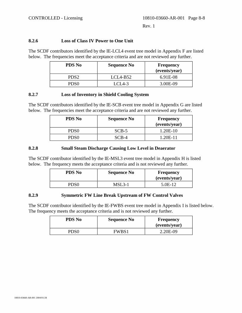
CONTROLLED - Licensing 10810-03660-AR-001 Page 8-8
Rev. 1
10810-03660-AR-001 2004/01/28
8.2.6 Loss of Class IV Power to One Unit
The SCDF contributors identified by the IE-LCL4 event tree model in Appendix F are listed below. The frequencies meet the acceptance criteria and are not reviewed any further.
PDS No Sequence No Frequency (events/year)
PDS2 LCL4-B52 6.91E-08 PDS0 LCL4-3 3.00E-09
8.2.7 Loss of Inventory in Shield Cooling System
The SCDF contributors identified by the IE-SCB event tree model in Appendix G are listed below. The frequencies meet the acceptance criteria and are not reviewed any further.
PDS No Sequence No Frequency (events/year)
PDS0 SCB-5 1.20E-10 PDS0 SCB-4 1.20E-11
8.2.8 Small Steam Discharge Causing Low Level in Deaerator
The SCDF contributor identified by the IE-MSL3 event tree model in Appendix H is listed below. The frequency meets the acceptance criteria and is not reviewed any further.
PDS No Sequence No Frequency (events/year)
PDS0 MSL3-1 5.0E-12
8.2.9 Symmetric FW Line Break Upstream of FW Control Valves
The SCDF contributor identified by the IE-FWBS event tree model in Appendix I is listed below. The frequency meets the acceptance criteria and is not reviewed any further.
PDS No Sequence No Frequency (events/year)
PDS0 FWBS1 2.20E-09
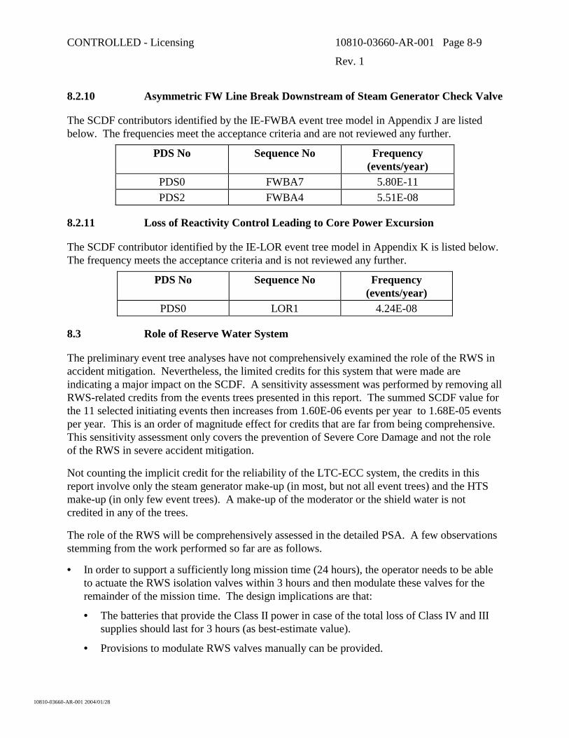
CONTROLLED - Licensing 10810-03660-AR-001 Page 8-9
Rev. 1
10810-03660-AR-001 2004/01/28
8.2.10 Asymmetric FW Line Break Downstream of Steam Generator Check Valve
The SCDF contributors identified by the IE-FWBA event tree model in Appendix J are listed below. The frequencies meet the acceptance criteria and are not reviewed any further.
PDS No Sequence No Frequency (events/year)
PDS0 FWBA7 5.80E-11 PDS2 FWBA4 5.51E-08
8.2.11 Loss of Reactivity Control Leading to Core Power Excursion
The SCDF contributor identified by the IE-LOR event tree model in Appendix K is listed below. The frequency meets the acceptance criteria and is not reviewed any further.
PDS No Sequence No Frequency (events/year)
PDS0 LOR1 4.24E-08
8.3 Role of Reserve Water System
The preliminary event tree analyses have not comprehensively examined the role of the RWS in accident mitigation. Nevertheless, the limited credits for this system that were made are indicating a major impact on the SCDF. A sensitivity assessment was performed by removing all RWS-related credits from the events trees presented in this report. The summed SCDF value for the 11 selected initiating events then increases from 1.60E-06 events per year to 1.68E-05 events per year. This is an order of magnitude effect for credits that are far from being comprehensive. This sensitivity assessment only covers the prevention of Severe Core Damage and not the role of the RWS in severe accident mitigation.
Not counting the implicit credit for the reliability of the LTC-ECC system, the credits in this report involve only the steam generator make-up (in most, but not all event trees) and the HTS make-up (in only few event trees). A make-up of the moderator or the shield water is not credited in any of the trees.
The role of the RWS will be comprehensively assessed in the detailed PSA. A few observations stemming from the work performed so far are as follows.
• In order to support a sufficiently long mission time (24 hours), the operator needs to be able to actuate the RWS isolation valves within 3 hours and then modulate these valves for the remainder of the mission time. The design implications are that:
• The batteries that provide the Class II power in case of the total loss of Class IV and III supplies should last for 3 hours (as best-estimate value).
• Provisions to modulate RWS valves manually can be provided.
CONTROLLED - Licensing 10810-03660-AR-001 Page 8-10
Rev. 1
10810-03660-AR-001 2004/01/28
8.4 Key PSA Assumptions
The event tree analysis utilized many assumptions related to design and plant response. As part of the ACR detailed design development process, these assumptions are required to be supported by analysis and/or equipment supplier’s test records as appropriate. A list of key PSA support assumptions and risk items is provided below:
• A connection from reserve feed water tank (turbine building) or demineralised water storage tank to the auxiliary feed water pumps suction header is important. This connection will enable the auxiliary feed water pump to maintain supply to the steam generators in the event of a loss of auxiliary condensate pump.
• A reliable, automatic closure of the auxiliary feed water level control valves when discrepancy between the two steam generator levels is sensed is important to crediting the auxiliary feed water in certain accidents.
• In order to defend calandria tube failure probability following a pressure tube rupture, the R&D program needs to demonstrate that the calandria tube will survive all relevant loading conditions. The program also needs to demonstrate that the calandria tube has a high creep rupture resistance. The latter is the ability of the calandria tube to withstand the elevated pressure and temperature environments after a pressure tube failure for long enough time so that operator action can be relied upon to reduce the HTS pressure. To afford high reliability credit for this operator action, the calandria tube needs to survive for about 2 hours or longer.
• Operator plays a crucial role following shield cooling accidents. For highly reliable actions, long times need to be available for manual actions. The current assumption based on CANDU-9 analysis is that 8 hours is available before the HTS pressure boundary, or any other boundary that holds water, could be threatened following a loss of shield water inventory. Analyses need to ascertain that long times are available as well.
• Although the HT pumps are not formally environmentally qualified, it is assumed (as best estimate) that at least one pump can run for up to 60 minutes after a feed water line break in the reactor building. This assumption is reasonably supported by the fact that the HTS pumps are not exposed to cavitation conditions (HTS remains pressurized and it is re-filled by emergency coolant) and that the discharge from the broken line will not directly impact the pumps. As far as practicable, the layout of the piping needs to minimize a harsh environment around the HT pumps.
CONTROLLED - Licensing 10810-03660-AR-001 Page 9-1
Rev. 1
10810-03660-AR-001 2004/01/28
9. CONCLUSIONS
This preliminary event tree analysis report has provided early inputs to the design teams regarding the reliability/unavailability requirements on the ACR systems that are used for accident mitigation as well as feedbacks on some of the system performance requirements. Completion of this design assist event tree analysis is an important milestone in that it has provided insights into adequacy of the safety design to help meet the acceptance criteria. The role of PSA is ongoing. These reliability targets are intended to guide the designers in the development of the design.
The analyses in this report identify which internal event sequences will likely dominate the SCDF in the ACR and which elements of the dominant sequences contribute most to the SCDF. Conservative simplifications are employed in this report, which will be reviewed, updated and removed during the detailed PSA.
This preliminary analysis provides a high degree of confidence that the design target on the summed SCDF for all internal and external events can be met.
CONTROLLED - Licensing 10810-03660-AR-001 Page 10-1
Rev. 1
10810-03660-AR-001 2004/01/28
10. REFERENCES
[1] AECL – “Licensing Basis for Advanced CANDU Reactor”, 108-00580-LBD-001, Rev. 0, 2002 July.
[2] AECL – ACR Technical Outline, 10810-01372-TED-001, Rev. 1, 2002 August.
[3] AECL - Probabilistic Safety Assessment Methodology , 108-03660-AB-001, Rev. 1, 2003 July.
[4] Science Applications International Corporation - “ETA-II Users Manual For Version 2.1”, now DS&S) 1992 August.
[5] US NRC, Accident Sequence Evaluation Program Human reliability Analysis Procedure, NUREG/CR-4772, Prepared for the US NRC by Sandia National Laboratories (SAND86-1996), Albuquerque, NM, February 1987.
[6] AECL – “Environmental Qualification”, 108-03650-SDG-003, Rev. 1, October 2002.
[7] CNSC - Safety Analysis of CANDU Nuclear Power Plant – Draft Regulatory Guide C-006, Rev. 1, 1999 September.

CONTROLLED - Licensing 10810-03660-AR-001 Page A-1
Rev. 1
10810-03660-AR-001 2004/01/28
Appendix A
Event Tree for Pressure Tube Rupture
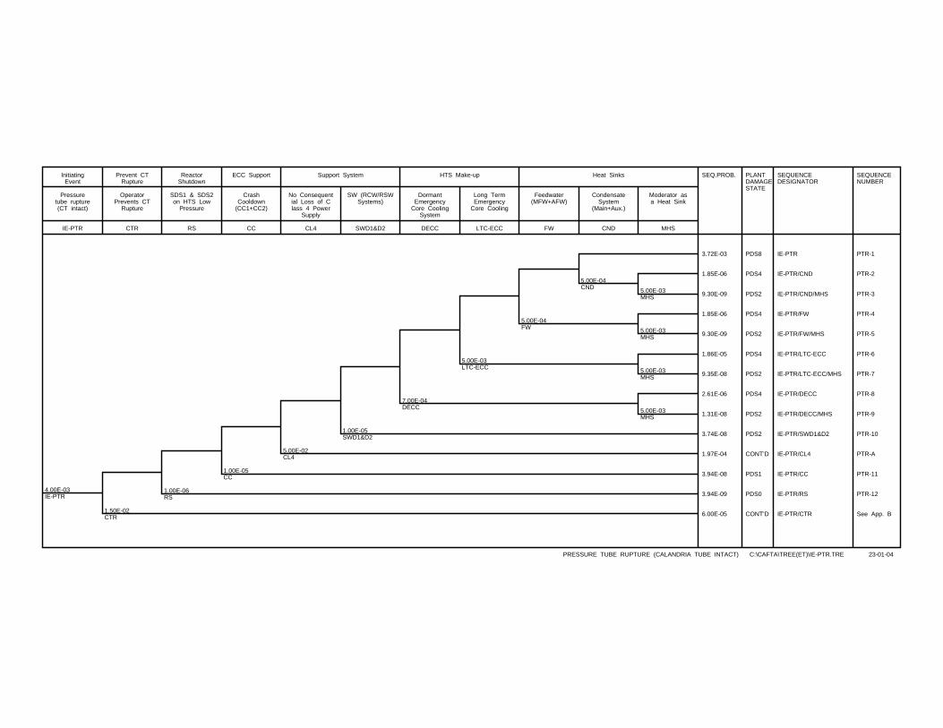
4.00E-03IE-PTR
1.50E-02CTR
1.00E-06RS
1.00E-05CC
5.00E-02CL4
1.00E-05SWD1&D2
7.00E-04DECC
5.00E-03LTC-ECC
5.00E-04FW
5.00E-04CND 5.00E-03
MHS
5.00E-03MHS
5.00E-03MHS
5.00E-03MHS
SEQ.PROB. PLANTDAMAGESTATE
SEQUENCEDESIGNATOR
SEQUENCENUMBER
3.72E-03 PDS8 IE-PTR PTR-1
1.85E-06 PDS4 IE-PTR/CND PTR-2
9.30E-09 PDS2 IE-PTR/CND/MHS PTR-3
1.85E-06 PDS4 IE-PTR/FW PTR-4
9.30E-09 PDS2 IE-PTR/FW/MHS PTR-5
1.86E-05 PDS4 IE-PTR/LTC-ECC PTR-6
9.35E-08 PDS2 IE-PTR/LTC-ECC/MHS PTR-7
2.61E-06 PDS4 IE-PTR/DECC PTR-8
1.31E-08 PDS2 IE-PTR/DECC/MHS PTR-9
3.74E-08 PDS2 IE-PTR/SWD1&D2 PTR-10
1.97E-04 CONT’D IE-PTR/CL4 PTR-A
3.94E-08 PDS1 IE-PTR/CC PTR-11
3.94E-09 PDS0 IE-PTR/RS PTR-12
6.00E-05 CONT’D IE-PTR/CTR See App. B
IE-PTR
Pressuretube rupture(CT intact)
InitiatingEvent
CTR
OperatorPrevents CT
Rupture
Prevent CTRupture
RS
SDS1 & SDS2on HTS Low
Pressure
ReactorShutdown
CC
CrashCooldown
(CC1+CC2)
ECC Support
CL4
No Consequential Loss of Class 4 Power
Supply
SWD1&D2
SW (RCW/RSWSystems)
Support System
DECC
DormantEmergency
Core CoolingSystem
LTC-ECC
Long TermEmergency
Core Cooling
HTS Make-up
FW
Feedwater(MFW+AFW)
CND
CondensateSystem
(Main+Aux.)
MHS
Moderator asa Heat Sink
Heat Sinks
PRESSURE TUBE RUPTURE (CALANDRIA TUBE INTACT) C:\CAFTA\TREE(ET)\IE-PTR.TRE 23-01-04
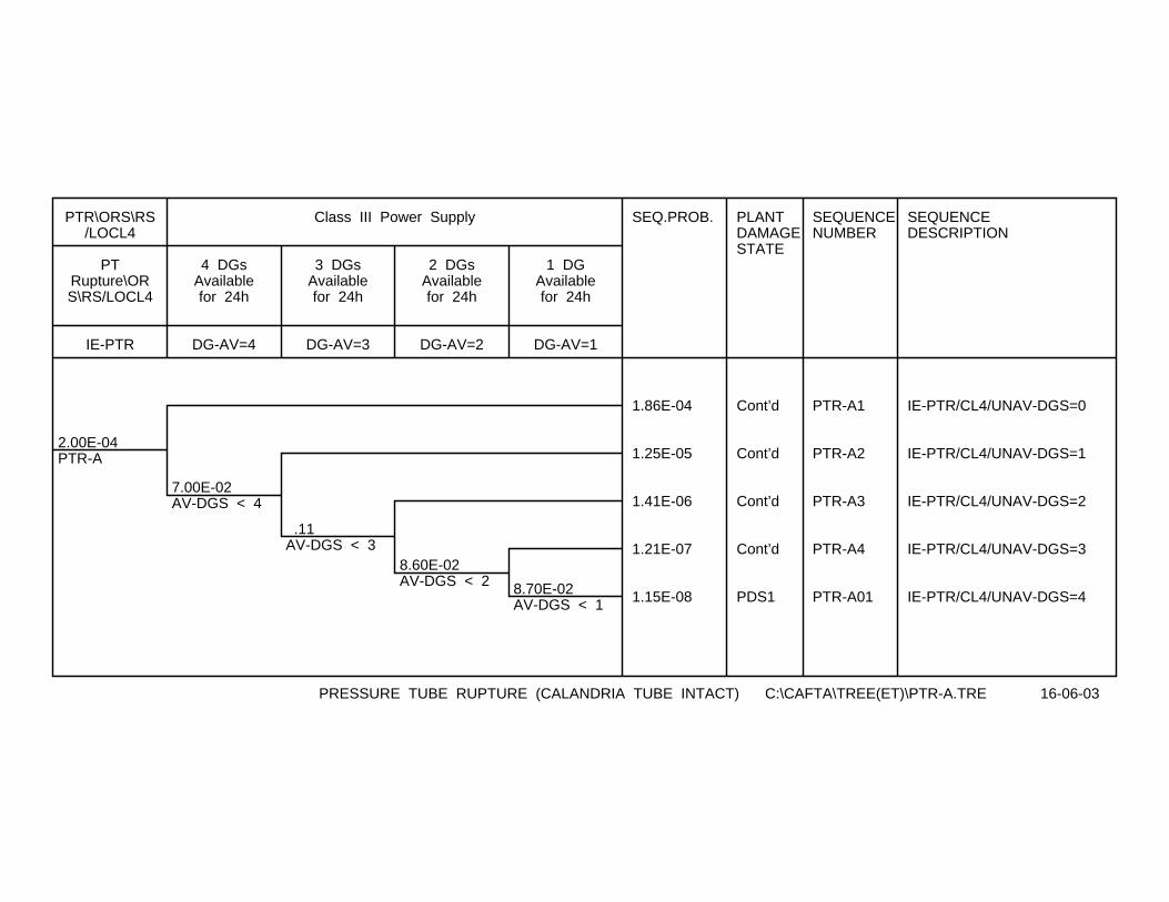
2.00E-04PTR-A
7.00E-02AV-DGS < 4
.11AV-DGS < 3
8.60E-02AV-DGS < 2 8.70E-02
AV-DGS < 1
SEQ.PROB. PLANTDAMAGESTATE
SEQUENCENUMBER
SEQUENCEDESCRIPTION
1.86E-04 Cont’d PTR-A1 IE-PTR/CL4/UNAV-DGS=0
1.25E-05 Cont’d PTR-A2 IE-PTR/CL4/UNAV-DGS=1
1.41E-06 Cont’d PTR-A3 IE-PTR/CL4/UNAV-DGS=2
1.21E-07 Cont’d PTR-A4 IE-PTR/CL4/UNAV-DGS=3
1.15E-08 PDS1 PTR-A01 IE-PTR/CL4/UNAV-DGS=4
IE-PTR
PTRupture\ORS\RS/LOCL4
PTR\ORS\RS/LOCL4
DG-AV=4
4 DGsAvailablefor 24h
DG-AV=3
3 DGsAvailablefor 24h
DG-AV=2
2 DGsAvailablefor 24h
DG-AV=1
1 DGAvailablefor 24h
Class III Power Supply
PRESSURE TUBE RUPTURE (CALANDRIA TUBE INTACT) C:\CAFTA\TREE(ET)\PTR-A.TRE 16-06-03
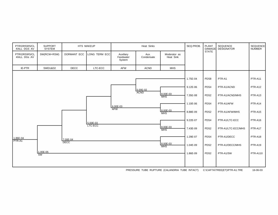
1.86E-04PTR-A1
1.00E-05SW
7.00E-04DECC
5.00E-03LTC-ECC
6.00E-03AFW
5.00E-02ACND 8.00E-03
MHS
8.00E-03MHS
8.00E-03MHS
8.00E-03MHS
SEQ.PROB. PLANTDAMAGESTATE
SEQUENCEDESIGNATOR
SEQUENCENUMBER
1.75E-04 PDS8 PTR-A1 PTR-A11
9.12E-06 PDS4 PTR-A1/ACND PTR-A12
7.35E-08 PDS2 PTR-A1/ACND/MHS PTR-A13
1.10E-06 PDS4 PTR-A1/AFW PTR-A14
8.88E-09 PDS2 PTR-A1/AFW/MHS PTR-A15
9.22E-07 PDS4 PTR-A1/LTC-ECC PTR-A16
7.43E-09 PDS2 PTR-A1/LTC-ECC/MHS PTR-A17
1.29E-07 PDS4 PTR-A1/DECC PTR-A18
1.04E-09 PDS2 PTR-A1/DECC/MHS PTR-A19
1.86E-09 PDS2 PTR-A1/SW PTR-A110
IE-PTR
PTR\ORS\RS/CL4\ALL DGs AV
PTR\ORS\RS/CL4\ALL DGS AV
SWD1&D2
SW(RCW+RSW)
SUPPORTSYSTEM
DECC
DORMANT ECC
LTC-ECC
LONG TERM ECC
HTS MAKEUP
AFW
AuxiliaryFeedwater
System
ACND
Aux.Condensate
MHS
Moderator asHeat Sink
Heat Sinks
PRESSURE TUBE RUPTURE (CALANDRIA TUBE INTACT) C:\CAFTA\TREE(ET)\PTR-A1.TRE 16-06-03
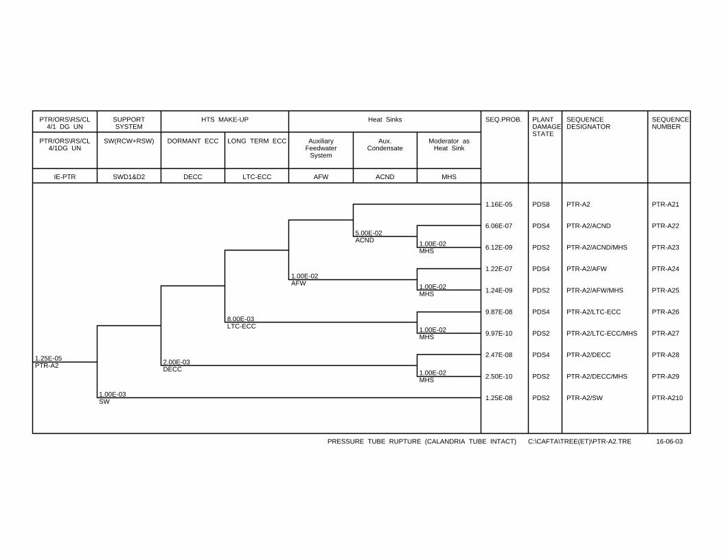
1.25E-05PTR-A2
1.00E-03SW
2.00E-03DECC
8.00E-03LTC-ECC
1.00E-02AFW
5.00E-02ACND 1.00E-02
MHS
1.00E-02MHS
1.00E-02MHS
1.00E-02MHS
SEQ.PROB. PLANTDAMAGESTATE
SEQUENCEDESIGNATOR
SEQUENCENUMBER
1.16E-05 PDS8 PTR-A2 PTR-A21
6.06E-07 PDS4 PTR-A2/ACND PTR-A22
6.12E-09 PDS2 PTR-A2/ACND/MHS PTR-A23
1.22E-07 PDS4 PTR-A2/AFW PTR-A24
1.24E-09 PDS2 PTR-A2/AFW/MHS PTR-A25
9.87E-08 PDS4 PTR-A2/LTC-ECC PTR-A26
9.97E-10 PDS2 PTR-A2/LTC-ECC/MHS PTR-A27
2.47E-08 PDS4 PTR-A2/DECC PTR-A28
2.50E-10 PDS2 PTR-A2/DECC/MHS PTR-A29
1.25E-08 PDS2 PTR-A2/SW PTR-A210
IE-PTR
PTR/ORS\RS/CL4/1DG UN
PTR/ORS\RS/CL4/1 DG UN
SWD1&D2
SW(RCW+RSW)
SUPPORTSYSTEM
DECC
DORMANT ECC
LTC-ECC
LONG TERM ECC
HTS MAKE-UP
AFW
AuxiliaryFeedwater
System
ACND
Aux.Condensate
MHS
Moderator asHeat Sink
Heat Sinks
PRESSURE TUBE RUPTURE (CALANDRIA TUBE INTACT) C:\CAFTA\TREE(ET)\PTR-A2.TRE 16-06-03
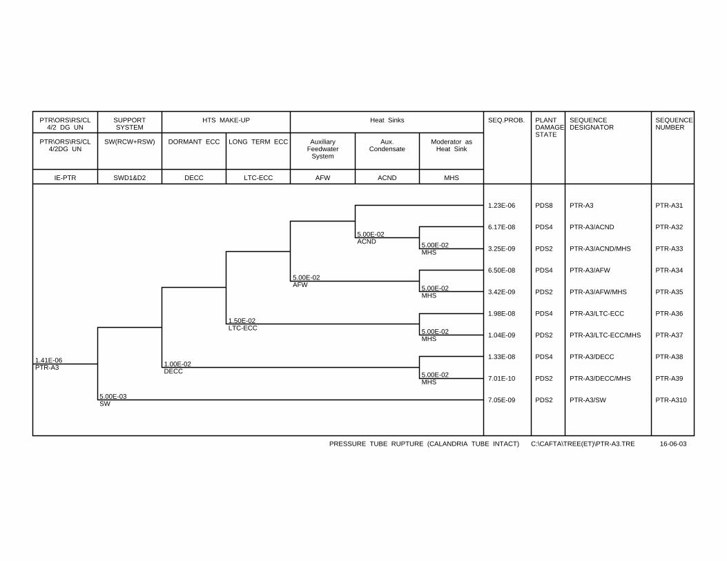
1.41E-06PTR-A3
5.00E-03SW
1.00E-02DECC
1.50E-02LTC-ECC
5.00E-02AFW
5.00E-02ACND 5.00E-02
MHS
5.00E-02MHS
5.00E-02MHS
5.00E-02MHS
SEQ.PROB. PLANTDAMAGESTATE
SEQUENCEDESIGNATOR
SEQUENCENUMBER
1.23E-06 PDS8 PTR-A3 PTR-A31
6.17E-08 PDS4 PTR-A3/ACND PTR-A32
3.25E-09 PDS2 PTR-A3/ACND/MHS PTR-A33
6.50E-08 PDS4 PTR-A3/AFW PTR-A34
3.42E-09 PDS2 PTR-A3/AFW/MHS PTR-A35
1.98E-08 PDS4 PTR-A3/LTC-ECC PTR-A36
1.04E-09 PDS2 PTR-A3/LTC-ECC/MHS PTR-A37
1.33E-08 PDS4 PTR-A3/DECC PTR-A38
7.01E-10 PDS2 PTR-A3/DECC/MHS PTR-A39
7.05E-09 PDS2 PTR-A3/SW PTR-A310
IE-PTR
PTR\ORS\RS/CL4/2DG UN
PTR\ORS\RS/CL4/2 DG UN
SWD1&D2
SW(RCW+RSW)
SUPPORTSYSTEM
DECC
DORMANT ECC
LTC-ECC
LONG TERM ECC
HTS MAKE-UP
AFW
AuxiliaryFeedwater
System
ACND
Aux.Condensate
MHS
Moderator asHeat Sink
Heat Sinks
PRESSURE TUBE RUPTURE (CALANDRIA TUBE INTACT) C:\CAFTA\TREE(ET)\PTR-A3.TRE 16-06-03
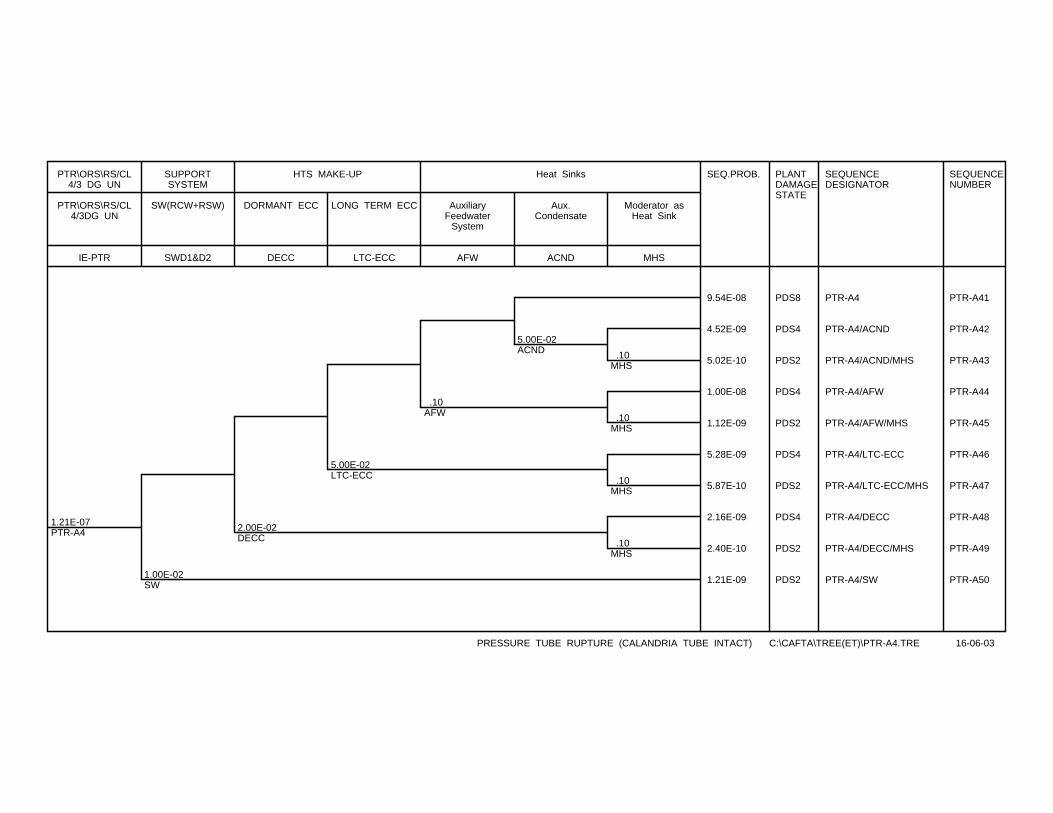
1.21E-07PTR-A4
1.00E-02SW
2.00E-02DECC
5.00E-02LTC-ECC
.10AFW
5.00E-02ACND .10
MHS
.10MHS
.10MHS
.10MHS
SEQ.PROB. PLANTDAMAGESTATE
SEQUENCEDESIGNATOR
SEQUENCENUMBER
9.54E-08 PDS8 PTR-A4 PTR-A41
4.52E-09 PDS4 PTR-A4/ACND PTR-A42
5.02E-10 PDS2 PTR-A4/ACND/MHS PTR-A43
1.00E-08 PDS4 PTR-A4/AFW PTR-A44
1.12E-09 PDS2 PTR-A4/AFW/MHS PTR-A45
5.28E-09 PDS4 PTR-A4/LTC-ECC PTR-A46
5.87E-10 PDS2 PTR-A4/LTC-ECC/MHS PTR-A47
2.16E-09 PDS4 PTR-A4/DECC PTR-A48
2.40E-10 PDS2 PTR-A4/DECC/MHS PTR-A49
1.21E-09 PDS2 PTR-A4/SW PTR-A50
IE-PTR
PTR\ORS\RS/CL4/3DG UN
PTR\ORS\RS/CL4/3 DG UN
SWD1&D2
SW(RCW+RSW)
SUPPORTSYSTEM
DECC
DORMANT ECC
LTC-ECC
LONG TERM ECC
HTS MAKE-UP
AFW
AuxiliaryFeedwater
System
ACND
Aux.Condensate
MHS
Moderator asHeat Sink
Heat Sinks
PRESSURE TUBE RUPTURE (CALANDRIA TUBE INTACT) C:\CAFTA\TREE(ET)\PTR-A4.TRE 16-06-03
CONTROLLED - Licensing 10810-03660-AR-001 Page B-1
Rev. 1
10810-03660-AR-001 2004/01/28
Appendix B
Event Tree for Pressure Tube and Calandria Tube Rupture
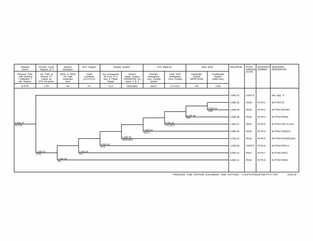
4.00E-03IE-PTR
1.50E-02CTR
1.00E-06RS
1.00E-05CC
5.00E-02CL4
1.00E-05SWD1&D2
7.00E-04DECC
5.00E-03LTC-ECC
5.00E-04FW
5.00E-04CND
SEQ.PROB. PLANTDAMAGESTATE
SEQUENCENUMBER
SEQUENCEDESIGNATOR
3.94E-03 CONT’D See App. A
5.66E-05 PDS8 PCTR-1 IE-PTR/CTR
2.83E-08 PDS2 PCTR-2 IE-PTR/CTR/CND
2.83E-08 PDS2 PCTR-3 IE-PTR/CTR/FW
2.85E-07 PDS2 PCTR-4 IE-PTR/CTR/LTC-ECC
3.99E-08 PDS2 PCTR-5 IE-PTR/CTR/DECC
5.70E-10 PDS2 PCTR-6 IE-PTR/CTR/SWD1&D2
3.00E-06 CONT’D PCTR-A IE-PTR/CTR/CL4
6.00E-10 PDS1 PCTR-7 IE-PTR/CTR/CC
6.00E-11 PDS0 PCTR-8 IE-PTR/CTR/RS
IE-PTR
Pressure Tube with Eventual Calandria Tube Rupture
InitiatingEvent
CTR
Op. Fails toPrevent CTFailure by
HTS De-press.
Prevent Creep Rupture of C
RS
SDS1 & SDS2On High
moderatorlevel
ReactorShutdown
CC
CrashCooldown
(CC1+CC2)
ECC Support
CL4
No Consequential Loss of Class 4 Power
Supply
SWD1&D2
ServiceWater System
(RSW/RCW) Divisions 1 & 2
Support System
DECC
DormantEmergency
Core CoolingSystem
LTC-ECC
Long TermEmergency
Core Cooling
HTS Make-up
FW
FeedwaterSystem
(MFW+AFW)
CND
CondensateSystem
(Main+Aux)
Heat Sinks
PRESSURE TUBE RUPTURE (CALANDRIA TUBE RUPTURE) C:\CAFTA\TREE(ET)\IE-PT-CT.TRE 23-01-04
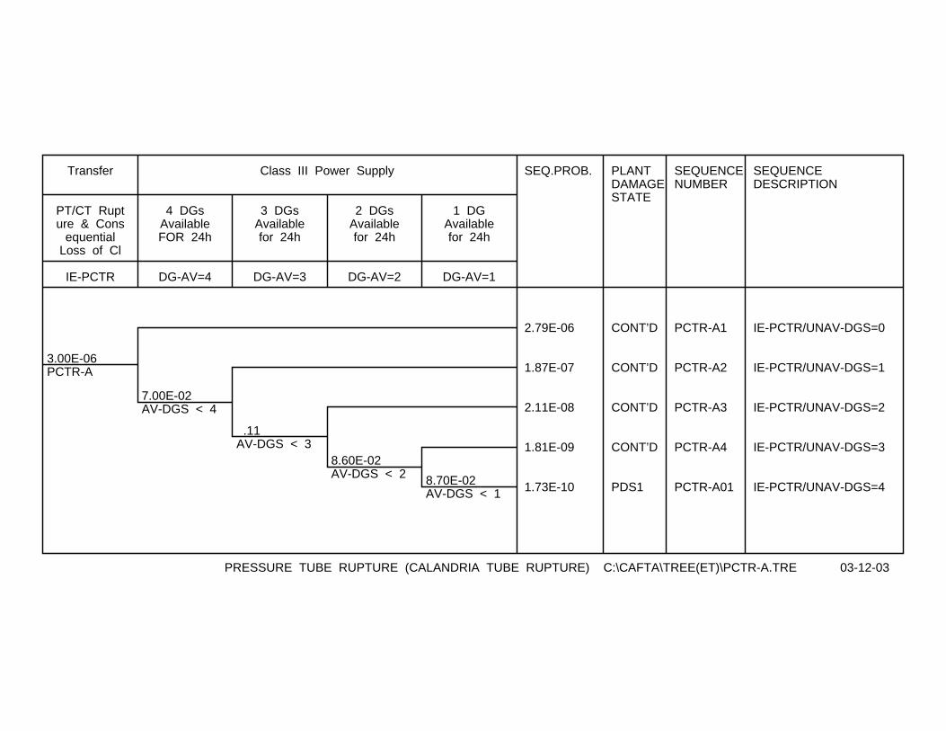
3.00E-06PCTR-A
7.00E-02AV-DGS < 4
.11AV-DGS < 3
8.60E-02AV-DGS < 2 8.70E-02
AV-DGS < 1
SEQ.PROB. PLANTDAMAGESTATE
SEQUENCENUMBER
SEQUENCEDESCRIPTION
2.79E-06 CONT’D PCTR-A1 IE-PCTR/UNAV-DGS=0
1.87E-07 CONT’D PCTR-A2 IE-PCTR/UNAV-DGS=1
2.11E-08 CONT’D PCTR-A3 IE-PCTR/UNAV-DGS=2
1.81E-09 CONT’D PCTR-A4 IE-PCTR/UNAV-DGS=3
1.73E-10 PDS1 PCTR-A01 IE-PCTR/UNAV-DGS=4
IE-PCTR
PT/CT Rupture & Cons
equentialLoss of Cl
Transfer
DG-AV=4
4 DGsAvailableFOR 24h
DG-AV=3
3 DGsAvailablefor 24h
DG-AV=2
2 DGsAvailablefor 24h
DG-AV=1
1 DGAvailablefor 24h
Class III Power Supply
PRESSURE TUBE RUPTURE (CALANDRIA TUBE RUPTURE) C:\CAFTA\TREE(ET)\PCTR-A.TRE 03-12-03
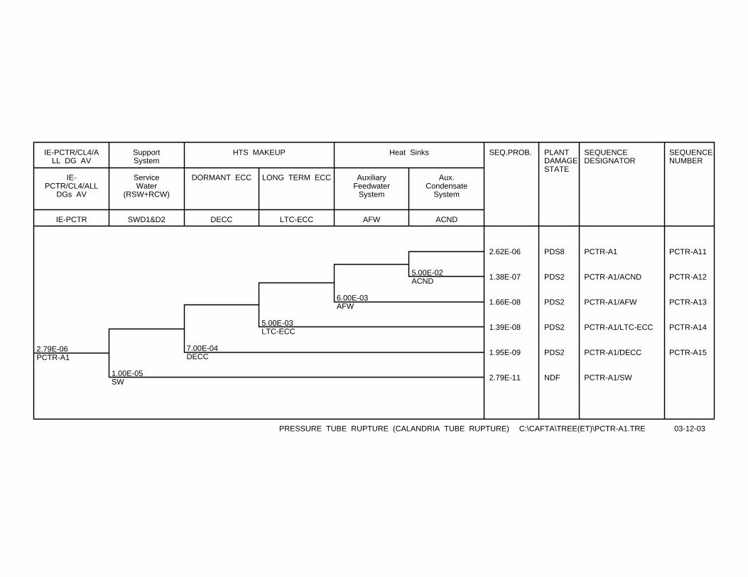
2.79E-06PCTR-A1
1.00E-05SW
7.00E-04DECC
5.00E-03LTC-ECC
6.00E-03AFW
5.00E-02ACND
SEQ.PROB. PLANTDAMAGESTATE
SEQUENCEDESIGNATOR
SEQUENCENUMBER
2.62E-06 PDS8 PCTR-A1 PCTR-A11
1.38E-07 PDS2 PCTR-A1/ACND PCTR-A12
1.66E-08 PDS2 PCTR-A1/AFW PCTR-A13
1.39E-08 PDS2 PCTR-A1/LTC-ECC PCTR-A14
1.95E-09 PDS2 PCTR-A1/DECC PCTR-A15
2.79E-11 NDF PCTR-A1/SW
IE-PCTR
IE-PCTR/CL4/ALL
DGs AV
IE-PCTR/CL4/ALL DG AV
SWD1&D2
ServiceWater
(RSW+RCW)
SupportSystem
DECC
DORMANT ECC
LTC-ECC
LONG TERM ECC
HTS MAKEUP
AFW
AuxiliaryFeedwater
System
ACND
Aux.Condensate
System
Heat Sinks
PRESSURE TUBE RUPTURE (CALANDRIA TUBE RUPTURE) C:\CAFTA\TREE(ET)\PCTR-A1.TRE 03-12-03
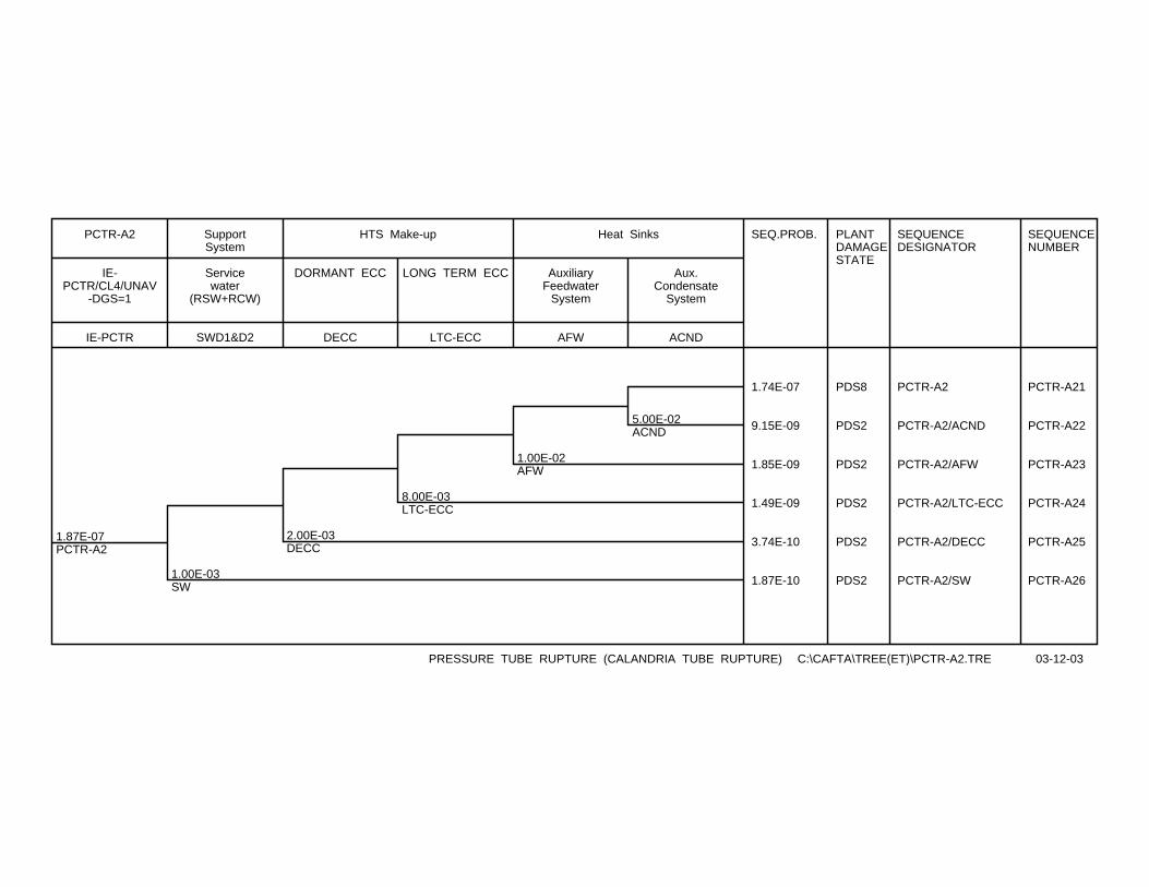
1.87E-07PCTR-A2
1.00E-03SW
2.00E-03DECC
8.00E-03LTC-ECC
1.00E-02AFW
5.00E-02ACND
SEQ.PROB. PLANTDAMAGESTATE
SEQUENCEDESIGNATOR
SEQUENCENUMBER
1.74E-07 PDS8 PCTR-A2 PCTR-A21
9.15E-09 PDS2 PCTR-A2/ACND PCTR-A22
1.85E-09 PDS2 PCTR-A2/AFW PCTR-A23
1.49E-09 PDS2 PCTR-A2/LTC-ECC PCTR-A24
3.74E-10 PDS2 PCTR-A2/DECC PCTR-A25
1.87E-10 PDS2 PCTR-A2/SW PCTR-A26
IE-PCTR
IE-PCTR/CL4/UNAV
-DGS=1
PCTR-A2
SWD1&D2
Servicewater
(RSW+RCW)
SupportSystem
DECC
DORMANT ECC
LTC-ECC
LONG TERM ECC
HTS Make-up
AFW
AuxiliaryFeedwater
System
ACND
Aux.Condensate
System
Heat Sinks
PRESSURE TUBE RUPTURE (CALANDRIA TUBE RUPTURE) C:\CAFTA\TREE(ET)\PCTR-A2.TRE 03-12-03
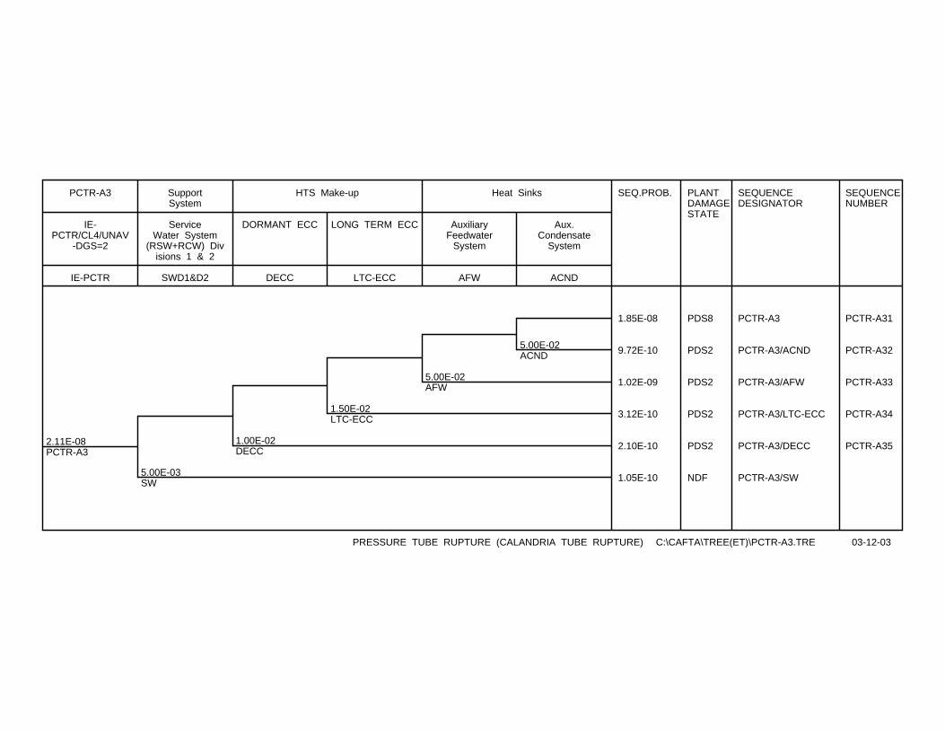
2.11E-08PCTR-A3
5.00E-03SW
1.00E-02DECC
1.50E-02LTC-ECC
5.00E-02AFW
5.00E-02ACND
SEQ.PROB. PLANTDAMAGESTATE
SEQUENCEDESIGNATOR
SEQUENCENUMBER
1.85E-08 PDS8 PCTR-A3 PCTR-A31
9.72E-10 PDS2 PCTR-A3/ACND PCTR-A32
1.02E-09 PDS2 PCTR-A3/AFW PCTR-A33
3.12E-10 PDS2 PCTR-A3/LTC-ECC PCTR-A34
2.10E-10 PDS2 PCTR-A3/DECC PCTR-A35
1.05E-10 NDF PCTR-A3/SW
IE-PCTR
IE-PCTR/CL4/UNAV
-DGS=2
PCTR-A3
SWD1&D2
ServiceWater System
(RSW+RCW) Divisions 1 & 2
SupportSystem
DECC
DORMANT ECC
LTC-ECC
LONG TERM ECC
HTS Make-up
AFW
AuxiliaryFeedwater
System
ACND
Aux.Condensate
System
Heat Sinks
PRESSURE TUBE RUPTURE (CALANDRIA TUBE RUPTURE) C:\CAFTA\TREE(ET)\PCTR-A3.TRE 03-12-03

1.81E-09PCTR-A4
1.00E-02SW
2.00E-02DECC
5.00E-02LTC-ECC
.10AFW
5.00E-02ACND
SEQ.PROB. PLANTDAMAGESTATE
SEQUENCEDESIGNATOR
SEQUENCENUMBER
1.43E-09 PDS8 PCTR-A4 PCTR-A41
7.51E-11 PDS2 PCTR-A4/ACND PCTR-A42
1.67E-10 PDS2 PCTR-A4/AFW PCTR-A43
8.78E-11 PDS2 PCTR-A4/LTC-ECC PCTR-A44
3.58E-11 PDS2 PCTR-A4/DECC PCTR-A45
1.81E-11 NDF PCTR-A4/SW
IE-PCTR
IE-PCTR/CL4/3
DG UN
PCTR-A4
SWD1&D2
ServiceWater System
(RSW+RCW) Divisions 1 & 2
SupportSystem
DECC
DORMANT ECC
LTC-ECC
LONG TERM ECC
HTS Make-up
AFW
AuxiliaryFeedwater
System
ACND
Aux.Condensate
System
Heat Sinks
PRESSURE TUBE RUPTURE (CALANDRIA TUBE RUPTURE) C:\CAFTA\TREE(ET)\PCTR-A4.TRE 06-11-03

CONTROLLED - Licensing 10810-03660-AR-001 Page C-1
Rev. 1
10810-03660-AR-001 2004/01/28
Appendix C
Event Tree for Feeder Break

2.00E-03IE-FBIO
1.00E-06RS
5.00E-02CL4
1.00E-05CC
1.00E-05SWD1&D2
7.00E-04DECC
5.00E-03LTC-ECC
5.00E-04FW
5.00E-03MHS
5.00E-03MHS
5.00E-03MHS
SEQ.FREQ. PLANTDAMAGESTATE
SEQUENCEDESIGNATOR
SEQUENCENUMBER
1.89E-03 PDS7 IE-FBIO FBIO1
9.40E-07 PDS4 IE-FBIO/FW FBIO2
4.72E-09 PDS2 IE-FBIO/FW/MHS FBIO3
9.45E-06 PDS4 IE-FBIO/LTC-ECC FBIO4
4.75E-08 PDS2 IE-FBIO/LTC-ECC/MHS FBIO5
1.32E-06 PDS4 IE-FBIO/DECC FBIO6
6.65E-09 PDS2 IE-FBIO/DECC/MHS FBIO7
1.90E-08 PDS2 IE-FBIO/SWD1&D2 FBIO8
1.90E-08 PDS1 IE-FBIO/CC FBIO9
1.00E-04 CONT’D IE-FBIO/CL4 FBIO-A
2.00E-09 PDS0 IE-FBIO/RS FBIO10
IE-FBIO
Feeder Break
InitiatingEvent
RS
SDS1&SDS2
ReactorShutdown
CL4
NoConsequentialloss of CL4
Supply
CC
CrashCooldown
SWD1&D2
SWD1&D2(RSW/RCW)System (CL4
available)
Support Systems
DECC
HTS Makeup
LTC-ECC
Long TermCooling
System (ECCfunction)
HTS Makeup
FW
FW Supply toSGs
MHS
ModeratorActs as Heat
Sink
Heat Sink
Fig.1 (Feeder Break) Page(1) C:\CAFTA\TREE(ET)\FBIO-01.TRE 28-01-04
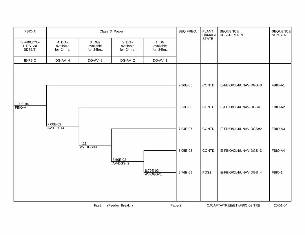
1.00E-04FBIO-A
7.00E-02AV-DGS<4
.11AV-DGS<3
8.60E-02AV-DGS<2
8.70E-02AV-DGS<1
SEQ.FREQ. PLANTDAMAGESTATE
SEQUENCEDESCRIPTION
SEQUENCENUMBER
9.30E-05 CONTD IE-FBIO/CL4/UNAV-DGS=0 FBIO-A1
6.23E-06 CONTD IE-FBIO/CL4/UNAV-DGS=1 FBIO-A2
7.04E-07 CONTD IE-FBIO/CL4/UNAV-DGS=2 FBIO-A3
6.05E-08 CONTD IE-FBIO/CL4/UNAV-DGS=3 FBIO-A4
5.76E-09 PDS1 IE-FBIO/CL4/UNAV-DGS=4 FBIO-1
IE-FBIO
IE-FBIO/CL4( RS viaSDS1/2)
FBIO-A
DG-AV=4
4 DGsavailable
for 24hrs.
DG-AV=3
3 DGsavailable
for 24hrs.
DG-AV=2
2 DGsavailable
for 24hrs.
DG-AV=1
1 DGavailable
for 24hrs.
Class 3 Power
Fig.2 (Feeder Break ) Page(2) C:\CAFTA\TREE(ET)\FBIO-02.TRE 20-01-04
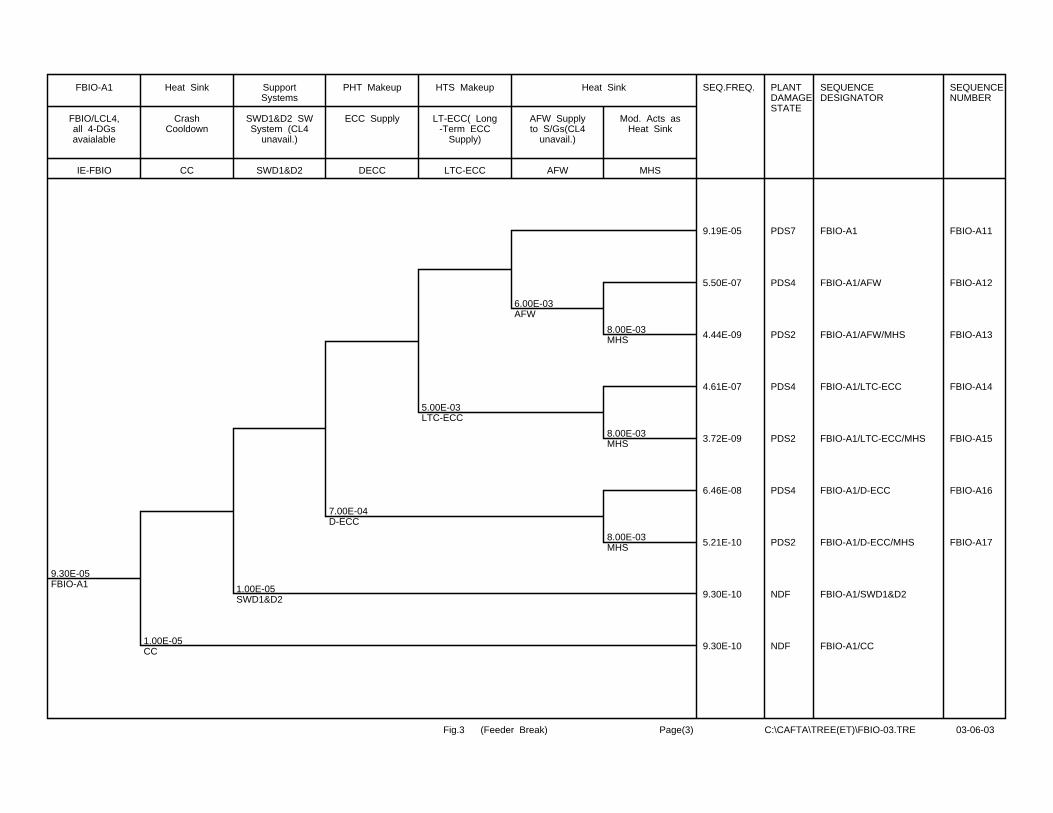
9.30E-05FBIO-A1
1.00E-05CC
1.00E-05SWD1&D2
7.00E-04D-ECC
5.00E-03LTC-ECC
6.00E-03AFW
8.00E-03MHS
8.00E-03MHS
8.00E-03MHS
SEQ.FREQ. PLANTDAMAGESTATE
SEQUENCEDESIGNATOR
SEQUENCENUMBER
9.19E-05 PDS7 FBIO-A1 FBIO-A11
5.50E-07 PDS4 FBIO-A1/AFW FBIO-A12
4.44E-09 PDS2 FBIO-A1/AFW/MHS FBIO-A13
4.61E-07 PDS4 FBIO-A1/LTC-ECC FBIO-A14
3.72E-09 PDS2 FBIO-A1/LTC-ECC/MHS FBIO-A15
6.46E-08 PDS4 FBIO-A1/D-ECC FBIO-A16
5.21E-10 PDS2 FBIO-A1/D-ECC/MHS FBIO-A17
9.30E-10 NDF FBIO-A1/SWD1&D2
9.30E-10 NDF FBIO-A1/CC
IE-FBIO
FBIO/LCL4,all 4-DGsavaialable
FBIO-A1
CC
CrashCooldown
Heat Sink
SWD1&D2
SWD1&D2 SWSystem (CL4
unavail.)
SupportSystems
DECC
ECC Supply
PHT Makeup
LTC-ECC
LT-ECC( Long-Term ECC
Supply)
HTS Makeup
AFW
AFW Supplyto S/Gs(CL4
unavail.)
MHS
Mod. Acts asHeat Sink
Heat Sink
Fig.3 (Feeder Break) Page(3) C:\CAFTA\TREE(ET)\FBIO-03.TRE 03-06-03
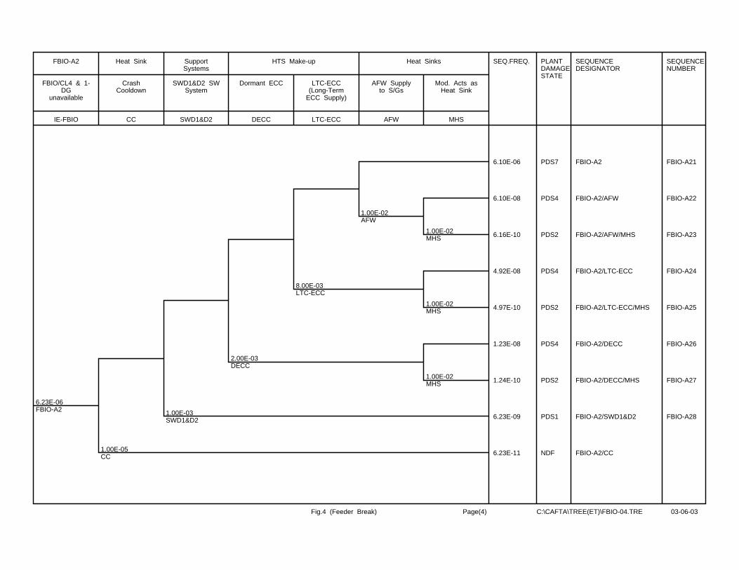
6.23E-06FBIO-A2
1.00E-05CC
1.00E-03SWD1&D2
2.00E-03DECC
8.00E-03LTC-ECC
1.00E-02AFW
1.00E-02MHS
1.00E-02MHS
1.00E-02MHS
SEQ.FREQ. PLANTDAMAGESTATE
SEQUENCEDESIGNATOR
SEQUENCENUMBER
6.10E-06 PDS7 FBIO-A2 FBIO-A21
6.10E-08 PDS4 FBIO-A2/AFW FBIO-A22
6.16E-10 PDS2 FBIO-A2/AFW/MHS FBIO-A23
4.92E-08 PDS4 FBIO-A2/LTC-ECC FBIO-A24
4.97E-10 PDS2 FBIO-A2/LTC-ECC/MHS FBIO-A25
1.23E-08 PDS4 FBIO-A2/DECC FBIO-A26
1.24E-10 PDS2 FBIO-A2/DECC/MHS FBIO-A27
6.23E-09 PDS1 FBIO-A2/SWD1&D2 FBIO-A28
6.23E-11 NDF FBIO-A2/CC
IE-FBIO
FBIO/CL4 & 1-DG
unavailable
FBIO-A2
CC
CrashCooldown
Heat Sink
SWD1&D2
SWD1&D2 SWSystem
SupportSystems
DECC
Dormant ECC
LTC-ECC
LTC-ECC(Long-Term
ECC Supply)
HTS Make-up
AFW
AFW Supplyto S/Gs
MHS
Mod. Acts asHeat Sink
Heat Sinks
Fig.4 (Feeder Break) Page(4) C:\CAFTA\TREE(ET)\FBIO-04.TRE 03-06-03

7.04E-07FBIO-A3
1.00E-05CC
5.00E-03SWD1&D2
1.00E-02DECC
1.50E-02LTC-ECC
5.00E-02AFW
5.00E-02MHS
5.00E-02MHS
5.00E-02MHS
SEQ.PROB. PLANTDAMAGESTATE
SEQUENCEDESIGNATOR
SEQUENCENUMBER
6.49E-07 PDS7 FBIO-A3 FBIO-A31
3.24E-08 PDS4 FBIO-A3/AFW FBIO-A32
1.71E-09 PDS2 FBIO-A3/AFW/MHS FBIO-A33
9.88E-09 PDS4 FBIO-A3/LTC-ECC FBIO-A34
5.20E-10 PDS2 FBIO-A3/LTC-ECC/MHS FBIO-A35
6.65E-09 PDS4 FBIO-A3/DECC FBIO-A36
3.50E-10 PDS2 FBIO-A3/DECC/MHS FBIO-A37
3.52E-09 PDS2 FBIO-A3/SWD1&D2 FBIO-A38
7.04E-12 NDF FBIO-A3/CC
IE-FBIO
FBIO/LCL4, 2-DGs
unavailable
FBIO-A3
CC
CrashCooldown
Heat Sink
SWD1&D2
SWD1&D2 SWSystem
SupportSystems
DECC
Dormant ECCSupply
LTC-ECC
Long-TermECC Supply
HTS Make-up
AFW
AFW Supplyto S/Gs
MHS
Mod. Acts AsHeat Sink
Heat Sinks
Fig.5 (Feeder Break) Page(5) C:\CAFTA\TREE(ET)\FBIO-05.TRE 03-06-03
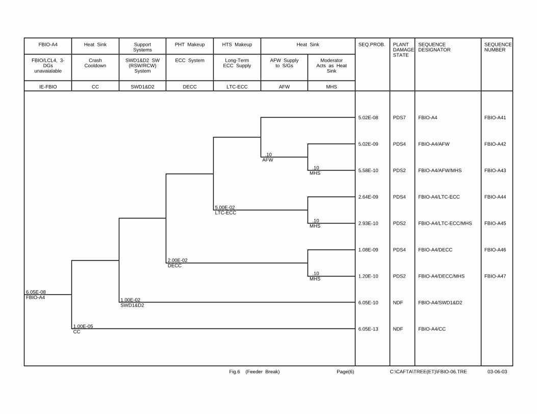
6.05E-08FBIO-A4
1.00E-05CC
1.00E-02SWD1&D2
2.00E-02DECC
5.00E-02LTC-ECC
.10AFW
.10MHS
.10MHS
.10MHS
SEQ.PROB. PLANTDAMAGESTATE
SEQUENCEDESIGNATOR
SEQUENCENUMBER
5.02E-08 PDS7 FBIO-A4 FBIO-A41
5.02E-09 PDS4 FBIO-A4/AFW FBIO-A42
5.58E-10 PDS2 FBIO-A4/AFW/MHS FBIO-A43
2.64E-09 PDS4 FBIO-A4/LTC-ECC FBIO-A44
2.93E-10 PDS2 FBIO-A4/LTC-ECC/MHS FBIO-A45
1.08E-09 PDS4 FBIO-A4/DECC FBIO-A46
1.20E-10 PDS2 FBIO-A4/DECC/MHS FBIO-A47
6.05E-10 NDF FBIO-A4/SWD1&D2
6.05E-13 NDF FBIO-A4/CC
IE-FBIO
FBIO/LCL4, 3-DGs
unavaialable
FBIO-A4
CC
CrashCooldown
Heat Sink
SWD1&D2
SWD1&D2 SW(RSW/RCW)
System
SupportSystems
DECC
ECC System
PHT Makeup
LTC-ECC
Long-TermECC Supply
HTS Makeup
AFW
AFW Supplyto S/Gs
MHS
ModeratorActs as Heat
Sink
Heat Sink
Fig.6 (Feeder Break) Page(6) C:\CAFTA\TREE(ET)\FBIO-06.TRE 03-06-03
CONTROLLED - Licensing 10810-03660-AR-001 Page D-1
Rev. 1
10810-03660-AR-001 2004/01/28
Appendix D
Event Tree for Feeder Stagnation Break
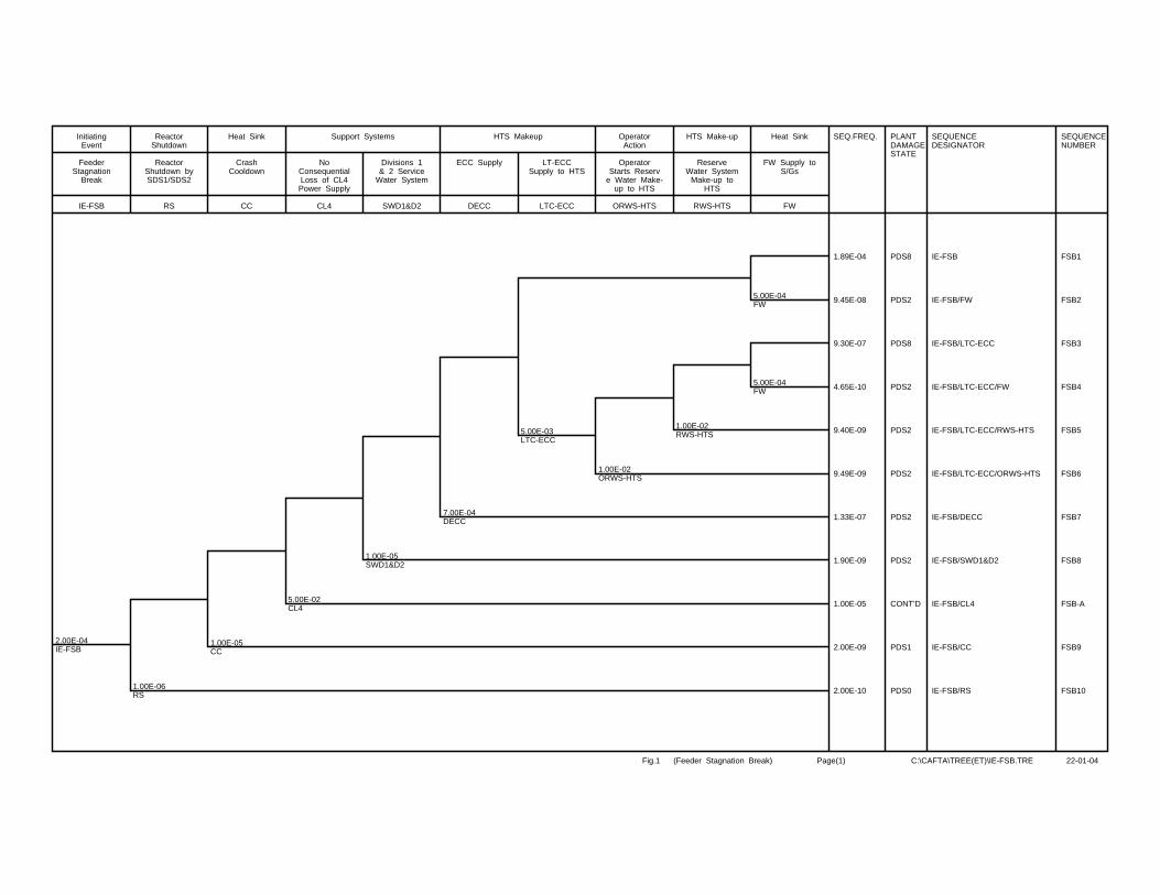
2.00E-04IE-FSB
1.00E-06RS
1.00E-05CC
5.00E-02CL4
1.00E-05SWD1&D2
7.00E-04DECC
5.00E-03LTC-ECC
1.00E-02ORWS-HTS
1.00E-02RWS-HTS
5.00E-04FW
5.00E-04FW
SEQ.FREQ. PLANTDAMAGESTATE
SEQUENCEDESIGNATOR
SEQUENCENUMBER
1.89E-04 PDS8 IE-FSB FSB1
9.45E-08 PDS2 IE-FSB/FW FSB2
9.30E-07 PDS8 IE-FSB/LTC-ECC FSB3
4.65E-10 PDS2 IE-FSB/LTC-ECC/FW FSB4
9.40E-09 PDS2 IE-FSB/LTC-ECC/RWS-HTS FSB5
9.49E-09 PDS2 IE-FSB/LTC-ECC/ORWS-HTS FSB6
1.33E-07 PDS2 IE-FSB/DECC FSB7
1.90E-09 PDS2 IE-FSB/SWD1&D2 FSB8
1.00E-05 CONT’D IE-FSB/CL4 FSB-A
2.00E-09 PDS1 IE-FSB/CC FSB9
2.00E-10 PDS0 IE-FSB/RS FSB10
IE-FSB
FeederStagnation
Break
InitiatingEvent
RS
ReactorShutdown bySDS1/SDS2
ReactorShutdown
CC
CrashCooldown
Heat Sink
CL4
NoConsequentialLoss of CL4Power Supply
SWD1&D2
Divisions 1& 2 Service
Water System
Support Systems
DECC
ECC Supply
LTC-ECC
LT-ECCSupply to HTS
HTS Makeup
ORWS-HTS
OperatorStarts Reserv
e Water Make-up to HTS
OperatorAction
RWS-HTS
ReserveWater System
Make-up toHTS
HTS Make-up
FW
FW Supply toS/Gs
Heat Sink
Fig.1 (Feeder Stagnation Break) Page(1) C:\CAFTA\TREE(ET)\IE-FSB.TRE 22-01-04
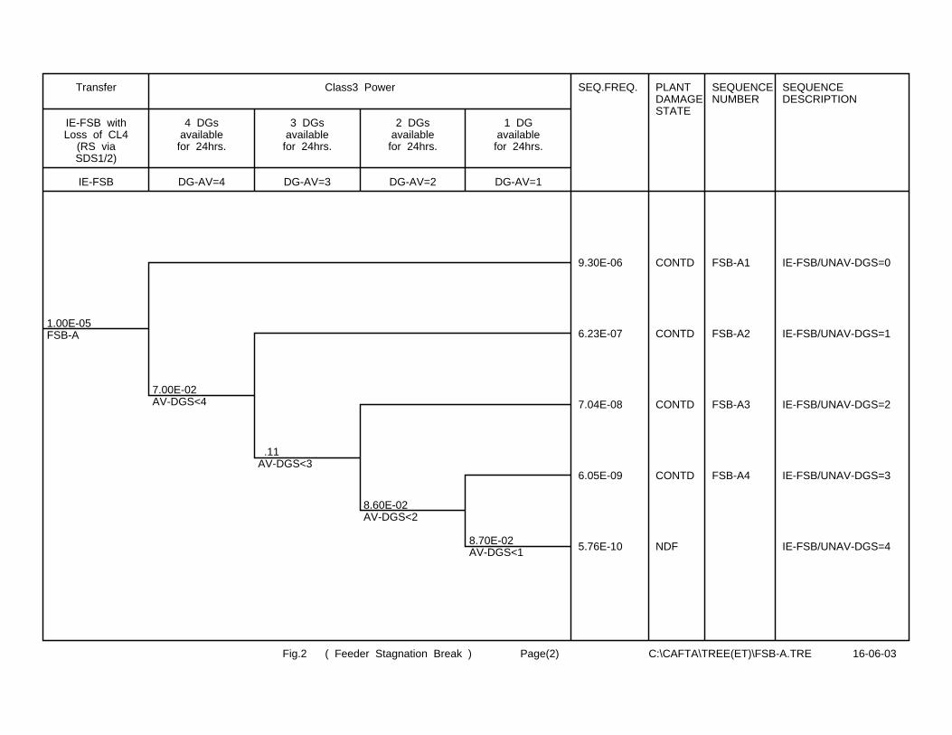
1.00E-05FSB-A
7.00E-02AV-DGS<4
.11AV-DGS<3
8.60E-02AV-DGS<2
8.70E-02AV-DGS<1
SEQ.FREQ. PLANTDAMAGESTATE
SEQUENCENUMBER
SEQUENCEDESCRIPTION
9.30E-06 CONTD FSB-A1 IE-FSB/UNAV-DGS=0
6.23E-07 CONTD FSB-A2 IE-FSB/UNAV-DGS=1
7.04E-08 CONTD FSB-A3 IE-FSB/UNAV-DGS=2
6.05E-09 CONTD FSB-A4 IE-FSB/UNAV-DGS=3
5.76E-10 NDF IE-FSB/UNAV-DGS=4
IE-FSB
IE-FSB withLoss of CL4
(RS viaSDS1/2)
Transfer
DG-AV=4
4 DGsavailable
for 24hrs.
DG-AV=3
3 DGsavailable
for 24hrs.
DG-AV=2
2 DGsavailablefor 24hrs.
DG-AV=1
1 DGavailablefor 24hrs.
Class3 Power
Fig.2 ( Feeder Stagnation Break ) Page(2) C:\CAFTA\TREE(ET)\FSB-A.TRE 16-06-03
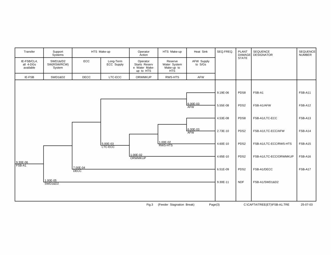
9.30E-06FSB-A1
1.00E-05SWD1&D2
7.00E-04DECC
5.00E-03LTC-ECC
1.00E-02ORWMKUP
1.00E-02RWS-HTS
6.00E-03AFW
6.00E-03AFW
SEQ.FREQ. PLANTDAMAGESTATE
SEQUENCEDESIGNATOR
SEQUENCENUMBER
9.19E-06 PDS8 FSB-A1 FSB-A11
5.55E-08 PDS2 FSB-A1/AFW FSB-A12
4.53E-08 PDS8 FSB-A1/LTC-ECC FSB-A13
2.73E-10 PDS2 FSB-A1/LTC-ECC/AFW FSB-A14
4.60E-10 PDS2 FSB-A1/LTC-ECC/RWS-HTS FSB-A15
4.65E-10 PDS2 FSB-A1/LTC-ECC/ORWMKUP FSB-A16
6.51E-09 PDS2 FSB-A1/DECC FSB-A17
9.30E-11 NDF FSB-A1/SWD1&D2
IE-FSB
IE-FSB/CL4,all 4-DGsavailable
Transfer
SWD1&D2
SWD1&/D2SW(RSW/RCW)
System
SupportSystems
DECC
ECC
LTC-ECC
Long-TermECC Supply
HTS Make-up
ORWMKUP
OperatorStarts Reserv
e Water Make-up to HTS
OperatorAction
RWS-HTS
ReserveWater System
Make-up toHTS
HTS Make-up
AFW
AFW Supplyto S/Gs
Heat Sink
Fig.3 (Feeder Stagnation Break) Page(3) C:\CAFTA\TREE(ET)\FSB-A1.TRE 25-07-03
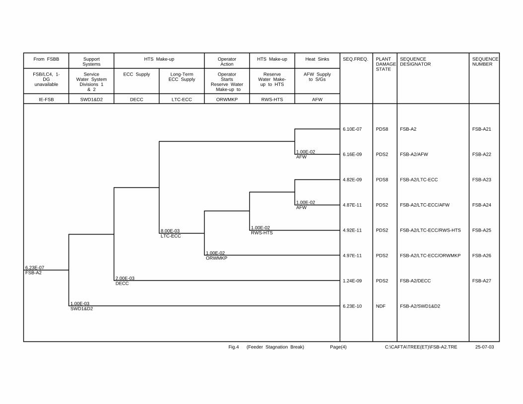
6.23E-07FSB-A2
1.00E-03SWD1&D2
2.00E-03DECC
8.00E-03LTC-ECC
1.00E-02ORWMKP
1.00E-02RWS-HTS
1.00E-02AFW
1.00E-02AFW
SEQ.FREQ. PLANTDAMAGESTATE
SEQUENCEDESIGNATOR
SEQUENCENUMBER
6.10E-07 PDS8 FSB-A2 FSB-A21
6.16E-09 PDS2 FSB-A2/AFW FSB-A22
4.82E-09 PDS8 FSB-A2/LTC-ECC FSB-A23
4.87E-11 PDS2 FSB-A2/LTC-ECC/AFW FSB-A24
4.92E-11 PDS2 FSB-A2/LTC-ECC/RWS-HTS FSB-A25
4.97E-11 PDS2 FSB-A2/LTC-ECC/ORWMKP FSB-A26
1.24E-09 PDS2 FSB-A2/DECC FSB-A27
6.23E-10 NDF FSB-A2/SWD1&D2
IE-FSB
FSB/LC4, 1-DG
unavailable
From FSBB
SWD1&D2
ServiceWater System
Divisions 1& 2
SupportSystems
DECC
ECC Supply
LTC-ECC
Long-TermECC Supply
HTS Make-up
ORWMKP
OperatorStarts
Reserve Water Make-up to
OperatorAction
RWS-HTS
ReserveWater Make-up to HTS
HTS Make-up
AFW
AFW Supplyto S/Gs
Heat Sinks
Fig.4 (Feeder Stagnation Break) Page(4) C:\CAFTA\TREE(ET)\FSB-A2.TRE 25-07-03

7.04E-08FSB-A3
5.00E-03SWD1&D2
1.00E-02DECC
1.50E-02LTC-ECC
1.00E-02ORWMKP
1.00E-02RWS-HTS
5.00E-02AFW
5.00E-02AFW
SEQ.PROB. PLANTDAMAGESTATE
SEQUENCEDESIGNATOR
SEQUENCENUMBER
6.49E-08 PDS8 FSB-A3 FSB-A31
3.42E-09 PDS2 FSB-A3/AFW FSB-A32
9.69E-10 PDS8 FSB-A3/LTC-ECC FSB-A33
5.10E-11 PDS2 FSB-A3/LTC-ECC/AFW FSB-A34
1.03E-11 PDS2 FSB-A3/LTC-ECC/RWS-HTS FSB-A35
1.04E-11 PDS2 FSB-A3/LTC-ECC/ORWMKP FSB-A36
7.00E-10 NDF FSB-A3/DECC
3.52E-10 NDF FSB-A3/SWD1&D2
IE-FSB
IE-FSB/CL4,2-DGs
Unavailable
Transfer
SWD1&D2
SWD1&D2SW(RSW/RCW)
System
SupportSystems
DECC
ECC Supply
LTC-ECC
Long-TermECC Supply
HTS Make-up
ORWMKP
OperatorStarts
ReserveWater Make-up
OperatorAction
RWS-HTS
ReserveWater Make-up to HTS
HTS Make-up
AFW
AFW Supplyto S/Gs
Heat Sinks
Fig.5 (Feeder Stagnation Break) Page(5) C:\CAFTA\TREE(ET)\FSB-A3.TRE 25-07-03
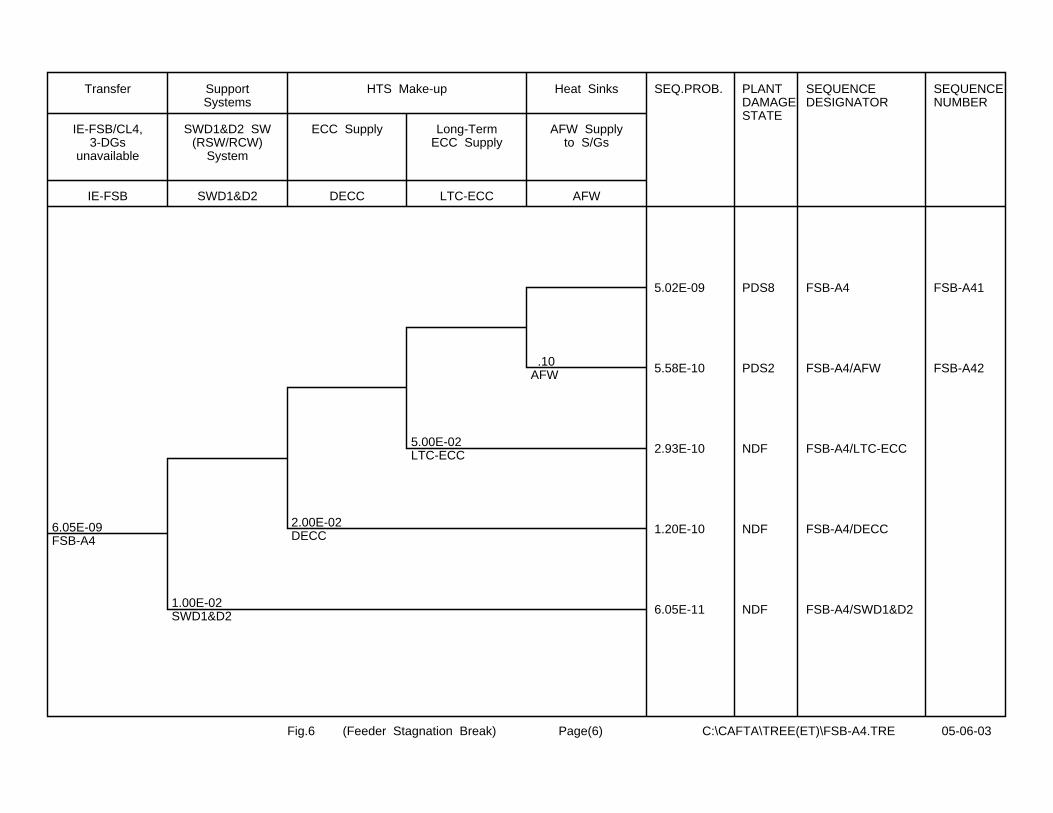
6.05E-09FSB-A4
1.00E-02SWD1&D2
2.00E-02DECC
5.00E-02LTC-ECC
.10AFW
SEQ.PROB. PLANTDAMAGESTATE
SEQUENCEDESIGNATOR
SEQUENCENUMBER
5.02E-09 PDS8 FSB-A4 FSB-A41
5.58E-10 PDS2 FSB-A4/AFW FSB-A42
2.93E-10 NDF FSB-A4/LTC-ECC
1.20E-10 NDF FSB-A4/DECC
6.05E-11 NDF FSB-A4/SWD1&D2
IE-FSB
IE-FSB/CL4,3-DGs
unavailable
Transfer
SWD1&D2
SWD1&D2 SW(RSW/RCW)
System
SupportSystems
DECC
ECC Supply
LTC-ECC
Long-TermECC Supply
HTS Make-up
AFW
AFW Supplyto S/Gs
Heat Sinks
Fig.6 (Feeder Stagnation Break) Page(6) C:\CAFTA\TREE(ET)\FSB-A4.TRE 05-06-03
CONTROLLED - Licensing 10810-03660-AR-001 Page E-1
Rev. 1
10810-03660-AR-001 2004/01/28
Appendix E
Event Tree for Total Loss of One Service Water Division
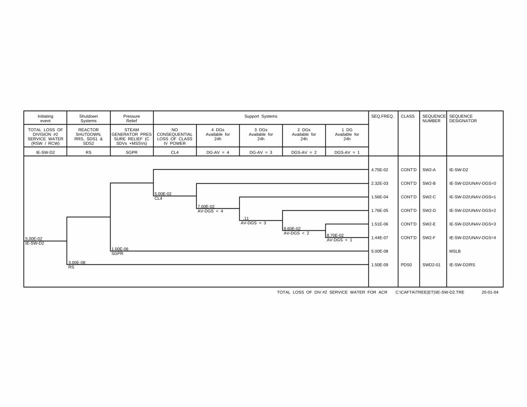
5.00E-02IE-SW-D2
3.00E-08RS
1.00E-06SGPR
5.00E-02CL4
7.00E-02AV-DGS < 4
.11AV-DGS < 3
8.60E-02AV-DGS < 2 8.70E-02
AV-DGS < 1
SEQ.FREQ. CLASS SEQUENCENUMBER
SEQUENCEDESIGNATOR
4.75E-02 CONT’D SW2-A IE-SW-D2
2.32E-03 CONT’D SW2-B IE-SW-D2/UNAV-DGS=0
1.56E-04 CONT’D SW2-C IE-SW-D2/UNAV-DGS=1
1.76E-05 CONT’D SW2-D IE-SW-D2/UNAV-DGS=2
1.51E-06 CONT’D SW2-E IE-SW-D2/UNAV-DGS=3
1.44E-07 CONT’D SW2-F IE-SW-D2/UNAV-DGS=4
5.00E-08 MSLB
1.50E-09 PDS0 SWD2-01 IE-SW-D2/RS
IE-SW-D2
TOTAL LOSS OFDIVISION #2
SERVICE WATER(RSW / RCW)
Initiatingevent
RS
REACTORSHUTDOWN,
RRS, SDS1 &SDS2
ShutdownSystems
SGPR
STEAMGENERATOR PRES
SURE RELIEF (CSDVs +MSSVs)
PressureRelief
CL4
NOCONSEQUENTIALLOSS OF CLASS
IV POWER
DG-AV = 4
4 DGsAvailable for
24h
DG-AV = 3
3 DGsAvailable for
24h
DGS-AV = 2
2 DGsAvailable for
24h
DGS-AV = 1
1 DGAvailable for
24h
Support Systems
TOTAL LOSS OF DIV.#2 SERVICE WATER FOR ACR C:\CAFTA\TREE(ET)\IE-SW-D2.TRE 20-01-04

4.75E-02SW2-A
8.00E-05CLPS
5.00E-03PTHT
5.00E-03PTHT
1.00E-02OPTHT
1.00E-05CC
1.00E-05CC
1.00E-05CC
5.00E-03D1SW
5.00E-03D1SW
5.00E-03D1SW
7.00E-04DECC
1.50E-02LTC-ECC
5.00E-03MHS
5.00E-03MHS
5.00E-03MHS
SEQ.FREQ. PLANTDAMAGESTATE
SEQUENCEDESIGNATOR
SEQUENCENUMBER
4.73E-02 CONT’D SW2-A SW2-A-1
2.35E-04 CONT’D SW2-A/PTHT SW2-A-2
2.35E-06 PDS4 SW2-A/PTHT/OPTHT SW2-A12
1.18E-08 PDS2 SW2-A/PTHT/OPTHT/MHS SW2-A13
1.19E-08 PDS2 SW2-A/PTHT/OPTHT/D1SW SW2-A14
2.37E-11 NDF SW2-A/PTHT/OPTHT/CC
3.76E-06 CONT’D SW2-A/CLPS SW2-A-3
2.58E-09 PDS4 SW2-A/CLPS/DECC SW2-A20
1.30E-11 PDS2 SW2-A/CLPS/DECC/MHS SW2-A21
3.95E-11 PDS1 SW2-A/CLPS/DECC/LTC-ECC SW2-A22
1.89E-08 PDS2 SW2-A/CLPS/D1SW SW2-A23
3.78E-11 NDF SW2-A/CLPS/CC
1.88E-08 PDS4 SW2-A/CLPS/PTHT SW2-A24
9.45E-11 PDS2 SW2-A/CLPS/PTHT/MHS SW2-A25
9.50E-11 PDS2 SW2-A/CLPS/PTHT/D1SW SW2-A26
1.90E-13 NDF SW2-A/CLPS/PTHT/CC
IE-SW2-A
Total Lossof Div. 2 SW
(RS & Cl4 Power Available)
InitiatingEvent Subset
CLPS
HTS PUMPSEAL
INTEGRITYMAINTAINED
PTHT
HTS PUMPSTRIP ON HIGH
UPPERBEARING TEMP.
HT System Integrity
OPTHT
OperatorTrips HTS
Pumps
SupportActions
CC
CRASHCOOLDOWN
D1SW
DIVISION #1SERVICE WATER
Support Systems
DECC
EmergencyCore Cooling
System
LTC-ECC
Long Term Cooling ECC System (includesreserve water
HTS Makeup
MHS
MODERATORSYSTEM ASHEAT SINK
UltimateHeat Sink
TOTAL LOSS OF DIVISION 2 SERVICE WATER FOR ACR C:\CAFTA\TREE(ET)\IE-SW2-A.TRE 22-01-04

4.73E-02SW2-A-1
5.00E-03D1SW
1.00E-03FW
3.00E-03AFW
5.00E-04CND
5.00E-04CND
1.00E-03OBPCC
1.00E-03OBPCC
5.00E-03BPCC
5.00E-03BPCC
1.00E-03OMSSV
1.00E-02OMSSV
1.00E-02LTC-SDC
1.00E-02LTC-SDC
1.00E-04ADW
1.00E-04ADW
1.00E-04ADW
1.00E-04EFW
1.00E-04EFW
1.00E-04EFW
1.00E-04EFW
1.00E-04EFW
1.00E-04EFW
1.00E-04EFW
SEQ.PROB. PLANTDAMAGESTATE
SEQUENCEDESIGNATOR
SEQUENCENUMBER
4.70E-02 S SW2-A-1
2.31E-05 S SW2-A-1/CND
2.34E-07 S SW2-A-1/CND/LTC-SDC
2.34E-11 PDS6 SW2-A-1/CND/LTC-SDC/EFW SW2-A1
1.16E-07 S SW2-A-1/CND/BPCC
1.17E-09 S SW2-A-1/CND/BPCC/LTC-SDC
1.17E-13 PDS6 SW2-A-1/CND/BPCC/LTC-SDC/EFW SW2-A2
1.17E-10 NDF SW2-A-1/CND/BPCC/OMSSV
2.35E-08 S SW2-A-1/CND/OBPCC
2.35E-12 PDS6 SW2-A-1/CND/OBPCC/EFW SW2-A3
2.35E-12 PDS6 SW2-A-1/CND/OBPCC/ADW SW2-A4
4.66E-05 S SW2-A-1/FW
4.66E-09 PDS6 SW2-A-1/FW/EFW SW2-A5
4.71E-07 S SW2-A-1/FW/OMSSV
4.71E-11 PDS6 SW2-A-1/FW/OMSSV/EFW SW2-A6
4.71E-11 PDS6 SW2-A-1/FW/OMSSV/ADW SW2-A7
2.36E-04 S SW2-A-1/D1SW
1.17E-07 S SW2-A-1/D1SW/CND
1.17E-11 PDS6 SW2-A-1/D1SW/CND/EFW SW2-A8
5.89E-10 NDF SW2-A-1/D1SW/CND/BPCC
1.18E-10 NDF SW2-A-1/D1SW/CND/OBPCC
7.09E-07 S SW2-A-1/D1SW/AFW
7.09E-11 PDS1 SW2-A-1/D1SW/AFW/EFW SW2-A8
7.09E-11 PDS1 SW2-A-1/D1SW/AFW/ADW SW2-A9
IE-SW-D2
LOSS OF DIV.#2 SW (HTS PUM
PS INTEGRITYPRESERVED)
InitiatingEvent Subset
D1SW
DIV. #1SERVICE WATER
SupportSystem
FW
FEEDWATERSYSTEM
AVAILABLE
CND
CONDENSATEWATER SYSTEM
(Main + Aux.)
Heat Sinks
OBPCC
OPERATORSTARTS BPCC
AND SDCSYSTEM
OperatorAction
BPCC
BOILERPRESSURECONTROL
COOLDOWN
Heat Sink
OMSSV / SGPR
OP. OPENS MSSVs /STEAM DIS
CHARGED PASSIVELY BY MSSVs
Op. Action /Passive H.S.
LTC-SDC
LONG TERM(SHUTDOWN)
COOLINGSYSTEM
ADW
AUTO-DEPRESSURIZAT
ION WATERSYSTEM
EFW
EMERGENCYFEEDWATERSUBSYSTEM
Heat Sinks
TOTAL LOSS OF DIVISION #2 SERVICE WATER C:\CAFTA\TREE(ET)\SW2-A-1.TRE 15-06-03
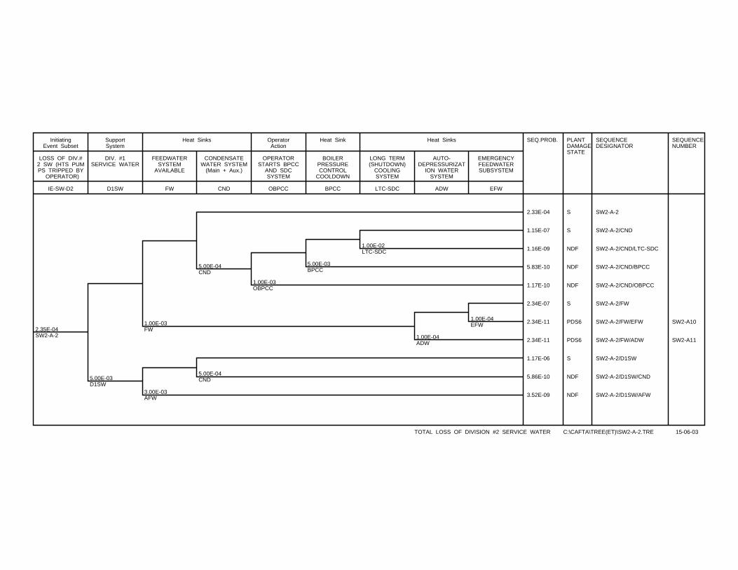
2.35E-04SW2-A-2
5.00E-03D1SW
1.00E-03FW
3.00E-03AFW
5.00E-04CND
5.00E-04CND
1.00E-03OBPCC
5.00E-03BPCC
1.00E-02LTC-SDC
1.00E-04ADW
1.00E-04EFW
SEQ.PROB. PLANTDAMAGESTATE
SEQUENCEDESIGNATOR
SEQUENCENUMBER
2.33E-04 S SW2-A-2
1.15E-07 S SW2-A-2/CND
1.16E-09 NDF SW2-A-2/CND/LTC-SDC
5.83E-10 NDF SW2-A-2/CND/BPCC
1.17E-10 NDF SW2-A-2/CND/OBPCC
2.34E-07 S SW2-A-2/FW
2.34E-11 PDS6 SW2-A-2/FW/EFW SW2-A10
2.34E-11 PDS6 SW2-A-2/FW/ADW SW2-A11
1.17E-06 S SW2-A-2/D1SW
5.86E-10 NDF SW2-A-2/D1SW/CND
3.52E-09 NDF SW2-A-2/D1SW/AFW
IE-SW-D2
LOSS OF DIV.#2 SW (HTS PUMPS TRIPPED BY
OPERATOR)
InitiatingEvent Subset
D1SW
DIV. #1SERVICE WATER
SupportSystem
FW
FEEDWATERSYSTEM
AVAILABLE
CND
CONDENSATEWATER SYSTEM
(Main + Aux.)
Heat Sinks
OBPCC
OPERATORSTARTS BPCC
AND SDCSYSTEM
OperatorAction
BPCC
BOILERPRESSURECONTROL
COOLDOWN
Heat Sink
LTC-SDC
LONG TERM(SHUTDOWN)
COOLINGSYSTEM
ADW
AUTO-DEPRESSURIZAT
ION WATERSYSTEM
EFW
EMERGENCYFEEDWATERSUBSYSTEM
Heat Sinks
TOTAL LOSS OF DIVISION #2 SERVICE WATER C:\CAFTA\TREE(ET)\SW2-A-2.TRE 15-06-03
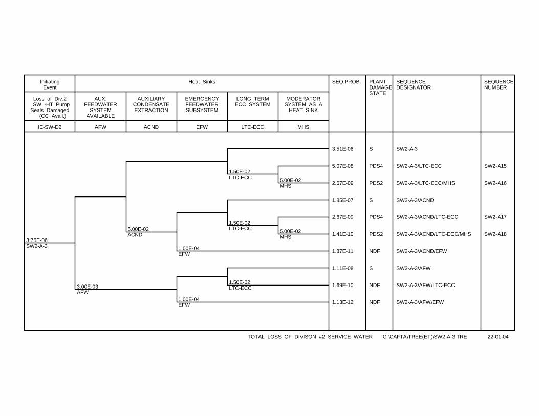
3.76E-06SW2-A-3
3.00E-03AFW
5.00E-02ACND
1.00E-04EFW
1.00E-04EFW
1.50E-02LTC-ECC
1.50E-02LTC-ECC
1.50E-02LTC-ECC
5.00E-02MHS
5.00E-02MHS
SEQ.PROB. PLANTDAMAGESTATE
SEQUENCEDESIGNATOR
SEQUENCENUMBER
3.51E-06 S SW2-A-3
5.07E-08 PDS4 SW2-A-3/LTC-ECC SW2-A15
2.67E-09 PDS2 SW2-A-3/LTC-ECC/MHS SW2-A16
1.85E-07 S SW2-A-3/ACND
2.67E-09 PDS4 SW2-A-3/ACND/LTC-ECC SW2-A17
1.41E-10 PDS2 SW2-A-3/ACND/LTC-ECC/MHS SW2-A18
1.87E-11 NDF SW2-A-3/ACND/EFW
1.11E-08 S SW2-A-3/AFW
1.69E-10 NDF SW2-A-3/AFW/LTC-ECC
1.13E-12 NDF SW2-A-3/AFW/EFW
IE-SW-D2
Loss of Div.2 SW -HT PumpSeals Damaged
(CC Avail.)
InitiatingEvent
AFW
AUX.FEEDWATER
SYSTEMAVAILABLE
ACND
AUXILIARYCONDENSATEEXTRACTION
EFW
EMERGENCYFEEDWATERSUBSYSTEM
LTC-ECC
LONG TERMECC SYSTEM
MHS
MODERATORSYSTEM AS A
HEAT SINK
Heat Sinks
TOTAL LOSS OF DIVISON #2 SERVICE WATER C:\CAFTA\TREE(ET)\SW2-A-3.TRE 22-01-04
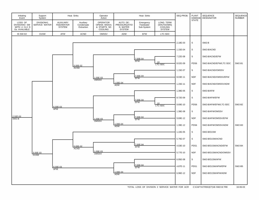
2.32E-03SW2-B
5.00E-03D1SW
6.00E-03AFW
6.00E-03AFW
5.00E-02ACND
5.00E-02ACND
1.00E-03OMSSV
1.00E-03OMSSV
1.00E-03OMSSV
1.00E-04ADW
1.00E-04ADW
1.00E-04ADW
7.00E-04EFW
7.00E-04EFW
7.00E-04EFW
7.00E-04EFW
7.00E-04EFW
7.00E-04EFW
.10LTC-SDC
.10LTC-SDC
SEQ.PROB. PLANTDAMAGESTATE
SEQUENCEDESIGNATOR
SEQUENCENUMBER
2.18E-03 S SW2-B
1.15E-04 S SW2-B/ACND
7.22E-08 S SW2-B/ACND/EFW
8.02E-09 PDS6 SW2-B/ACND/EFW/LTC-SDC SW2-B1
1.15E-07 S SW2-B/ACND/OMSSV
8.03E-11 NDF SW2-B/ACND/OMSSV/EFW
1.15E-11 NDF SW2-B/ACND/OMSSV/ADW
1.38E-05 S SW2-B/AFW
8.72E-09 S SW2-B/AFW/EFW
9.69E-10 PDS6 SW2-B/AFW/EFW/LTC-SDC SW2-B2
1.38E-08 S SW2-B/AFW/OMSSV
9.69E-12 NDF SW2-B/AFW/OMSSV/EFW
1.39E-12 PDS6 SW2-B/AFW/OMSSV/ADW SW2-B3
1.10E-05 S SW2-B/D1SW
5.76E-07 S SW2-B/D1SW/ACND
4.03E-10 PDS1 SW2-B/D1SW/ACND/EFW SW2-B4
5.77E-10 NDF SW2-B/D1SW/ACND/OMSSV
6.95E-08 S SW2-B/D1SW/AFW
4.87E-11 PDS1 SW2-B/D1SW/AFW/EFW SW2-B5
6.96E-12 NDF SW2-B/D1SW/AFW/ADW
IE-SW-D2
LOSS OFDIVISION#2 SW WITH 4 CL3 DGs AVAILABLE
InitiatingEvent
D1SW
DIVISION#1SERVICE WATER
SupportSystem
AFW
AUXILIARYFEEDWATER
SYSTEM
ACND
AuxiliaryCondensateExtraction
Heat Sinks
OMSSV
OPERATOROPENS MSSVs& STARTS SD
COOLING
OperatorAction
ADW
AUTO DE-PRESSURIZATIO
N WATERSYSTEM
EFW
EmergencyFeedwater
Sub-System
LTC-SDC
LONG TERM(SHUTDOWN)
COOLINGSYSTEM
Heat Sinks
TOTAL LOSS OF DIVISION 2 SERVICE WATER FOR ACR C:\CAFTA\TREE(ET)\IE-SW2-B.TRE 16-06-03

1.56E-04SW2-C
1.00E-02D1SW
1.00E-02AFW
1.00E-02AFW
5.00E-02ACND
5.00E-02ACND
1.00E-03OMSSV
1.00E-03OMSSV
1.00E-04ADW
1.00E-04ADW
1.00E-04ADW
7.00E-04EFW
7.00E-04EFW
7.00E-04EFW
7.00E-04EFW
1.00E-02OLTC-SDC
1.00E-02OLTC-SDC
.50LTC-SDC
.50LTC-SDC
SEQ.PROB. PLANTDAMAGESTATE
SEQUENCEDESIGNATOR
SEQUENCENUMBER
1.45E-04 S SW2-C
7.63E-06 S SW2-C/ACND
2.65E-09 S SW2-C/ACND/EFW
2.65E-09 PDS6 SW2-C/ACND/EFW/LTC-SDC SW2-C1
5.35E-11 PDS6 SW2-C/ACND/EFW/OLTC-SDC SW2-C2
7.64E-09 S SW2-C/ACND/OMSSV
7.64E-13 PDS6 SW2-C/ACND/OMSSV/ADW SW2-C3
1.54E-06 S SW2-C/AFW
5.35E-10 S SW2-C/AFW/EFW
5.35E-10 PDS6 SW2-C/AFW/EFW/LTC-SDC SW2-C4
1.08E-11 PDS6 SW2-C/AFW/EFW/OLTC-SDC SW2-C5
1.54E-10 PDS6 SW2-C/AFW/ADW SW2-C6
1.47E-06 S SW2-C/D1SW
7.71E-08 S SW2-C/D1SW/ACND
5.40E-11 PDS1 SW2-C/D1SW/ACND/EFW SW2-C7
7.72E-11 NDF SW2-C/D1SW/ACND/OMSSV
1.56E-08 S SW2-C/D1SW/AFW
1.09E-11 PDS1 SW2-C/D1SW/AFW/EFW SW2-C8
1.56E-12 PDS1 SW2-C/D1SW/AFW/ADW SW2-C9
IE-SW-D2
LOSS OFDIV#2 SW
WITH 3 DGsAVAILABLE
InitiatingEvent Subset
D1SW
DIVISION #1SERVICE WATER
Supprt System
AFW
AUXILIARYFEEDWATER
SYSTEM
ACND
AUXILIARYCONDENSATEEXTRACTION
Heat Sinks
OMSSV
OP. OPENSMSSVs AND
STARTS SDC /EFW
OperatorAction
ADW
AUTO-DEPRESSURIZAT
ION WATERSYSTEM
EFW
EmergencyFeedwater
System
Heat Sinks
OLTC-SDC
OPERATORINTIATES SDC
NORMAL MODE
OperatorAction
LTC-SDC
SHUTDOWNCOOLINGSYSTEM
Heat Sinks
TOTAL LOSS OF DIVISION #2 SERVICE WATER C:\CAFTA\TREE(ET)\IE-SW2-C.TRE 16-06-03
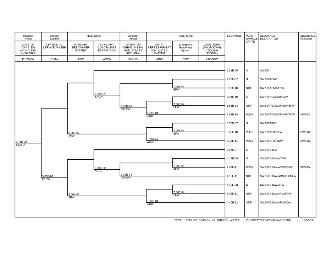
1.76E-05SW2-D
5.00E-02D1SW
5.00E-02AFW
5.00E-02AFW
5.00E-02ACND
5.00E-02ACND
1.00E-03OMSSV
1.00E-03OMSSV
1.00E-04ADW
1.00E-04ADW
1.00E-04ADW
7.00E-04EFW
7.00E-04EFW
7.00E-04EFW
7.00E-04EFW
7.00E-04EFW
SEQ.PROB. PLANTDAMAGESTATE
SEQUENCEDESIGNATOR
SEQUENCENUMBER
1.51E-05 S SW2-D
7.93E-07 S SW2-D/ACND
5.55E-10 NDF SW2-D/ACND/EFW
7.94E-10 S SW2-D/ACND/OMSSV
5.56E-13 NDF SW2-D/ACND/OMSSV/EFW
7.94E-14 PDS6 SW2-D/ACND/OMSSV/ADW SW2-D1
8.35E-07 S SW2-D/AFW
5.85E-10 PDS6 SW2-D/AFW/EFW SW2-D2
8.36E-11 PDS6 SW2-D/AFW/ADW SW2-D3
7.94E-07 S SW2-D/D1SW
4.17E-08 S SW2-D/D1SW/ACND
2.92E-11 PDS1 SW2-D/D1SW/ACND/EFW SW2-D4
4.18E-11 NDF SW2-D/D1SW/ACND/OMSSV
4.40E-08 S SW2-D/D1SW/AFW
3.08E-11 NDF SW2-D/D1SW/AFW/EFW
4.40E-12 NDF SW2-D/D1SW/AFW/ADW
IE-SW-D2
LOSS OFDIV#2 SW
WITH 2 DGsAVAILABLE
InitiatingEvent
D1SW
DIVISION #1SERVICE WATER
SupportSystem
AFW
AUXILIARYFEEDWATER
SYSTEM
ACND
AUXILIARYCONDENSATEEXTRACTION
Heat Sinks
OMSSV
OPERATOROPENS MSSVsAND STARTS
SDC /EFW
OperatorAction
ADW
AUTO-DEPRESSURIZAT
ION WATERSYSTEM
EFW
EmergencyFeedwater
System
LTC-SDC
LONG TERM(SHUTDOWN)
COOLINGSYSTEM
Heat Sinks
TOTAL LOSS OF DIVISION #2 SERVICE WATER C:\CAFTA\TREE(ET)\IE-SW2-D.TRE 16-06-03
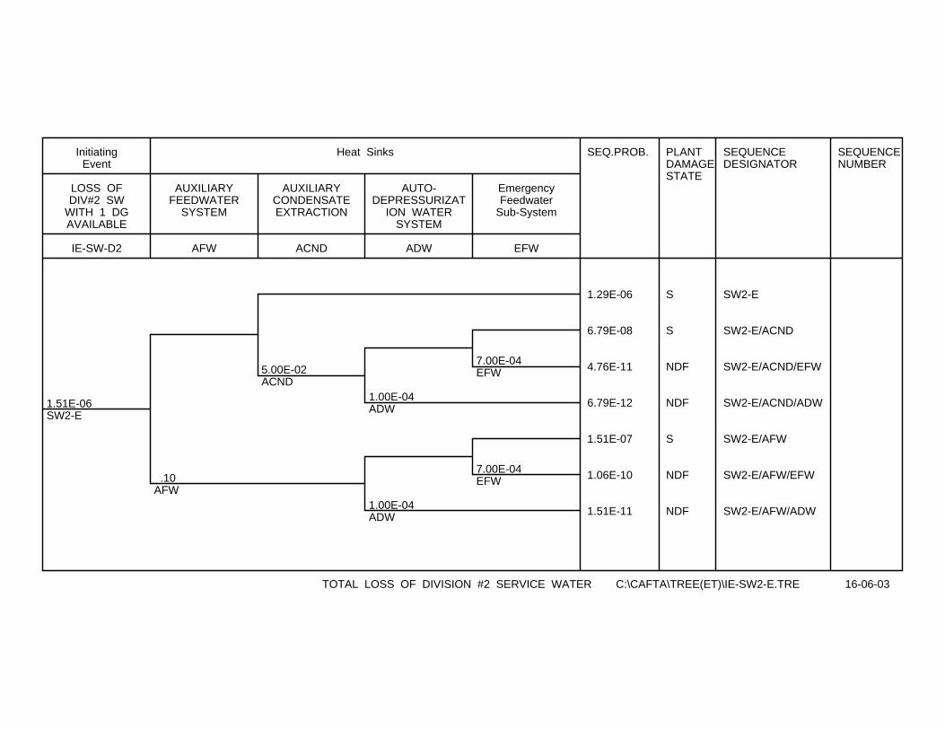
1.51E-06SW2-E
.10AFW
5.00E-02ACND
1.00E-04ADW
1.00E-04ADW
7.00E-04EFW
7.00E-04EFW
SEQ.PROB. PLANTDAMAGESTATE
SEQUENCEDESIGNATOR
SEQUENCENUMBER
1.29E-06 S SW2-E
6.79E-08 S SW2-E/ACND
4.76E-11 NDF SW2-E/ACND/EFW
6.79E-12 NDF SW2-E/ACND/ADW
1.51E-07 S SW2-E/AFW
1.06E-10 NDF SW2-E/AFW/EFW
1.51E-11 NDF SW2-E/AFW/ADW
IE-SW-D2
LOSS OFDIV#2 SW
WITH 1 DGAVAILABLE
InitiatingEvent
AFW
AUXILIARYFEEDWATER
SYSTEM
ACND
AUXILIARYCONDENSATEEXTRACTION
ADW
AUTO-DEPRESSURIZAT
ION WATERSYSTEM
EFW
EmergencyFeedwater
Sub-System
Heat Sinks
TOTAL LOSS OF DIVISION #2 SERVICE WATER C:\CAFTA\TREE(ET)\IE-SW2-E.TRE 16-06-03
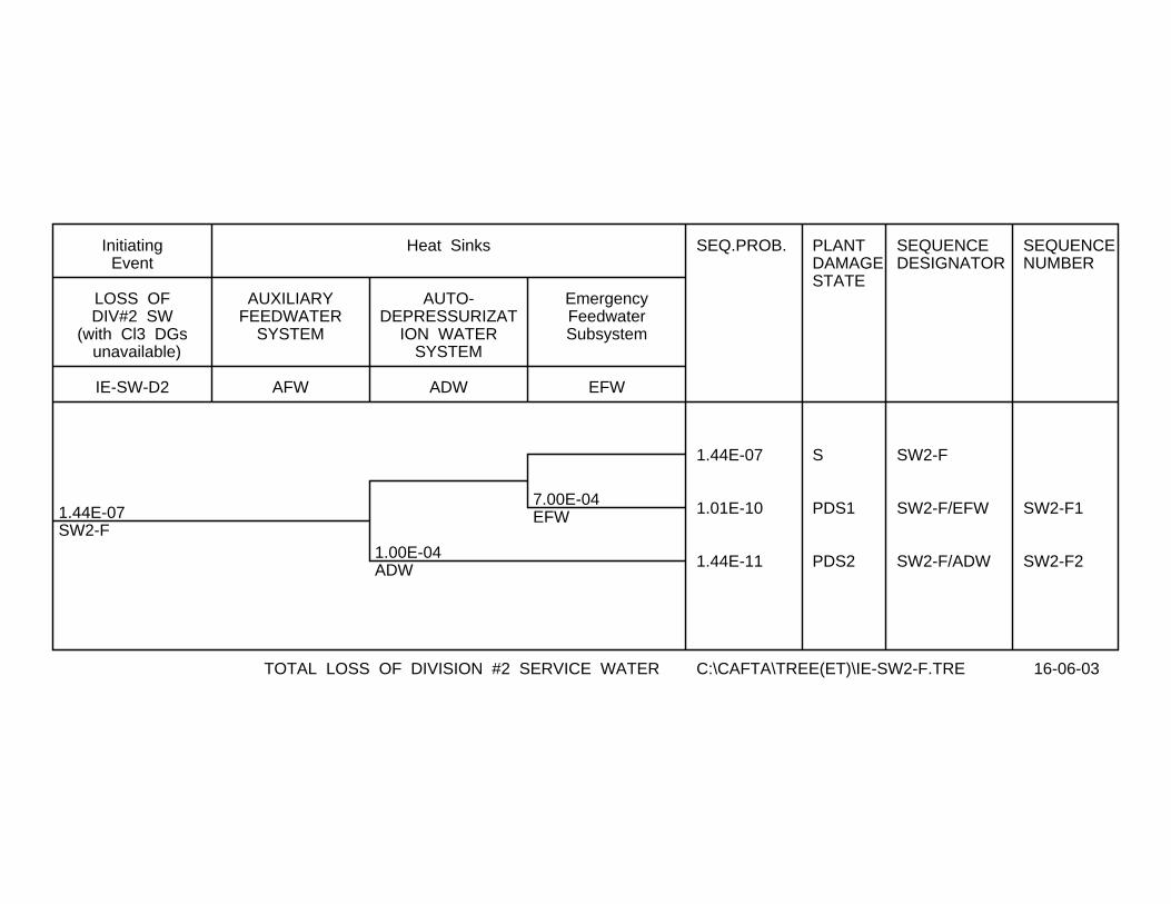
1.44E-07SW2-F
1.00E-04ADW
7.00E-04EFW
SEQ.PROB. PLANTDAMAGESTATE
SEQUENCEDESIGNATOR
SEQUENCENUMBER
1.44E-07 S SW2-F
1.01E-10 PDS1 SW2-F/EFW SW2-F1
1.44E-11 PDS2 SW2-F/ADW SW2-F2
IE-SW-D2
LOSS OFDIV#2 SW
(with Cl3 DGs unavailable)
InitiatingEvent
AFW
AUXILIARYFEEDWATER
SYSTEM
ADW
AUTO-DEPRESSURIZAT
ION WATERSYSTEM
EFW
EmergencyFeedwaterSubsystem
Heat Sinks
TOTAL LOSS OF DIVISION #2 SERVICE WATER C:\CAFTA\TREE(ET)\IE-SW2-F.TRE 16-06-03

CONTROLLED - Licensing 10810-03660-AR-001 Page F-1
Rev. 1
10810-03660-AR-001 2004/01/28
Appendix F
Event Tree for Loss of Class IV Power to One Unit
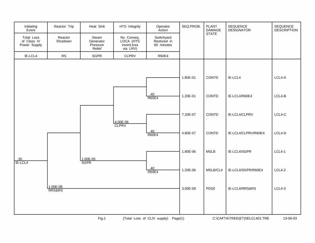
.30IE-LCL4
1.00E-08RRS&RS
1.00E-05SGPR
4.00E-06CLPRV
.40R60E4
.40R60E4
.40R60E4
SEQ.PROB. PLANTDAMAGESTATE
SEQUENCEDESIGNATOR
SEQUENCEDESCRIPTION
1.80E-01 CONTD IE-LCL4 LCL4-A
1.20E-01 CONTD IE-LCL4/R60E4 LCL4-B
7.20E-07 CONTD IE-LCL4/CLPRV LCL4-C
4.80E-07 CONTD IE-LCL4/CLPRV/R60E4 LCL4-D
1.80E-06 MSLB IE-LCL4/SGPR LCL4-1
1.20E-06 MSLB/CL4 IE-LCL4/SGPR/R60E4 LCL4-2
3.00E-09 PDS0 IE-LCL4/RRS&RS LCL4-3
IE-LCL4
Total Lossof Class IV
Power Supply
InitiatingEvent
RS
ReactorShutdown
Reactor Trip
SGPR
SteamGeneratorPressure
Relief
Heat Sink
CLPRV
No Conseq.LOCA (HTSinvent.lossvia LRV)
HTS Integrity
R60E4
SwitchyardRestored in60 minutes
OperatorAction
Fig.1 (Total Loss of CLIV supply) Page(1) C:\CAFTA\TREE(ET)\IELCL401.TRE 13-06-03

.18LCL4-A
1.00E-05SWD1&D2
3.50E-03MFW
3.00E-03AFW
3.00E-03AFW
5.00E-04CND
5.00E-04CND
1.00E-04ADW
1.00E-04ADW
1.00E-04ADW
1.00E-04ADW
1.00E-04EFW
1.00E-04EFW
1.00E-04EFW
1.00E-04EFW
1.00E-02OBPCC
5.00E-03BPCC
1.00E-02OLTC-SDC
1.00E-02LTC-SDC
SEQ.FREQ. PLANTDAMAGESTATE
SEQUENCEDESIGNATOR
SEQUENCEDESCRIPTION
1.79E-01 CONT LCL4-A LCL4-A1
6.28E-04 S LCL4-A/MFW
3.14E-07 S LCL4-A/MFW/CND
3.14E-11 NDF LCL4-A/MFW/CND/EFW
3.14E-11 NDF LCL4-A/MFW/CND/ADW
1.89E-06 S LCL4-A/MFW/AFW
1.85E-10 S LCL4-A/MFW/AFW/EFW
1.87E-12 PDS6 LCL4-A/MFW/AFW/EFW/LTC-SDC LCL4-A2
1.89E-12 NDF LCL4-A/MFW/AFW/EFW/OLTC-SDC
1.86E-10 S LCL4-A/MFW/AFW/ADW
9.36E-13 NDF LCL4-A/MFW/AFW/ADW/BPCC
1.89E-12 NDF LCL4-A/MFW/AFW/ADW/OBPCC
1.79E-06 S LCL4-A/SWD1&D2
8.97E-10 S LCL4-A/SWD1&D2/CND
8.97E-14 NDF LCL4-A/SWD1&D2/CND/EFW
8.97E-14 NDF LCL4-A/SWD1&D2/CND/ADW
5.40E-09 S LCL4-A/SWD1&D2/AFW
5.40E-13 NDF LCL4-A/SWD1&D2/AFW/EFW
5.40E-13 NDF LCL4-A/SWD1&D2/AFW/ADW
IE-LCL4
LCL4, CL4restored in60 minutes
From LCL4-A
SWD1&D2
SWD1&2 SW(CL4 power
unavail.)
SupportSystems
MFW
MFW Supplyto S/Gs
AFW
AFW Supplyto S/Gs
CND
CondensateSystem
ADW
Auto De-pressurizatio
n WaterSystem
EFW
EFW Supplyto S/Gs
Heat Sink
OBPCC
Operatorstatrts BPCC
system
OperatorAction
BPCC
BPCC system
Heat Sink
OLTC-SDC
OperatorStarts LTC-
SDC
OperatorAction
LTC-SDC
SDC System
Heat Sink
Fig.2 (Total Loss of CL4 supply) Page(2) C:\CAFTA\TREE(ET)\IELCL402.TRE 28-01-04
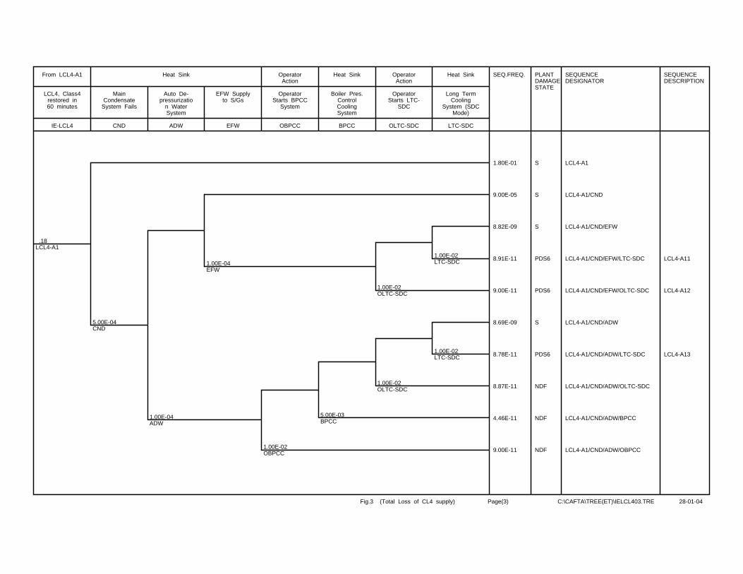
.18LCL4-A1
5.00E-04CND
1.00E-04ADW
1.00E-04EFW
1.00E-02OBPCC
5.00E-03BPCC
1.00E-02OLTC-SDC
1.00E-02OLTC-SDC
1.00E-02LTC-SDC
1.00E-02LTC-SDC
SEQ.FREQ. PLANTDAMAGESTATE
SEQUENCEDESIGNATOR
SEQUENCEDESCRIPTION
1.80E-01 S LCL4-A1
9.00E-05 S LCL4-A1/CND
8.82E-09 S LCL4-A1/CND/EFW
8.91E-11 PDS6 LCL4-A1/CND/EFW/LTC-SDC LCL4-A11
9.00E-11 PDS6 LCL4-A1/CND/EFW/OLTC-SDC LCL4-A12
8.69E-09 S LCL4-A1/CND/ADW
8.78E-11 PDS6 LCL4-A1/CND/ADW/LTC-SDC LCL4-A13
8.87E-11 NDF LCL4-A1/CND/ADW/OLTC-SDC
4.46E-11 NDF LCL4-A1/CND/ADW/BPCC
9.00E-11 NDF LCL4-A1/CND/ADW/OBPCC
IE-LCL4
LCL4, Class4restored in60 minutes
From LCL4-A1
CND
MainCondensate
System Fails
ADW
Auto De-pressurizatio
n WaterSystem
EFW
EFW Supplyto S/Gs
Heat Sink
OBPCC
OperatorStarts BPCC
System
OperatorAction
BPCC
Boiler Pres.ControlCoolingSystem
Heat Sink
OLTC-SDC
OperatorStarts LTC-
SDC
OperatorAction
LTC-SDC
Long TermCooling
System (SDCMode)
Heat Sink
Fig.3 (Total Loss of CL4 supply) Page(3) C:\CAFTA\TREE(ET)\IELCL403.TRE 28-01-04
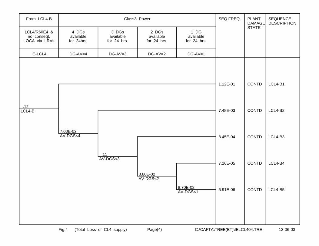
.12LCL4-B
7.00E-02AV-DGS<4
.11AV-DGS<3
8.60E-02AV-DGS<2
8.70E-02AV-DGS<1
SEQ.FREQ. PLANTDAMAGESTATE
SEQUENCEDESCRIPTION
1.12E-01 CONTD LCL4-B1
7.48E-03 CONTD LCL4-B2
8.45E-04 CONTD LCL4-B3
7.26E-05 CONTD LCL4-B4
6.91E-06 CONTD LCL4-B5
IE-LCL4
LCL4/R60E4 &no conseqt.
LOCA via LRVs
From LCL4-B
DG-AV=4
4 DGsavailable
for 24hrs.
DG-AV=3
3 DGsavailable
for 24 hrs.
DG-AV=2
2 DGsavailable
for 24 hrs.
DG-AV=1
1 DGavailable
for 24 hrs.
Class3 Power
Fig.4 (Total Loss of CL4 supply) Page(4) C:\CAFTA\TREE(ET)\IELCL404.TRE 13-06-03
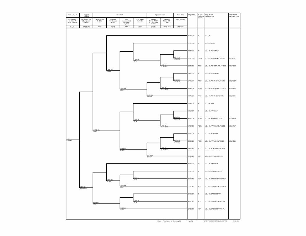
.11LCL4-B1
1.00E-05SWD1&D2
6.00E-03AFW
6.00E-03AFW
5.00E-02ACND
5.00E-02ACND
1.00E-04ADW
1.00E-04ADW
1.00E-04ADW
1.00E-04ADW
7.00E-04EFW
7.00E-04EFW
7.00E-04EFW
7.00E-04EFW
1.00E-02OMSSV
1.00E-02OMSSV
1.00E-02OLTC-SDC
1.00E-02OLTC-SDC
1.00E-02OLTC-SDC
1.00E-02OLTC-SDC
1.00E-02LTC-SDC
1.00E-02LTC-SDC
1.00E-02LTC-SDC
1.00E-02LTC-SDC
SEQ.FREQ. PLANTDAMAGESTATE
SEQUENCEDESIGNATOR
SEQUENCEDESCRIPTION
1.06E-01 S LCL4-B1
5.56E-03 S LCL4-B1/ACND
3.82E-06 S LCL4-B1/ACND/EFW
3.86E-08 PDS6 LCL4-B1/ACND/EFW/LTC-SDC LCL4-B11
3.90E-08 PDS6 LCL4-B1/ACND/EFW/OLTC-SDC LCL4-B12
5.40E-07 S LCL4-B1/ACND/ADW
5.46E-09 PDS6 LCL4-B1/ACND/ADW/LTC-SDC LCL4-B13
5.51E-09 PDS6 LCL4-B1/ACND/ADW/OLTC-SDC LCL4-B14
5.57E-09 PDS6 LCL4-B1/ACND/ADW/OMSSV LCL4-B15
6.71E-04 S LCL4-B1/AFW
4.61E-07 S LCL4-B1/AFW/EFW
4.66E-09 PDS6 LCL4-B1/AFW/EFW/LTC-SDC LCL4-B16
4.70E-09 PDS6 LCL4-B1/AFW/EFW/OLTC-SDC LCL4-B17
6.52E-08 S LCL4-B1/AFW/ADW
6.59E-10 PDS6 LCL4-B1/AFW/ADW/LTC-SDC LCL4-B18
6.65E-10 NDF LCL4-B1/AFW/ADW/OLTC-SDC
6.72E-10 NDF LCL4-B1/AFW/ADW/OMSSV
1.06E-06 S LCL4-B1/SWD1&D2
5.56E-08 S LCL4-B1/SWD1&D2/ACND
3.90E-11 NDF LCL4-B1/SWD1&D2/ACND/EFW
5.57E-12 NDF LCL4-B1/SWD1&D2/ACND/ADW
6.71E-09 S LCL4-B1/SWD1&D2/AFW
4.70E-12 NDF LCL4-B1/SWD1&D2/AFW/EFW
6.72E-13 NDF LCL4-B1/SWD1&D2/AFW/ADW
IE-LCL4
LCL4/R60E4 -at least 4-
DGs available
From LCL4-B1
SWD1&D2
SWD1&D2 SW(CL4 power
unavail.)
SupportSystems
AFW
AFW Supplyto SGs
ACND
AuxiliaryCondensate
Pump
ADW
auto-depressurizat
ion watersystem
EFW
EFW Supplyto S/Gs
Heat Sink
OMSSV
OperatorOpens MSSVsto De-pressur
ize SGs
OLTC-SDC
OperatorStarts LTC-
SDC
Operator Action
LTC-SDC
SDC System
Heat Sink
Fig.5 (Total Loss of CL4 supply) Page(5) C:\CAFTA\TREE(ET)\IELCL405.TRE 28-01-04
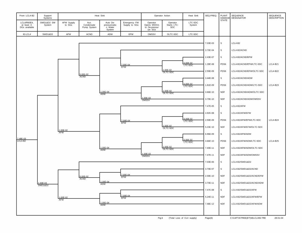
7.48E-03LCL4-B2
1.00E-03SWD1&D2
1.00E-02AFW
1.00E-02AFW
5.00E-02ACND
5.00E-02ACND
1.00E-04ADW
1.00E-04ADW
1.00E-04ADW
1.00E-04ADW
7.00E-04EFW
7.00E-04EFW
7.00E-04EFW
7.00E-04EFW
1.00E-02OMSSV
1.00E-02OMSSV
1.00E-02OLTC-SDC
1.00E-02OLTC-SDC
1.00E-02OLTC-SDC
1.00E-02OLTC-SDC
5.00E-02LTC-SDC
5.00E-02LTC-SDC
5.00E-02LTC-SDC
5.00E-02LTC-SDC
SEQ.FREQ. PLANTDAMAGESTATE
SEQUENCEDESIGNATOR
SEQUENCEDESCRIPTION
7.03E-03 S LCL4-B2
3.70E-04 S LCL4-B2/ACND
2.43E-07 S LCL4-B2/ACND/EFW
1.28E-08 PDS6 LCL4-B2/ACND/EFW/LTC-SDC LCL4-B21
2.59E-09 PDS6 LCL4-B2/ACND/EFW/OLTC-SDC LCL4-B22
3.44E-08 S LCL4-B2/ACND/ADW
1.81E-09 PDS6 LCL4-B2/ACND/ADW/LTC-SDC LCL4-B23
3.66E-10 NDF LCL4-B2/ACND/ADW/OLTC-SDC
3.70E-10 NDF LCL4-B2/ACND/ADW/OMSSV
7.47E-05 S LCL4-B2/AFW
4.92E-08 S LCL4-B2/AFW/EFW
2.59E-09 PDS6 LCL4-B2/AFW/EFW/LTC-SDC LCL4-B24
5.23E-10 NDF LCL4-B2/AFW/EFW/OLTC-SDC
6.96E-09 S LCL4-B2/AFW/ADW
3.66E-10 PDS6 LCL4-B2/AFW/ADW/LTC-SDC LCL4-B25
7.40E-11 NDF LCL4-B2/AFW/ADW/OLTC-SDC
7.47E-11 NDF LCL4-B2/AFW/ADW/OMSSV
7.03E-06 S LCL4-B2/SWD1&D2
3.70E-07 S LCL4-B2/SWD1&D2/ACND
2.59E-10 NDF LCL4-B2/SWD1&D2/ACND/EFW
3.70E-11 NDF LCL4-B2/SWD1&D2/ACND/ADW
7.47E-08 S LCL4-B2/SWD1&D2/AFW
5.24E-11 NDF LCL4-B2/SWD1&D2/AFW/EFW
7.48E-12 NDF LCL4-B2/SWD1&D2/AFW/ADW
IE-LCL4
LCL4/R60E4,at least 3-
DGs available
From LCL4-B2
SWD1&D2
SWD1&D2 SWSystem
SupportSystems
AFW
AFW Supplyto SGs
ACND
Aux.Condensate
Pump System
ADW
Auto De-pressurizatio
n WaterSystem
EFW
Emergency FWSupply to SGs
Heat Sink
OMSSV
OperatorOpens MSSVsto De-pressur
ize SGs
OLTC-SDC
OperatorStarts LTC-
SDC
Operator Action
LTC-SDC
LTC-SDCSystem
Heat Sink
Fig.6 (Total Loss of CL4 supply) Page(6) C:\CAFTA\TREE(ET)\IELCL406.TRE 28-01-04
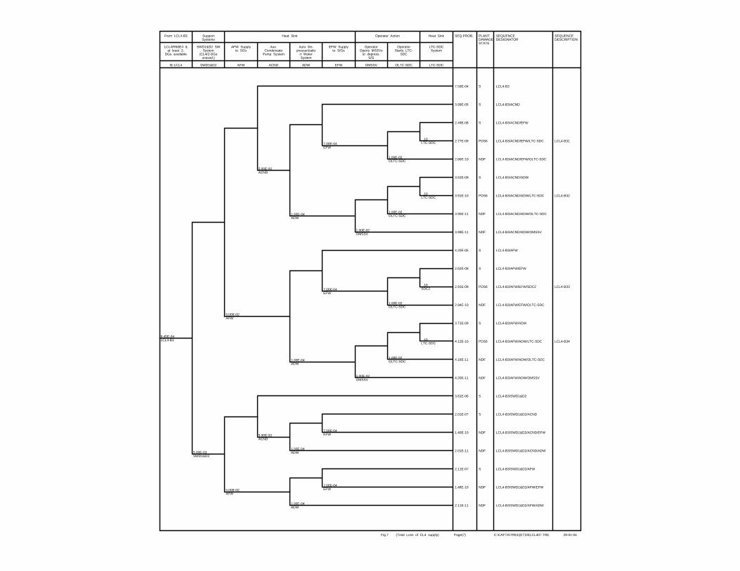
8.45E-04LCL4-B3
5.00E-03SWD1&D2
5.00E-02AFW
5.00E-02AFW
5.00E-02ACND
5.00E-02ACND
1.00E-04ADW
1.00E-04ADW
1.00E-04ADW
1.00E-04ADW
7.00E-04EFW
7.00E-04EFW
7.00E-04EFW
7.00E-04EFW
1.00E-02OMSSV
1.00E-02OMSSV
1.00E-02OLTC-SDC
1.00E-02OLTC-SDC
1.00E-02OLTC-SDC
1.00E-02OLTC-SDC
.10LTC-SDC
.10LTC-SDC
.10SDC2
.10LTC-SDC
SEQ.PROB. PLANTDAMAGESTATE
SEQUENCEDESIGNATOR
SEQUENCEDESCRIPTION
7.59E-04 S LCL4-B3
3.99E-05 S LCL4-B3/ACND
2.49E-08 S LCL4-B3/ACND/EFW
2.77E-09 PDS6 LCL4-B3/ACND/EFW/LTC-SDC LCL4-B31
2.80E-10 NDF LCL4-B3/ACND/EFW/OLTC-SDC
3.52E-09 S LCL4-B3/ACND/ADW
3.91E-10 PDS6 LCL4-B3/ACND/ADW/LTC-SDC LCL4-B32
3.95E-11 NDF LCL4-B3/ACND/ADW/OLTC-SDC
3.99E-11 NDF LCL4-B3/ACND/ADW/OMSSV
4.20E-05 S LCL4-B3/AFW
2.62E-08 S LCL4-B3/AFW/EFW
2.91E-09 PDS6 LCL4-B3/AFW/EFW/SDC2 LCL4-B33
2.94E-10 NDF LCL4-B3/AFW/EFW/OLTC-SDC
3.71E-09 S LCL4-B3/AFW/ADW
4.12E-10 PDS6 LCL4-B3/AFW/ADW/LTC-SDC LCL4-B34
4.16E-11 NDF LCL4-B3/AFW/ADW/OLTC-SDC
4.20E-11 NDF LCL4-B3/AFW/ADW/OMSSV
3.81E-06 S LCL4-B3/SWD1&D2
2.01E-07 S LCL4-B3/SWD1&D2/ACND
1.40E-10 NDF LCL4-B3/SWD1&D2/ACND/EFW
2.01E-11 NDF LCL4-B3/SWD1&D2/ACND/ADW
2.11E-07 S LCL4-B3/SWD1&D2/AFW
1.48E-10 NDF LCL4-B3/SWD1&D2/AFW/EFW
2.11E-11 NDF LCL4-B3/SWD1&D2/AFW/ADW
IE-LCL4
LCL4/R60E4 &at least 2-
DGs available
From LCL4-B3
SWD1&D2
SWD1&D2 SWSystem
(CL4/2-DGsunavail.)
SupportSystems
AFW
AFW Supplyto SGs
ACND
Aux.Condensate
Pump System
ADW
Auto De-pressurizatio
n WaterSystem
EFW
EFW Supplyto S/Gs
Heat Sink
OMSSV
OperatorOpens MSSVs
to depress.S/G
OLTC-SDC
OperatorStarts LTC-
SDC
Operator Action
LTC-SDC
LTC-SDCSystem
Heat Sink
Fig.7 (Total Loss of CL4 supply) Page(7) C:\CAFTA\TREE(ET)\IELCL407.TRE 28-01-04
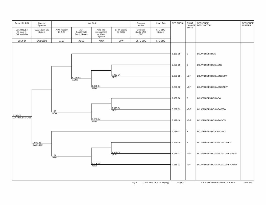
7.26E-05LCL4/R60E4/3-DGS
1.00E-02SWD1&D2
.10AFW
.10AFW
5.00E-02ACND
1.00E-04ADW
1.00E-04ADW
1.00E-04ADW
7.00E-04EFW
7.00E-04EFW
7.00E-04EFW
SEQ.PROB. PLANTDAMAGESTATE
SEQUENCEDESIGNATOR
SEQUENCENUMBER
6.15E-05 S LCL4/R60E4/3-DGS
3.23E-06 S LCL4/R60E4/3-DGS/ACND
2.26E-09 NDF LCL4/R60E4/3-DGS/ACND/EFW
3.23E-10 NDF LCL4/R60E4/3-DGS/ACND/ADW
7.18E-06 S LCL4/R60E4/3-DGS/AFW
5.03E-09 NDF LCL4/R60E4/3-DGS/AFW/EFW
7.19E-10 NDF LCL4/R60E4/3-DGS/AFW/ADW
6.53E-07 S LCL4/R60E4/3-DGS/SWD1&D2
7.25E-08 S LCL4/R60E4/3-DGS/SWD1&D2/AFW
5.08E-11 NDF LCL4/R60E4/3-DGS/SWD1&D2/AFW/EFW
7.26E-12 NDF LCL4/R60E4/3-DGS/SWD1&D2/AFW/ADW
LCL4-B4
LCL4/R60E4,at least 1-
DG available
From LCL4-B4
SWD1&D2
SWD1&D2 SWSystem
SupportSystems
AFW
AFW Supplyto SGs
ACND
Aux.Condensate
Pump System
ADW
Auto De-pressurizatio
n WaterSystem
EFW
EFW Supplyto S/Gs
Heat Sink
OLTC-SDC
OperatorStarts LTC-
SDC
OperatorAction
LTC-SDC
LTC-SDCSystem
Heat Sink
Fig.8 (Total Loss of CL4 supply) Page(8) C:\CAFTA\TREE(ET)\IELCL408.TRE 28-01-04
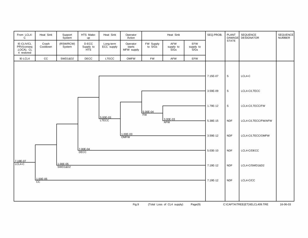
7.19E-07LCL4-C
1.00E-05CC
1.00E-05SWD1&D2
7.00E-04DECC
5.00E-03LTECC
1.00E-03OMFW
5.00E-04FW
3.00E-03AFW
SEQ.PROB. PLANTDAMAGESTATE
SEQUENCEDESIGNATOR
SEQUENCENUMBER
7.15E-07 S LCL4-C
3.59E-09 S LCL4-C/LTECC
1.79E-12 S LCL4-C/LTECC/FW
5.38E-15 NDF LCL4-C/LTECC/FW/AFW
3.59E-12 NDF LCL4-C/LTECC/OMFW
5.03E-10 NDF LCL4-C/DECC
7.19E-12 NDF LCL4-C/SWD1&D2
7.19E-12 NDF LCL4-C/CC
IE-LCL4
IE-CLIV/CLPRV(conseq.LOCA), CL4 restored
From LCL4-C
CC
CrashCooldown
Heat Sink
SWD1&D2
(RSW/RCW)System
SupportSystem
DECC
D-ECCSupply to
HTS
HTS Make-up
LTECC
Long-termECC supply
Heat Sink
OMFW
Operatorstarts
MFW supply
OperatorAction
FW
FW Supplyto S/Gs
AFW
AFWsupply to
S/Gs
EFW
EFWsupply to
S/Gs
Heat Sink
Fig.9 (Total Loss of CL4 supply) Page(9) C:\CAFTA\TREE(ET)\IELCL409.TRE 16-06-03
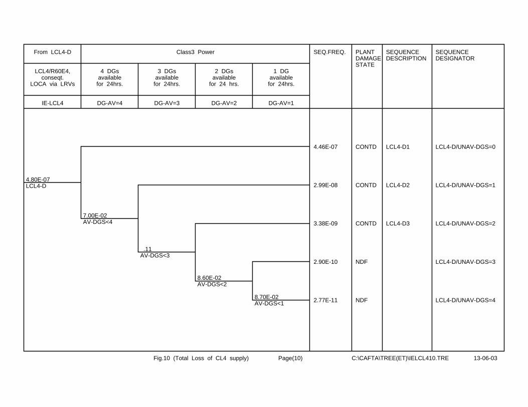
4.80E-07LCL4-D
7.00E-02AV-DGS<4
.11AV-DGS<3
8.60E-02AV-DGS<2
8.70E-02AV-DGS<1
SEQ.FREQ. PLANTDAMAGESTATE
SEQUENCEDESCRIPTION
SEQUENCEDESIGNATOR
4.46E-07 CONTD LCL4-D1 LCL4-D/UNAV-DGS=0
2.99E-08 CONTD LCL4-D2 LCL4-D/UNAV-DGS=1
3.38E-09 CONTD LCL4-D3 LCL4-D/UNAV-DGS=2
2.90E-10 NDF LCL4-D/UNAV-DGS=3
2.77E-11 NDF LCL4-D/UNAV-DGS=4
IE-LCL4
LCL4/R60E4,conseqt.
LOCA via LRVs
From LCL4-D
DG-AV=4
4 DGsavailable
for 24hrs.
DG-AV=3
3 DGsavailable
for 24hrs.
DG-AV=2
2 DGsavailable
for 24 hrs.
DG-AV=1
1 DGavailable
for 24hrs.
Class3 Power
Fig.10 (Total Loss of CL4 supply) Page(10) C:\CAFTA\TREE(ET)\IELCL410.TRE 13-06-03
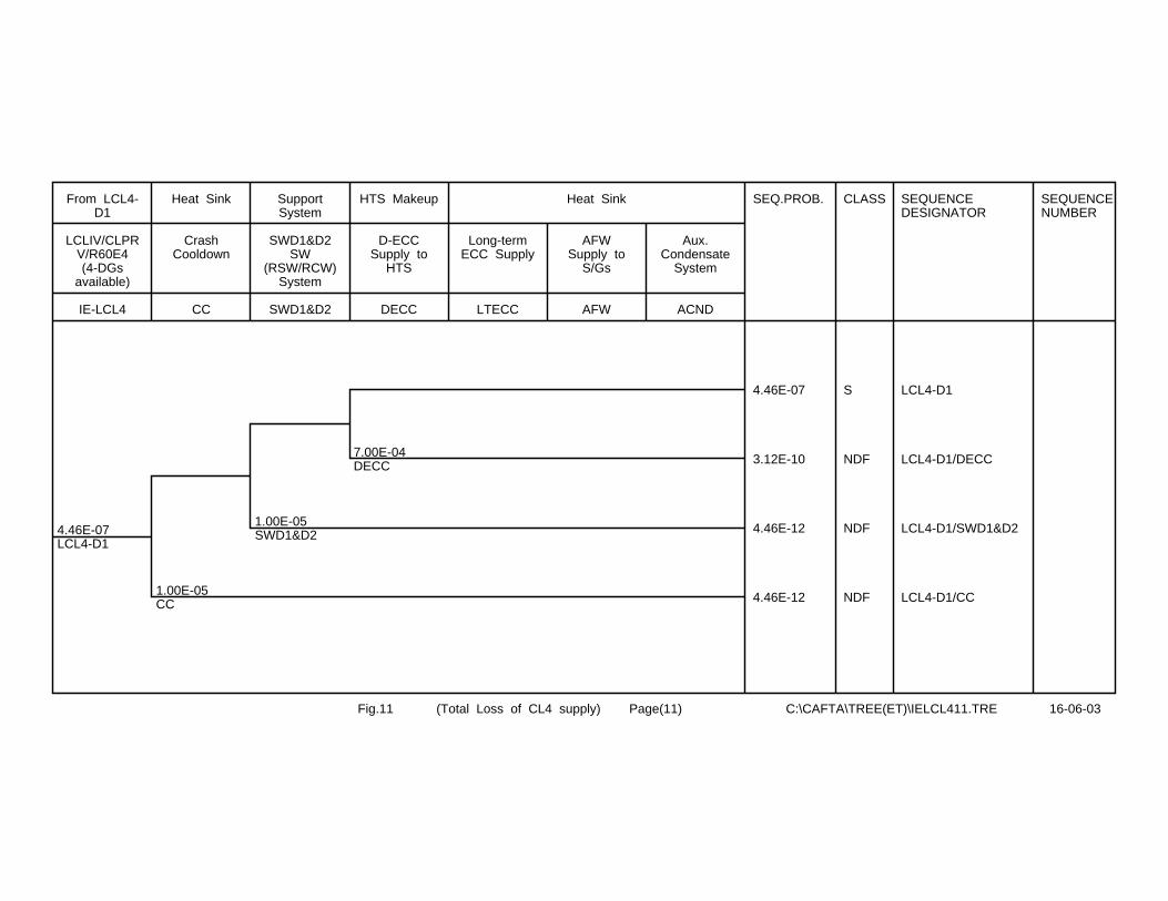
4.46E-07LCL4-D1
1.00E-05CC
1.00E-05SWD1&D2
7.00E-04DECC
SEQ.PROB. CLASS SEQUENCEDESIGNATOR
SEQUENCENUMBER
4.46E-07 S LCL4-D1
3.12E-10 NDF LCL4-D1/DECC
4.46E-12 NDF LCL4-D1/SWD1&D2
4.46E-12 NDF LCL4-D1/CC
IE-LCL4
LCLIV/CLPRV/R60E4(4-DGs
available)
From LCL4-D1
CC
CrashCooldown
Heat Sink
SWD1&D2
SWD1&D2SW
(RSW/RCW)System
SupportSystem
DECC
D-ECCSupply to
HTS
HTS Makeup
LTECC
Long-termECC Supply
AFW
AFWSupply to
S/Gs
ACND
Aux.Condensate
System
Heat Sink
Fig.11 (Total Loss of CL4 supply) Page(11) C:\CAFTA\TREE(ET)\IELCL411.TRE 16-06-03

2.99E-08LCL4-D2
1.00E-05CC
2.00E-03DECC
8.00E-03LTECC
1.00E-02AFW
5.00E-02ACND
SEQ.PROB. CLASS SEQUENCEDESIGNATOR
SEQUENCENUMBER
2.96E-08 S LCL4-D2
2.36E-10 S LCL4-D2/LTECC
2.27E-12 S LCL4-D2/LTECC/AFW
1.19E-13 NDF LCL4-D2/LTECC/AFW/ACND
5.98E-11 NDF LCL4-D2/DECC
2.99E-13 NDF LCL4-D2/CC
IE-LCL4
LCLIV/CLPRV/R60E4(3-
DGsavailable)
From LCL4-D2
CC
CrashCooldown
Heat Sink
SWD1&D2
SWD1&D2SW(RSW/RCW
) System
SupportSystem
DECC
EmergencyCore Cooling Supply
to HTS
HTS Makeup
LTECC
Long-termECC Supply
AFW
AFWSupply to
S/Gs
ACND
AuxiliaryCondensate
System
EFW
EFWSupply to
SGs
MHS
ModeratorActs as
Heat Sink
Heat Sink
Fig.12 (Total Loss of CL4 supply) Page(12) C:\CAFTA\TREE(ET)\IELCL412.TRE 16-06-03
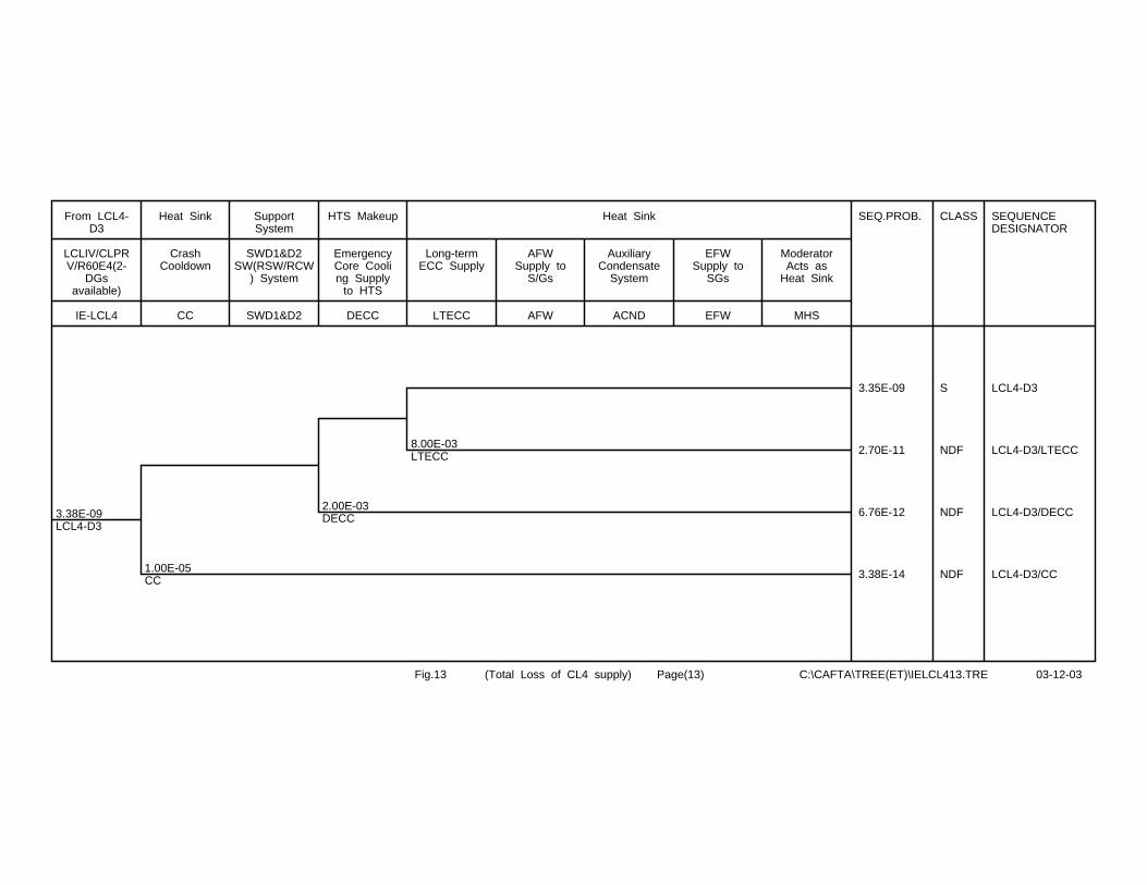
3.38E-09LCL4-D3
1.00E-05CC
2.00E-03DECC
8.00E-03LTECC
SEQ.PROB. CLASS SEQUENCEDESIGNATOR
3.35E-09 S LCL4-D3
2.70E-11 NDF LCL4-D3/LTECC
6.76E-12 NDF LCL4-D3/DECC
3.38E-14 NDF LCL4-D3/CC
IE-LCL4
LCLIV/CLPRV/R60E4(2-
DGsavailable)
From LCL4-D3
CC
CrashCooldown
Heat Sink
SWD1&D2
SWD1&D2SW(RSW/RCW
) System
SupportSystem
DECC
EmergencyCore Cooling Supply
to HTS
HTS Makeup
LTECC
Long-termECC Supply
AFW
AFWSupply to
S/Gs
ACND
AuxiliaryCondensate
System
EFW
EFWSupply to
SGs
MHS
ModeratorActs as
Heat Sink
Heat Sink
Fig.13 (Total Loss of CL4 supply) Page(13) C:\CAFTA\TREE(ET)\IELCL413.TRE 03-12-03
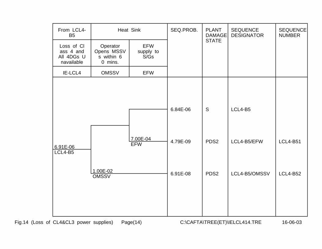
6.91E-06LCL4-B5
1.00E-02OMSSV
7.00E-04EFW
SEQ.PROB. PLANTDAMAGESTATE
SEQUENCEDESIGNATOR
SEQUENCENUMBER
6.84E-06 S LCL4-B5
4.79E-09 PDS2 LCL4-B5/EFW LCL4-B51
6.91E-08 PDS2 LCL4-B5/OMSSV LCL4-B52
IE-LCL4
Loss of Class 4 and
All 4DGs Unavailable
From LCL4-B5
OMSSV
OperatorOpens MSSV
s within 60 mins.
EFW
EFWsupply to
S/Gs
Heat Sink
Fig.14 (Loss of CL4&CL3 power supplies) Page(14) C:\CAFTA\TREE(ET)\IELCL414.TRE 16-06-03
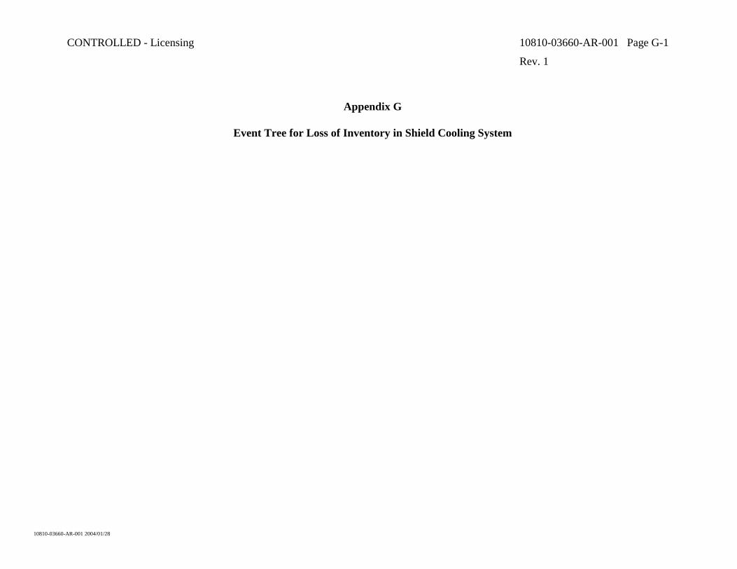
CONTROLLED - Licensing 10810-03660-AR-001 Page G-1
Rev. 1
10810-03660-AR-001 2004/01/28
Appendix G
Event Tree for Loss of Inventory in Shield Cooling System
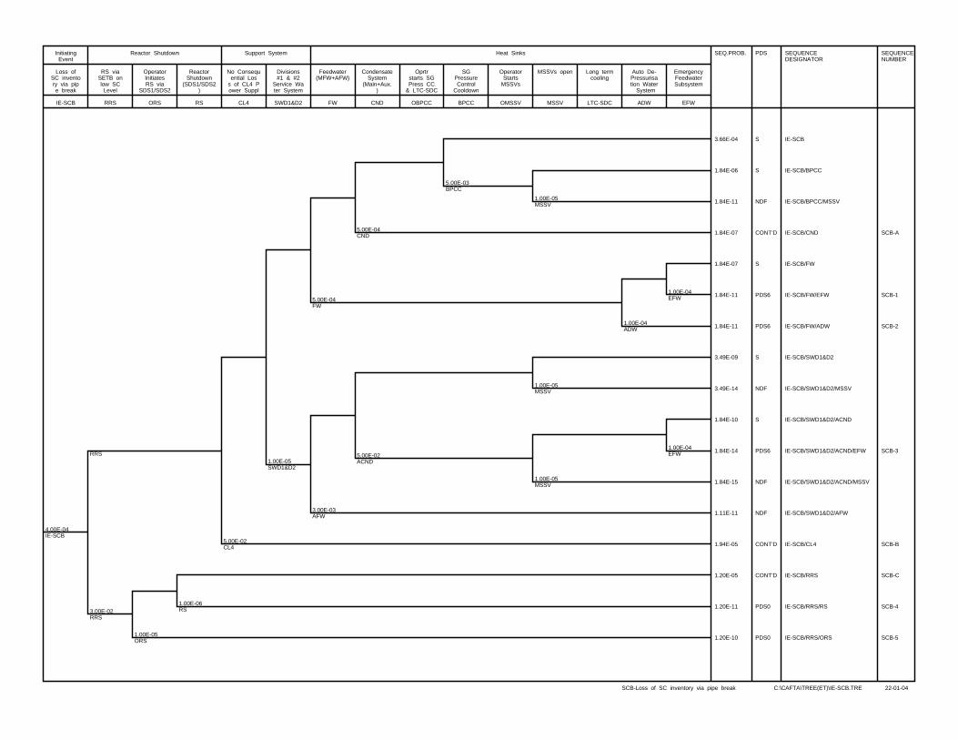
4.00E-04IE-SCB
RRS
3.00E-02RRS
1.00E-05ORS
1.00E-06RS
5.00E-02CL4
1.00E-05SWD1&D2
5.00E-04FW
3.00E-03AFW
5.00E-04CND
5.00E-02ACND
5.00E-03BPCC
1.00E-05MSSV
1.00E-05MSSV
1.00E-05MSSV
1.00E-04ADW
1.00E-04EFW
1.00E-04EFW
SEQ.PROB. PDS SEQUENCEDESIGNATOR
SEQUENCENUMBER
3.66E-04 S IE-SCB
1.84E-06 S IE-SCB/BPCC
1.84E-11 NDF IE-SCB/BPCC/MSSV
1.84E-07 CONT’D IE-SCB/CND SCB-A
1.84E-07 S IE-SCB/FW
1.84E-11 PDS6 IE-SCB/FW/EFW SCB-1
1.84E-11 PDS6 IE-SCB/FW/ADW SCB-2
3.49E-09 S IE-SCB/SWD1&D2
3.49E-14 NDF IE-SCB/SWD1&D2/MSSV
1.84E-10 S IE-SCB/SWD1&D2/ACND
1.84E-14 PDS6 IE-SCB/SWD1&D2/ACND/EFW SCB-3
1.84E-15 NDF IE-SCB/SWD1&D2/ACND/MSSV
1.11E-11 NDF IE-SCB/SWD1&D2/AFW
1.94E-05 CONT’D IE-SCB/CL4 SCB-B
1.20E-05 CONT’D IE-SCB/RRS SCB-C
1.20E-11 PDS0 IE-SCB/RRS/RS SCB-4
1.20E-10 PDS0 IE-SCB/RRS/ORS SCB-5
IE-SCB
Loss ofSC inventory via pipe break
InitiatingEvent
RRS
RS viaSETB onlow SCLevel
ORS
OperatorInitiatesRS via
SDS1/SDS2
RS
ReactorShutdown
(SDS1/SDS2)
Reactor Shutdown
CL4
No Consequential Los
s of CL4 Power Suppl
SWD1&D2
Divisions#1 & #2
Service Water System
Support System
FW
Feedwater(MFW+AFW)
CND
CondensateSystem
(Main+Aux.)
OBPCC
Oprtrstarts SGPress CC
& LTC-SDC
BPCC
SGPressureControl
Cooldown
OMSSV
OperatorStarts
MSSVs
MSSV
MSSVs open
LTC-SDC
Long termcooling
ADW
Auto De-Pressurisation Water System
EFW
EmergencyFeedwaterSubsystem
Heat Sinks
SCB-Loss of SC inventory via pipe break C:\CAFTA\TREE(ET)\IE-SCB.TRE 22-01-04
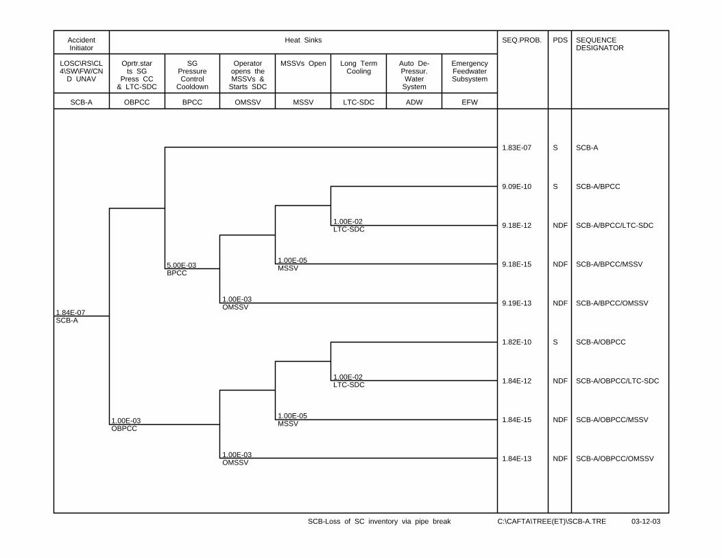
1.84E-07SCB-A
1.00E-03OBPCC
5.00E-03BPCC
1.00E-03OMSSV
1.00E-03OMSSV
1.00E-05MSSV
1.00E-05MSSV
1.00E-02LTC-SDC
1.00E-02LTC-SDC
SEQ.PROB. PDS SEQUENCEDESIGNATOR
1.83E-07 S SCB-A
9.09E-10 S SCB-A/BPCC
9.18E-12 NDF SCB-A/BPCC/LTC-SDC
9.18E-15 NDF SCB-A/BPCC/MSSV
9.19E-13 NDF SCB-A/BPCC/OMSSV
1.82E-10 S SCB-A/OBPCC
1.84E-12 NDF SCB-A/OBPCC/LTC-SDC
1.84E-15 NDF SCB-A/OBPCC/MSSV
1.84E-13 NDF SCB-A/OBPCC/OMSSV
SCB-A
LOSC\RS\CL4\SW\FW/CN
D UNAV
AccidentInitiator
OBPCC
Oprtr.starts SG
Press CC& LTC-SDC
BPCC
SGPressureControl
Cooldown
OMSSV
Operatoropens theMSSVs &
Starts SDC
MSSV
MSSVs Open
LTC-SDC
Long TermCooling
ADW
Auto De-Pressur.Water
System
EFW
EmergencyFeedwaterSubsystem
Heat Sinks
SCB-Loss of SC inventory via pipe break C:\CAFTA\TREE(ET)\SCB-A.TRE 03-12-03
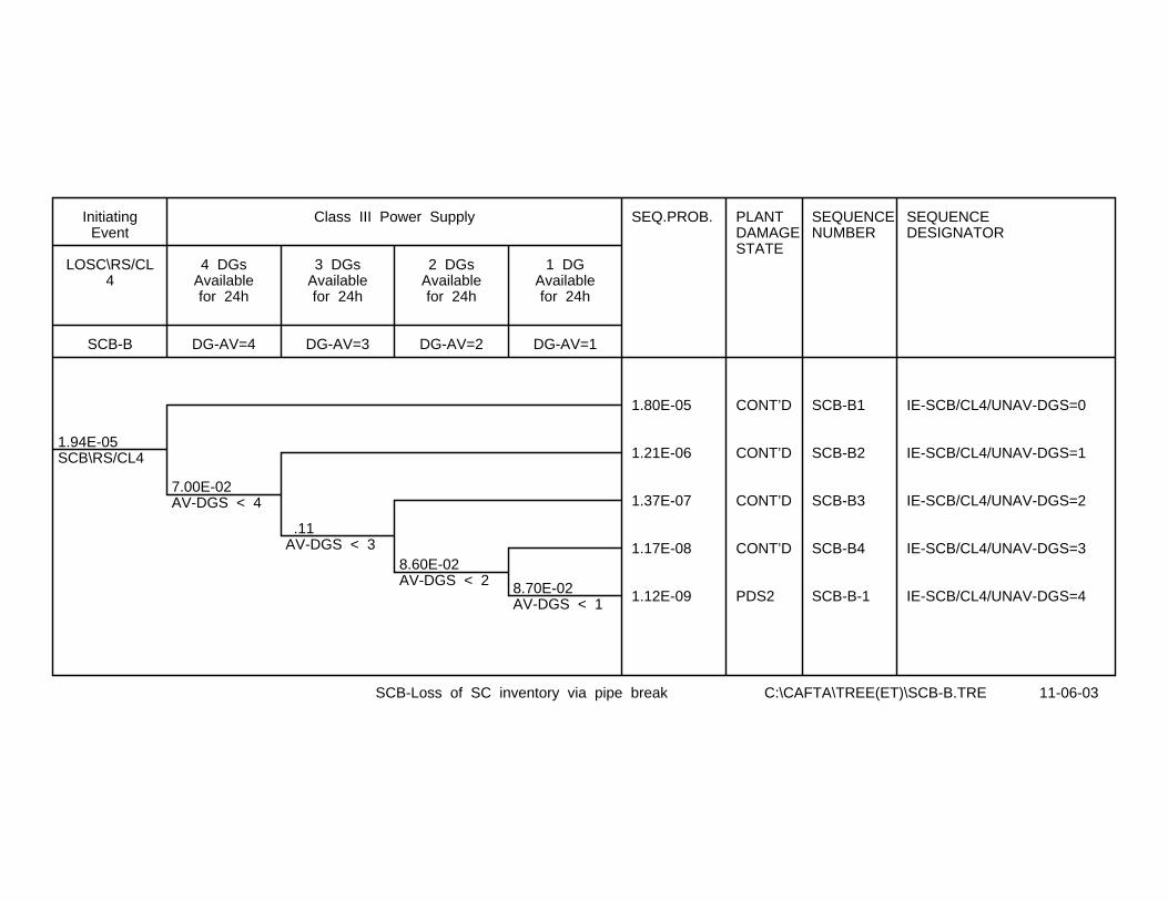
1.94E-05SCB\RS/CL4
7.00E-02AV-DGS < 4
.11AV-DGS < 3
8.60E-02AV-DGS < 2 8.70E-02
AV-DGS < 1
SEQ.PROB. PLANTDAMAGESTATE
SEQUENCENUMBER
SEQUENCEDESIGNATOR
1.80E-05 CONT’D SCB-B1 IE-SCB/CL4/UNAV-DGS=0
1.21E-06 CONT’D SCB-B2 IE-SCB/CL4/UNAV-DGS=1
1.37E-07 CONT’D SCB-B3 IE-SCB/CL4/UNAV-DGS=2
1.17E-08 CONT’D SCB-B4 IE-SCB/CL4/UNAV-DGS=3
1.12E-09 PDS2 SCB-B-1 IE-SCB/CL4/UNAV-DGS=4
SCB-B
LOSC\RS/CL4
InitiatingEvent
DG-AV=4
4 DGsAvailablefor 24h
DG-AV=3
3 DGsAvailablefor 24h
DG-AV=2
2 DGsAvailablefor 24h
DG-AV=1
1 DGAvailablefor 24h
Class III Power Supply
SCB-Loss of SC inventory via pipe break C:\CAFTA\TREE(ET)\SCB-B.TRE 11-06-03

1.80E-05SCB-B1
1.00E-05SWD1&D2
6.00E-03AFW
5.00E-02ACND
1.00E-03OMSSV
1.00E-05MSSV
1.00E-05MSSV
1.00E-02LTC-SDC
1.00E-02LTC-SDC
1.00E-04ADW
1.00E-04ADW
7.00E-04EFW
7.00E-04EFW
7.00E-04EFW
SEQ.PROB. PDS SEQUENCEDESIGNATOR
SEQUENCENUMBER
1.70E-05 S SCB-B1
1.68E-10 S SCB-B1/MSSV
1.70E-12 NDF SCB-B1/MSSV/LTC-SDC
8.85E-07 S SCB-B1/ACND
8.93E-09 S SCB-B1/ACND/LTC-SDC
6.26E-12 NDF SCB-B1/ACND/LTC-SDC/EFW
8.94E-12 NDF SCB-B1/ACND/MSSV
8.94E-10 S SCB-B1/ACND/OMSSV
6.26E-13 NDF SCB-B1/ACND/OMSSV/EFW
8.95E-14 NDF SCB-B1/ACND/OMSSV/ADW
1.08E-07 S SCB-B1/AFW
7.56E-11 PDS6 SCB-B1/AFW/EFW SCB-B1-1
1.08E-11 PDS6 SCB-B1/AFW/ADW SCB-B1-2
1.80E-10 NDF SCB-B1/SWD1&D2
SCB-B1
LOSC\RS/CL4\ALL DGS
AV
InitiatingEvent
SWD1&D2
Divisions#1 & #2
Service Water System
SupportSystem
AFW
AuxiliaryFeedwater
System
ACND
AuxiliaryCondensate
System
OBPCC
Oprtr.starts SG
Press CC& LTC-SDC
BPCC
SGPressureControl
Cooldown
OMSSV
Operatoropens the
MSSV & starts LTCSDC
MSSV
MSSVs Open
LTC-SDC
Long TermCooling
ADW
Auto De-Pressur.Water
System
EFW
EmergencyFeedwaterSubsystem
Heat Sinks
SCB-Loss of SC inventory via pipe break C:\CAFTA\TREE(ET)\SCB-B1.TRE 03-12-03
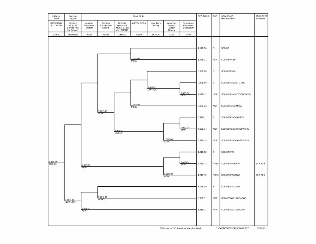
1.21E-06SCB-B2
1.00E-03SWD1&D2
1.00E-02AFW
1.00E-02AFW
5.00E-02ACND
5.00E-02ACND
1.00E-03OMSSV
1.00E-05MSSV
1.00E-05MSSV
5.00E-02LTC-SDC
1.00E-04ADW
1.00E-04ADW
7.00E-04EFW
7.00E-04EFW
7.00E-04EFW
SEQ.PROB. PDS SEQUENCEDESIGNATOR
SEQUENCENUMBER
1.14E-06 S SCB-B2
1.14E-11 NDF SCB-B2/MSSV
5.68E-08 S SCB-B2/ACND
2.99E-09 S SCB-B2/ACND/LTC-SDC
2.09E-12 NDF SCB-B2/ACND/LTC-SDC/EFW
5.98E-13 NDF SCB-B2/ACND/MSSV
5.98E-11 S SCB-B2/ACND/OMSSV
4.19E-14 NDF SCB-B2/ACND/OMSSV/EFW
5.98E-15 NDF SCB-B2/ACND/OMSSV/ADW
1.21E-08 S SCB-B2/AFW
8.46E-12 PDS6 SCB-B2/AFW/EFW SCB-B2-1
1.21E-12 PDS6 SCB-B2/AFW/ADW SCB-B2-2
1.14E-09 S SCB-B2/SWD1&D2
5.99E-11 NDF SCB-B2/SWD1&D2/ACND
1.21E-11 NDF SCB-B2/SWD1&D2/AFW
SCB-B2
LOSC\RS/CL4\1 DG UN
InitiatingEvent
SWD1&D2
Divisions#1 & #2
Service Water System
SupportSystem
AFW
AuxiliaryFeedwater
System
ACND
AuxiliaryCondensate
System
OMSSV
Operatoropens the
MSSV & starts LTCSDC
MSSV
MSSVs OPEN
LTC-SDC
Long TermCooling
ADW
Auto De-Pressur.Water
System
EFW
EmergencyFeedwaterSubsystem
Heat Sinks
SCB-Loss of SC inventory via pipe break C:\CAFTA\TREE(ET)\SCB-B2.TRE 03-12-03
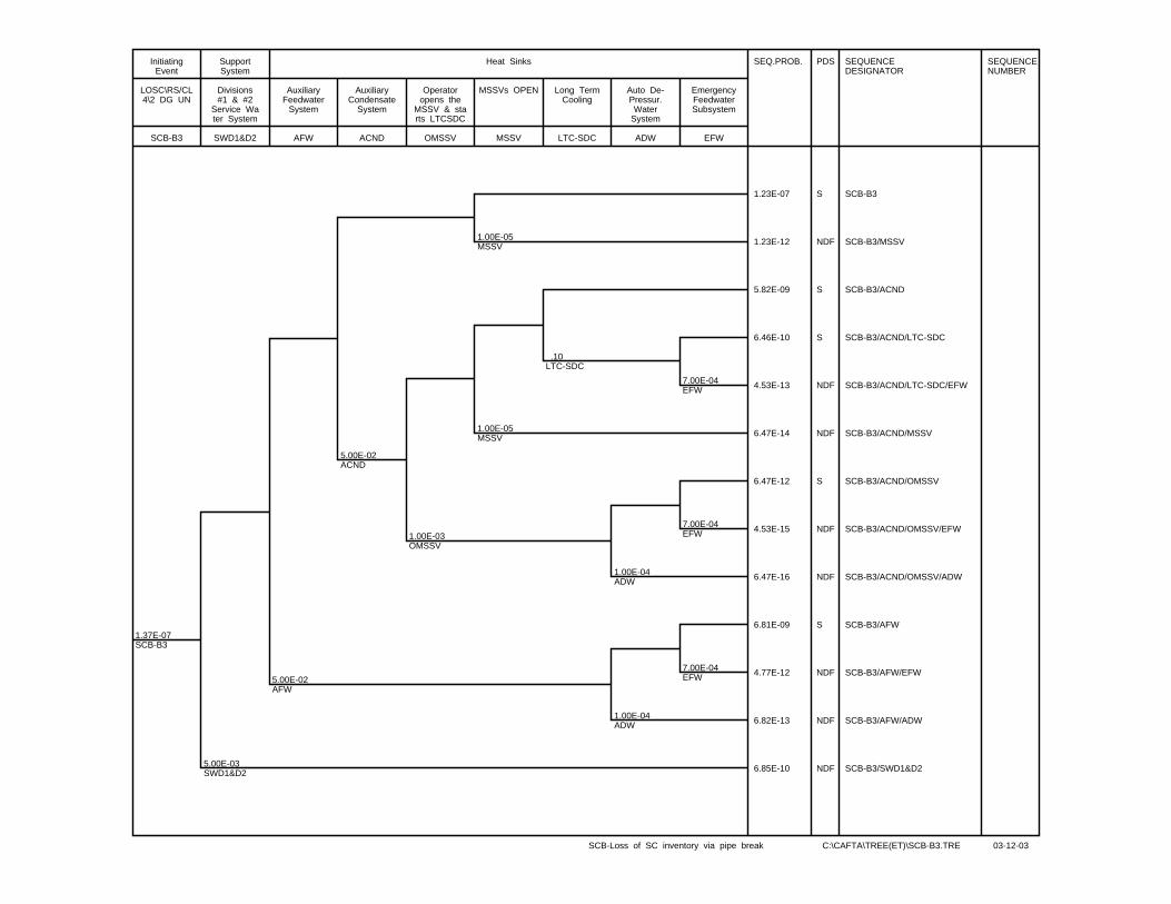
1.37E-07SCB-B3
5.00E-03SWD1&D2
5.00E-02AFW
5.00E-02ACND
1.00E-03OMSSV
1.00E-05MSSV
1.00E-05MSSV
.10LTC-SDC
1.00E-04ADW
1.00E-04ADW
7.00E-04EFW
7.00E-04EFW
7.00E-04EFW
SEQ.PROB. PDS SEQUENCEDESIGNATOR
SEQUENCENUMBER
1.23E-07 S SCB-B3
1.23E-12 NDF SCB-B3/MSSV
5.82E-09 S SCB-B3/ACND
6.46E-10 S SCB-B3/ACND/LTC-SDC
4.53E-13 NDF SCB-B3/ACND/LTC-SDC/EFW
6.47E-14 NDF SCB-B3/ACND/MSSV
6.47E-12 S SCB-B3/ACND/OMSSV
4.53E-15 NDF SCB-B3/ACND/OMSSV/EFW
6.47E-16 NDF SCB-B3/ACND/OMSSV/ADW
6.81E-09 S SCB-B3/AFW
4.77E-12 NDF SCB-B3/AFW/EFW
6.82E-13 NDF SCB-B3/AFW/ADW
6.85E-10 NDF SCB-B3/SWD1&D2
SCB-B3
LOSC\RS/CL4\2 DG UN
InitiatingEvent
SWD1&D2
Divisions#1 & #2
Service Water System
SupportSystem
AFW
AuxiliaryFeedwater
System
ACND
AuxiliaryCondensate
System
OMSSV
Operatoropens the
MSSV & starts LTCSDC
MSSV
MSSVs OPEN
LTC-SDC
Long TermCooling
ADW
Auto De-Pressur.Water
System
EFW
EmergencyFeedwaterSubsystem
Heat Sinks
SCB-Loss of SC inventory via pipe break C:\CAFTA\TREE(ET)\SCB-B3.TRE 03-12-03

1.17E-08SCB-B4
1.00E-02SWD1&D2
.10AFW
5.00E-02ACND
1.00E-03OMSSV
1.00E-05MSSV
1.00E-05MSSV
.50LTC-SDC
1.00E-04ADW
7.00E-04EFW
7.00E-04EFW
SEQ.PROB. PDS SEQUENCEDESIGNATOR
9.90E-09 S SCB-B4
9.90E-14 NDF SCB-B4/MSSV
2.60E-10 S SCB-B4/ACND
2.60E-10 S SCB-B4/ACND/LTC-SDC
1.82E-13 NDF SCB-B4/ACND/LTC-SDC/EFW
5.21E-15 NDF SCB-B4/ACND/MSSV
5.21E-13 NDF SCB-B4/ACND/OMSSV
1.16E-09 S SCB-B4/AFW
8.11E-13 NDF SCB-B4/AFW/EFW
1.16E-13 NDF SCB-B4/AFW/ADW
1.17E-10 NDF SCB-B4/SWD1&D2
SCB-B4
LOSC\RS/CL4\ 3 DG UN
InitiatingEvent
SWD1&D2
Divisions#1 & #2
Service Water System
SupportSystem
AFW
AuxiliaryFeedwater
System
ACND
AuxiliaryCondensate
System
OMSSV
Operatoropens the
MSSV & starts LTCSDC
MSSV
MSSVs Open
LTC-SDC
Long TermCooling
ADW
Auto De-Pressur.Water
System
EFW
EmergencyFeedwaterSubsystem
Heat Sinks
SCB-Loss of SC inventory via pipe break C:\CAFTA\TREE(ET)\SCB-B4.TRE 03-12-03
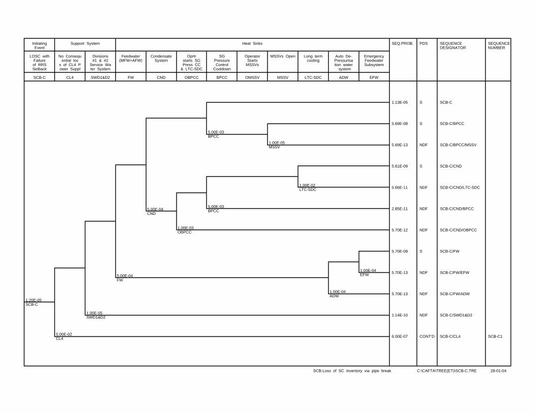
1.20E-05SCB-C
5.00E-02CL4
1.00E-05SWD1&D2
5.00E-04FW
5.00E-04CND
1.00E-03OBPCC
5.00E-03BPCC
5.00E-03BPCC
1.00E-05MSSV
1.00E-02LTC-SDC
1.00E-04ADW
1.00E-04EFW
SEQ.PROB. PDS SEQUENCEDESIGNATOR
SEQUENCENUMBER
1.13E-05 S SCB-C
5.69E-08 S SCB-C/BPCC
5.69E-13 NDF SCB-C/BPCC/MSSV
5.61E-09 S SCB-C/CND
5.66E-11 NDF SCB-C/CND/LTC-SDC
2.85E-11 NDF SCB-C/CND/BPCC
5.70E-12 NDF SCB-C/CND/OBPCC
5.70E-09 S SCB-C/FW
5.70E-13 NDF SCB-C/FW/EFW
5.70E-13 NDF SCB-C/FW/ADW
1.14E-10 NDF SCB-C/SWD1&D2
6.00E-07 CONT’D SCB-C/CL4 SCB-C1
SCB-C
LOSC withFailureof RRSSetback
InitiatingEvent
CL4
No Consequential los
s of CL4 Power Suppl
SWD1&D2
Divisions#1 & #2
Service Water System
Support System
FW
Feedwater(MFW+AFW)
CND
CondensateSystem
OBPCC
Oprtrstarts SGPress CC
& LTC-SDC
BPCC
SGPressureControl
Cooldown
OMSSV
OperatorStarts
MSSVs
MSSV
MSSVs Open
LTC-SDC
Long termcooling
ADW
Auto De-Pressurisation water system
EFW
EmergencyFeedwaterSubsystem
Heat Sinks
SCB-Loss of SC inventory via pipe break C:\CAFTA\TREE(ET)\SCB-C.TRE 28-01-04
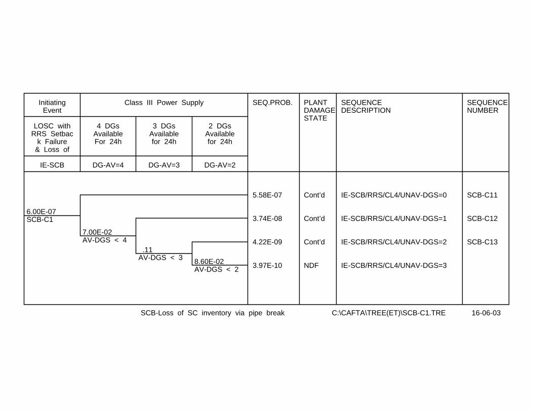
6.00E-07SCB-C1
7.00E-02AV-DGS < 4
.11AV-DGS < 3 8.60E-02
AV-DGS < 2
SEQ.PROB. PLANTDAMAGESTATE
SEQUENCEDESCRIPTION
SEQUENCENUMBER
5.58E-07 Cont’d IE-SCB/RRS/CL4/UNAV-DGS=0 SCB-C11
3.74E-08 Cont’d IE-SCB/RRS/CL4/UNAV-DGS=1 SCB-C12
4.22E-09 Cont’d IE-SCB/RRS/CL4/UNAV-DGS=2 SCB-C13
3.97E-10 NDF IE-SCB/RRS/CL4/UNAV-DGS=3
IE-SCB
LOSC withRRS Setbac
k Failure& Loss of
InitiatingEvent
DG-AV=4
4 DGsAvailableFor 24h
DG-AV=3
3 DGsAvailablefor 24h
DG-AV=2
2 DGsAvailablefor 24h
Class III Power Supply
SCB-Loss of SC inventory via pipe break C:\CAFTA\TREE(ET)\SCB-C1.TRE 16-06-03
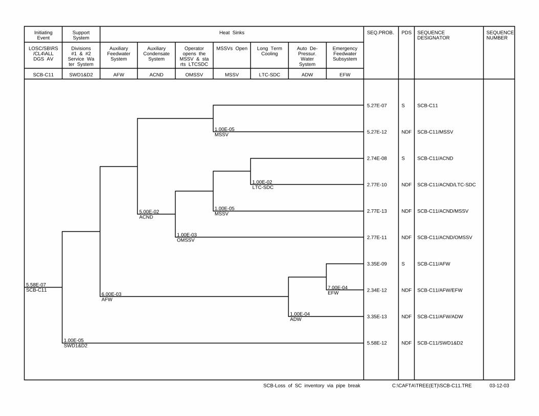
5.58E-07SCB-C11
1.00E-05SWD1&D2
6.00E-03AFW
5.00E-02ACND
1.00E-03OMSSV
1.00E-05MSSV
1.00E-05MSSV
1.00E-02LTC-SDC
1.00E-04ADW
7.00E-04EFW
SEQ.PROB. PDS SEQUENCEDESIGNATOR
SEQUENCENUMBER
5.27E-07 S SCB-C11
5.27E-12 NDF SCB-C11/MSSV
2.74E-08 S SCB-C11/ACND
2.77E-10 NDF SCB-C11/ACND/LTC-SDC
2.77E-13 NDF SCB-C11/ACND/MSSV
2.77E-11 NDF SCB-C11/ACND/OMSSV
3.35E-09 S SCB-C11/AFW
2.34E-12 NDF SCB-C11/AFW/EFW
3.35E-13 NDF SCB-C11/AFW/ADW
5.58E-12 NDF SCB-C11/SWD1&D2
SCB-C11
LOSC/SB\RS/CL4\ALLDGS AV
InitiatingEvent
SWD1&D2
Divisions#1 & #2
Service Water System
SupportSystem
AFW
AuxiliaryFeedwater
System
ACND
AuxiliaryCondensate
System
OMSSV
Operatoropens the
MSSV & starts LTCSDC
MSSV
MSSVs Open
LTC-SDC
Long TermCooling
ADW
Auto De-Pressur.Water
System
EFW
EmergencyFeedwaterSubsystem
Heat Sinks
SCB-Loss of SC inventory via pipe break C:\CAFTA\TREE(ET)\SCB-C11.TRE 03-12-03

3.74E-08SCB-C12
1.00E-03SWD1&D2
1.00E-02AFW
5.00E-02ACND
1.00E-03OMSSV
1.00E-05MSSV
1.00E-05MSSV
5.00E-02LTC-SDC
1.00E-04ADW
7.00E-04EFW
7.00E-04EFW
SEQ.PROB. PDS SEQUENCEDESIGNATOR
3.51E-08 S SCB-C12
3.51E-13 NDF SCB-C12/MSSV
1.76E-09 S SCB-C12/ACND
9.23E-11 S SCB-C12/ACND/LTC-SDC
6.47E-14 NDF SCB-C12/ACND/LTC-SDC/EFW
1.85E-14 NDF SCB-C12/ACND/MSSV
1.85E-12 NDF SCB-C12/ACND/OMSSV
3.73E-10 S SCB-C12/AFW
2.62E-13 NDF SCB-C12/AFW/EFW
3.74E-14 NDF SCB-C12/AFW/ADW
3.74E-11 NDF SCB-C12/SWD1&D2
SCB-C12
LOSC/SB\RS/CL4\1 DG
UN
SWD1&D2
Divisions#1 & #2
Service Water System
SupportSystem
AFW
AuxiliaryFeedwater
System
ACND
AuxiliaryCondensate
System
OMSSV
Operatoropens the
MSSV & starts LTCSDC
MSSV
MSSVs Open
LTC-SDC
Long TermCooling
ADW
Auto De-Pressur.Water
System
EFW
EmergencyFeedwaterSubsystem
Heat Sinks
SCB-Loss of SC inventory via pipe break C:\CAFTA\TREE(ET)\SCB-C12.TRE 03-12-03
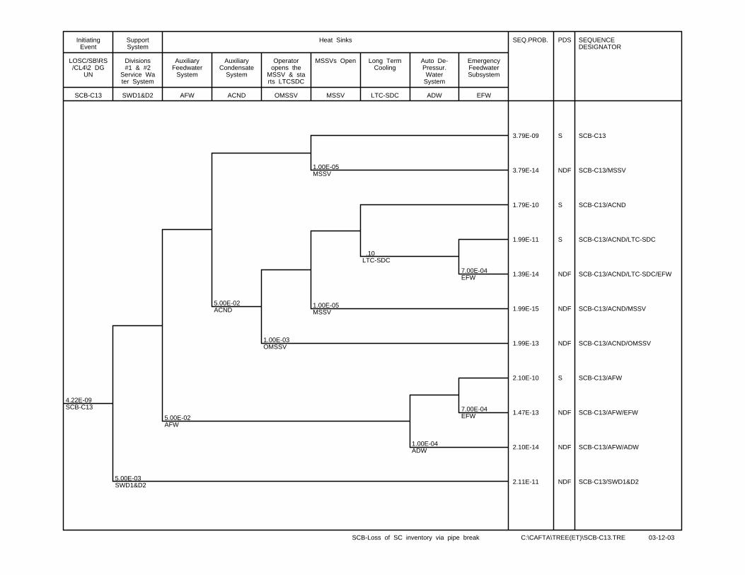
4.22E-09SCB-C13
5.00E-03SWD1&D2
5.00E-02AFW
5.00E-02ACND
1.00E-03OMSSV
1.00E-05MSSV
1.00E-05MSSV
.10LTC-SDC
1.00E-04ADW
7.00E-04EFW
7.00E-04EFW
SEQ.PROB. PDS SEQUENCEDESIGNATOR
3.79E-09 S SCB-C13
3.79E-14 NDF SCB-C13/MSSV
1.79E-10 S SCB-C13/ACND
1.99E-11 S SCB-C13/ACND/LTC-SDC
1.39E-14 NDF SCB-C13/ACND/LTC-SDC/EFW
1.99E-15 NDF SCB-C13/ACND/MSSV
1.99E-13 NDF SCB-C13/ACND/OMSSV
2.10E-10 S SCB-C13/AFW
1.47E-13 NDF SCB-C13/AFW/EFW
2.10E-14 NDF SCB-C13/AFW/ADW
2.11E-11 NDF SCB-C13/SWD1&D2
SCB-C13
LOSC/SB\RS/CL4\2 DG
UN
InitiatingEvent
SWD1&D2
Divisions#1 & #2
Service Water System
SupportSystem
AFW
AuxiliaryFeedwater
System
ACND
AuxiliaryCondensate
System
OMSSV
Operatoropens the
MSSV & starts LTCSDC
MSSV
MSSVs Open
LTC-SDC
Long TermCooling
ADW
Auto De-Pressur.Water
System
EFW
EmergencyFeedwaterSubsystem
Heat Sinks
SCB-Loss of SC inventory via pipe break C:\CAFTA\TREE(ET)\SCB-C13.TRE 03-12-03

CONTROLLED - Licensing 10810-03660-AR-001 Page H-1
Rev. 1
10810-03660-AR-001 2004/01/28
Appendix H
Event Tree for Small Steam Line Break Causing Low Level in the Deaerator

.10IE-MSL3
5.00E-04CND
1.00E-03ORS
5.00E-02RRS-SETB
5.00E-02RRS-SETB
1.00E-06SDS1/SDS2
1.00E-06SDS1/SDS2
5.00E-02CL4
5.00E-02CL4
1.00E-04ADW
1.00E-04ADW
1.00E-04EFW
1.00E-04EFW
SEQ.PROB. PLANTDAMAGESTATE
SEQUENCEDESIGNATOR
SEQUENCENUMBER
9.99E-02 CONT’D IE-MSL3 MSL3-A
9.50E-05 CONT’D IE-MSL3/ORS MSL3-B
4.75E-06 S IE-MSL3/ORS/RRS-SETB
4.75E-10 NDF IE-MSL3/ORS/RRS-SETB/EFW
4.75E-10 NDF IE-MSL3/ORS/RRS-SETB/ADW
2.50E-07 CONT’D IE-MSL3/ORS/RRS-SETB/CL4 MSL3-C
5.00E-12 PDS0 IE-MSL3/ORS/RRS-SETB/SDS1/SDS2 MSL3-1
4.75E-05 CONT’D IE-MSL3/CND MSL3-D
2.37E-06 S IE-MSL3/CND/RRS-SETB
2.37E-10 NDF IE-MSL3/CND/RRS-SETB/EFW
2.37E-10 NDF IE-MSL3/CND/RRS-SETB/ADW
1.25E-07 CONT’D IE-MSL3/CND/RRS-SETB/CL4 MSL3-E
2.50E-12 PDS0 IE-MSL3/CND/RRS-SETB/SDS1/SDS2 MSL3-2
IE-MSL3
SMALL STEAMLINE BREAK/(Small Steam Disch.-Leak)
InitiatingEvent
CND
CONDENSATESYSTEM
Heat Sink
ORS
OP SHUTS DOWN THE REACTOR
IN 60min (4hInventory)
OperatorAction
RRS-SETB
SETBACK ONLOW
DEAERATORLEVEL
SDS1/SDS2
SDS1 /SDS2Shutdown on
LFWLP or LSGL
Reactor Shutdown
CL4
NoConsequential
Loss ofClass 4 Power
SupportSystem
FW
FEEDWATERSYSTEM (MFW
+ AFW)
ADW
SG Auto-Depres.+Automatic
EFW Actuation
EFW
EmergencyFeedwaterSubystem
Heat Sinks
SMALL STEAM LINE BREAK CAUSING LOW DEAERATOR LEVEL C:\CAFTA\TREE(ET)\IE-MSL3.TRE 23-01-04
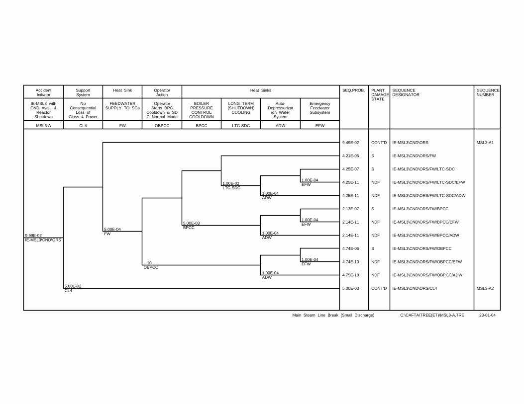
9.99E-02IE-MSL3\CND\ORS
5.00E-02CL4
5.00E-04FW
.10OBPCC
5.00E-03BPCC
1.00E-02LTC-SDC
1.00E-04ADW
1.00E-04ADW
1.00E-04ADW
1.00E-04EFW
1.00E-04EFW
1.00E-04EFW
SEQ.PROB. PLANTDAMAGESTATE
SEQUENCEDESIGNATOR
SEQUENCENUMBER
9.49E-02 CONT’D IE-MSL3\CND\ORS MSL3-A1
4.21E-05 S IE-MSL3\CND\ORS/FW
4.25E-07 S IE-MSL3\CND\ORS/FW/LTC-SDC
4.25E-11 NDF IE-MSL3\CND\ORS/FW/LTC-SDC/EFW
4.25E-11 NDF IE-MSL3\CND\ORS/FW/LTC-SDC/ADW
2.13E-07 S IE-MSL3\CND\ORS/FW/BPCC
2.14E-11 NDF IE-MSL3\CND\ORS/FW/BPCC/EFW
2.14E-11 NDF IE-MSL3\CND\ORS/FW/BPCC/ADW
4.74E-06 S IE-MSL3\CND\ORS/FW/OBPCC
4.74E-10 NDF IE-MSL3\CND\ORS/FW/OBPCC/EFW
4.75E-10 NDF IE-MSL3\CND\ORS/FW/OBPCC/ADW
5.00E-03 CONT’D IE-MSL3\CND\ORS/CL4 MSL3-A2
MSL3-A
IE-MSL3 withCND Avail. &
ReactorShutdown
AccidentInitiator
CL4
NoConsequential
Loss ofClass 4 Power
SupportSystem
FW
FEEDWATERSUPPLY TO SGs
Heat Sink
OBPCC
OperatorStarts BPC
Cooldown & SDC Normal Mode
OperatorAction
BPCC
BOILERPRESSURECONTROL
COOLDOWN
LTC-SDC
LONG TERM(SHUTDOWN)
COOLING
ADW
Auto-Depressurizat
ion WaterSystem
EFW
EmergencyFeedwaterSubsystem
Heat Sinks
Main Steam Line Break (Small Discharge) C:\CAFTA\TREE(ET)\MSL3-A.TRE 23-01-04
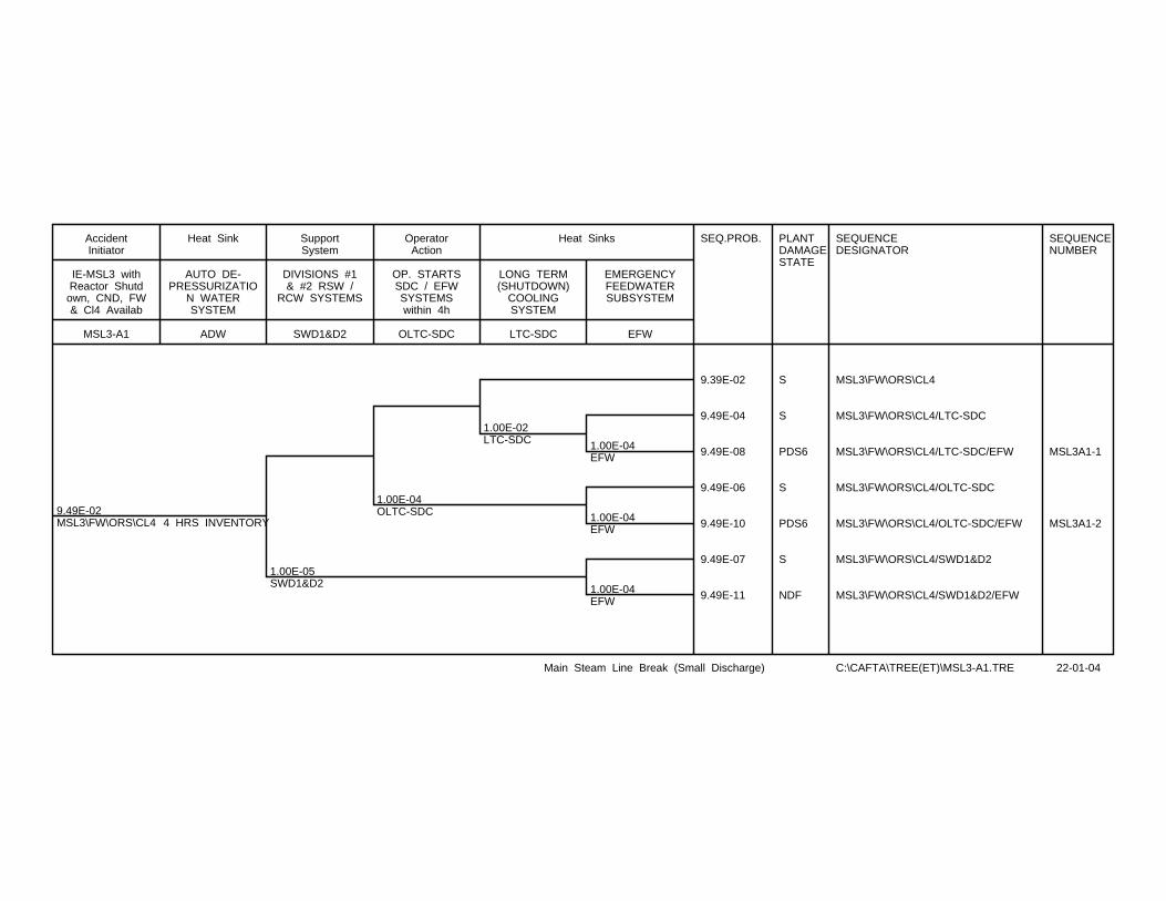
9.49E-02MSL3\FW\ORS\CL4 4 HRS INVENTORY
1.00E-05SWD1&D2
1.00E-04OLTC-SDC
1.00E-02LTC-SDC 1.00E-04
EFW
1.00E-04EFW
1.00E-04EFW
SEQ.PROB. PLANTDAMAGESTATE
SEQUENCEDESIGNATOR
SEQUENCENUMBER
9.39E-02 S MSL3\FW\ORS\CL4
9.49E-04 S MSL3\FW\ORS\CL4/LTC-SDC
9.49E-08 PDS6 MSL3\FW\ORS\CL4/LTC-SDC/EFW MSL3A1-1
9.49E-06 S MSL3\FW\ORS\CL4/OLTC-SDC
9.49E-10 PDS6 MSL3\FW\ORS\CL4/OLTC-SDC/EFW MSL3A1-2
9.49E-07 S MSL3\FW\ORS\CL4/SWD1&D2
9.49E-11 NDF MSL3\FW\ORS\CL4/SWD1&D2/EFW
MSL3-A1
IE-MSL3 withReactor Shutdown, CND, FW& Cl4 Availab
AccidentInitiator
ADW
AUTO DE-PRESSURIZATIO
N WATERSYSTEM
Heat Sink
SWD1&D2
DIVISIONS #1& #2 RSW /
RCW SYSTEMS
SupportSystem
OLTC-SDC
OP. STARTSSDC / EFWSYSTEMSwithin 4h
OperatorAction
LTC-SDC
LONG TERM(SHUTDOWN)
COOLINGSYSTEM
EFW
EMERGENCYFEEDWATERSUBSYSTEM
Heat Sinks
Main Steam Line Break (Small Discharge) C:\CAFTA\TREE(ET)\MSL3-A1.TRE 22-01-04
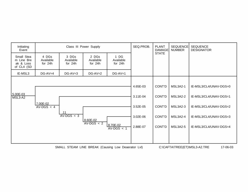
5.00E-03MSL3-A2
7.00E-02AV-DGS < 4
.11AV-DGS < 3
8.60E-02AV-DGS < 2 8.70E-02
AV-DGS < 1
SEQ.PROB. PLANTDAMAGESTATE
SEQUENCENUMBER
SEQUENCEDESIGNATOR
4.65E-03 CONT’D MSL3A2-1 IE-MSL3/CL4/UNAV-DGS=0
3.11E-04 CONT’D MSL3A2-2 IE-MSL3/CL4/UNAV-DGS=1
3.52E-05 CONT’D MSL3A2-3 IE-MSL3/CL4/UNAV-DGS=2
3.02E-06 CONT’D MSL3A2-4 IE-MSL3/CL4/UNAV-DGS=3
2.88E-07 CONT’D MSL3A2-5 IE-MSL3/CL4/UNAV-DGS=4
IE-MSL3
Small Steam Line Break & Lossof CL4 (SD
InitiatingEvent
DG-AV=4
4 DGsAvailablefor 24h
DG-AV=3
3 DGsAvailablefor 24h
DG-AV=2
2 DGsAvailablefor 24h
DG-AV=1
1 DGAvailablefor 24h
Class III Power Supply
SMALL STEAM LINE BREAK (Causing Low Deaerator Lvl) C:\CAFTA\TREE(ET)\MSL3-A2.TRE 17-06-03
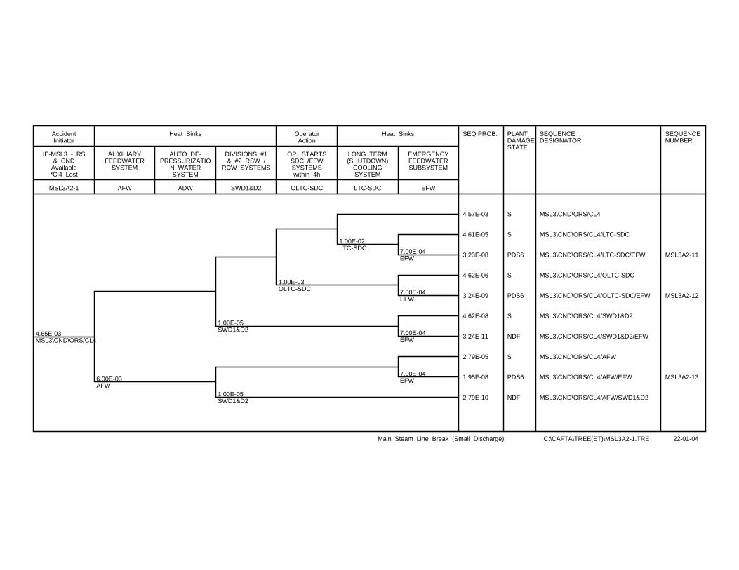
4.65E-03MSL3\CND\ORS/CL4
6.00E-03AFW
1.00E-05SWD1&D2
1.00E-05SWD1&D2
1.00E-03OLTC-SDC
1.00E-02LTC-SDC 7.00E-04
EFW
7.00E-04EFW
7.00E-04EFW
7.00E-04EFW
SEQ.PROB. PLANTDAMAGESTATE
SEQUENCEDESIGNATOR
SEQUENCENUMBER
4.57E-03 S MSL3\CND\ORS/CL4
4.61E-05 S MSL3\CND\ORS/CL4/LTC-SDC
3.23E-08 PDS6 MSL3\CND\ORS/CL4/LTC-SDC/EFW MSL3A2-11
4.62E-06 S MSL3\CND\ORS/CL4/OLTC-SDC
3.24E-09 PDS6 MSL3\CND\ORS/CL4/OLTC-SDC/EFW MSL3A2-12
4.62E-08 S MSL3\CND\ORS/CL4/SWD1&D2
3.24E-11 NDF MSL3\CND\ORS/CL4/SWD1&D2/EFW
2.79E-05 S MSL3\CND\ORS/CL4/AFW
1.95E-08 PDS6 MSL3\CND\ORS/CL4/AFW/EFW MSL3A2-13
2.79E-10 NDF MSL3\CND\ORS/CL4/AFW/SWD1&D2
MSL3A2-1
IE-MSL3 - RS& CND
Available*Cl4 Lost
AccidentInitiator
AFW
AUXILIARYFEEDWATER
SYSTEM
ADW
AUTO DE-PRESSURIZATIO
N WATERSYSTEM
SWD1&D2
DIVISIONS #1& #2 RSW /
RCW SYSTEMS
Heat Sinks
OLTC-SDC
OP. STARTSSDC /EFWSYSTEMSwithin 4h
OperatorAction
LTC-SDC
LONG TERM(SHUTDOWN)
COOLINGSYSTEM
EFW
EMERGENCYFEEDWATERSUBSYSTEM
Heat Sinks
Main Steam Line Break (Small Discharge) C:\CAFTA\TREE(ET)\MSL3A2-1.TRE 22-01-04

3.11E-04MSL3\CND\ORS/CL4
1.00E-02AFW
1.00E-03SWD1&D2
1.00E-03SWD1&D2
1.00E-03OLTC-SDC
5.00E-02LTC-SDC 7.00E-04
EFW
7.00E-04EFW
7.00E-04EFW
7.00E-04EFW
7.00E-04EFW
SEQ.PROB. PLANTDAMAGESTATE
SEQUENCEDESIGNATOR
SEQUENCENUMBER
2.92E-04 S MSL3\CND\ORS/CL4
1.54E-05 S MSL3\CND\ORS/CL4/LTC-SDC
1.08E-08 PDS6 MSL3\CND\ORS/CL4/LTC-SDC/EFW MSL3A2-21
3.07E-07 S MSL3\CND\ORS/CL4/OLTC-SDC
2.15E-10 NDF MSL3\CND\ORS/CL4/OLTC-SDC/EFW
3.08E-07 S MSL3\CND\ORS/CL4/SWD1&D2
2.16E-10 NDF MSL3\CND\ORS/CL4/SWD1&D2/EFW
3.10E-06 S MSL3\CND\ORS/CL4/AFW
2.17E-09 PDS6 MSL3\CND\ORS/CL4/AFW/EFW MSL3A2-22
3.11E-09 S MSL3\CND\ORS/CL4/AFW/SWD1&D2
2.18E-12 NDF MSL3\CND\ORS/CL4/AFW/SWD1&D2/EFW
MSL3A2-2
IE-MSL3 - RS& CND Available *Cl4 & 1
DG Lost
AccidentInitiator
AFW
AUXILIARYFEEDWATER
SYSTEM
ADW
AUTO DE-PRESSURIZATIO
N WATERSYSTEM
Heat Sinks
SWD1&D2
DIVISIONS #1& #2 RSW /
RCW SYSTEMS
SupportSystem
OLTC-SDC
OP. STARTSSDC /EFWSYSTEMSAFTER 4h
OperatorAction
LTC-SDC
SHUTDOWNCOOLINGSYSTEM
EFW
EMERGENCYFEEDWATERSUBSYSTEM
Heat Sinks
Main Steam Line Break (Small Discharge) C:\CAFTA\TREE(ET)\MSL3A2-2.TRE 22-01-04
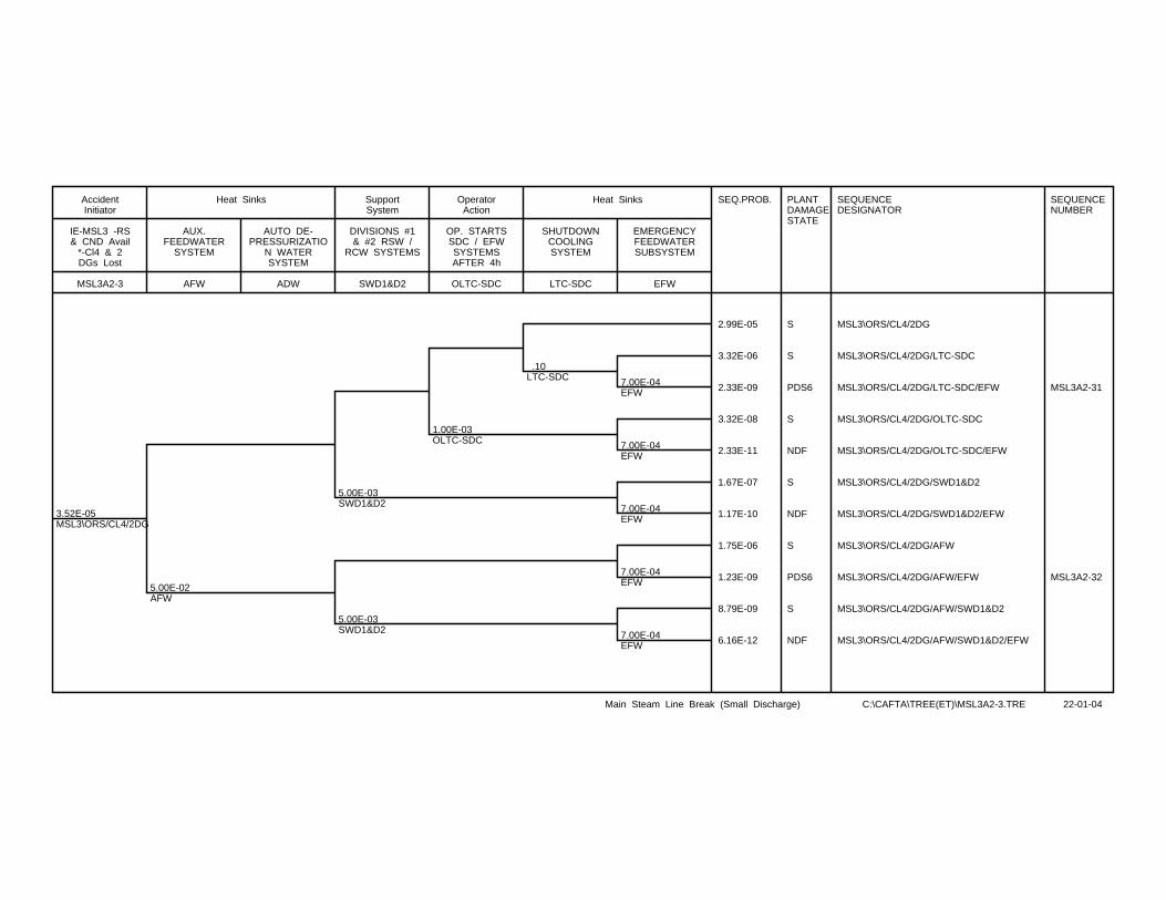
3.52E-05MSL3\ORS/CL4/2DG
5.00E-02AFW
5.00E-03SWD1&D2
5.00E-03SWD1&D2
1.00E-03OLTC-SDC
.10LTC-SDC 7.00E-04
EFW
7.00E-04EFW
7.00E-04EFW
7.00E-04EFW
7.00E-04EFW
SEQ.PROB. PLANTDAMAGESTATE
SEQUENCEDESIGNATOR
SEQUENCENUMBER
2.99E-05 S MSL3\ORS/CL4/2DG
3.32E-06 S MSL3\ORS/CL4/2DG/LTC-SDC
2.33E-09 PDS6 MSL3\ORS/CL4/2DG/LTC-SDC/EFW MSL3A2-31
3.32E-08 S MSL3\ORS/CL4/2DG/OLTC-SDC
2.33E-11 NDF MSL3\ORS/CL4/2DG/OLTC-SDC/EFW
1.67E-07 S MSL3\ORS/CL4/2DG/SWD1&D2
1.17E-10 NDF MSL3\ORS/CL4/2DG/SWD1&D2/EFW
1.75E-06 S MSL3\ORS/CL4/2DG/AFW
1.23E-09 PDS6 MSL3\ORS/CL4/2DG/AFW/EFW MSL3A2-32
8.79E-09 S MSL3\ORS/CL4/2DG/AFW/SWD1&D2
6.16E-12 NDF MSL3\ORS/CL4/2DG/AFW/SWD1&D2/EFW
MSL3A2-3
IE-MSL3 -RS& CND Avail
*-Cl4 & 2DGs Lost
AccidentInitiator
AFW
AUX.FEEDWATER
SYSTEM
ADW
AUTO DE-PRESSURIZATIO
N WATERSYSTEM
Heat Sinks
SWD1&D2
DIVISIONS #1& #2 RSW /
RCW SYSTEMS
SupportSystem
OLTC-SDC
OP. STARTSSDC / EFWSYSTEMSAFTER 4h
OperatorAction
LTC-SDC
SHUTDOWNCOOLINGSYSTEM
EFW
EMERGENCYFEEDWATERSUBSYSTEM
Heat Sinks
Main Steam Line Break (Small Discharge) C:\CAFTA\TREE(ET)\MSL3A2-3.TRE 22-01-04
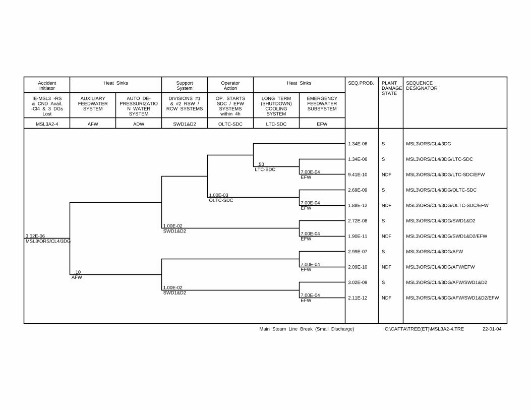
3.02E-06MSL3\ORS/CL4/3DG
.10AFW
1.00E-02SWD1&D2
1.00E-02SWD1&D2
1.00E-03OLTC-SDC
.50LTC-SDC 7.00E-04
EFW
7.00E-04EFW
7.00E-04EFW
7.00E-04EFW
7.00E-04EFW
SEQ.PROB. PLANTDAMAGESTATE
SEQUENCEDESIGNATOR
1.34E-06 S MSL3\ORS/CL4/3DG
1.34E-06 S MSL3\ORS/CL4/3DG/LTC-SDC
9.41E-10 NDF MSL3\ORS/CL4/3DG/LTC-SDC/EFW
2.69E-09 S MSL3\ORS/CL4/3DG/OLTC-SDC
1.88E-12 NDF MSL3\ORS/CL4/3DG/OLTC-SDC/EFW
2.72E-08 S MSL3\ORS/CL4/3DG/SWD1&D2
1.90E-11 NDF MSL3\ORS/CL4/3DG/SWD1&D2/EFW
2.99E-07 S MSL3\ORS/CL4/3DG/AFW
2.09E-10 NDF MSL3\ORS/CL4/3DG/AFW/EFW
3.02E-09 S MSL3\ORS/CL4/3DG/AFW/SWD1&D2
2.11E-12 NDF MSL3\ORS/CL4/3DG/AFW/SWD1&D2/EFW
MSL3A2-4
IE-MSL3 -RS& CND Avail.-Cl4 & 3 DGs
Lost
AccidentInitiator
AFW
AUXILIARYFEEDWATER
SYSTEM
ADW
AUTO DE-PRESSURIZATIO
N WATERSYSTEM
Heat Sinks
SWD1&D2
DIVISIONS #1& #2 RSW /
RCW SYSTEMS
SupportSystem
OLTC-SDC
OP. STARTSSDC / EFWSYSTEMSwithin 4h
OperatorAction
LTC-SDC
LONG TERM(SHUTDOWN)
COOLINGSYSTEM
EFW
EMERGENCYFEEDWATERSUBSYSTEM
Heat Sinks
Main Steam Line Break (Small Discharge) C:\CAFTA\TREE(ET)\MSL3A2-4.TRE 22-01-04
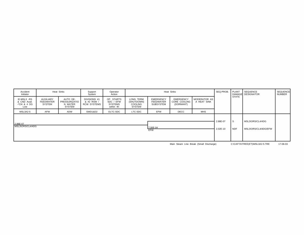
2.88E-07MSL3\ORS/CL4/4DG 7.00E-04
EFW
SEQ.PROB. PLANTDAMAGESTATE
SEQUENCEDESIGNATOR
SEQUENCENUMBER
2.88E-07 S MSL3\ORS/CL4/4DG
2.02E-10 NDF MSL3\ORS/CL4/4DG/EFW
MSL3A2-5
IE-MSL3 -RS& CND Avail.-*Cl4 & 4 DG
Lost
AccidentInitiator
AFW
AUXILIARYFEEDWATER
SYSTEM
ADW
AUTO DE-PRESSURIZATIO
N WATERSYSTEM
Heat Sinks
SWD1&D2
DIVISIONS #1& #2 RSW /
RCW SYSTEMS
SupportSystem
OLTC-SDC
OP. STARTSSDC / EFWSYSTEMSwithin 4h
OperatorAction
LTC-SDC
LONG TERM(SHUTDOWN)
COOLINGSYSTEM
EFW
EMERGENCYFEEDWATERSUBSYSTEM
DECC
EMERGENCYCORE COOLING
(DORMANT)
MHS
MODERATOR ASA HEAT SINK
Heat Sinks
Main Steam Line Break (Small Discharge) C:\CAFTA\TREE(ET)\MSL3A2-5.TRE 17-06-03
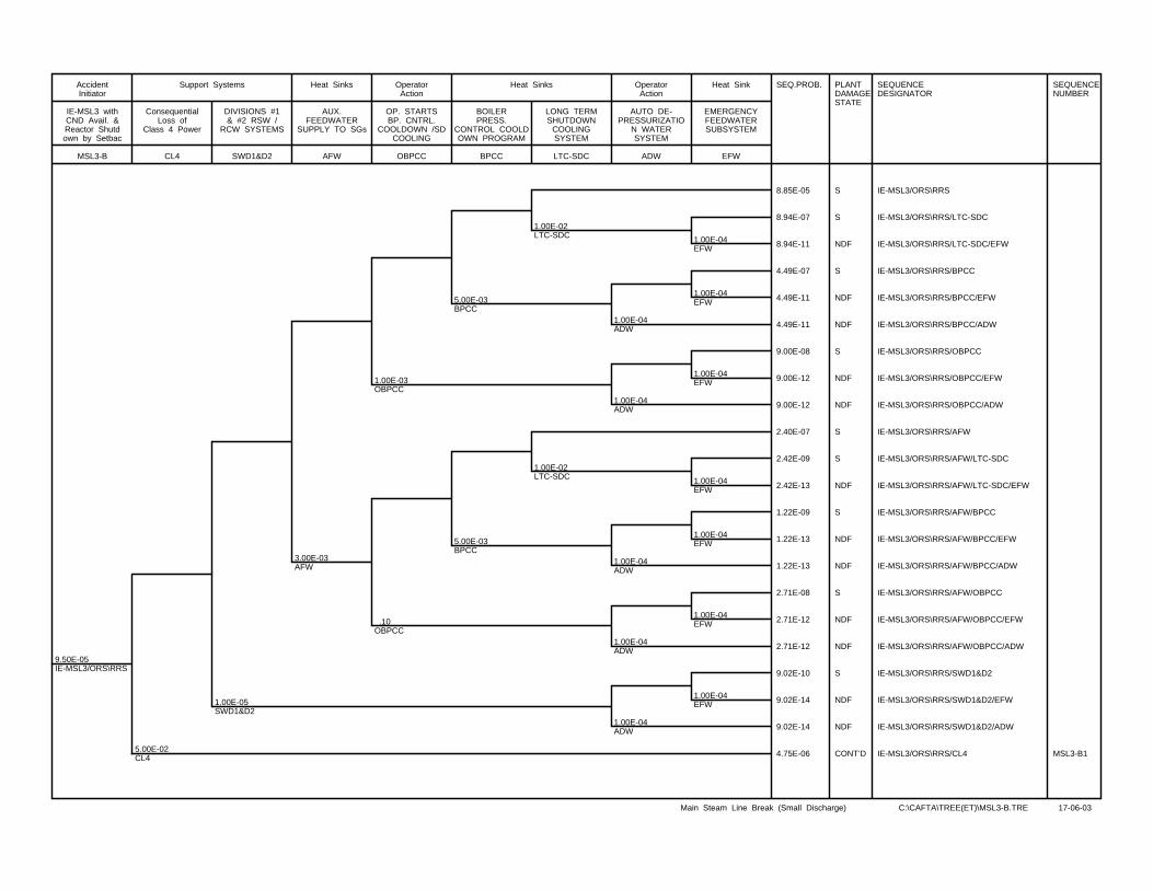
9.50E-05IE-MSL3/ORS\RRS
5.00E-02CL4
1.00E-05SWD1&D2
3.00E-03AFW
1.00E-03OBPCC
.10OBPCC
5.00E-03BPCC
5.00E-03BPCC
1.00E-02LTC-SDC
1.00E-02LTC-SDC
1.00E-04ADW
1.00E-04ADW
1.00E-04ADW
1.00E-04ADW
1.00E-04ADW
1.00E-04EFW
1.00E-04EFW
1.00E-04EFW
1.00E-04EFW
1.00E-04EFW
1.00E-04EFW
1.00E-04EFW
SEQ.PROB. PLANTDAMAGESTATE
SEQUENCEDESIGNATOR
SEQUENCENUMBER
8.85E-05 S IE-MSL3/ORS\RRS
8.94E-07 S IE-MSL3/ORS\RRS/LTC-SDC
8.94E-11 NDF IE-MSL3/ORS\RRS/LTC-SDC/EFW
4.49E-07 S IE-MSL3/ORS\RRS/BPCC
4.49E-11 NDF IE-MSL3/ORS\RRS/BPCC/EFW
4.49E-11 NDF IE-MSL3/ORS\RRS/BPCC/ADW
9.00E-08 S IE-MSL3/ORS\RRS/OBPCC
9.00E-12 NDF IE-MSL3/ORS\RRS/OBPCC/EFW
9.00E-12 NDF IE-MSL3/ORS\RRS/OBPCC/ADW
2.40E-07 S IE-MSL3/ORS\RRS/AFW
2.42E-09 S IE-MSL3/ORS\RRS/AFW/LTC-SDC
2.42E-13 NDF IE-MSL3/ORS\RRS/AFW/LTC-SDC/EFW
1.22E-09 S IE-MSL3/ORS\RRS/AFW/BPCC
1.22E-13 NDF IE-MSL3/ORS\RRS/AFW/BPCC/EFW
1.22E-13 NDF IE-MSL3/ORS\RRS/AFW/BPCC/ADW
2.71E-08 S IE-MSL3/ORS\RRS/AFW/OBPCC
2.71E-12 NDF IE-MSL3/ORS\RRS/AFW/OBPCC/EFW
2.71E-12 NDF IE-MSL3/ORS\RRS/AFW/OBPCC/ADW
9.02E-10 S IE-MSL3/ORS\RRS/SWD1&D2
9.02E-14 NDF IE-MSL3/ORS\RRS/SWD1&D2/EFW
9.02E-14 NDF IE-MSL3/ORS\RRS/SWD1&D2/ADW
4.75E-06 CONT’D IE-MSL3/ORS\RRS/CL4 MSL3-B1
MSL3-B
IE-MSL3 withCND Avail. &Reactor Shutdown by Setbac
AccidentInitiator
CL4
ConsequentialLoss of
Class 4 Power
SWD1&D2
DIVISIONS #1& #2 RSW /
RCW SYSTEMS
Support Systems
AFW
AUX.FEEDWATER
SUPPLY TO SGs
Heat Sinks
OBPCC
OP. STARTSBP. CNTRL.
COOLDOWN /SDCOOLING
OperatorAction
BPCC
BOILERPRESS.
CONTROL COOLDOWN PROGRAM
LTC-SDC
LONG TERMSHUTDOWN
COOLINGSYSTEM
Heat Sinks
ADW
AUTO DE-PRESSURIZATIO
N WATERSYSTEM
OperatorAction
EFW
EMERGENCYFEEDWATERSUBSYSTEM
Heat Sink
Main Steam Line Break (Small Discharge) C:\CAFTA\TREE(ET)\MSL3-B.TRE 17-06-03
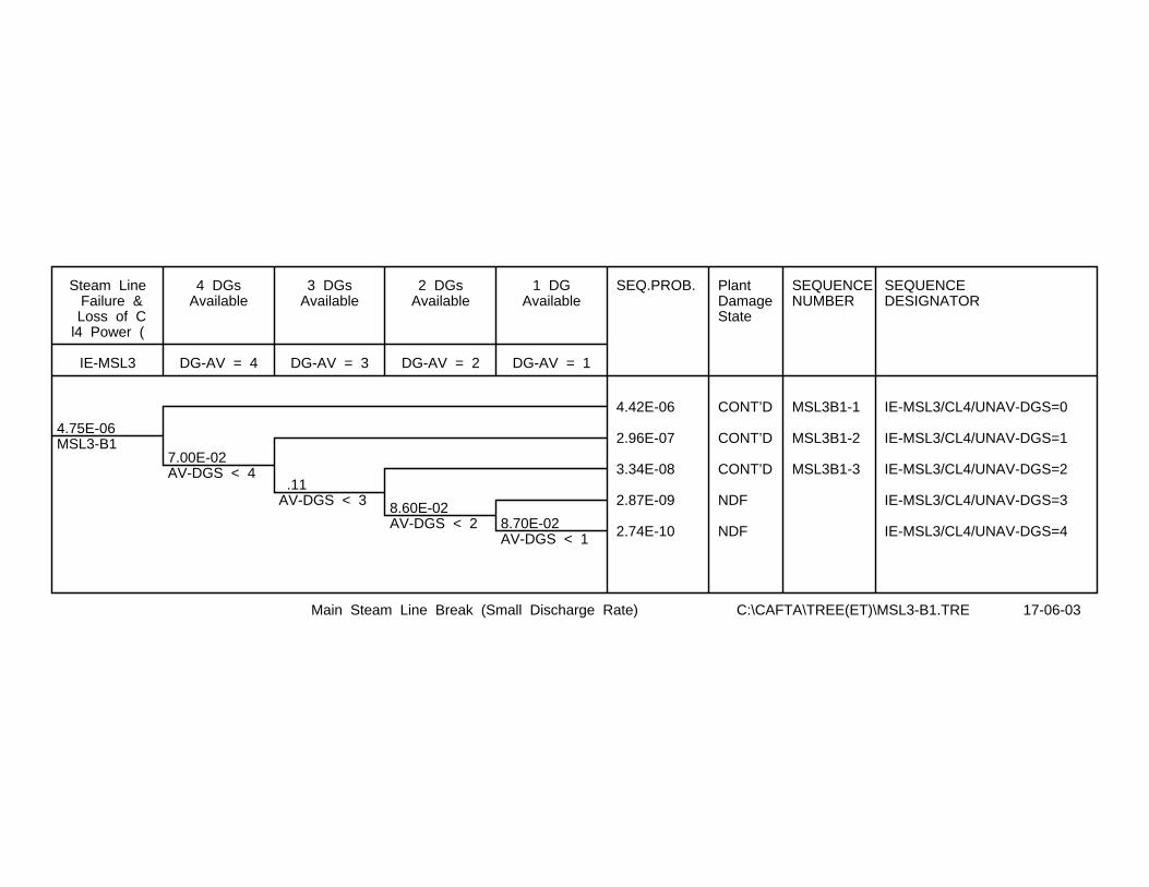
4.75E-06MSL3-B1
7.00E-02AV-DGS < 4
.11AV-DGS < 3 8.60E-02
AV-DGS < 2 8.70E-02AV-DGS < 1
SEQ.PROB. PlantDamageState
SEQUENCENUMBER
SEQUENCEDESIGNATOR
4.42E-06 CONT’D MSL3B1-1 IE-MSL3/CL4/UNAV-DGS=0
2.96E-07 CONT’D MSL3B1-2 IE-MSL3/CL4/UNAV-DGS=1
3.34E-08 CONT’D MSL3B1-3 IE-MSL3/CL4/UNAV-DGS=2
2.87E-09 NDF IE-MSL3/CL4/UNAV-DGS=3
2.74E-10 NDF IE-MSL3/CL4/UNAV-DGS=4
IE-MSL3
Steam Line Failure & Loss of Cl4 Power (
DG-AV = 4
4 DGsAvailable
DG-AV = 3
3 DGsAvailable
DG-AV = 2
2 DGsAvailable
DG-AV = 1
1 DGAvailable
Main Steam Line Break (Small Discharge Rate) C:\CAFTA\TREE(ET)\MSL3-B1.TRE 17-06-03

4.42E-06IE-MSL3/ORS/CL4
1.00E-05SWD1&D2
6.00E-03AFW
1.00E-03OBPCC
5.00E-03BPCC
1.00E-02LTC-SDC
1.00E-04ADW
1.00E-04ADW
1.00E-04ADW
1.00E-04ERFW
7.00E-04EFW
7.00E-04EFW
7.00E-04EFW
7.00E-04EFW
SEQ.PROB. PLANTDAMAGESTATE
SEQUENCEDESIGNATOR
4.32E-06 S IE-MSL3/ORS/CL4
4.36E-08 S IE-MSL3/ORS/CL4/LTC-SDC
3.06E-11 NDF IE-MSL3/ORS/CL4/LTC-SDC/EFW
4.37E-12 NDF IE-MSL3/ORS/CL4/LTC-SDC/ADW
2.19E-08 S IE-MSL3/ORS/CL4/BPCC
1.54E-11 S IE-MSL3/ORS/CL4/BPCC/EFW
2.19E-12 NDF IE-MSL3/ORS/CL4/BPCC/ADW
4.39E-09 S IE-MSL3/ORS/CL4/OBPCC
3.08E-12 NDF IE-MSL3/ORS/CL4/OBPCC/EFW
4.39E-13 NDF IE-MSL3/ORS/CL4/OBPCC/ADW
2.65E-08 S IE-MSL3/ORS/CL4/AFW
1.86E-11 NDF IE-MSL3/ORS/CL4/AFW/EFW
2.65E-12 NDF IE-MSL3/ORS/CL4/AFW/ERFW
4.42E-11 NDF IE-MSL3/ORS/CL4/SWD1&D2
MSL3B1-1
IE-MSL3 withCND Avail &
RS by Setback (CL4 Lost)
AccidentInitiator
SWD1&D2
DIVISIONS #1& #2 RSW /
RCW SYSTEMS
SupportSystems
AFW
AUX.FEEDWATER
SUPPLY TO SGs
Heat Sinks
OBPCC
OP. STARTSSG PRES. CNTRL COOLDOWN &
SDC SYSTEM
OperatorAction
BPCC
BOILERPRESS.
CONTROL COOLDOWN PROGRAM
LTC-SDC
LONG TERM(SHUTDOWN)
COOLINGSYSTEM
ADW
AUTO DE-PRESSURIZATIO
N WATERSYSTEM
EFW
EMERGENCYFEEDWATERSUB-SYSTEM
Heat Sinks
MAIN STEAM LINE BREAK CAUSING DEAERATOR LOW LEVEL C:\CAFTA\TREE(ET)\MSL3B1-1.TRE 17-06-03
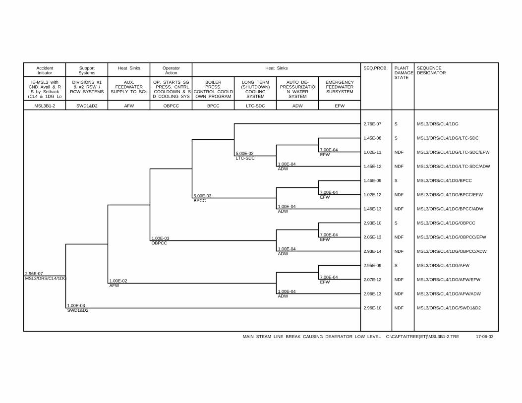
2.96E-07MSL3/ORS/CL4/1DG
1.00E-03SWD1&D2
1.00E-02AFW
1.00E-03OBPCC
5.00E-03BPCC
5.00E-02LTC-SDC
1.00E-04ADW
1.00E-04ADW
1.00E-04ADW
1.00E-04ADW
7.00E-04EFW
7.00E-04EFW
7.00E-04EFW
7.00E-04EFW
SEQ.PROB. PLANTDAMAGESTATE
SEQUENCEDESIGNATOR
2.76E-07 S MSL3/ORS/CL4/1DG
1.45E-08 S MSL3/ORS/CL4/1DG/LTC-SDC
1.02E-11 NDF MSL3/ORS/CL4/1DG/LTC-SDC/EFW
1.45E-12 NDF MSL3/ORS/CL4/1DG/LTC-SDC/ADW
1.46E-09 S MSL3/ORS/CL4/1DG/BPCC
1.02E-12 NDF MSL3/ORS/CL4/1DG/BPCC/EFW
1.46E-13 NDF MSL3/ORS/CL4/1DG/BPCC/ADW
2.93E-10 S MSL3/ORS/CL4/1DG/OBPCC
2.05E-13 NDF MSL3/ORS/CL4/1DG/OBPCC/EFW
2.93E-14 NDF MSL3/ORS/CL4/1DG/OBPCC/ADW
2.95E-09 S MSL3/ORS/CL4/1DG/AFW
2.07E-12 NDF MSL3/ORS/CL4/1DG/AFW/EFW
2.96E-13 NDF MSL3/ORS/CL4/1DG/AFW/ADW
2.96E-10 NDF MSL3/ORS/CL4/1DG/SWD1&D2
MSL3B1-2
IE-MSL3 withCND Avail & RS by Setback
(CL4 & 1DG Lo
AccidentInitiator
SWD1&D2
DIVISIONS #1& #2 RSW /
RCW SYSTEMS
SupportSystems
AFW
AUX.FEEDWATER
SUPPLY TO SGs
Heat Sinks
OBPCC
OP. STARTS SG PRESS. CNTRL
COOLDOWN & SD COOLING SYS
OperatorAction
BPCC
BOILERPRESS.
CONTROL COOLDOWN PROGRAM
LTC-SDC
LONG TERM(SHUTDOWN)
COOLINGSYSTEM
ADW
AUTO DE-PRESSURIZATIO
N WATERSYSTEM
EFW
EMERGENCYFEEDWATERSUBSYSTEM
Heat Sinks
MAIN STEAM LINE BREAK CAUSING DEAERATOR LOW LEVEL C:\CAFTA\TREE(ET)\MSL3B1-2.TRE 17-06-03
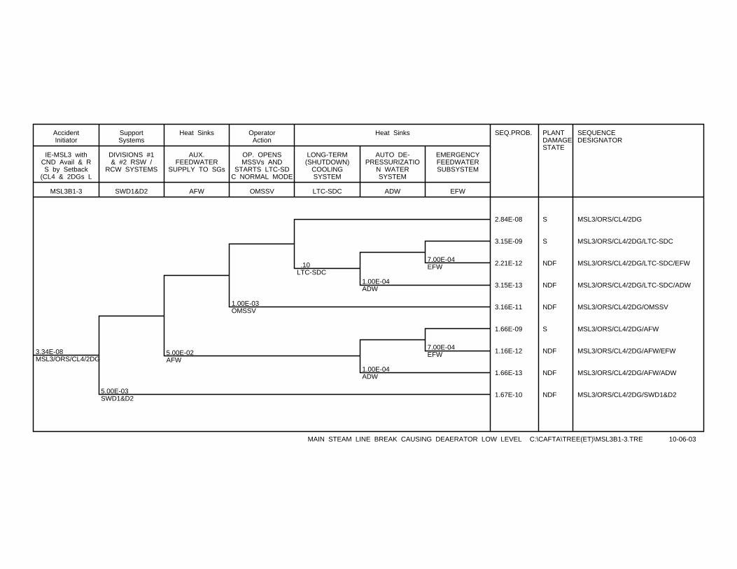
3.34E-08MSL3/ORS/CL4/2DG
5.00E-03SWD1&D2
5.00E-02AFW
1.00E-03OMSSV
.10LTC-SDC
1.00E-04ADW
1.00E-04ADW
7.00E-04EFW
7.00E-04EFW
SEQ.PROB. PLANTDAMAGESTATE
SEQUENCEDESIGNATOR
2.84E-08 S MSL3/ORS/CL4/2DG
3.15E-09 S MSL3/ORS/CL4/2DG/LTC-SDC
2.21E-12 NDF MSL3/ORS/CL4/2DG/LTC-SDC/EFW
3.15E-13 NDF MSL3/ORS/CL4/2DG/LTC-SDC/ADW
3.16E-11 NDF MSL3/ORS/CL4/2DG/OMSSV
1.66E-09 S MSL3/ORS/CL4/2DG/AFW
1.16E-12 NDF MSL3/ORS/CL4/2DG/AFW/EFW
1.66E-13 NDF MSL3/ORS/CL4/2DG/AFW/ADW
1.67E-10 NDF MSL3/ORS/CL4/2DG/SWD1&D2
MSL3B1-3
IE-MSL3 withCND Avail & RS by Setback
(CL4 & 2DGs L
AccidentInitiator
SWD1&D2
DIVISIONS #1& #2 RSW /
RCW SYSTEMS
SupportSystems
AFW
AUX.FEEDWATER
SUPPLY TO SGs
Heat Sinks
OMSSV
OP. OPENSMSSVs AND
STARTS LTC-SDC NORMAL MODE
OperatorAction
LTC-SDC
LONG-TERM(SHUTDOWN)
COOLINGSYSTEM
ADW
AUTO DE-PRESSURIZATIO
N WATERSYSTEM
EFW
EMERGENCYFEEDWATERSUBSYSTEM
Heat Sinks
MAIN STEAM LINE BREAK CAUSING DEAERATOR LOW LEVEL C:\CAFTA\TREE(ET)\MSL3B1-3.TRE 10-06-03

2.50E-07MSL3-C
7.00E-02AV-DGS < 4
.11AV-DGS < 3
8.60E-02AV-DGS < 2 8.70E-02
AV-DGS < 1
SEQ.PROB. PLANTDAMAGESTATE
SEQUENCENUMBER
SEQUENCEDESIGNATOR
2.32E-07 CONT’D MSL3C-1 IE-MSL3/CL4/UNAV-DGS=0
1.56E-08 CONT’D MSL3C-2 IE-MSL3/CL4/UNAV-DGS=1
1.76E-09 NDF IE-MSL3/CL4/UNAV-DGS=2
1.51E-10 NDF IE-MSL3/CL4/UNAV-DGS=3
1.44E-11 NDF IE-MSL3/CL4/UNAV-DGS=4
IE-MSL3
Small Steam Line Break & Lossof CL4 (SD
InitiatingEvent
DG-AV=4
4 DGsAvailablefor 24h
DG-AV=3
3 DGsAvailablefor 24h
DG-AV=2
2 DGsAvailablefor 24h
DG-AV=1
1 DGAvailablefor 24h
Class III Power Supply
SMALL STEAM LINE BREAK (Causing Low Deaerator Lvl) C:\CAFTA\TREE(ET)\MSL3-C.TRE 17-06-03

2.32E-07MSL3/ORS/RRS/CL4
1.00E-05SWD1&D2
1.00E-04ADW
7.00E-04EFW
SEQ.PROB. PLANTDAMAGESTATE
SEQUENCEDESIGNATOR
2.32E-07 S MSL3/ORS/RRS/CL4
1.62E-10 NDF MSL3/ORS/RRS/CL4/EFW
2.32E-11 NDF MSL3/ORS/RRS/CL4/ADW
2.32E-12 NDF MSL3/ORS/RRS/CL4/SWD1&D2
MSL3C-1
IE-MSL3 +Loss of FW Inventory (RS by SDS1/2 & LOCl4)
AccidentInitiator
SWD1&D2
DIVISIONS #1& #2 RSW /
RCW SYSTEMS
SupportSystem
AFW
AUX.FEEDWATER
SUPPLY TO SGs
ADW
AUTO DE-PRESSURISATIO
N WATERSYSTEM
EFW
EmergencyFeedwater
Sub-System
Heat Sinks
MAIN STEAM LINE BREAK (Causing Low Deaerator Lvl.) C:\CAFTA\TREE(ET)\MSL3C-1.TRE 10-06-03
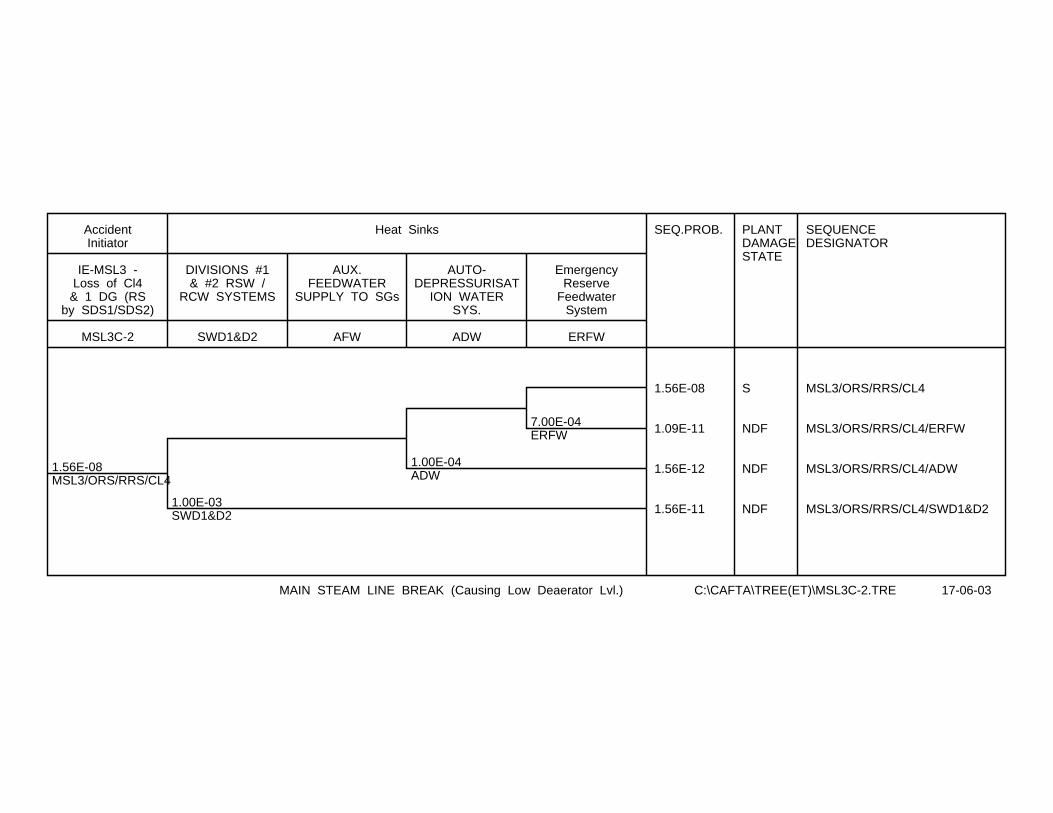
1.56E-08MSL3/ORS/RRS/CL4
1.00E-03SWD1&D2
1.00E-04ADW
7.00E-04ERFW
SEQ.PROB. PLANTDAMAGESTATE
SEQUENCEDESIGNATOR
1.56E-08 S MSL3/ORS/RRS/CL4
1.09E-11 NDF MSL3/ORS/RRS/CL4/ERFW
1.56E-12 NDF MSL3/ORS/RRS/CL4/ADW
1.56E-11 NDF MSL3/ORS/RRS/CL4/SWD1&D2
MSL3C-2
IE-MSL3 -Loss of Cl4& 1 DG (RS
by SDS1/SDS2)
AccidentInitiator
SWD1&D2
DIVISIONS #1& #2 RSW /
RCW SYSTEMS
AFW
AUX.FEEDWATER
SUPPLY TO SGs
ADW
AUTO-DEPRESSURISAT
ION WATERSYS.
ERFW
EmergencyReserve
FeedwaterSystem
Heat Sinks
MAIN STEAM LINE BREAK (Causing Low Deaerator Lvl.) C:\CAFTA\TREE(ET)\MSL3C-2.TRE 17-06-03
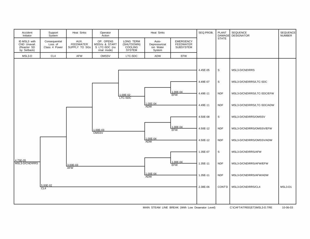
4.75E-05MSL3-D/CND\RRS
5.00E-02CL4
3.00E-03AFW
1.00E-03OMSSV
1.00E-02LTC-SDC
1.00E-04ADW
1.00E-04ADW
1.00E-04ADW
1.00E-04EFW
1.00E-04EFW
1.00E-04EFW
SEQ.PROB. PLANTDAMAGESTATE
SEQUENCEDESIGNATOR
SEQUENCENUMBER
4.45E-05 S MSL3-D/CND\RRS
4.49E-07 S MSL3-D/CND\RRS/LTC-SDC
4.49E-11 NDF MSL3-D/CND\RRS/LTC-SDC/EFW
4.49E-11 NDF MSL3-D/CND\RRS/LTC-SDC/ADW
4.50E-08 S MSL3-D/CND\RRS/OMSSV
4.50E-12 NDF MSL3-D/CND\RRS/OMSSV/EFW
4.50E-12 NDF MSL3-D/CND\RRS/OMSSV/ADW
1.35E-07 S MSL3-D/CND\RRS/AFW
1.35E-11 NDF MSL3-D/CND\RRS/AFW/EFW
1.35E-11 NDF MSL3-D/CND\RRS/AFW/ADW
2.38E-06 CONT’D MSL3-D/CND\RRS/CL4 MSL3-D1
MSL3-D
IE-MSL3 withCND Unavail.(Reactor SDby Setback)
AccidentInitiator
CL4
ConsequentialLoss of
Class 4 Power
SupportSystem
AFW
AUX.FEEDWATER
SUPPLY TO SGs
Heat Sinks
OMSSV
OP. OPENSMSSVs & STARTS LTC-SDC (no
rmal mode)
OperatorAction
LTC-SDC
LONG TERM(SHUTDOWN)
COOLINGSYSTEM
ADW
Auto-Depressurizat
ion WaterSystem
EFW
EMERGENCYFEEDWATERSUBSYSTEM
Heat Sinks
MAIN STEAM LINE BREAK (With Low Deaerator Level) C:\CAFTA\TREE(ET)\MSL3-D.TRE 10-06-03
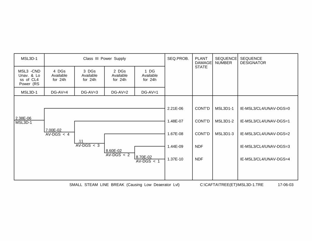
2.38E-06MSL3D-1
7.00E-02AV-DGS < 4
.11AV-DGS < 3
8.60E-02AV-DGS < 2 8.70E-02
AV-DGS < 1
SEQ.PROB. PLANTDAMAGESTATE
SEQUENCENUMBER
SEQUENCEDESIGNATOR
2.21E-06 CONT’D MSL3D1-1 IE-MSL3/CL4/UNAV-DGS=0
1.48E-07 CONT’D MSL3D1-2 IE-MSL3/CL4/UNAV-DGS=1
1.67E-08 CONT’D MSL3D1-3 IE-MSL3/CL4/UNAV-DGS=2
1.44E-09 NDF IE-MSL3/CL4/UNAV-DGS=3
1.37E-10 NDF IE-MSL3/CL4/UNAV-DGS=4
MSL3D-1
MSL3 -CNDUnav. & Loss of CL4Power (RS
MSL3D-1
DG-AV=4
4 DGsAvailablefor 24h
DG-AV=3
3 DGsAvailablefor 24h
DG-AV=2
2 DGsAvailablefor 24h
DG-AV=1
1 DGAvailablefor 24h
Class III Power Supply
SMALL STEAM LINE BREAK (Causing Low Deaerator Lvl) C:\CAFTA\TREE(ET)\MSL3D-1.TRE 17-06-03
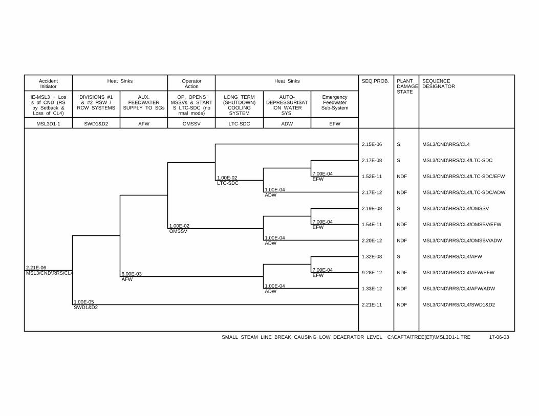
2.21E-06MSL3/CND\RRS/CL4
1.00E-05SWD1&D2
6.00E-03AFW
1.00E-02OMSSV
1.00E-02LTC-SDC
1.00E-04ADW
1.00E-04ADW
1.00E-04ADW
7.00E-04EFW
7.00E-04EFW
7.00E-04EFW
SEQ.PROB. PLANTDAMAGESTATE
SEQUENCEDESIGNATOR
2.15E-06 S MSL3/CND\RRS/CL4
2.17E-08 S MSL3/CND\RRS/CL4/LTC-SDC
1.52E-11 NDF MSL3/CND\RRS/CL4/LTC-SDC/EFW
2.17E-12 NDF MSL3/CND\RRS/CL4/LTC-SDC/ADW
2.19E-08 S MSL3/CND\RRS/CL4/OMSSV
1.54E-11 NDF MSL3/CND\RRS/CL4/OMSSV/EFW
2.20E-12 NDF MSL3/CND\RRS/CL4/OMSSV/ADW
1.32E-08 S MSL3/CND\RRS/CL4/AFW
9.28E-12 NDF MSL3/CND\RRS/CL4/AFW/EFW
1.33E-12 NDF MSL3/CND\RRS/CL4/AFW/ADW
2.21E-11 NDF MSL3/CND\RRS/CL4/SWD1&D2
MSL3D1-1
IE-MSL3 + Loss of CND (RSby Setback &Loss of CL4)
AccidentInitiator
SWD1&D2
DIVISIONS #1& #2 RSW /
RCW SYSTEMS
AFW
AUX.FEEDWATER
SUPPLY TO SGs
Heat Sinks
OMSSV
OP. OPENSMSSVs & STARTS LTC-SDC (no
rmal mode)
OperatorAction
LTC-SDC
LONG TERM(SHUTDOWN)
COOLINGSYSTEM
ADW
AUTO-DEPRESSURISAT
ION WATERSYS.
EFW
EmergencyFeedwater
Sub-System
Heat Sinks
SMALL STEAM LINE BREAK CAUSING LOW DEAERATOR LEVEL C:\CAFTA\TREE(ET)\MSL3D1-1.TRE 17-06-03
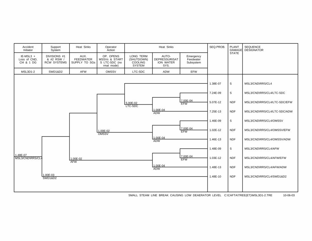
1.48E-07MSL3/CND\RRS/CL4
1.00E-03SWD1&D2
1.00E-02AFW
1.00E-02OMSSV
5.00E-02LTC-SDC
1.00E-04ADW
1.00E-04ADW
1.00E-04ADW
7.00E-04EFW
7.00E-04EFW
7.00E-04EFW
SEQ.PROB. PLANTDAMAGESTATE
SEQUENCEDESIGNATOR
1.38E-07 S MSL3/CND\RRS/CL4
7.24E-09 S MSL3/CND\RRS/CL4/LTC-SDC
5.07E-12 NDF MSL3/CND\RRS/CL4/LTC-SDC/EFW
7.25E-13 NDF MSL3/CND\RRS/CL4/LTC-SDC/ADW
1.46E-09 S MSL3/CND\RRS/CL4/OMSSV
1.02E-12 NDF MSL3/CND\RRS/CL4/OMSSV/EFW
1.46E-13 NDF MSL3/CND\RRS/CL4/OMSSV/ADW
1.48E-09 S MSL3/CND\RRS/CL4/AFW
1.03E-12 NDF MSL3/CND\RRS/CL4/AFW/EFW
1.48E-13 NDF MSL3/CND\RRS/CL4/AFW/ADW
1.48E-10 NDF MSL3/CND\RRS/CL4/SWD1&D2
MSL3D1-2
IE-MSL3 +Loss of CND,Cl4 & 1 DG
AccidentInitiator
SWD1&D2
DIVISIONS #1& #2 RSW /
RCW SYSTEMS
SupportSystem
AFW
AUX.FEEDWATER
SUPPLY TO SGs
Heat Sinks
OMSSV
OP. OPENSMSSVs & STARTS LTC-SDC (no
rmal mode)
OperatorAction
LTC-SDC
LONG TERM(SHUTDOWN)
COOLINGSYSTEM
ADW
AUTO-DEPRESSURISAT
ION WATERSYS.
EFW
EmergencyFeedwaterSubsystem
Heat Sinks
SMALL STEAM LINE BREAK CAUSING LOW DEAERATOR LEVEL C:\CAFTA\TREE(ET)\MSL3D1-2.TRE 10-06-03
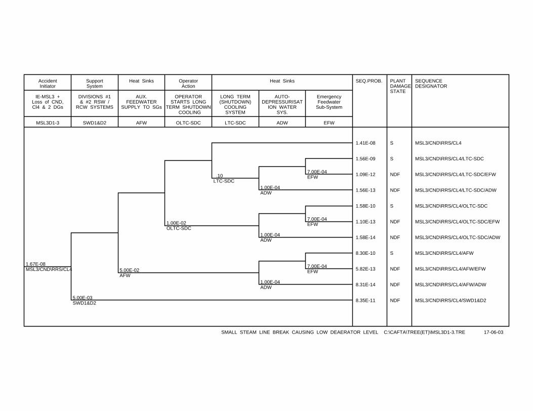
1.67E-08MSL3/CND\RRS/CL4
5.00E-03SWD1&D2
5.00E-02AFW
1.00E-02OLTC-SDC
.10LTC-SDC
1.00E-04ADW
1.00E-04ADW
1.00E-04ADW
7.00E-04EFW
7.00E-04EFW
7.00E-04EFW
SEQ.PROB. PLANTDAMAGESTATE
SEQUENCEDESIGNATOR
1.41E-08 S MSL3/CND\RRS/CL4
1.56E-09 S MSL3/CND\RRS/CL4/LTC-SDC
1.09E-12 NDF MSL3/CND\RRS/CL4/LTC-SDC/EFW
1.56E-13 NDF MSL3/CND\RRS/CL4/LTC-SDC/ADW
1.58E-10 S MSL3/CND\RRS/CL4/OLTC-SDC
1.10E-13 NDF MSL3/CND\RRS/CL4/OLTC-SDC/EFW
1.58E-14 NDF MSL3/CND\RRS/CL4/OLTC-SDC/ADW
8.30E-10 S MSL3/CND\RRS/CL4/AFW
5.82E-13 NDF MSL3/CND\RRS/CL4/AFW/EFW
8.31E-14 NDF MSL3/CND\RRS/CL4/AFW/ADW
8.35E-11 NDF MSL3/CND\RRS/CL4/SWD1&D2
MSL3D1-3
IE-MSL3 +Loss of CND,Cl4 & 2 DGs
AccidentInitiator
SWD1&D2
DIVISIONS #1& #2 RSW /
RCW SYSTEMS
SupportSystem
AFW
AUX.FEEDWATER
SUPPLY TO SGs
Heat Sinks
OLTC-SDC
OPERATORSTARTS LONG
TERM SHUTDOWN COOLING
OperatorAction
LTC-SDC
LONG TERM(SHUTDOWN)
COOLINGSYSTEM
ADW
AUTO-DEPRESSURISAT
ION WATERSYS.
EFW
EmergencyFeedwater
Sub-System
Heat Sinks
SMALL STEAM LINE BREAK CAUSING LOW DEAERATOR LEVEL C:\CAFTA\TREE(ET)\MSL3D1-3.TRE 17-06-03
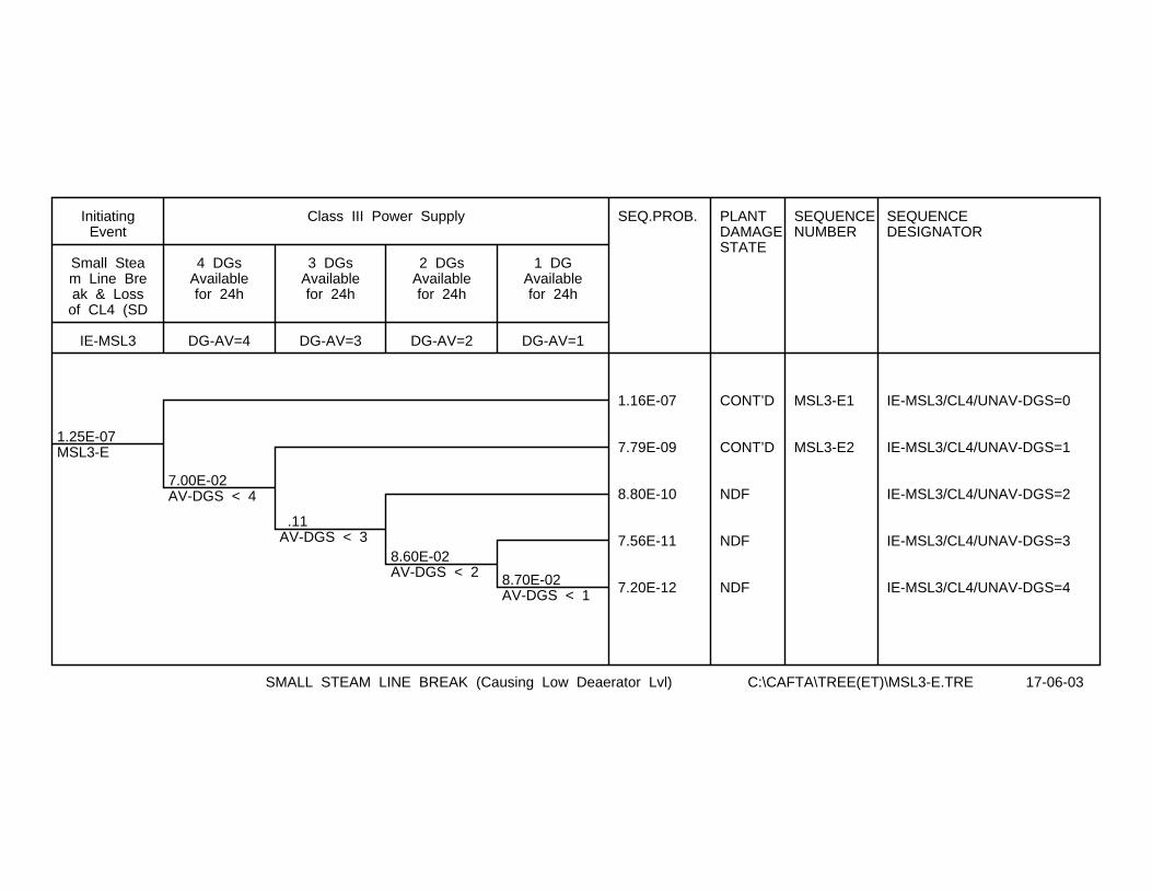
1.25E-07MSL3-E
7.00E-02AV-DGS < 4
.11AV-DGS < 3
8.60E-02AV-DGS < 2 8.70E-02
AV-DGS < 1
SEQ.PROB. PLANTDAMAGESTATE
SEQUENCENUMBER
SEQUENCEDESIGNATOR
1.16E-07 CONT’D MSL3-E1 IE-MSL3/CL4/UNAV-DGS=0
7.79E-09 CONT’D MSL3-E2 IE-MSL3/CL4/UNAV-DGS=1
8.80E-10 NDF IE-MSL3/CL4/UNAV-DGS=2
7.56E-11 NDF IE-MSL3/CL4/UNAV-DGS=3
7.20E-12 NDF IE-MSL3/CL4/UNAV-DGS=4
IE-MSL3
Small Steam Line Break & Lossof CL4 (SD
InitiatingEvent
DG-AV=4
4 DGsAvailablefor 24h
DG-AV=3
3 DGsAvailablefor 24h
DG-AV=2
2 DGsAvailablefor 24h
DG-AV=1
1 DGAvailablefor 24h
Class III Power Supply
SMALL STEAM LINE BREAK (Causing Low Deaerator Lvl) C:\CAFTA\TREE(ET)\MSL3-E.TRE 17-06-03
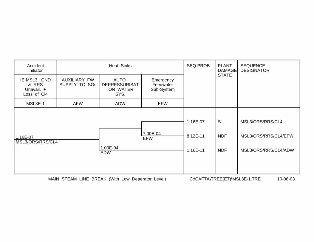
1.16E-07MSL3/ORS/RRS/CL4
1.00E-04ADW
7.00E-04EFW
SEQ.PROB. PLANTDAMAGESTATE
SEQUENCEDESIGNATOR
1.16E-07 S MSL3/ORS/RRS/CL4
8.12E-11 NDF MSL3/ORS/RRS/CL4/EFW
1.16E-11 NDF MSL3/ORS/RRS/CL4/ADW
MSL3E-1
IE-MSL3 -CND& RRS
Unavail. +Loss of Cl4
AccidentInitiator
AFW
AUXILIARY FWSUPPLY TO SGs
ADW
AUTO-DEPRESSURISAT
ION WATERSYS.
EFW
EmergencyFeedwater
Sub-System
Heat Sinks
MAIN STEAM LINE BREAK (With Low Deaerator Level) C:\CAFTA\TREE(ET)\MSL3E-1.TRE 10-06-03

7.79E-09MSL3/CND/RRS/CL4
1.00E-04ADW
7.00E-04EFW
SEQ.PROB. PLANTDAMAGESTATE
SEQUENCEDESIGNATOR
7.78E-09 S MSL3/CND/RRS/CL4
5.45E-12 NDF MSL3/CND/RRS/CL4/EFW
7.79E-13 NDF MSL3/CND/RRS/CL4/ADW
MSL3E-2
IE-MSL3 -CNDUnavail., Los
s of Cl4 & 1DG (RS by SDS1
AccidentInitiator
AFW
AUXILIARY FWSUPPLY TO SGs
ADW
AUTO-DEPRESSURISAT
ION WATERSYS.
EFW
EmergencyFeedwater
Sub-System
Heat Sinks
MAIN STEAM LINE BREAK (With Low Deaerator Level) C:\CAFTA\TREE(ET)\MSL3E-2.TRE 10-06-03
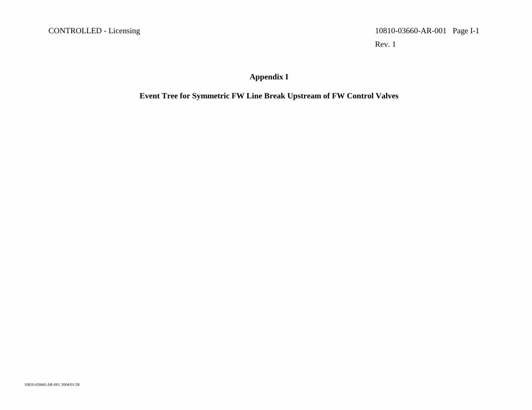
CONTROLLED - Licensing 10810-03660-AR-001 Page I-1
Rev. 1
10810-03660-AR-001 2004/01/28
Appendix I
Event Tree for Symmetric FW Line Break Upstream of FW Control Valves

2.20E-03IE-FWBS
1.00E-06RS
7.00E-02AV-DGS < 4
.11AV-DGS < 3 8.60E-02
AV-DGS < 2 8.70E-02AV-DGS < 1
SEQ.PROB. PlantDamageState
SEQUENCENUMBER
SEQUENCEDESIGNATOR
2.05E-03 CONT’D FWBS-A FWBS/UNAV-DGS=0
1.37E-04 CONT’D FWBS-B FWBS/UNAV-DGS=1
1.55E-05 CONT’D FWBS-C FWBS/UNAV-DGS=2
1.33E-06 CONT’D FWBS-D FWBS/UNAV-DGS=3
1.27E-07 CONT’D FWBS-E FWBS/UNAV-DGS=4
2.20E-09 PDS0 FWBS1
IE-FWBS
Sym. FWLBin TB (upstr. FW reg. valves)
RS
ReactorShutdown
viaSDS1&SDS2
DG-AV = 4
4 DGsAvailablefor 24h
DG-AV = 3
3 DGsAvailablefor 24h
DG-AV = 2
2 DGsAvailablefor 24h
DG-AV = 1
1 DG isAvailablefor 24h
Sym. FWLB in TB C:\CAFTA\TREE(ET)\FWBS-1.TRE 22-01-04

2.05E-03FWBS-A
1.00E-05SWD1&D2
1.00E-04ADW
1.00E-04ADW
7.00E-04EFW
7.00E-04EFW
.10OLTC-SDC
1.00E-02LTC-SDC
SEQ.PROB. CLASS SEQUENCEDESIGNATOR
SEQUENCENUMBER
2.05E-03 S FWBS-A
1.28E-06 S FWBS-A/EFW
1.29E-08 PDS6 FWBS-A/EFW/LTC-SDC FWBS-A1
1.43E-07 PDS6 FWBS-A/EFW/OLTC-SDC FWBS-A2
2.05E-07 PDS6 FWBS-A/ADW FWBS-A3
2.05E-08 S FWBS-A/SWD1&D2
1.43E-11 NDF FWBS-A/SWD1&D2/EFW
2.05E-12 NDF FWBS-A/SWD1&D2/ADW
IE-FWBS
IE-FWBS/CLIV, all fo
ur CLIII DGs av.
Transfer
SWD1&D2
Division1&2 SW
(RSW/RCW)System
SupportSystem
ADW
Auto-Depressurization Water System
EFW
EmergencyFeedwaterSubsystemSupply to
OLTC-SDC
OperatorStarts
LTC-SDC
LTC-SDC
Long TermCoolingSystem
Heat Sink
FWLB SYM. (upstrm. of FW reg. valves) T/B - P2 C:\CAFTA\TREE(ET)\FWBS-2.TRE 22-01-04
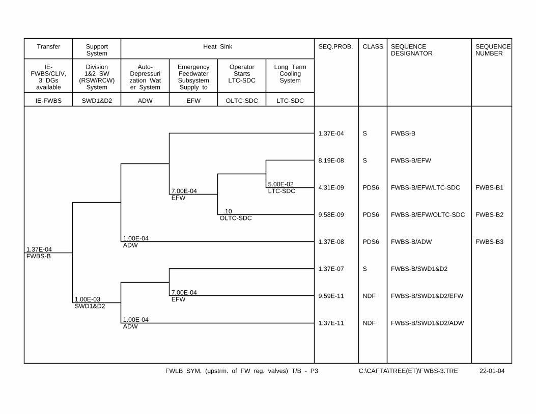
1.37E-04FWBS-B
1.00E-03SWD1&D2
1.00E-04ADW
1.00E-04ADW
7.00E-04EFW
7.00E-04EFW
.10OLTC-SDC
5.00E-02LTC-SDC
SEQ.PROB. CLASS SEQUENCEDESIGNATOR
SEQUENCENUMBER
1.37E-04 S FWBS-B
8.19E-08 S FWBS-B/EFW
4.31E-09 PDS6 FWBS-B/EFW/LTC-SDC FWBS-B1
9.58E-09 PDS6 FWBS-B/EFW/OLTC-SDC FWBS-B2
1.37E-08 PDS6 FWBS-B/ADW FWBS-B3
1.37E-07 S FWBS-B/SWD1&D2
9.59E-11 NDF FWBS-B/SWD1&D2/EFW
1.37E-11 NDF FWBS-B/SWD1&D2/ADW
IE-FWBS
IE-FWBS/CLIV,
3 DGsavailable
Transfer
SWD1&D2
Division1&2 SW
(RSW/RCW)System
SupportSystem
ADW
Auto-Depressurization Water System
EFW
EmergencyFeedwaterSubsystemSupply to
OLTC-SDC
OperatorStarts
LTC-SDC
LTC-SDC
Long TermCoolingSystem
Heat Sink
FWLB SYM. (upstrm. of FW reg. valves) T/B - P3 C:\CAFTA\TREE(ET)\FWBS-3.TRE 22-01-04

1.55E-05FWBS-C
5.00E-03SWD1&D2
1.00E-04ADW
1.00E-04ADW
7.00E-04EFW
7.00E-04EFW
.10OLTC-SDC
.10LTC-SDC
SEQ.PROB. CLASS SEQUENCEDESIGNATOR
SEQUENCENUMBER
1.54E-05 S FWBS-C
8.74E-09 S FWBS-C/EFW
9.72E-10 NDF FWBS-C/EFW/LTC-SDC
1.08E-09 PDS6 FWBS-C/EFW/OLTC-SDC FWBS-C1
1.54E-09 PDS6 FWBS-C/ADW FWBS-C2
7.74E-08 S FWBS-C/SWD1&D2
5.42E-11 NDF FWBS-C/SWD1&D2/EFW
7.75E-12 NDF FWBS-C/SWD1&D2/ADW
IE-FWBS
IE-FWBS/CLIV,
2 DGsavailable
Transfer
SWD1&D2
Division1&2 SW
(RSW/RCW)System
SupportSystem
ADW
Auto-Depressurization Water System
EFW
EmergencyFeedwaterSubsystemSupply to
OLTC-SDC
OperatorStarts
LTC-SDC
LTC-SDC
Long TermCoolingSystem
Heat Sink
FWLB SYM. (upstrm. of FW reg. valves) T/B - P4 C:\CAFTA\TREE(ET)\FWBS-4.TRE 28-01-04
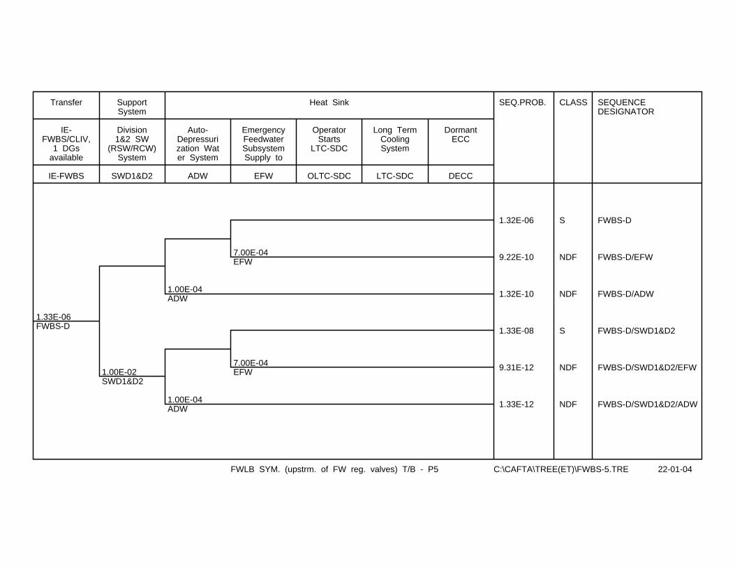
1.33E-06FWBS-D
1.00E-02SWD1&D2
1.00E-04ADW
1.00E-04ADW
7.00E-04EFW
7.00E-04EFW
SEQ.PROB. CLASS SEQUENCEDESIGNATOR
1.32E-06 S FWBS-D
9.22E-10 NDF FWBS-D/EFW
1.32E-10 NDF FWBS-D/ADW
1.33E-08 S FWBS-D/SWD1&D2
9.31E-12 NDF FWBS-D/SWD1&D2/EFW
1.33E-12 NDF FWBS-D/SWD1&D2/ADW
IE-FWBS
IE-FWBS/CLIV,
1 DGsavailable
Transfer
SWD1&D2
Division1&2 SW
(RSW/RCW)System
SupportSystem
ADW
Auto-Depressurization Water System
EFW
EmergencyFeedwaterSubsystemSupply to
OLTC-SDC
OperatorStarts
LTC-SDC
LTC-SDC
Long TermCoolingSystem
DECC
DormantECC
Heat Sink
FWLB SYM. (upstrm. of FW reg. valves) T/B - P5 C:\CAFTA\TREE(ET)\FWBS-5.TRE 22-01-04
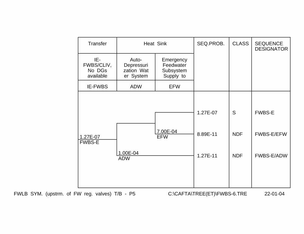
1.27E-07FWBS-E
1.00E-04ADW
7.00E-04EFW
SEQ.PROB. CLASS SEQUENCEDESIGNATOR
1.27E-07 S FWBS-E
8.89E-11 NDF FWBS-E/EFW
1.27E-11 NDF FWBS-E/ADW
IE-FWBS
IE-FWBS/CLIV,
No DGsavailable
Transfer
ADW
Auto-Depressurization Water System
EFW
EmergencyFeedwaterSubsystemSupply to
Heat Sink
FWLB SYM. (upstrm. of FW reg. valves) T/B - P5 C:\CAFTA\TREE(ET)\FWBS-6.TRE 22-01-04

CONTROLLED - Licensing 10810-03660-AR-001 Page J-1
Rev. 1
10810-03660-AR-001 2004/01/28
Appendix J
Event Tree for Asymmetric FW Line Break Downstream of SG Check Valve
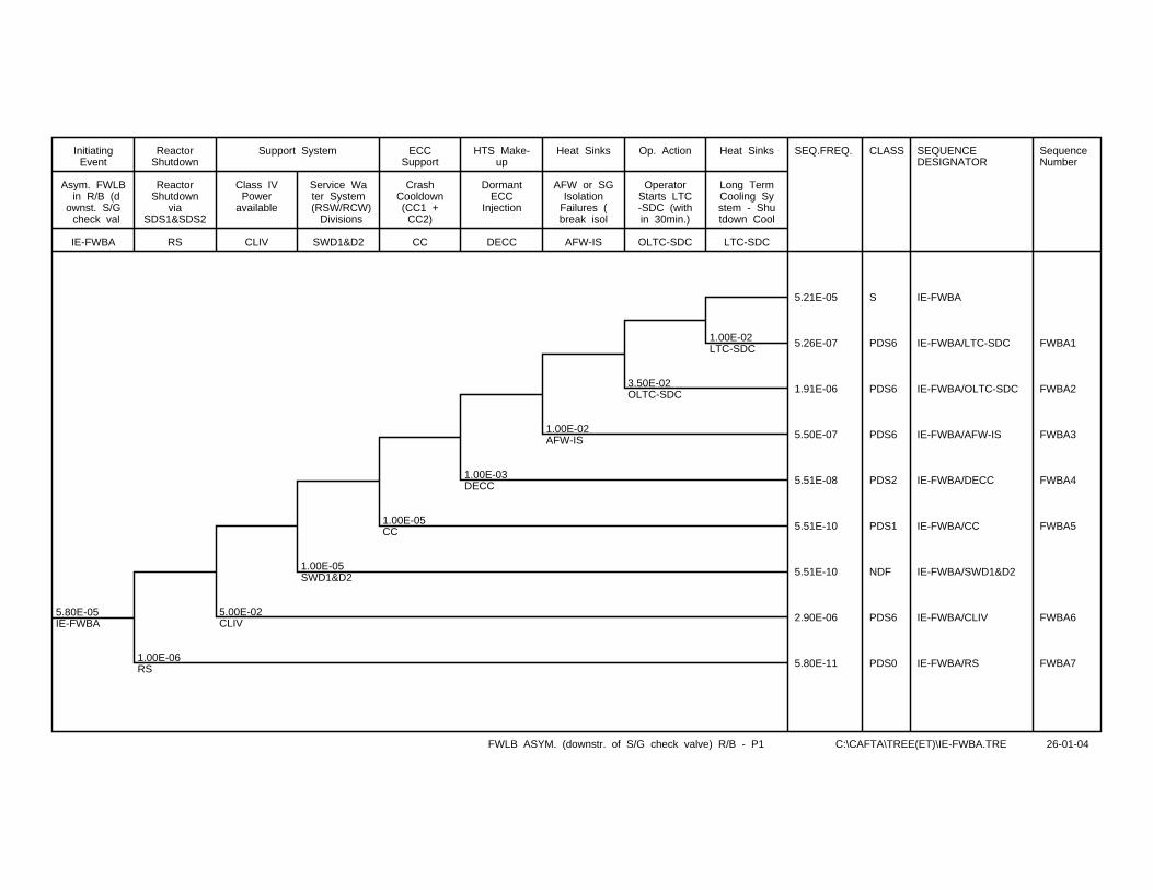
5.80E-05IE-FWBA
1.00E-06RS
5.00E-02CLIV
1.00E-05SWD1&D2
1.00E-05CC
1.00E-03DECC
1.00E-02AFW-IS
3.50E-02OLTC-SDC
1.00E-02LTC-SDC
SEQ.FREQ. CLASS SEQUENCEDESIGNATOR
SequenceNumber
5.21E-05 S IE-FWBA
5.26E-07 PDS6 IE-FWBA/LTC-SDC FWBA1
1.91E-06 PDS6 IE-FWBA/OLTC-SDC FWBA2
5.50E-07 PDS6 IE-FWBA/AFW-IS FWBA3
5.51E-08 PDS2 IE-FWBA/DECC FWBA4
5.51E-10 PDS1 IE-FWBA/CC FWBA5
5.51E-10 NDF IE-FWBA/SWD1&D2
2.90E-06 PDS6 IE-FWBA/CLIV FWBA6
5.80E-11 PDS0 IE-FWBA/RS FWBA7
IE-FWBA
Asym. FWLB in R/B (downst. S/G check val
InitiatingEvent
RS
ReactorShutdown
viaSDS1&SDS2
ReactorShutdown
CLIV
Class IVPower
available
SWD1&D2
Service Water System
(RSW/RCW) Divisions
Support System
CC
CrashCooldown(CC1 +
CC2)
ECCSupport
DECC
DormantECC
Injection
HTS Make-up
AFW-IS
AFW or SGIsolation
Failures (break isol
Heat Sinks
OLTC-SDC
OperatorStarts LTC-SDC (within 30min.)
Op. Action
LTC-SDC
Long TermCooling System - Shutdown Cool
Heat Sinks
FWLB ASYM. (downstr. of S/G check valve) R/B - P1 C:\CAFTA\TREE(ET)\IE-FWBA.TRE 26-01-04

CONTROLLED - Licensing 10810-03660-AR-001 Page K-1
Rev. 1
10810-03660-AR-001 2004/01/28
Appendix K
Event Tree for Loss of Reactivity Control Leading to Core Power Excursion

4.24E-02IE-LOR
1.00E-03SDS1 1.00E-03
SDS2
SEQ.PROB. PLANTDAMAGESTATE
SEQUENCEDESIGNATOR
SEQUENCENUMBER
4.24E-02 S IE-LOR
4.24E-05 S IE-LOR/SDS1
4.24E-08 PDS0 IE-LOR/SDS1/SDS2 LOR1
IE-LOR
LOSS OFREACTIVITYCONTROL
InitiatingEvent
SDS1
SHUT DOWN BYSDS1 ON ROP
OR HLR
SDS2
SHUTDOWN BYSDS2 ON ROP
OR HLR
Reactor Shutdown
LOSS OF REACTIVITY CONTROL CAUSING POWER EXCURSION C:\CAFTA\TREE(ET)\ACR-LOR.TRE 21-07-03