revised submission to ieee transactions on signal ... · revised submission to ieee transactions on...
TRANSCRIPT

REVISED SUBMISSION TO IEEE TRANSACTIONS ON SIGNAL PROCESSING 1
DVB-T Passive Radar Signal ProcessingJames E. Palmer, Member, IEEE, H. Andrew Harms, Student Member, IEEE, Stephen J. Searle,
and Linda M. Davis, Senior Member, IEEE
Abstract
This paper provides a detailed overview of the Digital Video Broadcasting Terrestrial (DVB-T)
signal structure and the implications for passive radar systems that use these signals as illuminators of
opportunity. In particular, we analyze the ambiguity function and explain its delay and Doppler properties
in terms of the underlying structure of the DVB-T signal. Of particular concern for radar range-Doppler
processing are ambiguities consistent in range and Doppler with targets of interest. In this paper we adopt
a mismatched filtering approach for range-Doppler processing. We also recognize that while the structure
of the DVB-T signal introduces ambiguities, the structure can also be exploited to better estimate the
transmitted signal and channel, as well as any mismatch between transmitter and receiver (e.g., clock
offsets). This study presents a scheme for pre-processing both the reference and surveillance signals
obtained by the passive radar to mitigate the effects of the ambiguities and the clutter in range-Doppler
processing. The effectiveness of our proposed scheme in enhancing target detection is demonstrated using
real-world data from an (Australian) 8k-mode DVB-T system. A 29 dB reduction in residual ambiguity
levels over existing techniques is observed, and a 36 dB reduction over standard matched filtering; with
only a 1 dB reduction in the zero-delay, zero-Doppler peak.
Index Terms
passive radar, DVB-T, mismatched filtering, cross-correlation, ambiguity function, passive bistatic
radar, passive coherent location
J. E. Palmer is with the Defence Science & Technology Organisation, Australia, (email: [email protected]).
H. A. Harms is a PhD student at Princeton University, USA, (email: [email protected]), and this work is supported in
part by ONR under grant N00173-06-1-G006 and by AFOSR under grant FA9550-05-1-0443.
L. M. Davis is with the Institute for Telecommunications Research at the University of South Australia, (email:
S. J. Searle is with the Defence Science Institute of the University of Melbourne, Australia (email: [email protected]).
Manuscript in preparation, October 29, 2012.

REVISED SUBMISSION TO IEEE TRANSACTIONS ON SIGNAL PROCESSING 2
EDICS: SAM-RADR
I. INTRODUCTION
Passive radars exploit readily available, non-cooperative sources of radio energy as illuminators of
opportunity to measure reflections from the environment and targets of interest. Without the need for the
deployment and operation of a dedicated transmitter, passive radar systems are significantly less expensive
to implement and operate than their conventional counterparts. A key advantage is that with a suitable
illuminator available, covert surveillance of an area of interest is possible. Another advantage is derived
from the geometry of the passive radar system because it is bistatic. The bistatic radar cross-section (RCS)
of a target is different from its monostatic RCS, and this may aid target detection and classification [1].
Many broadcast and communication signals have been considered and analyzed as possible passive
radar sources including Digital Audio Broadcast (DAB), Digital Video Broadcast (DVB), FM radio,
cellphone base-stations, and various satellite systems [2], [3], [4], [5], [6], [7], [8], [9]. Terrestrial digital
television transmissions, e.g. DVB-T, provide an especially attractive opportunity for passive radar. Digital
television transmitters offer a powerful, well-defined signal with sufficient bandwidth for reasonable
precision in range and are noise-like, thereby allowing for good, consistent range compression and Doppler
estimation of targets [10].
DVB-T signals employ orthogonal frequency division multiplexing (OFDM), and are designed to
provide for good reception of television data. The signals are constructed based on a standard [11]
which includes the data frame structure, guard intervals, and pilot information that is inserted for use by
a DVB-T receiver in order to achieve synchronization and for channel estimation. The structure of the
DVB-T signal gives rise to peaks in the radar ambiguity function, implemented as a cross-correlation of
reference and target surveillance signals.
Ambiguities in the range-Doppler domain are undesirable for two primary reasons: (1) they directly
mask returns from real targets, and (2) some ambiguities will behave like real targets and could therefore
erroneously be detected and tracked by the radar. As these ambiguities are inherent to the transmitted
signal, and as the transmitted signal structure is beyond the control of the passive radar system designer,
ambiguities must be managed at the receiver. In this paper we will show that one method for mitigating
ambiguities is to modify the LOS reference signal such that it becomes slightly mismatched to the
surveillance signal.
The ambiguity function of DVB-T sources has been studied previously, albeit with a particular emphasis
on the 2k-mode (2048 OFDM subcarriers). Various methods suited to the 2k-mode have been proposed

REVISED SUBMISSION TO IEEE TRANSACTIONS ON SIGNAL PROCESSING 3
that achieve improvement via manipulation or filtering of the reference signal prior to range-Doppler
processing [5], [6], [12]. Their efficacy for 8k-mode (8192 OFDM subcarriers) was not considered, nor
were these techniques validated using real data.
In this paper, we extend the study of the ambiguity function to the 8k-mode DVB-T signals, formalizing
the analysis of the ambiguity function to fully identify and explain the source of the ambiguities. Due
to the increase in the symbol length over the 2k-mode signal, ambiguities caused by pilots within the
symbol (so-called intra-symbol ambiguities) dominate for typical target ranges of interest. As with the
previously proposed methods for the 2k-mode signals, we adopt a mismatched reference approach for
range-Doppler processing of the 8k-mode signals. Since hardware- and software-based demodulators for
DVB-T signals are readily available, we assume that error-free digital data is available for use in our
passive radar processing and that we therefore have direct access to the structure of the reference signal
(as required for the methods of [5], [6]). A key distinction between our approach and [5], [6] is that we
modify our reference signal to create a mismatched signal that attenuates the effect of the pilots in terms
of the cross-correlation output rather than the input. The method of [12] also considers the output of a
mismatched cross-correlation, but assumes that direct access to the structure of the reference signal is
not available and instead achieves their mismatch by filtering the measured reference signal directly.
Carefully crafted demodulation and remodulation of the reference signal are central to our approach.
As such, we consider both the advantages and disadvantages presented by the structure of the DVB-
T signal. While the structure does introduce undesirable ambiguities it can also be exploited to better
estimate the transmitted signal and channel as well as any front-end mismatch, such as carrier offset
between the transmitter and receiver. Based on this, we propose a novel scheme for pre-processing the
reference and surveillance signals obtained by the passive radar system to mitigate the effects of both the
ambiguities and the clutter in range-Doppler processing. In contrast to other works, we apply our scheme
to real-world data from an 8k-mode DVB-T system [2] to demonstrate its effectiveness in enhancing
target detection. Furthermore, we highlight the necessity of the additional signal processing undertaken
to demodulate and remodulate the reference signal in achieving successful ambiguity mitigation. We
observe a 29 dB reduction in residual ambiguity levels over existing mismatched techniques and greater
than 36 dB reduction over standard matched filtering. It should be noted that the focus of this paper is on
mitigating undesirable range-Doppler ambiguities and maximising target signal-to-noise ratio (SNR) and
system dynamic range. As such, subsequent processing such as detection and tracking are not considered
in detail here.

REVISED SUBMISSION TO IEEE TRANSACTIONS ON SIGNAL PROCESSING 4
II. DVB-T SIGNAL OVERVIEW
DVB-T signals have a very specific structure designed to provide for good reception of television
signals as detailed in [11]. A brief summary of the relevant portions influencing a passive radar system
are provided here.
A. OFDM Frame Structure
The DVB-T signal uses OFDM with K = 2048 or K = 8192 subcarriers depending on the operating
mode, hence 2k- or 8k-mode operation. An OFDM symbol has a duration of TS seconds and consists
of KC < K active carriers. Symbols are organized into frames, with each DVB-T frame consisting
of L = 68 OFDM symbols. A super-frame consists of four frames and is used to match the OFDM
signaling with the framing for the error control coding in the system. The OFDM symbols carry three
different types of data: 1) the MPEG-2 video data stream, 2) the DVB-T transmission parameter signal,
and 3) pilots.
1) Video Data: The MPEG-2 stream first passes through a series of stages including bit-randomization,
outer-coding, and inner-coding before being mapped onto the signal constellation. This results in the
information appearing on these carriers as random data and, thus, noise-like. The noise-like nature of
this signal also produces a flat spectrum [13]. The data carriers are modulated with either quadrature
phase shift keying (QPSK), 16-quadrature amplitude modulation (QAM), or 64-QAM depending on the
operating mode as defined in the standard.
2) Transmission Parameter Signal (TPS): The TPS carriers convey information about the parameters
of the transmission scheme. The carrier locations are constant and are defined by the standard. All carriers
convey the same information and use differential binary phase shift keying (BPSK). The initial symbol
is derived from a pseudorandom binary sequence (PRBS).
3) Pilots: The pilot symbols aid the receiver in acquisition, demodulation, and decoding of the received
signal. Two types of pilots are included: scattered pilots and continual pilots. The scattered pilots are
uniformly distributed among the carriers in any given symbol. In contrast, the continual pilot signals
occupy the same carrier from symbol to symbol. The location of all pilot symbol carriers is defined by
the DVB-T standard. Fig. 1 illustrates the pilot spacing for a DVB-T OFDM frame where carriers are
indexed horizontally and symbols are indexed vertically. The pilots are based on a PRBS and are BPSK
modulated at a boosted power level 169 times greater than that used for the data and TPS symbols.

REVISED SUBMISSION TO IEEE TRANSACTIONS ON SIGNAL PROCESSING 5
Fig. 1. Pilot structure in the DVB-T OFDM frame. • = boosted power pilot, ◦ = data.
B. Signal Definition
The baseband structure of the transmitted OFDM signal is given by:
x(t) =∞∑m=0
L−1∑`=0
K−1∑k=0
cm`k·ψm`k(t) (1)
where
ψm`k(t) = ej2π k
TU(t−TG−`TS−mLTS)
wm`(t) (2)
and
• m denotes the OFDM frame number,
• ` denotes the OFDM symbol number,
• k denotes the carrier number,
• cm`k are the complex-valued modulation symbols,
• K is the number of subcarriers, 2048 (2k-mode) or 8192 (8k-mode),
• KC < K is the number of active subcarriers (for inactive carriers, effectively cm`k = 0),
• L is the number of symbols per frame,

REVISED SUBMISSION TO IEEE TRANSACTIONS ON SIGNAL PROCESSING 6
• TU is the duration of the useful part of the symbol, i.e. the part of the symbol excluding the guard
interval, containing data and pilot information,
• TG is the guard interval duration and TG/TU is the guard interval fraction,
• TS = TU + TG is the OFDM symbol duration including the guard interval,
• wm`(t) = w(t − `TS − mLTS) is a rectangular windowing function representing the duration of
symbol.
Additionally we define NU , NG and NS as the number of samples in each of the useful part, guard band,
and total symbol period respectively, when sampled with a given sample period. We also define δm` as
the delay to the start of the useful part of the (m, `)-th symbol,
δm` = TG + TS(`+ Lm) (3)
In this paper, we use the example of the Australian DVB-T standard [14], although our analysis and
proposed scheme is suitable for other DVB-T systems and either the 2k or 8k modes. The relevant
parameters for the Australian standard are listed in Table I. It should be noted that in Australia, the
channel spacing is 7 MHz as compared with the European standard that uses a channel spacing of 8 MHz.
The bandwidth of the OFDM signal is correspondingly reduced by a factor of 7/8 [11], [14]. DVB-T
broadcasts in Australia are licensed on contiguous 7 MHz channels numbered 28 (centered at 529.5 MHz)
through 69 (816.5 MHz), although some channels are still currently used for analog transmission. The
passive radar demonstrator system of [2] uses illuminators of opportunity employing the Australian 8k-
mode DVB-T signal, most typically channel 33 (564.5 MHz) which has a guard interval fraction of
TG/TU = 18 . Another interesting feature of Australia’s implementation of the DVB-T standard is that,
unlike Europe, a multi-frequency network implementation is the norm. This means that (typically) each
broadcast channel at each broadcast site is transmitted on a unique frequency. Whilst single frequency
network implementations do exist in Australia they are relatively rare and have limited overlapping
coverage regions. As such, one of the major challenges faced in the European context, that of transmitter
ambiguity, is typically a non-issue in the Australian environment.
III. PASSIVE RADAR RECEIVED SIGNAL MODEL
Fig. 2 depicts the bistatic passive radar geometry. The DVB-T source transmits the signal x(t). The
passive radar receiver collects both a reference signal r(t) via a line-of-sight (LOS) path direct from
the illuminator, and a surveillance signal s(t) reflected via the target(s) of interest. These signals may
be collected using individual antennas mechanically steered in the appropriate directions (as shown) or,

REVISED SUBMISSION TO IEEE TRANSACTIONS ON SIGNAL PROCESSING 7
TABLE I
RELEVANT PARAMETERS FOR AUSTRALIAN 8K MODE
Description Parameter Value
total subcarriers K 8192
active subcarriers KC 6817
symbols per frame L 68
useful part of symbol TU 1024 µs
guard interval fraction TG/TU14
,18
, 116
, 132
carrier spacing 1/TU 976.6 Hz
bandwidth (KC − 1)/TU 6.65625 MHz
reference
surveillance
target
sourcedirect path
interference
r(t)
s(t)
x(t)
Fig. 2. Passive radar geometry: transmitted signal x(t), received reference signal r(t), received surveillance channel s(t).
alternatively, signals may be collected via electronic steering (i.e. beamforming) using an array. Electronic
steering allows for multiple surveillance directions to be simultaneously considered. Assuming either
physical or electronic steering, we consider range-Doppler processing for a particular azimuth angle for
a target of interest. Thus, we have a two-signal model: reference and surveillance.
The LOS reference signal r(t) includes a direct path (DP) component from the transmitter, possibly
several attenuated copies of the DP at short delay due to static multipath (clutter), and sensor noise
introduced at the receiver. At baseband we have
r(t) = α0(t) ∗ x(t− τ0) +C∑i=1
αi(t) ∗ x(t− τi) + ξr(t) (4)

REVISED SUBMISSION TO IEEE TRANSACTIONS ON SIGNAL PROCESSING 8
where ∗ denotes convolution. The i-th resolvable component has a delay of τi and subscript 0 refers to
the DP. The quantity αi(t) encompasses the gain and phase shift of the i-th component, as well as the
combined effect of transmitter/receiver filtering and any unresolved channel effects. Note, it is assumed
that |α0| � |αi| ∀i. The final term, ξr(t), is the additive white Gaussian noise (AWGN) at the LOS
receiver as well as any diminished target return, which we assume to be negligible.
The surveillance signal s(t) includes the target return(s) in the form of a (number of) delayed, Doppler-
shifted, and attenuated version(s) of the transmitted signal, together with clutter and noise. It may also
include a direct path component from the source, termed direct path interference (DPI). The gain/filter
factor βi in the surveillance channel is related to that of the reference channel αi via:
βi(t, θ) = ζi(θ)αi(t) (5)
where ζi is a complex variable that accounts for the gain difference for i = 0, . . . , C. This assumes a
negligible separation between the two receivers and therefore that the channel and analog filtering effects
are the same for both the reference and surveillance channels. As indicated, the complex gain factors will
differ for different receiver beam patterns and/or steering angles (θ). The surveillance signal can thus be
written as:
s(t) = β0(t) ∗ x(t− τ0) +C∑i=1
βi(t) ∗ x(t− τi) +P∑p=0
β?p(t) ∗ x(t− τ?p) + ξs(t) (6)
where there are p = 0, . . . , P returns from a single target, highlighted by subscript ?, and ξs is the additive
noise on the surveillance channel. We note that s(t) looks very similar to r(t) and is only distinguished
as a second signal here in order to highlight the target returns. In many situations, the strength of the
DPI and close in clutter will be many 10s of dBs (and could potentially be 100 dB or more) higher
than that of the target of interest [15]. This wide dynamic range imposes performance requirements on
the receiver radio frequency (RF) hardware and on the analog-to-digital converters [15]. Whilst dynamic
range considerations are important in passive radar they fall outside the scope of this paper and as such
will not be considered in detail here. Suffice it to say that the real data target detections that are presented
later in the paper should reassure the reader that the appropriate considerations were made in the design
and implementation of the system that was employed for this work.
IV. RADAR AMBIGUITY FUNCTION
The ambiguity function for the transmitted signal x(t) is a 2-D autocorrelation function given by the
following [16]:
χxx(τ, ν) =∫ ∞−∞
x(t)·x∗(t− τ)e−j2πνtdt (7)

REVISED SUBMISSION TO IEEE TRANSACTIONS ON SIGNAL PROCESSING 9
where τ and ν are the delay and Doppler hypotheses respectively.
For the passive radar application, we can extract the delay and Doppler profile of the target return
by cross-correlating the reference signal r(t) with the surveillance signal s(t), hereafter referred to as
matched filtering:
χrs(τ, ν) =∫ ∞−∞
r(t)· s∗(t− τ)e−j2πνtdt. (8)
The target’s true range is derived from the delay hypothesis and the angles of arrival (azimuth and
elevation). From (8), we see that ambiguities in our target processing result from the properties of the
autocorrelation function (7) via the definitions (4) and (6).
In practical systems, the reference and surveillance signals are sampled, and the matched filter is
implemented for a window of data. The size of the window is called the coherent processing interval
(CPI) and determines the Doppler resolution and the processing gain of the system. Direct implementation
of the matched filter according to a discrete version of (8) is computationally expensive. In this paper, we
adopt the method used in [17] which was motivated by a typical two stage pulse-Doppler compression
approach. In this method, the coherent processing interval Tcpi is represented as a series of N contiguous
pulses of length Tc (i.e. Tcpi = NTc). Assuming N is even and the intervals are symmetric about t = 0,
the range-compressed pulse at zero-Doppler for the interval with index i becomes
χrs:i (τ, 0) =∫ Tc
0r (t+ iTc) s∗ (t+ iTc − τ) dt. (9)
From the full set of N range-compressed pulses, the Doppler dimension can then be recovered by applying
a Fourier transform across i as follows:
χ′rs (τ, µ) =N/2−1∑i=−N/2
χrs:i (τ, 0) exp(−j2π
Nµi
)≈ χrs(τ, ν) (10)
where µ is the Fourier frequency (per correlation segment, Tc) estimate of ν.
Similar range-Doppler processing techniques have been previously discussed in the literature (most
notably [4], [8], [9]), but these typically are explicitly tailored to OFDM waveforms and require the
cyclic prefix to be discarded. Whilst processing the signal in this manner can offer some advantage, it
is also a very particular implementation (in the data alignment sense) and involves discarding data. In
contrast, the method proposed above is waveform independent and processes the data as contiguous pulses,
i.e. no discarded data. As a result, the method presented here has more flexibility in implementation and
less SNR loss.

REVISED SUBMISSION TO IEEE TRANSACTIONS ON SIGNAL PROCESSING 10
0 200 400 600 800 1000 1200−70
−60
−50
−40
−30
−20
−10
0
X: 1024Y: −19.06
Delay (microseconds)
Pow
er (d
B) X: 1152Y: −33.29
X: 341.5Y: −26.89
Fig. 3. Delay and Doppler projections of the ambiguity function of the full DVB-T signal in 8k-mode operation with a guard
interval of 18
. The plot is normalized to the main peak at zero-delay and zero-Doppler. The peaks at non-zero delay and Doppler
hamper target detection.
A. Features of the DVB-T Ambiguity Function
We now investigate further the ambiguities inherent in the transmitted DVB-T OFDM signal. To
highlight the features explained by the analysis that follows, we simulated the system at baseband in order
to obtain the discrete time equivalent of the autocorrelation function (7). Processing was implemented
using one super-frame (Tcpi = 4 × 68 × TS = 313.34 ms) of data and the results are shown in Fig. 3,
where the autocorrelation function signal strength has been normalized relative to the zero-delay, zero-
Doppler peak. The guard interval used here is TG/TU = 18 to match that typically used in Australia.
Several ambiguities are seen aside from the large peak at zero-delay and zero-Doppler. To make these
clear, Fig. 4 shows only the portions of the ambiguity function that are greater than −55 dB as blue dots
and further highlights those portions greater than −50 dB with red squares.
Our analysis begins with the original autocorrelation function (7), expanded using (1) and (2) to obtain

REVISED SUBMISSION TO IEEE TRANSACTIONS ON SIGNAL PROCESSING 11
−1500
−1000
−500
0
500
1000
1500
0 200 400 600 800 1000 1200 1400
Delay (microseconds)
Dopple
r (H
z)
Fig. 4. Ambiguity function of the full DVB-T signal in 8k-mode operation with a guard interval of 18
where only portions
greater than −55 dB are included. The peaks greater than −50 dB are indicated with red squares and are a result of the pilot
structure of the DVB-T signal. The peaks greater than −55 dB and less than −50 dB are indicated by blue dots.
the following:
χxx(τ, ν) =∫ ∞−∞
∑m`k,m′`′k′
cm`k c∗m′`′k′
ej2π k
TU(t−TG−`TS−mLTS)
e−j2π k′
TU(t−TG−`′TS−m′LTS−τ)
wm`(t) w`′,m′(t− τ)e−j2πνt dt (11)
=∑
m`k,m′`′k′
cm`k c∗m′`′k′ e−j 2π
TU(k−k′)TG e
−j 2πTU
k′TS(`−`′+(m−m′)L)
e−j2πνTS(`+mL) ej 2πTU
k′τχww
(τ − (`− `′)TS − (m−m′)LTS , ν −
(k − k′)TU
)(12)
where
χww(τ, ν) =∫ ∞−∞
w(t)w∗(t− τ)e−j2πνt dt. (13)
Firstly, we note that due to the design of the windowing function χww(τ, ν) ≈ 0 for |τ | > TS . However,
there is no such bound on the function χww(τ, ν) in the dimension of ν. Next, for data samples with
zero mean and unit variance, E[|cm`k|2] = 1 and E[cm`kc∗m′`′k] = 0 for k′ 6= k, `′ 6= `,m′ 6= m, and

REVISED SUBMISSION TO IEEE TRANSACTIONS ON SIGNAL PROCESSING 12
so the sum over terms corresponding to data with k′ 6= k will approach zero for large K. Similarly, for
`′ 6= `,m′ 6= m the sum over data, including that on the same subcarrier (k′ = k), approaches zero. Of
course, χxx(τ, ν) has a large maximum when m′ = m, `′ = ` and k′ = k, with τ = 0, ν = 0, giving
rise to a standard thumbtack ambiguity function were it not for the pilot signals.
Pilot signals give rise to both intra-symbol (τ < TS) ambiguities, and inter-symbol (τ > TS) ambi-
guities. Pilot signals are boosted in power, and the value of cm`k is constant in k, and specifically for
pilot positions `, k defined by the standard, E[cm`kc∗m′`′k′ ] = 16/9 for k = k′ and E[cm`kc∗m′`′k] = 0
otherwise (k′ 6= k). Thus terms corresponding to continual pilots, or scattered pilots on the same carrier,
will contribute significantly to χxx(τ, ν). We see from (12) that ambiguity peaks caused by pilot signals
will occur when:
k = k′ andk′
TU
(τ − TS
(`− `′ + (m−m′)L
))− νTS(`+mL) = integer, (14)
and the corresponding χww(· , ·) is significant. We emphasize here that the peaks in the ambiguity function
arise because a significant number of pilot carriers satisfy the above conditions.
B. Ambiguities from Continual Pilots
Consider the continual pilots. The particular subcarriers k = k′ are defined by the standard [11] and
are not related to ` or m. According to (14), ambiguities can potentially occur for τ = p TU + z TS
and ν = q 1TS
for integers p, q, and z. However, due to the contribution of χww(· , ·) peaks are only
significant for p = 0, 1 and q = 0. We observe ambiguities at TU = 1024µs and TS = 1152µs in Fig. 3
as expected. Note that a delay of 1024µs corresponds to a target distance of at least 153.6 km. Fig. 3
also clearly shows additional ambiguity peaks at zero-Doppler and these are from the scattered pilots. In
fact the peak at 1024 µs results from contributions from both the continual and scattered pilots as well
as the guard interval as we discuss in the following subsections.
C. Ambiguities from Scattered Pilots
The scattered pilots occur, according to the DVB-T standard, at carrier positions k = 3(` mod 4)+12q
for integer q and 0 ≤ k < K. The contributions to the sum across k in (12) will come from every 12-th
carrier, and are still significant since K/12� 1. Let ` = 4a+ b and `′ = 4a′ + b′ for integers a, a′ and
b, b′ = 0, . . . 3. For k = k′, we have b = b′ and thus k = k′ = 3b+ 12q for integers b, q.
For a peak, (14) is of the form:
(3b+ 12q)TU
(τ − TS(4(a− a′) + (m−m′)L))− ν TS(4a+ b+mL) = integer. (15)

REVISED SUBMISSION TO IEEE TRANSACTIONS ON SIGNAL PROCESSING 13
Noting that L = 68 = 4× 17, we have
(3b+ 12q)TU
(τ − 4TS [(a− a′) + 17(m−m′)])− ν TS(4(a+ 17m) + b) = integer. (16)
We now consider the various solutions of (16). The largest contributions to the sum (12) occur for
solutions that contribute for all a and b (i.e. for all `). We can show that these solutions to (16) are of
the form:
τ = TU
(f
12+g
3
)+ z 4TS , ν =
1TS
(f
4+ h
)(17)
for f = 0, 1, 2, 3, and integers g, h, and z.
For the example case with TG/TU = 18 , our analysis predicts intra-symbol ambiguities resulting from
the scattered pilots at the following (τ, ν) combinations: (85µs, 217 Hz), (85µs,−651 Hz), (171µs, 438 Hz),
(171µs,−438 Hz), (256µs, 651 Hz), (256µs,−217 Hz), (341 µs, 0 Hz), (341 µs,±868 Hz), and so on
extending in the delay-Doppler space. The ambiguities listed can be observed and are highlighted in
Fig. 4. These are the largest peaks. Smaller ambiguities also arise from less frequent solutions to (16).
For example ambiguity peaks from scattered pilots at zero-Doppler and τ = TU12 ,
TU9 ,
TU6 ,
TU4 . and so
on can also be clearly seen in Fig. 3.
Equation (17) also shows that the pattern of ambiguities will be repeated at delays of multiples of
4TS . For 8k-mode DVB-T signals 4TS corresponds to a distance ranging from at least 633 km (for a
guard interval 132 ) to 768 km (for a guard interval of 1
4 ). As this distance is assumed to be outside of
the feasible detection range for a passive radar system, these ambiguities may be ignored. It should be
noted that for a 2k-mode DVB-T signal (TU = 224µs), inter-symbol ambiguity peaks at 4TS occur near
1 ms delay and may therefore be within the feasible range of a passive radar system. These ambiguities,
though important for 2k-mode DVB-T signals, are not considered practically significant for 8k-mode
DVB-T signals.
D. Frame and Super-Frame Ambiguities
Ambiguities arising from frame (68 symbols) and super-frame (4 frames) structure are also expected.
For example, the TPS data will be correlated as well as pilot symbols. However, these correspond to
very large time offsets (even beyond those of the inter-symbol ambiguities) and are therefore assumed
to be outside the feasible operating region of the passive radar and the scope of this paper.
E. Guard Interval Ambiguities
Another occurrence of ambiguity peaks is caused by the guard interval which is a cyclic prefix, i.e. a
repetition of the end of the useful DVB-T symbol inserted before the useful part. Thus the repeated part

REVISED SUBMISSION TO IEEE TRANSACTIONS ON SIGNAL PROCESSING 14
Range (monostatic approx lower bound) km
Dop
pler
(H
z)
0 20 40 60 80 100
−600
−400
−200
0
200
400
600
Fig. 5. CFAR detection history without mismatched cross-correlation. The structure of the pilots causes ambiguities that do
not arise from real targets.
of the symbol is separated by a delay of TU , or 1024µs for the Australian 8k-mode DVB-T signals. The
power of these peaks is dependent on the length of the guard interval. If the guard interval is longer, then
more repeated signal contributes to the correlation. As shown in [13] different guard intervals give rise
to different power peaks in the ambiguity function by a factor of up to 18 dB. These ambiguities occur
at ranges of greater than 153.6 km and may be mitigated by using the approaches suggested in [5], [6].
Alternatively, if the desired system detection range is less than the range of these ambiguities, then no
additional processing is required, and they can simply be ignored.
F. Effect of Ambiguities on Target Detection, Tracking and Classification
When considered in isolation, the ambiguities highlighted in Fig. 3 may, at best, be considered minor
annoyances. This is because they: 1) do not occupy a significant portion of the delay-Doppler domain,
and are therefore unlikely to mask target returns (or would not mask them for very long) and 2) the
static Doppler offsets present in the majority of these ambiguities mean that they will not behave like
true targets. In other words, a target’s range migration rate would not be consistent with its Doppler
offset, and should therefore be disregarded by even a fairly rudimentary tracker. Unfortunately, as real
targets are not all point-like and not all of the ambiguities have Doppler offsets, there will be a number

REVISED SUBMISSION TO IEEE TRANSACTIONS ON SIGNAL PROCESSING 15
of ambiguous target peaks that behave like real targets. With static clutter suppressed (see Section V-A5),
Fig. 5 shows a range-Doppler detection history of several moving targets, including a strong return from
a propeller driven aircraft (going from 5 to 10 km), two helicopters (blade flash extending across all
Doppler at approximately 2 km and the other obvious at 200 to 600 Hz at 10 km) as well as a number
of other aircraft (e.g. −200 Hz and 15 km, 300 Hz and 33 km, etc.). This figure reaffirms the fact that
real targets are not all point-like and may even extend in Doppler in such a way as to have portions of
their return deceive a tracker. It also highlights the fact that such false targets are much more likely to
mask real target returns as they occupy a much greater portion of the available range-Doppler domain.
Situations and targets such as these justify the need for ambiguity mitigation techniques, in contrast to
focusing effort on, for example, increasing the sophistication of the tracker.
V. PROPOSED MISMATCHED CROSS-CORRELATION
Mismatched cross-correlation has successfully been demonstrated to improve simulated detection for
2k-mode DVB-T passive radar systems. However, as will be shown in Section VI, our investigations
based on directly applying these techniques to real-world signals from an Australian 8k-mode DVB-T
system highlight that even greater discrimination is required. In this section, we propose a new scheme
for pre-processing the reference and surveillance signals obtained by the passive radar to mitigate the
effects of both the ambiguities and the clutter in range-Doppler processing. Like the existing methods for
the 2k-mode signals, we adopt a mismatched cross-correlation approach for processing of the 8k-mode
signal. A key distinction between our approach and [5], [6] is that we modify our reference signal to
create a mismatched signal that mitigates the effect of the pilots in terms of the cross-correlation output
rather than the input. The method of [12] also considers the output of a mismatched cross-correlation,
but assumes direct access to the structure of the reference signal is not available and instead achieves the
mismatch by filtering the measured reference signal directly. Also, in contrast to these other methods,
our approach uses carefully crafted demodulation and remodulation of the reference signal (4), allowing
for additional benefits of clutter mitigation and noise attenuation in the reference channel.
Fig. 6 shows the block diagram for our proposed processing scheme. The reference signal is first
demodulated via a standards-based DVB-T demodulator in order to retrieve an error-free replica of the
transmitted data, as well as estimates of the channel and clock offset and a coarse estimate of the phase
offset. This error-free replica is then remodulated as per the DVB-T standard to obtain a reasonably
accurate estimate of the transmitted signal. We compare this remodulated signal with the original raw
reference signal in order to estimate the fine phase offset, i.e. the relative drift that exists between the

REVISED SUBMISSION TO IEEE TRANSACTIONS ON SIGNAL PROCESSING 16
Standards-basedDemod
referencesignal
surveillancesignal
Standards-basedRemod
error-freedigital data
Fine Phase Offset
Estimation
Remodincl. Phase
reference signalfor ambiguity-free
Mismatched FilterRange-Doppler
Processing to target detectionand tracking
includes static multipath (clutter)and dynamic multipath (targets)
matched mismatched
reference signalfor clutter cancellation
SurveillanceClutter
Cancellation
includes clock andcoarse frequency offset, plus
channel equalization parameters
Remod incl. Phase and Pilot
Attenuation
Fig. 6. Proposed pre-processing and mismatched cross-correlation for passive radar detection.
local oscillators of the transmitter and the passive radar receiver. The error-free digital data is then
remodulated in parallel by two more sophisticated remodulation processes, which both take into account
any local oscillator drift. The first remodulation process uses full-power pilots to generate a clutter-free
and noise-free reference signal for use in adaptive clutter cancellation in the surveillance signal. The
second remodulation process attenuates the pilots to produce a mismatched reference for use in cross-
correlation. These processes are described in detail below.
A. Matched processing: demodulation, remodulation and clutter cancellation
The purpose of demodulating and remodulating the LOS reference signal is to provide a clean template
for radar ambiguity processing, with no delayed DP multipath (clutter) or noise. We show that whilst
beneficial, unless caution is taken with this processing, incoherencies in the ambiguity function may arise.
1) Demodulation: We introduce a second time variable ϕ to allow for any (non-stationary) difference
between the transmitter and receiver clocks. When the receiver believes the time to be t, the transmitter
believes it to be ϕ. The relationship between the transmitter and receiver clocks is assumed to be piecewise
affine, namely that:
ϕm`(t) =T ′m`T∆
t+ ρm` (18)

REVISED SUBMISSION TO IEEE TRANSACTIONS ON SIGNAL PROCESSING 17
where T∆ is the sampling period at the receiver and T ′m` is the apparent sampling period at the transmitter
during the (m, `)-th symbol period, and ρm` is the offset. Note that transmitter time ϕ is thus a function
of frame and symbol indices (m, `), which in turn depend upon t. This model allows for the clock
disparity to drift from one symbol to the next.
We revisit the baseband reference signal r(t) from (4). The αi(t) factors are divided into complex
gain ai and filter/channel effects h(t). In the LOS signal the clutter returns are of relatively low power.
For the purposes of demodulation, these components appear as noise on the information–bearing main
return, and we can subsume them into the noise term ξr(t). The received LOS reference signal r(t) is
thus:
r(t) = a0h(t) ∗ x(ϕm`(t)− τ0) + ξr(t) (19)
We express (19) in the same form as (1), in terms of its individual subcarriers:
r(t) =∑m,l
ej2πfc(ϕm`(t)−τ0−t)∑k
dkcm`kψm`k(ϕm`(t)− τ0) + ξr(t) (20)
Each term now includes a phasor to account for the effect of carrier modulation and demodulation, where
fc is the carrier frequency, cmlk and ψm`k are as defined in (1) and (2), and dk is the frequency domain
channel coefficient for the k-th subcarrier. We assume dk remains constant within the demodulation period
Tdemod. It is clear from (20) that an effect of clock disparity is to induce a small frequency offset f oml
upon carrier demodulation,
f oml = fc ×
d
dtφml(t) (21)
where the time difference
φm`(t) = ϕm`(t)− t (22)
In order to demodulate the signal it is necessary to synchronize to the beginning of an OFDM symbol
both in time and in frequency. The delay to the start of an OFDM symbol may be estimated using the
methods described in [18] and the signal is offset and has its phase compensated accordingly. The residual
frequency offset described above must also be estimated and corrected in order for the individual OFDM
subcarriers to align with the DFT bins. For demodulation purposes we assume that the clock drift is
small over Tdemod and can be approximated by a constant (i.e. T ′m` = Tconst within Tdemod). This resultant
constant frequency offset is estimated to a fraction of a bin via the methods described in [18]. The

REVISED SUBMISSION TO IEEE TRANSACTIONS ON SIGNAL PROCESSING 18
corrected signal becomes:
r(t) =∑m`
ej2πfcφm`(t)∑k
dkcm`kψm`k(t+ φm`(t)) + ξr(t) (23)
where φm`(t) is the estimation error:
φm`(t) = φm`(t)− φm`(t) (24)
The received signal r(t) is then sampled with a period of T∆. Let rm`[n], n = 0, . . . , NU − 1 be
the portion of r corresponding to the useful samples of the (m, `)-th symbol, i.e. the portion beginning
immediately after the guard interval samples. The contributions to this portion come solely from the
(m, `)-th term of the summation, so the other terms may be ignored. We then have:
rm`[n] = r(nT∆ + δm`) (25)
= ej2πfcφm`(nT∆+δm`)∑k
dkcm`kψm`k(ϕm`(nT∆ + δm`)) + ξr(nT∆ + δml) (26)
where δm` is as defined in (3). Since T ′m`T∆≈ 1, the discrete Fourier transform of rm` can be approximated
as:
Rm`[k′] ≈∑k
dkcm`kej 2πTU
ρm`k∑n
ej2πfcφm`(nT∆+δm`)ej 2πNU
(k−k′)n + Ξm`[k′] (27)
The phasors in the above arise solely due to the clock disparity between transmitter and receiver. The
phase distortion is large enough to hamper correct recovery of the transmitted data cm`k. As previously
mentioned, for demodulation the disparity is assumed to be constant across symbols within Tdemod. This
constant offset is estimated and used to correct the Fourier bins. Any remaining phase artifacts due to the
approximation tend to be small in our experience and may be subsumed into the dk factor or otherwise
ignored without affecting demodulation performance. Due to the orthogonality of the subcarriers, the sum
over n is approximately zero when k 6= k′, and has magnitude of NU when k = k′, so that:
Rm`[k] ≈ NUdkcm`k + Ξm`[k]. (28)
Equalization of the channel is performed by averaging over the constant and scattered pilot bins to
estimate the channel at these frequencies and interpolating to obtain a set of estimates between these
frequencies. The Fourier coefficients are then scaled by these channel estimates dk before attempting a
recovery of the message symbols at each bin of the OFDM symbol. Specifically, we have:
cm`k = arg minc∈C
(Rm`[k]NU dk
− c)2
(29)

REVISED SUBMISSION TO IEEE TRANSACTIONS ON SIGNAL PROCESSING 19
where C is the set of all symbols in use (in our case, 64-QAM, and for other cases defined by [11]).
Message symbol estimation via (29) is only possible when there is a sufficient SNR of the LOS data.
If the SNR is poor then it would be necessary to employ error correction as prescribed in the DVB-T
standard [19], [20] in order to recover the transmitted symbols.
2) Ideal remodulation: Having obtained an estimate of the transmitted message cm`k and estimates of
the channel response dk, then with estimates of clock disparity at each symbol (T ′m` and ρm`) one can
produce a replica of the LOS signal at baseband with no noise or clutter. The samples of the reconstructed
signal are:
q[n] =∑m`
qm`[n− δm`/T∆] (30)
where qm`[n] is the remodulated (m, `)-th symbol:
qm`[n] =∑k
dk cm`kψm`k(ϕm`(nT∆ + δm`)) (31)
The cross-ambiguity of this reconstructed signal with the received (i.e. “raw”) LOS signal at baseband
can be written, ignoring noise for simplicity, as:
χrq[κ, ν] =Nχ−1∑n=0
r[n]q∗[n− κ]e−j2πνn (32)
=∑m`
∑k,k′
dkd∗k′cm`kc
∗mlk′
NS−1∑n=0
ej2π
{fcφm`(nT∆+δm`)+
k
TU(ϕm`(nT∆+δm`)−δm`)− k′
TU(ϕm`((n−κ)T∆+δm`)−δm`)−νn
}
(33)
where the delay hypothesis is τ = κT∆.
When the remodulated signal is perfectly matched to the LOS signal then cm`k = cm`k, dk =
dk, T′m` = T ′m`, and ρm` = ρm` and thus φ(·) = 0. At zero-Doppler (ν = 0), the k = k′ term will
dominate, contributions from all other terms will be small, and the ambiguity function is approximately:
χrq[κ, 0] ≈∑m`
∑k
|dkcm`k|2∑n
ej 2πTU
k[φm`(nT∆+δm`)−φm`(nT∆+δm`)+κT∆] (34)
At zero-delay and zero-Doppler [κ = 0, ν = 0] the main lobe is:
χrq[0, 0] = NS
∑m`k
|dkcm`k|2 . (35)
3) Naıve remodulation: The remodulation could also be performed by naıvely plugging the estimated
symbols cm`k back into the transmitted signal model (1). This is how the signal would be remodulated
in a communications application, e.g. in a repeater. In this case clock disparity or channel effects would
not be considered, so for remodulation ρm` = 0, dk = 1, T ′m` = T∆, and assuming demodulation was

REVISED SUBMISSION TO IEEE TRANSACTIONS ON SIGNAL PROCESSING 20
perfect then cm`k = cm`k. The cross-ambiguity of the LOS signal with the remodulated baseband signal
at zero-Doppler (ν = 0), ignoring the small k 6= k′ terms, is approximately:
χrq[κ, 0] ≈∑m`
∑k
dk |cm`k|2∑n
ej2π
[fcφm`(nT∆+δm`)+
k
TU(φm`(nT∆+δm`)+κT∆)
](36)
=∑m`
∑k
dk |cm`k|2 ej2π
{(fc+
k
TU)φm`(δm`)+
k
TUκT∆
}∑n
ej2π(fc+
k
TU)(T ′m`−T∆)n (37)
Compared to the cross-ambiguity of the perfectly remodulated signal with the LOS signal (34), we find
that this is a sum of similar magnitude terms. However, the terms are degraded and do not sum coherently
due to symbol–dependent complex phasors. In a fortuitous scenario, the quantity fc(T ′m` − T∆) would
be small, allowing (37) to be evaluated at the main lobe [κ = 0, ν = 0] as:
χrq[0, 0] = NS
∑m`
∑k
dk |cm`k|2 ej2π(fc+
k
TU)(φm`(δm`)+
NS−12
(T ′m`−T∆)) (38)
which unlike (35) is an incoherent sum. The implication is that using a naıvely remodulated signal causes
significant leakage of power from returns in an ambiguity surface.
4) Actual remodulation: One cannot simply remodulate the recovered symbols as with a communi-
cations signal; rather, one has to account for the channel effects and the transmitter effects (i.e. clock
disparity) in order to obtain a properly matched template for radar ambiguity processing. To this end, an
estimate of the clock rate errors (T ′m` − T∆) and offsets ˆρm` for all symbols are required. An estimate
of the channel response dk at all frequencies is also required but this may be obtained from the channel
equalization process during demodulation. Clearly commercial off–the–shelf (COTS) hardware cannot be
used for demodulation and remodulation since these estimates are neither recorded, nor used, for typical
communications applications. Such hardware could not account for channel or clock-rate variations as
required by the passive radar system.
One solution would be to estimate T ′m` and ρm` independently at each symbol, or perhaps track these
values across symbols with a model of clock drift. However, a simpler solution found in [18] that works
sufficiently well with real–world signals is to estimate an average constant clock offset across the entire
Tdemod (i.e. T ′m` = T ′const) and remodulate the signal accordingly as q[n]. The residual phase difference
between this improperly remodulated signal and a properly remodulated q[n] is assumed to be constant
within a symbol, but varying from symbol to symbol. This is consistent with the piecewise affine model
of the clock discrepancy (18). The residual phase difference in the (m, `)-th symbol θm` is estimated
by correlating the improperly remodulated symbol qm` with the received symbol rm`. The remodulated
signal q[n] can then be formed by introducing the estimated phase disparity into the improperly modulated

REVISED SUBMISSION TO IEEE TRANSACTIONS ON SIGNAL PROCESSING 21
signal. Thus, we finally have:
θm` = 6NU−1∑n=−NG
qm`[n]r∗m`[n] (39)
where NG is the number of samples in the guard band, and
qm`[n] = qm`[n]e−jθm` . (40)
5) Clutter Suppression: The DVB-T waveform has an ambiguity function that contains a pedestal. This
correlation floor extends in all delay and Doppler at a level of approximately 10 log10(B·Tcpi) beneath
the main peak, where B is the available bandwidth. This means that the DPI and strong clutter limit the
detection of weak targets (whether small and close, or at a distance) by the passive radar system. As a
result, DPI and clutter suppression is required. In this work, we estimate filter weights for suppressing the
DPI and clutter via the optimal (in a least-squares sense) Wiener-Hopf equation [21]. These weights are
then convolved with the ‘matched’ reference signal (described above) and subtracted from the surveillance
channel. This effectively removes the DPI and strong static clutter signal components as evidenced by
the clear line at zero-Doppler in Fig. 5.
B. Mismatched processing: ambiguity mitigation and range-Doppler processing
Matching the reference signal to a target-free surveillance signal by estimating clock, frequency and
phase offsets as described above is important for accurate range-Doppler estimation via cross-correlation.
In addition, our scheme intentionally manipulates the pilots in the reference signal in order to mitigate
the effect of ambiguities in the range-Doppler output caused by the pilots.
We construct a mismatched reference signal by remodulating the error-free data, including clock and
phase offsets, and additionally directly setting the amplitude of the pilot symbols to 3/4 instead of (the
standard defined) 4/3. Thus, the amplitude of the pilots in the mismatched reference signal is attenuated
by a factor of 9/16 as compared to the DVB-T standard. This choice is motivated by a consideration of
the cross-correlation output. Contributions to the cross-correlation arising from aligned pilots will have
power 1 (instead of 16/9), and are no longer preferential to contributions arising from DVB-T data. We
note that this reduces the main zero-delay, zero-Doppler peak by approximately 1 dB. This loss is very
small relative to the reduction in ambiguity peaks.
The cross-correlation delay-Doppler output using our new mismatched reference signal is contrasted
against the original DVB-T signal (with boosted pilots as mandated by the standard) in Fig. 7. The
autocorrelation function output (Fig. 4) is repeated for comparison and highlights the clear advantage of

REVISED SUBMISSION TO IEEE TRANSACTIONS ON SIGNAL PROCESSING 22
−1500
−1000
−500
0
500
1000
1500
0 200 400 600 800 1000 1200 1400
Delay (microseconds)
Dopple
r (H
z)
−1500
−1000
−500
0
500
1000
1500
0 200 400 600 800 1000 1200 1400
Delay (microseconds)
Dopple
r (H
z)
Fig. 7. Cross-correlation of the full 8k-mode DVB-T signal with mismatched reference signal (right) and with matched
reference signal (left). Here, any points greater than −55 dB are represented as blue dots, and any points greater than −50 dB
are represented as red squares. Most ambiguities are suppressed to less than −50 dB. The ridge at ±868 Hz is suppressed, but
a small number of points are still above −50 dB because a large number of carriers satisfy (14).
the new reference signal in mitigating ambiguities. Most ambiguities have been suppressed to below the
pedestal, but the ridge at ±868 Hz (±1/TS) still rises above −50 dB. This is because there are enough
carriers that satisfy (14) at ±1/TS and the corresponding delay.
VI. RESULTS
A. Comparison of Mismatched Techniques
In [5], [6], a parallel processing approach consisting of three stages is employed to achieve a reduction in
ambiguity peak power. The three stages are guard interval blanking, pilot equalization1, and pilot blanking.
The guard interval blanking shifts the ambiguities resulting from the guard interval (which normally
arise at delays of τ ≈ TU ) to zero-delay. The pilot equalization reduces the ambiguities associated with
the intra-symbol pilots, corresponding to small delays of τ < TU , and the pilot blanking reduces the
ambiguities associated with inter-symbol pilots arising from large delays of τ > TS . These methods were
demonstrated for the 2k-mode DVB-T signals.
First, concentrating on the pilot equalization, we apply the method of [5], [6] to the 8k-mode DVB-T
signal. We notice that although the pilot equalization could be implemented as a filter (as proposed in [5],
[6]), here we have direct access to the pilots as we are reconstructing the LOS signal. As a result, and
1equalized in the reference signal sense only, i.e. reduced to the same level as the data signals.
REVISED SUBMISSION TO IEEE TRANSACTIONS ON SIGNAL PROCESSING 23
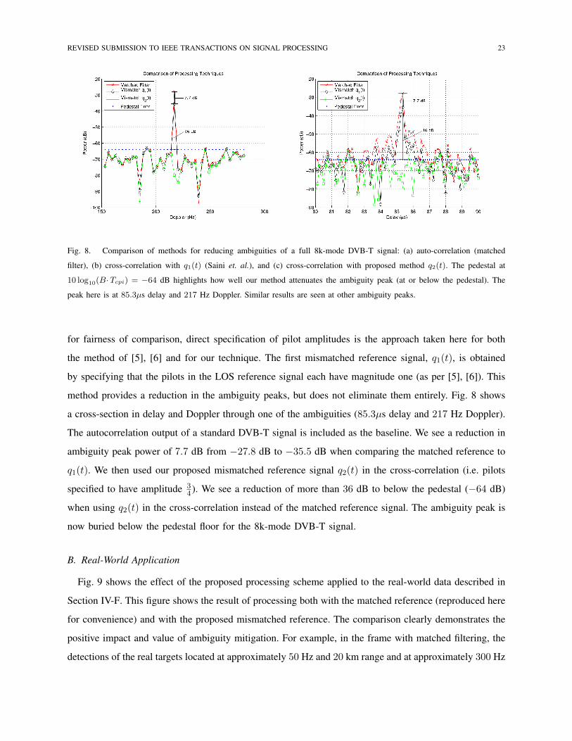
Fig. 8. Comparison of methods for reducing ambiguities of a full 8k-mode DVB-T signal: (a) auto-correlation (matched
filter), (b) cross-correlation with q1(t) (Saini et. al.), and (c) cross-correlation with proposed method q2(t). The pedestal at
10 log10(B·Tcpi) = −64 dB highlights how well our method attenuates the ambiguity peak (at or below the pedestal). The
peak here is at 85.3µs delay and 217 Hz Doppler. Similar results are seen at other ambiguity peaks.
for fairness of comparison, direct specification of pilot amplitudes is the approach taken here for both
the method of [5], [6] and for our technique. The first mismatched reference signal, q1(t), is obtained
by specifying that the pilots in the LOS reference signal each have magnitude one (as per [5], [6]). This
method provides a reduction in the ambiguity peaks, but does not eliminate them entirely. Fig. 8 shows
a cross-section in delay and Doppler through one of the ambiguities (85.3µs delay and 217 Hz Doppler).
The autocorrelation output of a standard DVB-T signal is included as the baseline. We see a reduction in
ambiguity peak power of 7.7 dB from −27.8 dB to −35.5 dB when comparing the matched reference to
q1(t). We then used our proposed mismatched reference signal q2(t) in the cross-correlation (i.e. pilots
specified to have amplitude 34 ). We see a reduction of more than 36 dB to below the pedestal (−64 dB)
when using q2(t) in the cross-correlation instead of the matched reference signal. The ambiguity peak is
now buried below the pedestal floor for the 8k-mode DVB-T signal.
B. Real-World Application
Fig. 9 shows the effect of the proposed processing scheme applied to the real-world data described in
Section IV-F. This figure shows the result of processing both with the matched reference (reproduced here
for convenience) and with the proposed mismatched reference. The comparison clearly demonstrates the
positive impact and value of ambiguity mitigation. For example, in the frame with matched filtering, the
detections of the real targets located at approximately 50 Hz and 20 km range and at approximately 300 Hz

REVISED SUBMISSION TO IEEE TRANSACTIONS ON SIGNAL PROCESSING 24
Range (monostatic approx lower bound) km
Dop
pler
(H
z)
0 10 20 30 40 50 60
−600
−400
−200
0
200
400
600
Range (monostatic approx lower bound) km
Dop
pler
(H
z)
0 10 20 30 40 50 60
−600
−400
−200
0
200
400
600
Fig. 9. CFAR Detection history with matched filter (left) and with a mismatched filter (right). The mismatched filter produces
a much cleaner detection history.
and 30-35 km range are competing with, or are being masked by, ambiguous returns. In contrast, when
the mismatched reference is used (right picture) the detections for both of these targets are unimpeded.
Many other examples are also apparent in the figure. Furthermore, in the case of the matched filter, there
are ambiguous returns of the helicopter and propeller-driven aircraft at zero-Doppler and 50 km delay
that behave like real targets and would therefore likely be tracked by any non-DVB-T specific tracking
algorithm. After processing via mismatched filtering, however, all traces of these returns (as well as all
of the other ambiguous returns) are unobservable.
VII. CONCLUSION
In conclusion, we have analyzed the use of DVB-T signals in passive radar systems. A DVB-T signal
has deterministic components that cause peaks in the ambiguity function at non-zero delay and varying
Doppler offsets. These peaks reduce the effectiveness of the radar system as they mask targets at these
offsets and/or contribute to false tracks in the radar system. We presented a detailed analysis of the DVB-
T waveform that shows how the deterministic components of the waveform cause these ambiguities. We
also proposed a scheme for pre-processing both the reference and surveillance signals obtained by the
passive radar to mitigate the effects of the ambiguities and clutter in range-Doppler processing. We then
demonstrated the effectiveness of our proposed scheme in enhancing target detection by using it on real-
world data taken from an (Australian) 8k-mode DVB-T system. We observed approximately a 29 dB
reduction in residual ambiguity levels over existing techniques, and approximately a 36 dB reduction

REVISED SUBMISSION TO IEEE TRANSACTIONS ON SIGNAL PROCESSING 25
over standard matched filtering while only incurring approximately a 1 dB reduction in the zero-delay,
zero-Doppler peak.
REFERENCES
[1] M. Cherniakov, Ed., Bistatic Radars: Emerging Technology. Wiley, 2008.
[2] J. Palmer, D. Merrett, S. Palumbo, J. Piyaratna, S. Capon, and H. Hansen, “Illuminator of opportunity bistatic radar research
at DSTO,” in IEEE International Conference on Radar, Sep. 2008, pp. 701–705.
[3] H. Griffiths and C. Baker, “Passive coherent location radar systems. part 1: Performance prediction,” in IEE Proc.-Radar
Sonar Navig., vol. 152, Jun. 2005, pp. 153–159.
[4] D. Poullin, “Passive detection using digital broadcasters (DAB, DVB) with COFDM modulation,” in IEE Proc.-Radar
Sonar Navig., vol. 152, Jun. 2005, pp. 143–152.
[5] R. Saini and M. Cherniakov, “DTV signal ambiguity function analysis for radar application,” in IEE Proc.-Radar Sonar
Navig., vol. 152, Jun. 2005, pp. 133–142.
[6] Z. Gao, R. Tao, Y. Ma, and T. Shao, “DVB-T signal cross-ambiguity functions improvement for passive radar,” in Radar,
2006 International Conference on, Oct. 2006, pp. 1–4.
[7] J. Palmer, S. Palumbo, A. Summers, D. Merrett, and S. Howard, “DSTO’s experimental geosynchronous satellite based
PBR,” in IEEE International Conference on Radar, 2009.
[8] C. R. Berger, B. Demissie, J. Heckenbach, P. Willett, and S. Zhou, “Signal processing for passive radar using ofdm
waveforms,” J. Sel. Topics Signal Processing, pp. 226–238, 2010.
[9] D. F. Crouse, “A time-shift model for ofdm radar,” Proceedings of the IEEE Radar Conference, pp. 841–846, 2012.
[10] J. Raout, “Sea target detection using passive DVB-T based radar,” in Radar, 2008 International Conference on, Sep. 2008,
pp. 695–700.
[11] Digital Video Broadcasting (DVB); Framing structure, channel coding and modulation for digital terrestrial television
(DVB-T), 1st ed., European Telecommunications Standards Institute, Mar. 1997.
[12] C. Bongioanni, F. Colone, D. Langellotti, P. Lombardo, and T. Bucciarelli, “A new approach for DVB-T cross-ambiguity
function evaluation,” in EuRAD Proceedings, vol. 6, Rome, Italy, Oct. 2009, pp. 37–40.
[13] H. Harms, L. Davis, and J. Palmer, “Understanding the signal structure in DVB–T signals for passive radar detection,” in
IEEE Radar Conference, May 2010.
[14] Digital Television-Terrestrial Broadcasting, 2nd ed., Standards Australia, May 2007.
[15] H. A. Harms, J. E. Palmer, S. J. Searle, and L. M. Davis, “Impact of quantization on passive radar target detection,” in
IET International Radar Conference on Radar Systems, Oct. 2012, accepted for publication.
[16] M. Skolnik, Radar handbook, 3rd ed. New York: McGraw-Hill, 2008.
[17] J. Palmer, S. Palumbo, A. Summers, D. Merrett, S. Searle, and S. Howard, “An overview of an illuminator of opportunity
passive radar research project and its signal processing research directions,” Digital Signal Processing, vol. 21, no. 5, pp.
593 – 599, 2011.
[18] S. Searle, S. Howard, and J. Palmer, “Remodulation of DVB–T signals for use in passive bistatic radar,” in 44th Asilomar
Conf. on Signals Systems and Computers, Nov. 2010, pp. 1112–1116.
[19] “Digital television – terrestrial broadcasting part 1: Characteristics of digital terrestrial television transmissions,” australian
Standard AS4599.1–2007.

REVISED SUBMISSION TO IEEE TRANSACTIONS ON SIGNAL PROCESSING 26
[20] “Digital video broadcasting (DVB); framing structure, channel coding and modulation for digital terrestrial television
(DVB-T),” ETSI EN 300 744.
[21] S. Haykin, Adaptive Filter Theory, 4th ed. New Jersey: Prentice Hall, 2002.