review of test methods - europa · 2 d3.2 review of test methods executive summary the present...
TRANSCRIPT

FP7-FCH-JU-2011-1 -303422
1
MATHRYCEMaterial Testing and Recommendations for Hydrogen Components
under fatigue
Deliverable D3.2Nature OtherDissemination CO - Confidential
Review of test Methods
Foreseen submission date Project Month 8 – May, 31, 2013
Actual submission date Project Month 18 – March, 31, 2014
Author(s) Jussi Solin – VTT
Andrew Roiko – VTT
Version number for EC V1
Doc ID Code MATHRYCE_ D3.2_2013-05-31_V1
Contract Start Date 2012-10-01
Duration 36 months
Project Applicant CEA - LITEN
FCH Joint Undertaking CollaborativeProject
Project funded by the European Commission

2
D3.2 Review of test methods
EXECUTIVE SUMMARYThe present deliverable contains a review of current test methods used for validation of materials for
pressure equipment. The particular demands on the design methods and material data caused by highsafety concerns and material – hydrogen interaction and experimental limitation due to high pressurehydrogen are discussed. The consortium test strategies and capabilities are assessed and found not
secured to success, but relevant to address the challenges. The partners are aiming to contribute to thestate of the art by globally best available knowledge and technology.
Project Number FP7- FCH JU – 2011 – 1 - 303422
Project Acronym MATHRYCE
Title Material Testing and Recommendations for Hydrogen Components under fatigue
Deliverable N° D3.2
Due Date Project Month 8
Delivery Date Project Month X – Month, Day, 2013
SHORT DESCRIPTION as per the DoW:The present deliverable contains a review of current test methods used for validation of materials forpressure equipment. The particular demands on the material data and experimental limitation due tohigh pressure hydrogen are discussed and based on this an assessment of the consortium teststrategies and capabilities are assessed.
Document Control
Title: D3.2 Review of test methods
Project: MATHRYCE
Type: Report Dissemination CO
The information contained in this report is subject to change without notice and should not be construedas a commitment by any members of the MATHRYCE Consortium. The MATHRYCE Consortiumassumes no responsibility for the use or inability to use any procedure, protocol, which might bedescribed in this report. The information is provided without any warranty of any kind and theMATHRYCE Consortium expressly disclaims all implied warranties, including but not limited to theimplied warranties of merchantability and fitness for a particular use.
AuthorsJussi Solin - VTT
Andrew Roiko - VTT

3
D3.2 Review of test methods
Doc ID MATHRYCE_ D3.2_2013-05-31_V1
Amendment HistoryVersion Date Author Description/CommentsV1 August, 12,
2013Jussi Solin - VTTAndrew Roiko - VTT
Abstract
This deliverable D3.2 “Review of test methods” will define the type and design of test specimen,instrumentation and experimental conditions to be employed in order to achieve the most efficientcharacterization of material and its applicability for use in hydrogen high pressure vessels. Due to the factthat the test method, specimen size and number of tests in high pressure hydrogen gas will be limited, andconsidering that the monitoring of fatigue damage during a high pressure hydrogen test is challenging, anoptimization of the test methods and instrumentation is important. The review and critical assessment ofdifferent test methods used for general validation is summarized in this report. The special demands onmaterial data and experimental limitations due to high pressure hydrogen are discussed and based on thisthe test capabilities of the consortium assessed.

4
D3.2 Review of test methods
Table of contents
1 INTRODUCTION ............................................................................................................................................ 51.1 AIM OF THE WORK ..................................................................................................................................... 51.2 THE CHALLENGE – PERFORMANCE IN OPERATIONAL CONDITIONS .................................................................... 5
2 TESTING FOR FATIGUE DESIGN OF PRESSURE EQUIPMENT .................................................................. 72.1 HISTORICAL PERSPECTIVE ......................................................................................................................... 72.2 DESIGN BY ANALYSIS................................................................................................................................. 7
2.2.1 Stress based approaches ................................................................................................................... 72.2.2 Damage tolerant approach and fracture mechanics............................................................................. 82.2.3 Local strain approach.......................................................................................................................... 8
2.3 ALTERNATIVE MATERIAL TESTING METHODS ................................................................................................. 92.3.1 Role of inclusions in the steel .............................................................................................................. 92.3.2 Focusing in initiation or growth of the crack ......................................................................................... 92.3.3 Microscopic local strain approach ....................................................................................................... 92.3.4 Growth of short cracks ...................................................................................................................... 10
2.4 MATERIAL TESTING METHODS TO BE DEVELOPED ........................................................................................ 103 TESTING IN HYDROGEN ............................................................................................................................ 13
3.1 SAFETY CONCERN .................................................................................................................................. 133.2 HYDROGEN – METAL INTERACTION EFFECTS .............................................................................................. 13
3.2.1 Gas pressure .................................................................................................................................... 133.2.2 Gas composition ............................................................................................................................... 133.2.3 Frequency, temperature and loading ratio (R) ................................................................................... 133.2.4 ASME section VIII, Division 3:2007 standard ..................................................................................... 13
4 SPECIFIC TEST METHODS TO BE CONSIDERED ..................................................................................... 154.1 CRACK INITIATION ................................................................................................................................... 154.2 CRACK GROWTH ..................................................................................................................................... 154.3 CRACK MONITORING ............................................................................................................................... 154.4 DISK PRESSURE TEST .............................................................................................................................. 16
5 REFERENCES ............................................................................................................................................. 17

5
D3.2 Review of test methods
1 INTRODUCTION
1.1 Aim of the workThe main objectives of the MATHRYCE project are centred on the development (and dissemination forstandardization) of a methodology for the design of hydrogen high pressure metallic vessels and for their lifetimeassessment (that takes into account hydrogen-enhanced fatigue). This needs to be achieved without requiring fullscale component testing under hydrogen (as this is not feasible considering the expected cycle lives andequipment size). The project therefore targets the justification of an approach where lifetime assessment resultsfrom combining the hydraulic cycling performance of the component with the appropriate knowledge of theperformance of the metallic material in hydrogen under cyclic loading.
This approach will be validated by comparing the lifetime prediction of a component calculated from the lab-scaletests to that obtained from large scale component tests. The analysis of the results, based on numericalsimulations as well as on the scientific knowledge of the possible hydrogen embrittlement mechanisms, will allow toassess or to modify the proposed design methodology.
Once the testing method as well as the associated design methodology is validated, specific recommendations willbe proposed for implementation in international standards.
To summarize, the main outcomes of the MATHRYCE project will be:- The development of a reliable testing method to characterize materials exposed to hydrogen-enhanced
fatigue.- The experimental implementation of this testing approach, generating extensive characterization
(microstructural and mechanical) of metallic materials for hydrogen service.- The definition of a methodology for the design of metallic components exposed to hydrogen enhanced
fatigue and for the assessment of their service lifetime. This methodology is liable to be recognized forpressure equipment regulation.
- The dissemination of this methodology, as a proposed approach for standardization.- The dissemination of prioritized recommendations for the implementation in international standards.
Review of the relevant standards and current state of the art in design of hydrogen pressure equipment is a topicfor another task within the MATHRYCE project. For this report we reviewed globally accepted design methods andgeneric pressure equipment design codes to evaluate the role of material performance and fatigue testingprocedures in safe design of non-fired pressure vessels.
1.2 The challenge – performance in operational conditionsWhen summarizing the current situation, the European Industrial Gases Association (EIGA) listed the main factorsthat influence hydrogen embrittlement of a hydrogen pressure vessel [1]. The material and design aspects areshown schematically on the right hand side of Figure 1. Management of those issues is the responsibility ofcylinder designer and manufacturer, but for successful and safe design, the designer must carefully consider alsothe use of the vessel, the left hand side of Figure 1.
According to the present knowledge within the EIGA, “probable cause for the early failure of hydrogen cylinders isfatigue, accelerated by hydrogen embrittlement.” The importance of hydrogen enhanced fatigue and understandingof the related mechanisms is emphasized by stating: “This crack initiation process is favoured by the slow strain-rate that the cylinder wall is subjected to during filling with gas and pressurisation by hydrogen. The crack initiationprocess is also affected by the existing microstructure. With a more stable microstructure the generation of fatiguecracks is more difficult.” [1]
Our challenge is to define, develop and verify test methodology, which is able to support the design and safetyassessment taking into account the factors presented in Figure 1.

6
D3.2 Review of test methods
Figure 1: Factors influencing hydrogen induced cracking. [1]
7
D3.2 Review of test methods
2 TESTING FOR FATIGUE DESIGN OF PRESSURE EQUIPMENT
2.1 Historical perspectiveA concept of proof pressure test was developed 200 years ago to improve safety of the steam boilers running thesteam engines and industrial revolution. Mandatory pressure test was prescribed in France in 1823 [2]. Themanufactures were later given freedom to select the materials and wall thicknesses with the condition that theboiler resists a pressure test, which was – at the time – the only effective means available to the regulators toensure the adequacy of the design and fitness-for-service. Later on, more sophisticated methods have beendeveloped for design, inspection and regulation. Different methods may be combined to build a “Defence in depth”strategy for ensuring safety of critical pressure equipment. “Primary level” design methods are used to decide onallowable stresses and vessel dimensions. “Secondary level” methods are to verify fitness for service of a readydesigned vessel or set criteria for in-service inspection, e.g. to avoid fracture due to unexpected crack growth.
Full scale pressure test has retained its value, first as a primary, later as a secondary level verification of fitness forservice. Cyclic hydraulic tests can be used to ensure fitness for cyclic service, but this is expensive and timeconsuming. In case of hydrogen storage tanks, testing of complete vessels will play important role for safety until afatigue design concept with relevant material specifications is developed and found globally acceptable. However,vessel tests are not effective to research and develop material performance with hydrogen interaction. Analternative solution would be a design approach based on modern stress analysis and material performance in realconditions, supported by full scale tests for verification of fitness for service on the secondary level.
2.2 Design by analysisThe nuclear industry provides one model solution. The book “Criteria of the ASME Boiler and Pressure VesselCode for design by analysis in sections III and VIII division 2” [3] describes the design by analysis philosophybehind the ASME III code and similar European codes used for safety critical pressure equipment. These codesare not directly applicable for hydrogen vessels, but the role of material testing in the ASME code is of interest forthe discussion in the MATHRYCE project.
We can find common challenges in the design of hydrogen and nuclear pressure vessels. The design pressuresmay be much higher for hydrogen vessels, but safety is a similarly important concern for both vessel types. In bothcases we have a concern on embrittlement during operation. Science-based understanding of materialperformance and its potential changes after manufacture is necessary. Furthermore, we know that similaroperational conditions such as temperature, environment, stress state and loading rate affect the fatiguemechanisms and material performance. Metal fatigue research in operational conditions has been found necessaryto ensure safe design of the pressure equipment. But realistic simulation of the operational conditions in materialsresearch laboratory is not easy. This has been a challenge for 3 decades in nuclear materials research. And it is achallenge for us today. Therefore, fatigue testing in realistic operational conditions is in focus of the MATHRYCEproject.
2.2.1 Stress based approachesSome rotating machinery and other components loaded by very high numbers of well-defined stress cycles aredesigned against a fatigue limit and its statistical reliability, e.g. mean stress amplitude leading to fatigue life Nf .107 cycles minus 2 or 3 standard deviation.
For finite life range or variable amplitude loading fatigue assessment normally utilises S-N curves. “S” being eitherstress or strain amplitude (or range). “Wöhler curves” originally introduced by August Wöhler, who studied fatigueof railway axles, are well known and generally assumed to model material performance in stress-life coordinates.But the original Wöhler curves reported component tests and also today, stress-life curves are commonly used forwelded joints or other structural details. Fatigue loading is there defined as nominal or fictitious (hot spot) localstress. Naturally, stress-life curves and load controlled smooth specimen tests are also used for selected purposes.

8
D3.2 Review of test methods
2.2.2 Damage tolerant approach and fracture mechanicsAircraft industry is known to apply damage tolerant design approaches. Defects are assumed to exist from thebeginning and/or fatigue cracks are assumed to initiate and potentially grow already during the safe life. Fracturemechanics are used to model and predict postulated crack growth rates. Allowable inspection intervals can bedetermined.
Versions of damage tolerant design approaches are applied also for pressure equipment. The primary level designis still based on S-N curves, but additional redundancy and periodic inspection strategies are justified by fracturemechanics assessment. Crack growth rate and its dependence on the operational conditions shall be known. Thishas motivated fatigue crack growth testing in pressure hydrogen environment. Compact tension (CT) specimensare often found convenient for the purpose.
2.2.3 Local strain approachAutomotive industry normally uses strain controlled endurance data in form of strain-life curves together with cyclicstress-strain curves needed for local strain calculation in notches or other strain concentrations. The fatigue designapproaches in automotive industry are generally referred as “local strain approach” and justified by the fact thatfatigue is caused by strain variation. Cyclic plastic strain is known to provide the best correlation with fatigue life.
For fatigue design according to ASME III [4], the allowable loading is given in form of design curves, which arebased on strain controlled low cycle fatigue tests [5]. Similar curves are applied also in other design codes forpressure equipment, e.g., the German KTA and French RCC-M. The design approach is based on a local strainapproach, but modified to look like a stress based approach. The vertical axis strain units are translated to quasi-elastic stress units for “stress intensity”. A temperature dependent elastic modulus is applied to total strain(including also plastic strain). This yields to very high values of stress intensity amplitudes allowable for short lives.Stress amplitudes measured in laboratory test are not comparable to the design curve. For stainless steels, whichexperience notable nonlinear strain even at endurance limit, this is true even in high cycle regime. All fatigue dataused for design shall be strain based.
Figure 2 shows the rationale for adopting a version of local strain approach for ASME III design. Similar shape offatigue curve makes strain controlled data better transferable to components than stress controlled data. Fatigueendurance depends on the local strain, which can be calculated by nominal loading and almost constant strainconcentration factor. The material yields at a stress concentration, but being surrounded by elastic displacementsthe material locally experiences strain control also when the component is loaded under stress or load control.
Figure 2. Transferability of strain or stress controlled data tocomponent behaviour in low cycle fatigue regime. [3]

9
D3.2 Review of test methods
2.3 Alternative material testing methods
2.3.1 Role of inclusions in the steelLet’s turn back to the case of load controlled fatigue tests for smooth axial bars. A closer look into the crackinitiation sites and fatigue mechanisms reveals that at the microscopic level, fatigue is controlled by local strainseven in these tests. The famous book of our Japanese collaboration partner, Murakami sensei thoroughlydescribes how high cycle fatigue is often initiated at small inclusions in steel. This is observed in specimenscontaining no other preferred initiation sites [6]. We can assume that a spherical inclusion causes an elastic stressconcentration with a factor of 3. If the nominal fatigue limit is approaching half of the ultimate tensile strength, afactor of 3 would increase the local stress beyond the ultimate strength of the material. This means that cyclicyielding occurs at a close distance from the inclusion, and further that there is a zone experiencing strain controlledcyclic deformation. The bigger the inclusion, the bigger are the dimensions of the strain concentration volume andthe lower is the fatigue limit. Very small inclusions can become decisive for long lives, large inclusions or otherdefects are effective even in the low cycle fatigue range.
Murakami also reports experimental evidence on hydrogen diffusion and trapping to the inclusions [6]. This must beconsidered together with the fact that the hydrogen content is highest at the inner surface of a high pressurehydrogen containing vessel. Hydrogen diffusion rate is relatively fast in ferritic pressure vessel steels, which areselected as the focus for the MATHRYCE project. Hydrogen intake at the inner surface and release at the outersurface create a macroscopically linear gradient of hydrogen content through the wall thickness. Hydrogen trappingand stress gradients increase hydrogen content locally.
For safe fatigue design, we indeed need to assess the probability and consequences of finding an inclusion (orother defect) at the immediate vicinity of the inner surface, because – even without hydrogen gradient – this resultsto the minimum endurance limit of the specimen or component. And this conclusion is further emphasized with thelocally high concentration and detrimental role of hydrogen in fatigue initiation from inclusions.
2.3.2 Focusing in initiation or growth of the crackWe know that from the mechanisms point of view fatigue life cannot be separated into initiation and crack growthphases without some arbitrary definition of the borderline. Engineering judgment and ability to detect by non-destructive methods are normally used to distinguish between the “initiation” and growth. This is actually animportant border line, because different design approaches will be selected depending on which side of the borderwe position the designer. Do we intend to prevent crack “initiation” or growth of an early initiated crack? In fact, weneed to do both, but let’s first consider these challenges one by one.
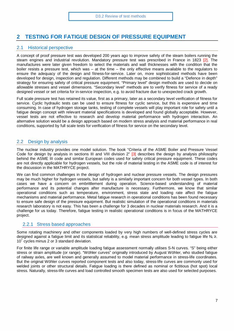
2.3.3 Microscopic local strain approachWhen considering just crack “initiation” from an inclusion, the inclusion can be considered as a small notch. Tosimulate an inclusion, a notch can also be intentionally machined to a laboratory test specimen, e.g. by drilling as inthe “Murakami type” specimens, Figure 3. Elastic stress concentration at the notch will cause cyclic small scaleplastic yielding surrounded by elastic material. If we can assume the material as a continuum, we can model thestress strain response similar to a macroscopic notch and apply local strain approach. In the context of Figure 2,the smooth bar with notch becomes a “component” and we actually perform a strain controlled initiation test, eventhough we control the load amplitude introduced to the specimen.
To our knowledge, no laboratory is currently able to perform strain controlled axial tension compression low cyclefatigue tests in high pressure hydrogen environment [5]. This would be needed, if the vessel design procedurerequest to perform strain controlled tests for finite lives, as some pressure equipment design codes do. Introducinga small (but not too small) notch could provide an indirect method to approximate strain controlled situation at thelocation, where crack initiates.
Unfortunately, reality is more complex than described above. The stress strain field is not uniform and the gradientsmay also play a role. The total volume exposed to relevant fatigue straining is very small and if the notchdimensions are close to the microstructural characteristic dimensions, the continuum assumption is not valid. But incase of small grain sized material (similar to the test material in our project) we may select a drill diameter sufficientlarge to consider testing of notched specimens for “initiation”.
10
D3.2 Review of test methods
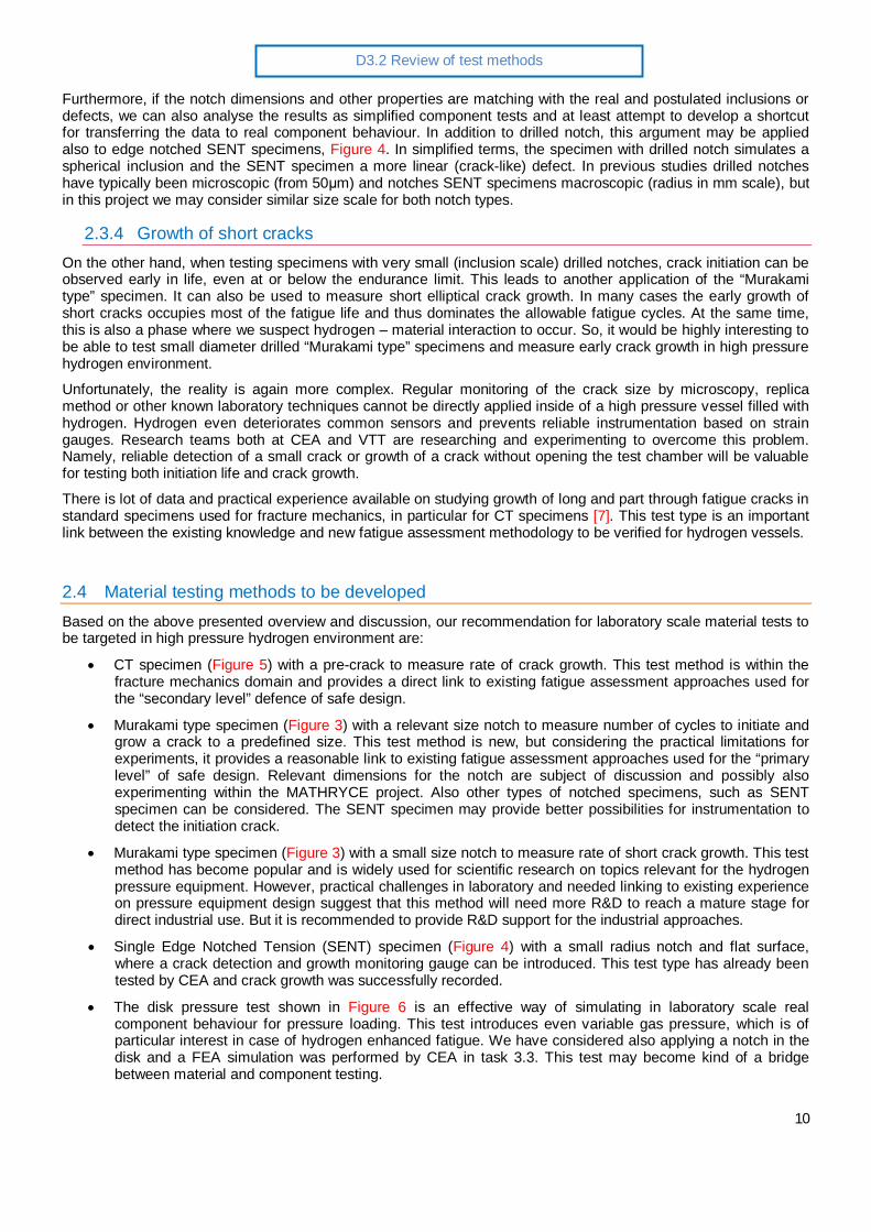
Furthermore, if the notch dimensions and other properties are matching with the real and postulated inclusions ordefects, we can also analyse the results as simplified component tests and at least attempt to develop a shortcutfor transferring the data to real component behaviour. In addition to drilled notch, this argument may be appliedalso to edge notched SENT specimens, Figure 4. In simplified terms, the specimen with drilled notch simulates aspherical inclusion and the SENT specimen a more linear (crack-like) defect. In previous studies drilled notcheshave typically been microscopic (from 50 m) and notches SENT specimens macroscopic (radius in mm scale), butin this project we may consider similar size scale for both notch types.
2.3.4 Growth of short cracksOn the other hand, when testing specimens with very small (inclusion scale) drilled notches, crack initiation can beobserved early in life, even at or below the endurance limit. This leads to another application of the “Murakamitype” specimen. It can also be used to measure short elliptical crack growth. In many cases the early growth ofshort cracks occupies most of the fatigue life and thus dominates the allowable fatigue cycles. At the same time,this is also a phase where we suspect hydrogen – material interaction to occur. So, it would be highly interesting tobe able to test small diameter drilled “Murakami type” specimens and measure early crack growth in high pressurehydrogen environment.
Unfortunately, the reality is again more complex. Regular monitoring of the crack size by microscopy, replicamethod or other known laboratory techniques cannot be directly applied inside of a high pressure vessel filled withhydrogen. Hydrogen even deteriorates common sensors and prevents reliable instrumentation based on straingauges. Research teams both at CEA and VTT are researching and experimenting to overcome this problem.Namely, reliable detection of a small crack or growth of a crack without opening the test chamber will be valuablefor testing both initiation life and crack growth.
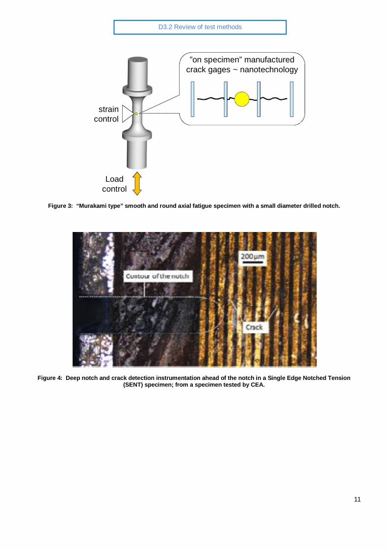
There is lot of data and practical experience available on studying growth of long and part through fatigue cracks instandard specimens used for fracture mechanics, in particular for CT specimens [7]. This test type is an importantlink between the existing knowledge and new fatigue assessment methodology to be verified for hydrogen vessels.
2.4 Material testing methods to be developedBased on the above presented overview and discussion, our recommendation for laboratory scale material tests tobe targeted in high pressure hydrogen environment are:
CT specimen (Figure 5) with a pre-crack to measure rate of crack growth. This test method is within thefracture mechanics domain and provides a direct link to existing fatigue assessment approaches used forthe “secondary level” defence of safe design.
Murakami type specimen (Figure 3) with a relevant size notch to measure number of cycles to initiate andgrow a crack to a predefined size. This test method is new, but considering the practical limitations forexperiments, it provides a reasonable link to existing fatigue assessment approaches used for the “primarylevel” of safe design. Relevant dimensions for the notch are subject of discussion and possibly alsoexperimenting within the MATHRYCE project. Also other types of notched specimens, such as SENTspecimen can be considered. The SENT specimen may provide better possibilities for instrumentation todetect the initiation crack.
Murakami type specimen (Figure 3) with a small size notch to measure rate of short crack growth. This testmethod has become popular and is widely used for scientific research on topics relevant for the hydrogenpressure equipment. However, practical challenges in laboratory and needed linking to existing experienceon pressure equipment design suggest that this method will need more R&D to reach a mature stage fordirect industrial use. But it is recommended to provide R&D support for the industrial approaches.
Single Edge Notched Tension (SENT) specimen (Figure 4) with a small radius notch and flat surface,where a crack detection and growth monitoring gauge can be introduced. This test type has already beentested by CEA and crack growth was successfully recorded.
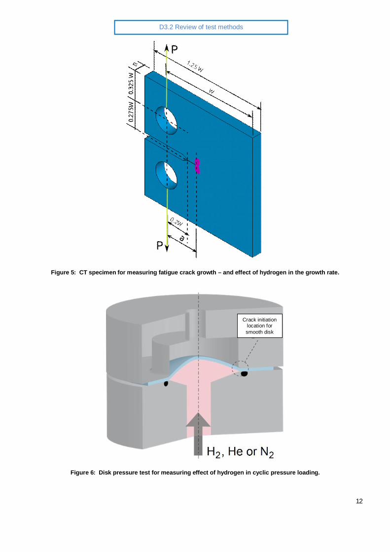
The disk pressure test shown in Figure 6 is an effective way of simulating in laboratory scale realcomponent behaviour for pressure loading. This test introduces even variable gas pressure, which is ofparticular interest in case of hydrogen enhanced fatigue. We have considered also applying a notch in thedisk and a FEA simulation was performed by CEA in task 3.3. This test may become kind of a bridgebetween material and component testing.
11
D3.2 Review of test methods
”on specimen” manufacturedcrack gages ~ nanotechnology
Loadcontrol
straincontrol
Figure 3: “Murakami type” smooth and round axial fatigue specimen with a small diameter drilled notch.
Figure 4: Deep notch and crack detection instrumentation ahead of the notch in a Single Edge Notched Tension(SENT) specimen; from a specimen tested by CEA.
12
D3.2 Review of test methods
Figure 5: CT specimen for measuring fatigue crack growth – and effect of hydrogen in the growth rate.
Figure 6: Disk pressure test for measuring effect of hydrogen in cyclic pressure loading.
Crack initiationlocation forsmooth disk

13
D3.2 Review of test methods
3 TESTING IN HYDROGEN
3.1 Safety concernHydrogen is a rapidly burning gas and when using pressurised hydrogen as a testing environment, ventilation, leakdetection and other precaution measures need to be adopted. Safety needs always be taken into consideration, butit is not the focus of this report and will not be further discussed.
3.2 Hydrogen – metal interaction effectsPressurised hydrogen subjected to metallic material surface affects material performance. Therefore we need toperform fatigue tests under relevant hydrogen pressure.
3.2.1 Gas pressureThe amount of pressure in a hydrogen gaseous environment directly affects the crack growth rate and fatigue life ofthe material. Typically a higher pressure will induce a faster rate of crack growth which can increase from a factorof 10 to 70 times the typical growth rate in air and in similar loading conditions. [8]
3.2.2 Gas compositionThe amount of oxygen or water in the hydrogen during testing may have a dramatic effect on the crack growth rateof the material. Addition of O2 or CO will retard the crack growth rates to those that are similar to air. One studyhas shown that an addition of 0.1% O2 will decrease the growth rate to less than 20% of what it would be in a purehydrogen atmosphere [9]. Other tests have shown that using hydrogen gas mixed with some amount of moisturegave results that were comparable to air [10].
3.2.3 Frequency, temperature and loading ratio (R)A decrease in the testing frequency will increase the crack growth rate in hydrogen atmosphere. This can beexplained by more time for diffusion of hydrogen to the crack tip.
At elevated temperatures hydrogen can dissociate into atomic form and enter the material much more rapidly. Alsosolubility of hydrogen to metals depends on temperature. However, tests done on a pressure vessel steel showedthe effect of hydrogen over a range from 23 C to 85C and over a range of frequencies showed that the accelerationof the crack growth rate was reduced at elevated temperatures, and that at 85 C in a hydrogen atmosphere thecrack growth rate was similar to that measured in air. [11]
An increase in the crack growth rate is reported with increasing loading ratios, although this correlation is not asstrong as it is in air. [10] The effect of loading ratio remains to be studied.
3.2.4 ASME section VIII, Division 3:2007 standardThe new ASME Section VIII Division 3 standard is mandatory for the following vessels and materials:
a) Non-welded vessels: with hydrogen partial pressure exceeding 6000psi (41.3 MPa); with actual UTS exceeding945MPa and hydrogen partial pressure exceeding 750psi (5.2MPa).
b) Welded construction with hydrogen partial pressure exceeding 2500psi (17.2 MPa); with actual UTS exceeding620MPa and hydrogen partial pressure exceeding 750psi (5.2MPa).
This new rule requires that the properties of materials to be used in high pressure hydrogen should have theirmaterial properties of fatigue crack growth rate and fracture resistance determined in hydrogen gaseousatmosphere at a pressure that is not less than the design pressure of the vessel.

14
D3.2 Review of test methods
Other requirements of the ASME standard are:
Test specimens with a grain orientation of TL are to be preferred for the base metal.
The testing chamber should be emptied of any traces of air or moisture that has been absorbed by thewalls of the chamber or anything in the chamber.
The hydrogen gas in the chamber should be measured at the end of the test. The limits of the impurities inthe gas are as follows: O2<1ppm, CO2<1ppm, and H2O<3ppm.
The testing frequency should be applied according to the design specifications. A testing frequency greaterthan 0.1Hz is not recommended.

15
D3.2 Review of test methods
4 SPECIFIC TEST METHODS TO BE CONSIDERED
4.1 Crack initiationTo determine the effect of non-metallic inclusions or defects on the fatigue limit of steels a method along with atheory was developed by Prof. Murakami in Kyushu University, Japan. This method introduces a small drilled holeinto the test specimen and the theory predicts the fatigue limit of the steel based on the hardness of the steel andthe square root of the projected area normal to the stress. See Deliverable 2.1 for more details.
The research teams in Kyushu University use Prof. Murakami’s testing method of drilling a small hole usually from100 to 500 microns in diameter and typically the depth of the hole is equal to its diameter. This hole is used toinitiate a fatigue crack. After crack initiation the replica method is used to follow the crack growth during the fatiguetest. This is done by interrupting the fatigue test and placing a small plastic replica that takes a very exact negativeof the surface of test specimen. This small replica of the surface is a permanent record of the surface of the test barand can be used to measure the crack length. [13]
The replica method is a little time consuming, but convenient method of recording the crack formation and growthduring tests in ambient air. However, this is not possible inside a pressure vessel and another kind of crackmonitoring is needed for testing in pressurised hydrogen.
4.2 Crack growthAnother interesting method is used at Kyushu University for testing fatigue crack growth. It is summarised asfollows:
There is provided a fatigue test method with which the crack growth can be checked for a plurality of cycle rates ina single test. At a first cycle rate f1 of 0.01 Hz, hydrogen has a greater effect on crack growth than at a secondcycle rate f2 of 1 Hz. As a result, an area of large hydrogen effect (an area developed at the cycle rate f1) and anarea of small hydrogen effect (an area developed at the cycle rate f2) appear alternately on the fatigue fracturesurface, and since these two areas have different fracture surface morphologies, it is possible to see the boundarylines. Consequently, the lengths of the cracks developed under each set of conditions can be specified, and afatigue crack growth curve can be acquired for each set of conditions. [FATIGUE TESTING METHOD INHYDROGEN GAS, Patent application EP 2 233 911 A1]
4.3 Crack monitoringIn this project we are attempting to develop new kind of instrumentation to detect crack initiation in a notched“Murakami type” specimen (VTT) and to follow crack growth in a CT- or SENT specimen (CEA). VTT and CEA arecurrently exploring electrical and optical methods suitable for monitoring cracks (initiation as well as propagation)both in small scale specimens and components – and applicable to used inside a pressurised hydrogen vessel.Tests are going on with specimens with miniature crack gage sensors. Similar technology scaled to largerdimensions will then be evaluated for component tests.
Many challenges remain because only limited number of instrumentation approaches have been found reliable inair and they have not yet been applied in high pressure hydrogen. CEA has successfully tested crack gages with0,1 mm step and applicable for SENT specimen flat surface specimens. VTT is working on a sensor that can beapplied on round surface of axial test bars. These sensors shall give a reliable and definite signal when crackpasses through the sensor, Figures 3 and 4. This sensor shall not be sensitive to high pressure hydrogen. Acommercial crack gage not designed for this application is being evaluated in parallel. This mm –scale gage is notapplicable for the round bar specimens, but it might be applicable for CT type specimens and/or components, ifcrack detection and tolerance for hydrogen atmosphere can be verified. However, one more (and unsolved)problem is, how to attach and accurately position the sensors on the inner surface of the vessel, which has only asmall diameter entry point. These challenges have been discussed together with the partners performing thecomponent tests.

16
D3.2 Review of test methods
4.4 Disk pressure testThe disk pressure test (Figure 6) combined with numerical simulation of the test is considered as a promisingmethod to simulate real pressure boundary behaviour in pressure loading and bridge material and componentperformance in laboratory scale.
This test can also be considered as a method to verify existing state of the art and factors used to correlate deepand shallow cycles in pressure tests. Cyclic hydraulic tests are normally performed using deep cycles ranging froma low pressure to maximum allowable pressure. However, the service loading of many components does not followthis scheme. In particular, the buffer tank in a hydrogen refilling station will experience small drops of pressureduring refuelling of cars and the compressor will regularly fill in to retain the desired buffer pressure. This creates alarge number of shallow cycles. The mechanical loading can be characterised as high stress ratio (R>>0). Alsohydrogen pressure remains high during the whole cycle and this raises another concern on correlation of deep andshallow cycles in pressure tests and operation. This issue could probably be effectively studied through shallowcycle disk pressure tests with hydrogen.

17
D3.2 Review of test methods
5 REFERENCES
1. EIGA, European Industrial Gases Association: “Hydrogen Cylinders and Transport Vessels”, IGC Doc100/03/E, revision of TN 26/81. 38 pages.
2. Ordonnance du Roi, portent règlement sur les machines à vapeur à haute pression, October 29, 1823.(French regulation)
3. Criteria of the ASME Boiler and Pressure Vessel Code for design by analysis in sections III and VIII division2. Pressure Vessels and Piping: Design and Analysis, A Decade of Progress, Vol. 1 ASME 1972, p. 61-83.
4. ASME Code, Sections III and VIII, Divisions 1, 2 and 3. American Society of Mechanical Engineers, NewYork. & Addendum 2009b: Section III Division 1, Mandatory Appendix 1 Design Fatigue Curves.
5. ASTM Standard E-606M-12, “Standard Test Method for Strain-Controlled Fatigue Testing”, ASTMInternational, West Conshohocken, PA, 2012.
6. Murakami, Y., Metal Fatigue: Effects of Small Defects and Non-metallic Inclusions. Elsevier, 2002. ISBN:978-0-08-044064-4, 384 Pages.
7. ASTM-E647-01,”Standard test Method for Measurement of Fatigue Crack Growth Rates”, Annual Book forASTM Standards, Vol.3.01, E647, American Society for Testing and Materials, WestConshohochen,PA,2001.
8. Holbrook J H, Cialone H J, Mayfield M E and Scott P M, 1982: 'Effect of hydrogen on low-cycle-fatigue lifeand subcritical crack growth in pipeline steels', Research report from Battelle Columbus Laboratories,Columbus, OH 43201, USA, Report No.: BNL-35589 (DE5006685)
9. Fukuyama S and Yokogawa K, 1992: 'Prevention of hydrogen environmental assisted crack growth of2.25Cr-1Mo steel by gaseous inhibitors', in Pressure Vessel Technology, Essen, Germany, Vol.2, pp.914-923.
10. Suresh S and Ritchie R O, 1982: 'Mechanistic dissimilarities between environmentally influenced fatiguecrack propagation at near threshold and higher growth rates in lower strength steels', Metal Science,Vol.16, No.11, pp.529-538.
11. Stewart A T, 1977: 'Effect of hydrogen on fatigue crack propagation in steels', Proc. of the Inter. Conf. onthe Mechanisms of Environment Sensitive Cracking in Materials, University of Surry, 4-7 April 1977,pp.400-411.
12. Yan Hui Zhang, 2010: 'Review of the effect of hydrogen gas on fatigue performance of steels', 29thInternational Conference on Offshore Mechanics and Arctic Engineering (OMAE 2010), Shanghai, China,6-11 June 2010.
13. Arnaud Macadre, Hiroki Yano, Saburo Matsuoka, Jader Furtado, 2011: The effect of hydrogen on thefatigue life of Ni–Cr–Mo steel envisaged for use as a storage cylinder for a 70 MPa hydrogen station,International Journal of Fatigue, Volume 33, Issue 12, December 2011, Pages 1608-1619, ISSN 0142-1123, http://dx.doi.org/10.1016/j.ijfatigue.2011.07.007.(http://www.sciencedirect.com/science/article/pii/S0142112311001903)