review of network basics & common protocols infsci 1075: network security amir masoumzadeh
TRANSCRIPT

Review of Network Basics & Common Protocols
INFSCI 1075: Network Security
Amir Masoumzadeh

2
Outline What is a computer network? OSI reference model TCP/IP Network Protocols

3
What is a Computer Network? A network is a collection of end systems,
interconnected by intermediate systems

4
What is a Computer Network? Software and hardware infrastructure
Allow access to different types of resources (original purpose) Computing resources, input/output devices, files,
databases, etc. It provides a medium through which
geographically dispersed users may communicate (e.g., email, chatting, teleconferencing)
An information highway, national information infrastructure

5
Ethernet frame Preamble
Communication pulses to initiate the send Header
Source, destination, length/type Data
Data + protocol info, 46-1500 bytes, sequencing, padding
Frame-Check Sequence

6
A Transmission Scenario MAC (Media Access Control) address
Unique number 6 bytes (12-digit hex), first 3 bytes identifies manufacturer
ARP (Address Resolution Protocol) Finds a node address

7
A Transmission Scenario (ARP Decision Process)

8
A Transmission Scenario (rules?) Data is received in one piece? Acknowledgement of receipt? Acknowledgement per frame/group of frames Where to send if destination is not in the same
local network If the target is a specific application (e-mail,
transfering a file, etc.), how to transfer data to the right application?
Need a protocol! Why not specified by topology?
Diversity of topologies

9
OSI Model Open System Interconnect Reference Model
By International Organization for Standardization (ISO) in 1977 7 layers, each layer describes
How its communication process should function How it interfaces with layers directly below and above it, or adjacent to it
on other systems A Protocol Stack

10
OSI Layers
11
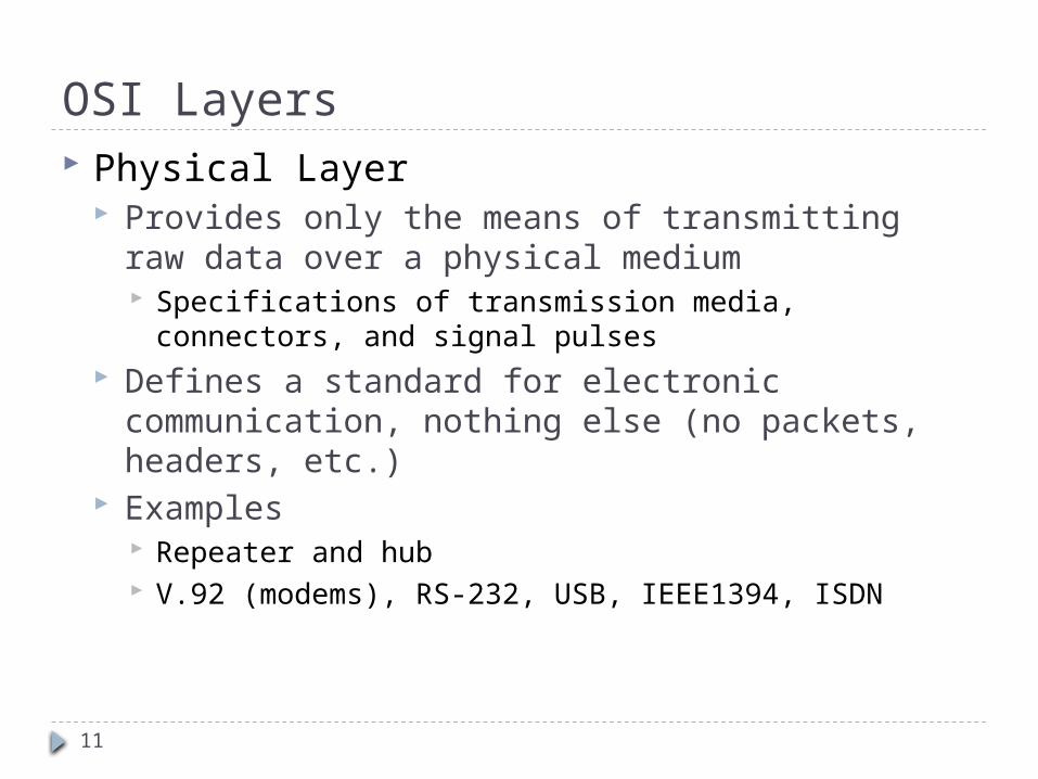
OSI Layers Physical Layer
Provides only the means of transmitting raw data over a physical medium Specifications of transmission media, connectors, and
signal pulses Defines a standard for electronic communication,
nothing else (no packets, headers, etc.) Examples
Repeater and hub V.92 (modems), RS-232, USB, IEEE1394, ISDN

12
Data-Link Layer Specifications of topology and communication
between local systems Packet headers and checksum trailers Packages datagram into frames Detect errors Regulate data flow Maps hardware addresses
Examples Ethernet: works with multiple physical layer specs
(twisted pair cable, fiber) and multiple network layer specs (IPX, IP)
FDDI, T1 Bridges and switches
OSI Layers

13
Network Layer Defines network addresses and how systems on
different network find one another Network segmentation and network address scheme Connectivity over multiple network segments
Examples IP (IPV4/IPV6), IPX, DDP
OSI Layers

14
Transport Layer Responsible for end-to-end message transfer
between processes / applications Assures end-to-end reliability Translates and manages message communication
through subnetworks Ensures data integrity Packet sequencing
Examples IP’s Transmission Control Protocol (TCP), User Datagram
Protocol (UDP), IPX’s Sequence Packet Exchange (SPX), and AppleTalk’s AppleTalk Transaction Protocol (ATP).
OSI Layers

15
OSI Layers Session Layer
Establishing and maintaining a connection between two or more systems Connection negotiation Establishing and maintaining connection Synchronizing dialog
16
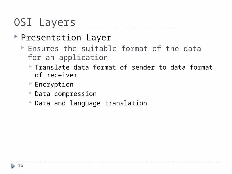
OSI Layers Presentation Layer
Ensures the suitable format of the data for an application Translate data format of sender to data format of
receiver Encryption Data compression Data and language translation
17
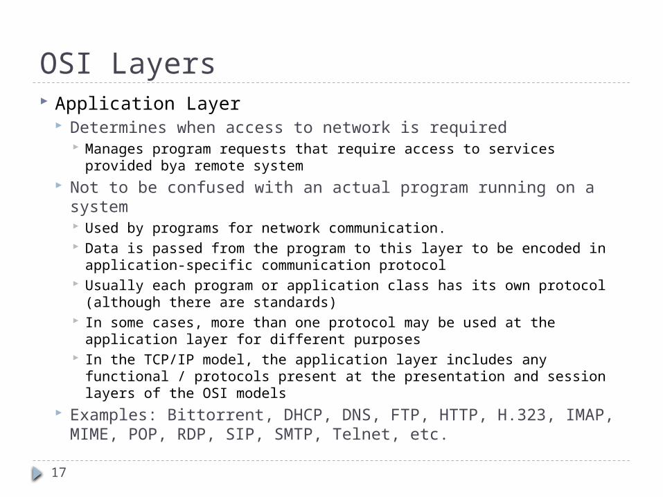
Application Layer Determines when access to network is required
Manages program requests that require access to services provided bya remote system
Not to be confused with an actual program running on a system Used by programs for network communication. Data is passed from the program to this layer to be encoded in
application-specific communication protocol Usually each program or application class has its own protocol
(although there are standards) In some cases, more than one protocol may be used at the application
layer for different purposes In the TCP/IP model, the application layer includes any functional /
protocols present at the presentation and session layers of the OSI models
Examples: Bittorrent, DHCP, DNS, FTP, HTTP, H.323, IMAP, MIME, POP, RDP, SIP, SMTP, Telnet, etc.
OSI Layers

18
How OSI works: sending a remote file request by word processing application Application layer
creates the request to access the file Presentation layer
encrypts if needed Session layer
checks the application that is requesting and the service that is been requested adds information for remote system to correctly handle this request
Transport layer ensures it has a reliable connection starts splitting and sequencing the information if it would not fit in one frame
Network layer adds the source and dest. network addresses
Data-link layer ensures data fit in the limited size adds frame header including MAC addresses and CRC trailer transmits the frame
Physical layer simply passing signal pulses

19
How OSI works: receiving data on remote system
Physical layer Data-link layer
Notices its own MAC address and so should process this request CRC check and if match strips off the header What if CRC check fails?
Network layer Notices its own destination software address
Transport layer Ensures it has all packets in a sequence, What if some packets are missing?
Session layer Verifies if it is from a valid connection
Presentation layer Analyze the frame Perform any translation/decryption needed
Application layer Ensures the correct process receives the request

20
How OSI works: frame structure
21
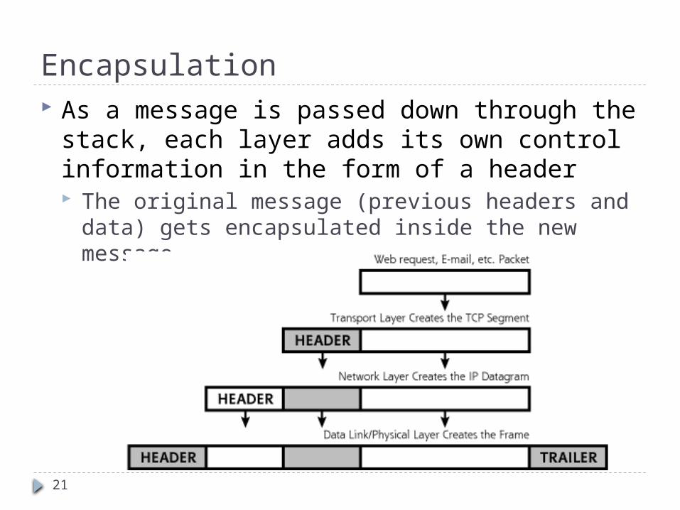
Encapsulation As a message is passed down through the
stack, each layer adds its own control information in the form of a header The original message (previous headers and data)
gets encapsulated inside the new message

22
Networking Protocols For each layer of the stack there are
numerous protocols For each protocol there are security issues related
to these protocols For each security issue there are solutions and
security mechanisms We will focus on a handful of protocols and
study specific problems and solutions

23
Protocols - Ethernet Considered a link-layer protocol by most Ethernet is the most widely used LAN protocol
Competitors –Token ring, FDDI, Frame Relay, PPP, etc. Developed in 1973 at Xerox and is still going
strong Ethernet is designed to operate on small, Local
Area Networks Due to its design characteristics, Ethernet does not
scale well If there are too many hosts (or too much traffic) on an
Ethernet network, the efficiency of that network rapidly declines. (less applicable with switched Ethernet)

24
Protocols - Ethernet Ethernet uses 48 bit hardware (physical) addresses to
deliver packets. Traditional “bus” Ethernet does not direct packets at all Packets are sent out on the shared medium and the
appropriate destination grabs them. (similar to 802.11 today)
With switched Ethernet, packets are sent directly to the destination, and only the destination
In order to time the transmissions, Ethernet uses CSMA/CD Is channel busy?
If not, transmit If yes, wait (for random amount of time) and sense again
Did collision occur? If so, wait (for random amount of time) and then retransmit

25
Network Topologies

26
Network Topologies Ethernet is commonly seen over two different
topologies Switched (Star)
Network is laid out in a star pattern Each computer is connected to the switch Traffic to a node is delivered to that node alone Traffic from that node is delivered only to the switch
Shared (Bus) Network is laid out in a line (or some other shared medium) Each computer “taps into” the line Traffic to and from a node is sent to all nodes
Only the target node is supposed to ”pick up” the packet
Token ring is a shared medium similar to bus Ethernet Shares some of the same security issues

27
Protocols - ARP Address Resolution Protocol Each node maintains an ARP cache – mapping
of MAC/IP addresses (may be dynamic or static)
When an IP packet is received / sent Check ARP cache
If MAC/IP pair is present, forward / send packet If not, issue Broadcast asking for MAC/IP pair Target node (and only target node) should respond with
an ARP reply, which designates a MAC address for the IP address

28
Protocols - IP IP is a network layer protocol used for
delivering data over a packet switched network IP Provides for
Addressing Fragmentation Quality of Service
IP is designed for packet switched networks IP is a stateless protocol IP provides best effort service
Data corruption (except header), out-of-order packet delivery, duplication arrival, dropped/discarded packets
29
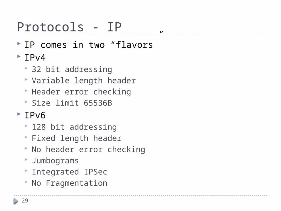
Protocols - IP IP comes in two “flavors” IPv4
32 bit addressing Variable length header Header error checking Size limit 65536B
IPv6 128 bit addressing Fixed length header No header error checking Jumbograms Integrated IPSec No Fragmentation

30
IP Structure (IPv4)

31
IP Structure (IPv6)
32
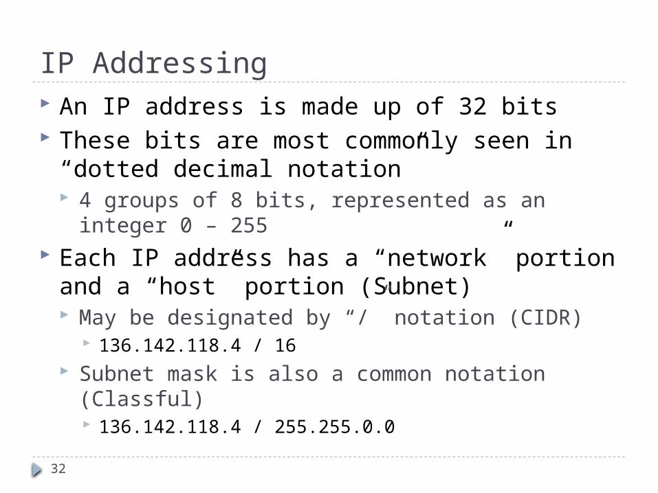
IP Addressing An IP address is made up of 32 bits These bits are most commonly seen in “dotted
decimal notation” 4 groups of 8 bits, represented as an integer 0 –
255 Each IP address has a “network” portion and a
“host” portion (Subnet) May be designated by “/” notation (CIDR)
136.142.118.4 / 16 Subnet mask is also a common notation (Classful)
136.142.118.4 / 255.255.0.0

33
IP Addressing - Classful The original structure of IP addresses Addresses divided in blocks based on octets
Very wasteful of IP Address space Smallest network accommodated 256 hosts, next largest
65536 Classful addressing has been superseded by CIDR
Class Leading BitsClass AClass BClass C
Size of NetworkNumber Bit field
Size of RestBit field
0 7 24 10 14 16 110 21 8
Class D (multicast) 1110Class E (reserved) 1111

34
IP Addressing - CIDR Classless Inter-domain Routing Uses a technique called Variable Length
Subnet Masking Allows for the division of IP address space into
appropriately sized blocks Allows for the aggregation of smaller, separated
subnets into “supernets” CIDR supersedes the classful scheme

35
CIDR Example

36
Special IP Ranges The IP address specification contains several
ranges reserved for special purposes

37
IP Parameters - Example

38
IP Routing Each node on a network has a locally (globally) unique IP address
This IP address uniquely identifies the particular node Combined with the netmask, it allows a machine to determine its
subnet i.e., which machines are logically attached directly to its LAN

39
IP Routing When a node must send an IP packet
First it checks its routing table – Does an explicit route exist?
If no explicit route exists, the machine must determine if the node is on the local subnet If so, ARP is used to determine the MAC address of the
target If the node is not on the local subnet, it is sent to
the local gateway (if applicable) If there is no local gateway, the destination is
deemed “unreachable”
40
OSPF, RIP, ISIS and BGP In order to properly route packets, routers and nodes must
maintain a routing table of some sort The type of routing table and protocol used depends on
several factors “Internal” vs. “External” gateway protocol, size and complexity
of network, type of equipment, etc. RIP is a commonly used “distance vector” algorithm
RIP routers maintain network reachability information in the form of destination / distance metric pairs
OSPF and ISIS are link state protocols Each router computes the shortest path network typology based
on broadcasted routing information BGP is a manually configured routing protocol used at the
“core backbone” of the internet BGP considers other factors like cost and ownership

41
Routing Table

42
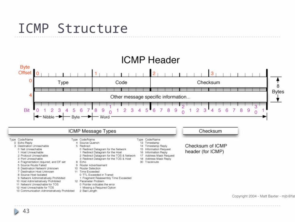
Protocols - ICMP Internet Control Message Protocol (ICMP) is
supposedly a very low-key protocol to answer simple requests It sits below the transport layer and above the IP layer of
the protocol stack No port numbers of any kind - but it has types and codes
in the first two bytes of the header No concept of client or server - effects are mostly internal
to the recipient host No guarantees of delivery
Hosts need not be listening to ICMP messages ICMP messages can be broadcast to hosts Can be a source of information leaks - e.g. host is
unreachable
43
ICMP Structure

44
ICMP Types & CodesTYPE CODE Description
0 0 Echo Reply3 0 Network Unreachable3 1 Host Unreachable3 2 Protocol Unreachable3 3 Port Unreachable3 4
3 5 Source routing failed3 6
3 7 Destination host unknown3 8
3 9
3 10
3 11
3 12 Host unreachable for TOS3 13
3 14 Host precedence violation3 15 Precedence cutoff in effect
Fragmentation needed but no frag. bit set
Destination network unknown
Source host isolated (obsolete)Destination network administratively prohibitedDestination host administratively prohibitedNetwork unreachable for TOS
Communication administratively prohibited by filtering
TYPE CODE Description4 0 Source quench
5 0 Redirect for network5 1 Redirect for host
5 2
5 3 Redirect for TOS and host
8 0 Echo request9 0 Router advertisement
10 0 Route solicitation11 0 TTL equals 0 during transit
11 1
12 0
12 1 Required options missing13 0
1415 0
16 0
17 0 Address mask request
18 0 Address mask reply
Redirect for TOS and network
TTL equals 0 during reassemblyIP header bad (catchall error)
Timestamp request (obsolete)
Timestamp reply (obsolete)Information request (obsolete)Information reply (obsolete)

45
ICMP Types & Codes “ping” transmits ICMP (8,0) and receives ICMP
(0,0) “traceroute” uses ICMP
Sends an ICMP with TTL = 1,2,3,4,... to destination
Each router along the path detects the TTL has expired and responds with an ICMP (11,0) allowing traceroute to determine the route

46
Legitimate ICMP Activity Routers deliver “host unreachable” message
Common when hosts are shut down for maintenance or otherwise
Can be used in reconnaissance information Port unreachable
ICMP can be used to check if a UDP port is open TCP ports reply with a RST/ACK flags
Routers sometime inform you that ICMP traffic is blocked!
Router redirect messages Informs host of a more optimum router
Need to fragment packets because MTU is exceeded TTL expired (time exceeded in transit, e.g. traceroute)

47
Protocols - TCP A transport layer protocol that is carried by IP TCP provides
Reliability TCP ensures that segments make it across the network Segments are checked to make sure they were not corrupted TCP uses ACKs and retransmissions to achieve this
Guaranteed order TCP delivers the packets in the order in which the were sent
Flow control It throttles the rate at which packets are sent if the receiver or
network cannot handle the load Multiplexing
TCP allows many concurrent connections to take place between two end points
This is achieved using ports

48
TCP Segment Structure

49
TCP Segment Structure Source & Destination Ports
Designates the originating machine and process as well as the target machine and process
Sequence Number Track the number of bytes sent / received
Acknowledgement number Designates the next expected sequence number
Flags ACK - indicates its ACK field is valid RST, SYN and FIN are used for connection set up and
tear down PSH - send data to higher layers right away URG - there is some urgent data

50
TCP Flags TCP flags are 6 bits that manage the state of a
TCP connection ACK – indicate that the packet is acknowledging the
receipt of some previous message RST – a reset flag indicates that a connection should
immediately be aborted SYN – Indicates the first packet in a transaction
Essentially requests a connection FIN – Requests a disconnection PSH – push indicates that there is no more data, and
the data in the buffer now should be sent to the application
URG – there is some urgent data in the packet (e.g., ctrl-c)

51
TCP Ports and Processes When two “machines” communicate across a
network, it is actually two processes running on those machines that are communicating
Communicating processes typically have a client side and a server side Two processes on two different hosts that
communicate using sockets A socket is like a door through which messages
are sent and received Interface between the application process and the
transport layer

52
TCP Ports and Processes

53
TCP Ports and Processes TCP identifies a connection based on four
pieces of information Source IP address Source Port number Destination IP address Destination Port number
TCP uses these pieces of information to sort segments and deliver them to the proper process
Port numbers allow TCP to multiplex a single network card / address into a larger number of potential connections

54
Ports and Servers Some machines contain processes which constantly
“listen” on a particular port for incoming connections A Client contacts the server initially for all
communications Server should react to the initial contact – it keeps listening
to the port It has an initial “socket object” to accept connections It creates a new socket dedicated to a particular client after
connection The initial socket object is what we loosely call as an “open”
port It is really a half-open object
Popular standard protocols have assigned (fixed) port numbers Clients are aware of these numbers before they place a call

55
Common Port Numbers
Port Description status
20/TCP Official
21/TCP Official
22/TCP,UDP Official
23/TCP,UDP Official
25/TCP,UDP Official
53/TCP,UDP Official
56/TCP,UDP Route Access Protocol Official
57/TCP MTP, Mail Transfer Protocol
80/TCP Official
81/TCP Official
88/TCP Official
109/TCP POP, Post Office Protocol, version 2
110/TCP Official
143/TCP,UDP Official
161/TCP,UDP Official
179/TCP Official
194/TCP Official
366/TCP,UDP SMTP, Simple Mail Transfer Protocol. ODMR, On-Demand Mail Relay
443/TCP Official
465/TCP Unofficial
520/UDP Official
531/TCP,UDP AOL Instant Messenger, IRC Unofficial
989/TCP,UDP Official
990/TCP,UDP FTP Protocol (control) over TLS/SSL Official
992/TCP,UDP Telnet protocol over TLS/SSL Official
993/TCP Official
995/TCP Official
FTP - data port
FTP - control (command) port
SSH (Secure Shell) - used for secure logins, file transfers (scp, sftp) and port forwarding
Telnet protocol - unencrypted text communications
SMTP - used for e-mail routing between mailservers E-mails
DNS (Domain Name System)
HTTP (HyperText Transfer Protocol) - used for transferring web pages
HTTP Alternate (HyperText Transfer Protocol)
Kerberos - authenticating agent
POP3 (Post Office Protocol version 3) - used for retrieving E-mails
IMAP4 (Internet Message Access Protocol 4) - used for retrieving E-mails
SNMP (Simple Network Management Protocol)
BGP (Border Gateway Protocol)
IRC (Internet Relay Chat)
HTTPS - HTTP Protocol over TLS/SSL (encrypted transmission)
SMTP over SSL
Routing - RIP
FTP Protocol (data) over TLS/SSL
IMAP4 over SSL (encrypted transmission)
POP3 over SSL (encrypted transmission)

56
TCP Connection Management TCP is a stateful protocol Client wants to initiate connection
to server It sends a special TCP segment to
the server with the SYN bit set to 1 Let the initial sequence number be
client_isn This is called a SYN segment
Server receives the SYN segment It allocates buffers and variables to
the connection and replies Reply has SYN = 1, acknowledgment
number = client_isn +1 Sequence number is server_isn This is called a SYNACK segment
Connection is completed This is called the “three way
handshake”

57
TCP Connection Termination Remember, TCP is stateful!!! The graceful method to terminate the connection
is to use the FIN field followed by ACK In this case, either the client or the server will first
send a TCP segment with the FIN bit set The receiving host will ACK the FIN This process closes half the connection - it has to be
repeated by the receiving host The abrupt method of closing the TCP connection
is for either the client or the server to send an RST (reset) segment This aborts the TCP connection and no further
communications take place between the hosts

58
Sequence Numbers in TCP Sequence and acknowledgment numbers are
very important in TCP for reliable data transfer The sequence number of a TCP segment tells the
receiver how many bytes of data has been sent Example: the first TCP segment carries 1000 bytes of
data and the sequence number is 235, the next TCP segment will have a sequence number 1235
The acknowledgment number tells the recipient what is the next expected byte number Example: the server receives 1000 bytes from the TCP
segment with sequence number 235 - it has received bytes numbered 235 through 1234. So it sets the ack number to be 1235

59
Sequence Numbers in TCP Sequence number (inadvertently) plays a role in
security If a packet with an improper sequence number is received,
it is dropped TCP assumes that some error has been made during the
transmission and requests a retransmit of the missing packet This make the job of a hacker trying to forge packets
harder To inject packets into an existing connection he or she
must either be able to actively observe the packets in an exchange between
two parties be able to guess what the current sequence number of a session
is For this reason, the truly random generation of sequence number
is important

60
Protocols – UDP Unlike TCP, UDP is a stateless protocol
UDP has no concept of a “connection” UDP requires no initialization or finalization
UDP identifies segments with using the source address and port number
The only service UDP provides is multiplexing UDP benefits from
Lightweight nature of the protocol – little overhead Lack of redundancy or unneeded function
Application layer provides whatever services are necessary
Often used for time sensitive or custom designed protocols

61
UDP Segment Structure

62
TCP vs. UDP TCP
Connection Oriented – setup required between sending and receiving processes
Reliable transport – between sending and receiving process
Flow control – sender won't overwhelm receiver
Congestion control – throttle sender when network overloaded
Multiplexing – a client and server can communicate over multiple connections
does not provide: timing, minimum bandwidth guarantees
UDP Unreliable data
transfer between sending and receiving process
Multiplexing does not provide:
connection setup, reliability, flow control, congestion control, timing, or bandwidth guarantees
63
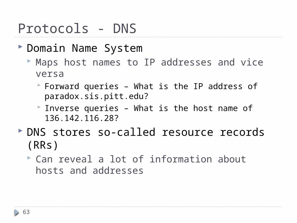
Protocols - DNS Domain Name System
Maps host names to IP addresses and vice versa Forward queries – What is the IP address of
paradox.sis.pitt.edu? Inverse queries – What is the host name of
136.142.116.28?
DNS stores so-called resource records (RRs) Can reveal a lot of information about hosts and
addresses

64
Protocols - DNS Many protocols employ DNS to translate user
supplied names into IP addresses HTTP, FTP, SMTP, etc. all use DNS to resolve
names DNS may add delay to the communications
process DNS may also be a single point of failure
DNS is an application level protocol, but it is typically not used directly by the user
DNS queries and responses are on port 53 using UDP TCP is used for zone transfers

65
Zone Transfers Zone
Name spaces are divided into zones based on separating “periods” in the name
Example: sis.pitt.edu is a zone Each zone maintains primary and secondary
name servers Secondary servers periodically poll primary
servers to obtain zone data If data has changed, a zone transfer is initiated
that downloads the entire database

66
Protocols - DNS In addition to address mapping, DNS provides
Host Aliasing (e.g. paradox.sis.pitt.edu can have two aliases - sis.pitt.edu and www2.sis.pitt.edu)
Mail Server Aliasing (e.g. [email protected] has to go to mail.sis.pitt.edu)
Load Distribution (e.g. many sites use replicated web servers each running on a different end-system host) DNS responds with the entire set of hosts, but rotates
the order periodically

67
Resource Records Resource records (RRs) store the hostname to
IP address mapping Each RR has four fields
[Name, Value, Type, TTL] Many different types TTL specifies how long the RR is valid

68
Name Servers Local Name Servers
Each ISP has its own name servers - all local machines contact the local name server first
Local translations are fast, simple and easy to implement
Root Name Servers Countable numbers worldwide (13) Local servers contact the root server if they cannot
resolve a name Authoritative Name Servers
Root servers direct local servers to an authoritative name server that has the information related to a host
Maintain authoritative data for a zone
69
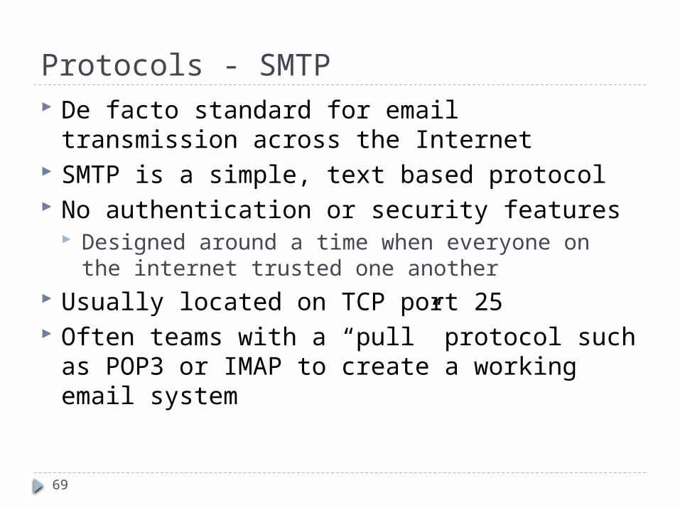
Protocols - SMTP De facto standard for email transmission
across the Internet SMTP is a simple, text based protocol No authentication or security features
Designed around a time when everyone on the internet trusted one another
Usually located on TCP port 25 Often teams with a “pull” protocol such as
POP3 or IMAP to create a working email system

70
SMTP Operation
71
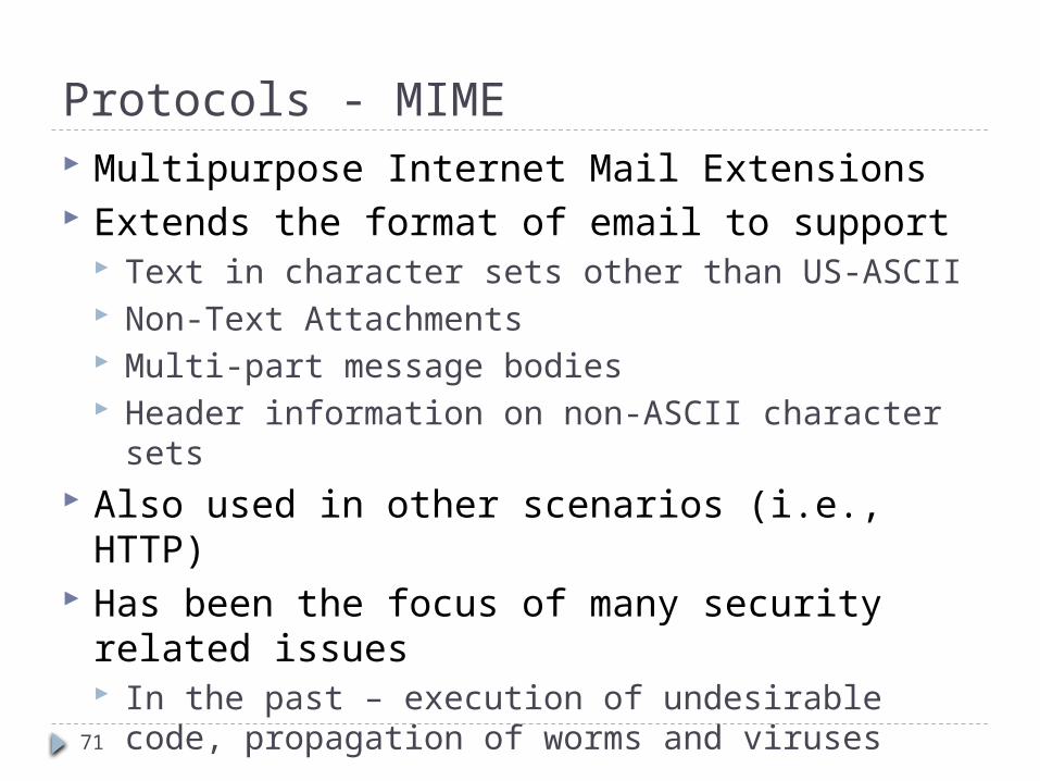
Protocols - MIME Multipurpose Internet Mail Extensions Extends the format of email to support
Text in character sets other than US-ASCII Non-Text Attachments Multi-part message bodies Header information on non-ASCII character sets
Also used in other scenarios (i.e., HTTP) Has been the focus of many security related
issues In the past – execution of undesirable code,
propagation of worms and viruses
72
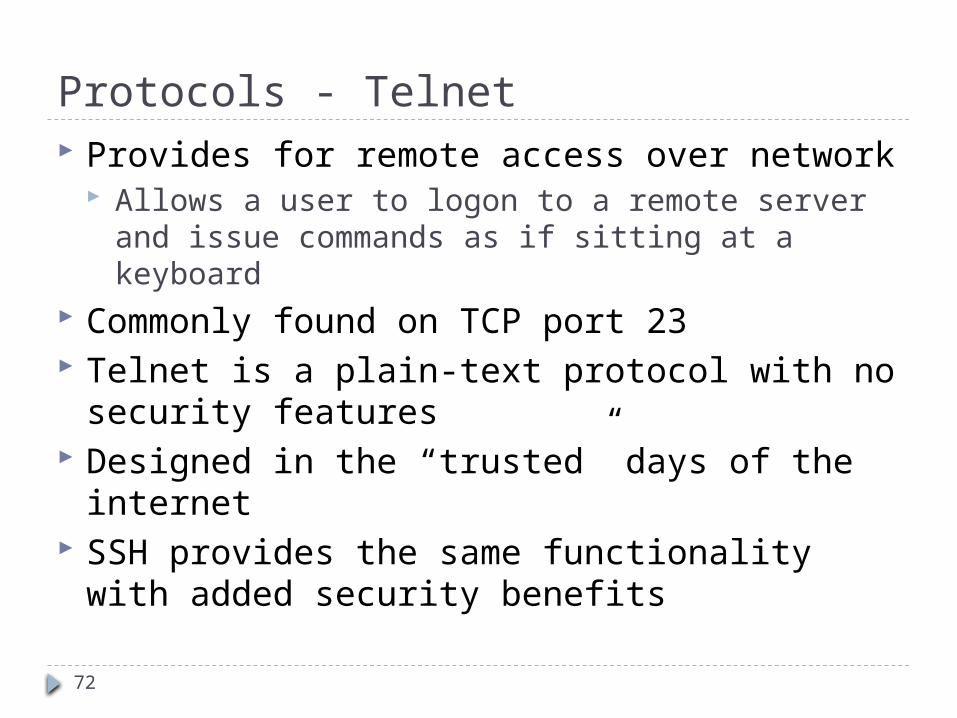
Protocols - Telnet Provides for remote access over network
Allows a user to logon to a remote server and issue commands as if sitting at a keyboard
Commonly found on TCP port 23 Telnet is a plain-text protocol with no security
features Designed in the “trusted” days of the internet SSH provides the same functionality with
added security benefits

73
Protocols – SSH Secure Shell – Usually operates on TCP port 22 Allows for data to be exchanged over a secure
channel Provides for confidentiality, integrity and
authentication through encryption protocols Based on the popular OpenSSL encryption suite
SSH is commonly used for remote login and administration (similar to telnet)
Virtually ANY protocol can be tunneled through SSH X11, FTP (SFTP), TCP, etc. This is both a good and bad thing
74
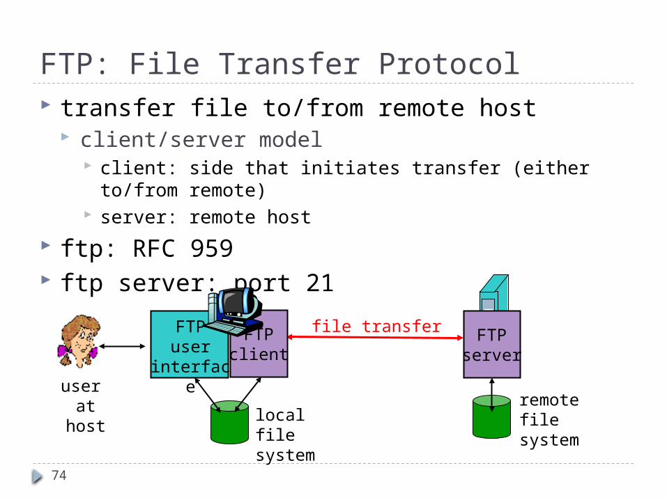
FTP: File Transfer Protocol transfer file to/from remote host
client/server model client: side that initiates transfer (either to/from remote) server: remote host
ftp: RFC 959 ftp server: port 21
file transfer FTPserver
FTPuser
interface
FTPclient
local filesystem
remote filesystem
user at host
75
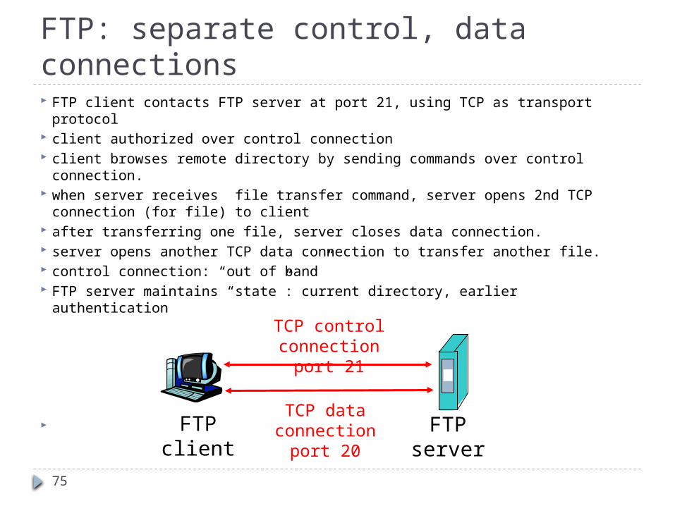
FTP: separate control, data connections FTP client contacts FTP server at port 21, using TCP as transport
protocol client authorized over control connection client browses remote directory by sending commands over control
connection. when server receives file transfer command, server opens 2nd TCP
connection (for file) to client after transferring one file, server closes data connection. server opens another TCP data connection to transfer another file. control connection: “out of band” FTP server maintains “state”: current directory, earlier authentication
FTPclient
FTPserver
TCP control connectionport 21
TCP data connectionport 20

76
FTP is still commonly used on the internet today to facilitate easy file transfer.
Uses two channels – Control and Data FTP can operate in one of two modes
Active FTP client opens a random port > 1023 Client sends the PORT command to the server, telling it which port
to connect on Data is transferred on this new “data” channel
Passive FTP server opens a random port Sends the PASV command to the FTP client, along with the server IP
address and port number to connect to (Server can be different) Client connects to specified machine for download.
Both modes may be difficult to get through a firewall
FTP
77
Protocols – FTP, TFTP, SFTP FTP is a simple protocol designed to transmit text and
binary files Usually operates using TCP ports 20 and 21
Plain FTP has been the subject of many security issues Like telnet, FTP is a plain text protocol FTP is considered insecure and should be avoided if possible
SFTP: Secure FTP
The FTP protocol tunneled over SSH Has some problems due to the two channel nature of FTP
Trivial file transfer protocol Has the same functionality as FTP, but differs in implementation
Both share the same security benefits as SSH SFTP should be used in place of FTP whenever possible
78
Protocols – HTTP and HTTPS HTTP is the common WWW protocol that
allows us to “browse” the internet Operates on top of TCP Also a plain-text, insecure protocol HTTP, like telnet and FTP, has been the subject of
many security issues and vulnerabilities Due to the insecure nature of HTTP, but the
necessity of conducting secure business online, HTTPS was conceived HTTPS is the HTTP protocol secured using SSL
Considered generally secure