review of damages prediction in a composite material at
TRANSCRIPT
See discussions, stats, and author profiles for this publication at: https://www.researchgate.net/publication/337946857
Review of damages prediction in a composite material at low velocity impact
Article · January 2019
DOI: 10.30574/gjeta.2019.1.1.0007
CITATIONS
0READS
21
3 authors, including:
Some of the authors of this publication are also working on these related projects:
characterisation of defect in composite material View project
Prediction of the evolution of an impact on a composite plate View project
Fatima Khathyri
National School of Applied Sciences Oujda
7 PUBLICATIONS 5 CITATIONS
SEE PROFILE
All content following this page was uploaded by Fatima Khathyri on 16 December 2019.
The user has requested enhancement of the downloaded file.

Global Journal of Engineering and Technology Advances, 2019, 01(01), 027–042
Global Journal of Engineering and Technology Advances Cross Ref DOI: 10.30574/gjeta
Journal homepage: http://www.gjeta.com
Corresponding author E-mail address: [email protected]
Copyright © 2019 Author(s) retain the copyright of this article. This article is published under the terms of the Creative Commons Attribution Liscense 4.0.
(REV I EW AR T I CL E)
Review of damages prediction in a composite material at low velocity impact
Khathyri Fatima 1, *, ElkiheL Bachir 1 and Delaunois Fabienne 2
1 Laboratory of Industrial Engineering, Maintenance and Mechanical Production, ENSAO, Oujda, Morocco. 2 Laboratory of Metallurgy, University of Mons, Metallurgy Service, Mons, Belgium.
Publication history: Received on 29 October 2019; revised on 29 November 2019; accepted on 05 December 2019
Article DOI: https://doi.org/10.30574/gjeta.2019.1.1.0007
Abstract
The numerical prediction of composite material damages remains a strong tool that develops day by day. Several numerical models have been developed in the literature for simulating the progressive damage. In this paper the most used low velocity impacts numerical methods available in the literature are reviewed. First the various damage mechanisms of laminated composite materials are described. Then, different damages modelling are presented, from the onset to the final rupture. Finally, some results of the finite element model (FEM) are reported.
Keywords: Analytical prediction; Composite material; Low velocity impact; FEM; Damage mechanisms
1. Introduction
Over the past decades, composite materials have been used in many industrial applications such as the aerospace, automobile and naval applications, etc. This material, are well known for their interesting characteristics, like their high strength and stiffness to weight ratios, good fatigue performance, important vibration damping and excellent corrosion resistance. For all this reason, the aeronautical engineering goes to replace metallic materials by composites in order to save energy. Metallic materials and their associated plasticity is a well-researched area for many years. Yet, many things have to be learnt about composite behavior where the damage prediction remains very difficult [1].
Unfortunately, during a manufacturing (M. Hassan and al. [2] review the manufacturing defects in aircraft composite structure in their work) operation or use, the composite could be significantly damaged, due to their complexity structure. So, a variety of the failure modes and damages are likely occurring in the lifetime of composite materials compared with the metallic materials. Furthermore, the damage developed internally of the composite structure can drastically reduce his performance. Among this damage, the low-velocity impact is the one of the most critical damage in laminated composite structures, it represents around about 80% in service damages [3]. It can reduce strength and stiffness significantly without any visible damage at the surface [4, 5]. Thus, it is important to study the low velocity impact behavior to understand the progressive damage may produce in composite laminate structures.
Therefore, it is essential to inspect this component during their life in order to assess the presence of defects, also to characterize them. To this effect, numerous non-destructive techniques (NDT) are available such as ultrasound [6, 7], active thermography [8], x-ray radiography [9], shearography and acoustic emission [10]. They represent a good solution to investigate the composite components without damaging them. As well as, the inspection of components can be used during production, either during use or as part of maintenance. On the other hand, the numerical prediction of the residual resistance after impact is considered one of the most efficient tools to predict in a realistic way the effect of an impact and to be able to predict the damage of the structures, then their residual behavior. Hence, the numerical prediction after impact will make it possible to reduce the masses and to avoid expensive tests.
Khathyri et al. / Global Journal of Engineering and Technology Advances, 2019, 01(01), 027–042
28
Several numbers of predictive methods have been proposed in the literature to model the onset and the propagation of different modes of damage in composite materials [11, 12]. The finite element model (FEM) represents the preferred methods by researchers, in order to study the impact damage issues of composite laminates. It is a desirable approach to accurately predict and in a relatively short time the complex internal damage pattern, which can be formed in composite laminates. Indeed, different commercial finite element codes have been used for impact behavior simulation in recent years such as ABAQUS/EXPLICIT [13], LS-DYNA [14] among others.
The scope of this paper is to review the numerical prediction of damage in composite structures using the FEM. Starting by study of defects may appear in the composite material as well as the causes of their appearance. The impact damage at low velocity represents the main cause of the creation of the damages in this structure. So, it will be the main focus of this work. For this reason, it's important to understand his damage mechanisms, in the aim to model the damage development of composite laminates in the design.
2. Defects of composite materials
Structures based on composite as any material are subjected to various mechanisms degrading their mechanical performance. This section is intended to describe the various mechanisms of damage to laminated composites.
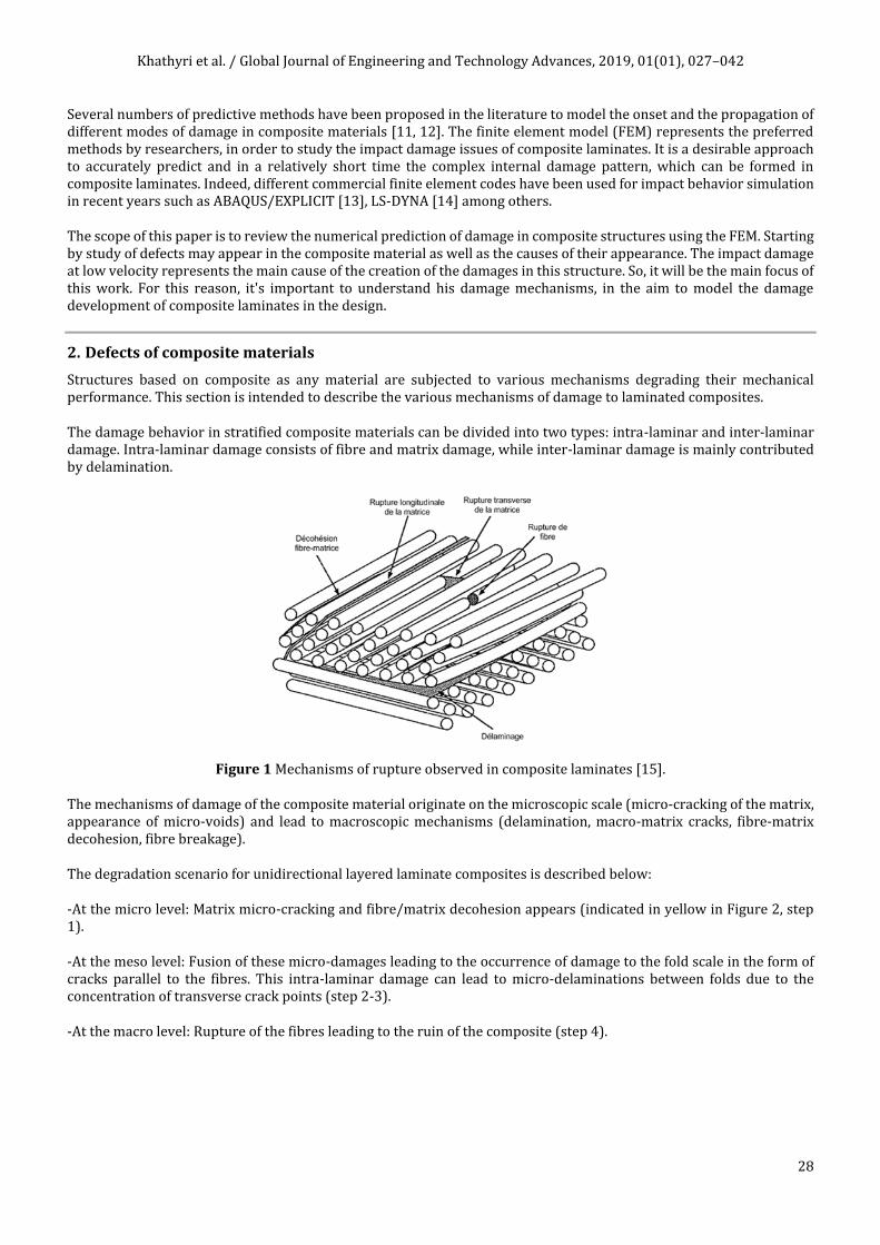
The damage behavior in stratified composite materials can be divided into two types: intra-laminar and inter-laminar damage. Intra-laminar damage consists of fibre and matrix damage, while inter-laminar damage is mainly contributed by delamination.
Figure 1 Mechanisms of rupture observed in composite laminates [15].
The mechanisms of damage of the composite material originate on the microscopic scale (micro-cracking of the matrix, appearance of micro-voids) and lead to macroscopic mechanisms (delamination, macro-matrix cracks, fibre-matrix decohesion, fibre breakage).
The degradation scenario for unidirectional layered laminate composites is described below:
-At the micro level: Matrix micro-cracking and fibre/matrix decohesion appears (indicated in yellow in Figure 2, step 1).
-At the meso level: Fusion of these micro-damages leading to the occurrence of damage to the fold scale in the form of cracks parallel to the fibres. This intra-laminar damage can lead to micro-delaminations between folds due to the concentration of transverse crack points (step 2-3).
-At the macro level: Rupture of the fibres leading to the ruin of the composite (step 4).

Khathyri et al. / Global Journal of Engineering and Technology Advances, 2019, 01(01), 027–042
29
Figure 2 Damage scenario during loading of a laminate composite [16].
The development of these mechanisms of damage depends on the nature of the materials and also of the mechanical stresses imposed.
These different modes of damages are created by various causes such as: impact and fatigue, which represent the main causes meeting in the composite structures.
2.1. Impact
The composite material is likely to be subject to the many impacts in their life time. For this reason, several studies have been focused on the investigation of the impact and their consequence on composite materials. So, in this part we try to understand the impact behavior.
The impact is generally classified by their velocity in different categories: low, moderate, high and very high velocity [17].
Table 1 Description of the different impact categories identified in the literature. [18]
Category Velocity (m/s) Mass (g) Impact energy (J) Application domain
Test bench used
Low velocity <10 50-30000 1-200 Transport Drooping weight
Moderate velocity
50-200 1-200
1-4000 Transport Cannon, Hopkinson bars.
High velocity
Ballistic
200-500
200-600
5-500
5-20
100-20000
100-500
Transport
military protection
Cannon, Hopkinson bars.
Shooting range, cannon.
very high velocity
1000-5000 0.001 About.100 Aerospace Cannon.
These levels of velocity presented in the table 1 are the levels found in different studies. Considering the high velocity impact, most publications focus on the ballistic case, which can be considered as a sub-domain of high velocity impacts [19]. It is characterized by penetration into the component or its perforation, accompanied by fiber breaks. So, the process of penetration (fig.3) starts by the shear of the fiber followed by tensile fiber failure and ends with the delamination [20]. This scenario may explained by the speed of the projectile. At the beginning of the impact when the

Khathyri et al. / Global Journal of Engineering and Technology Advances, 2019, 01(01), 027–042
30
projectile velocity is still very high the delaminations do not have time to propagate and leading to very localized damage. So, from the figure 3, it can be seen clearly that as the projectile gradually decelerates, the delaminated area gradually increases in the thickness of the specimen [21].
Figure 3 Failure modes in ballistically penetrated laminates [19].
Midway between the low and high velocity categories is the category of impacts at moderate velocity or so-called intermediate. Finally, the category of low velocity impact represents the more difficult one to study due to the invisible damages produced after the impact event which can reduce drastically the performances of material [22]. Otherwise, Garnier [23] represented in his work another point of view of Abrate [20], which considers that all dynamic stresses less than 100 (m/s) are considered as low velocity impacts.
Therefore, the low velocity impact is chosen to be studied in this work. So, it’s necessary to understand the impact phenomenon and the damage mechanisms of the chosen category.
2.2. The damage mechanisms of a low velocity and low energy impact
The heterogeneity and the anisotropic nature of the composite materials involve many forms of degradations like: matrix cracking, delamination and fiber breakage [24]. These last can developed inside, the material thickness without any perception on the impacted side. Each failure mechanism absorbs a certain proportion of the energy and was responsible for the deceleration of the energy and then the deceleration of the projectile.
Figure 4 Schematic representation shows typical modes of damage in composite laminates [25].
The typical form of internal impact damage to laminated composites is conical in the thickness, with the damaged area growing from the front to the back as shown in the figure 4. The degradation start with the matrix crack, which is separated into two types: tensile cracks (fig.5.a) and shear cracks (fig.5.b).
Khathyri et al. / Global Journal of Engineering and Technology Advances, 2019, 01(01), 027–042
31
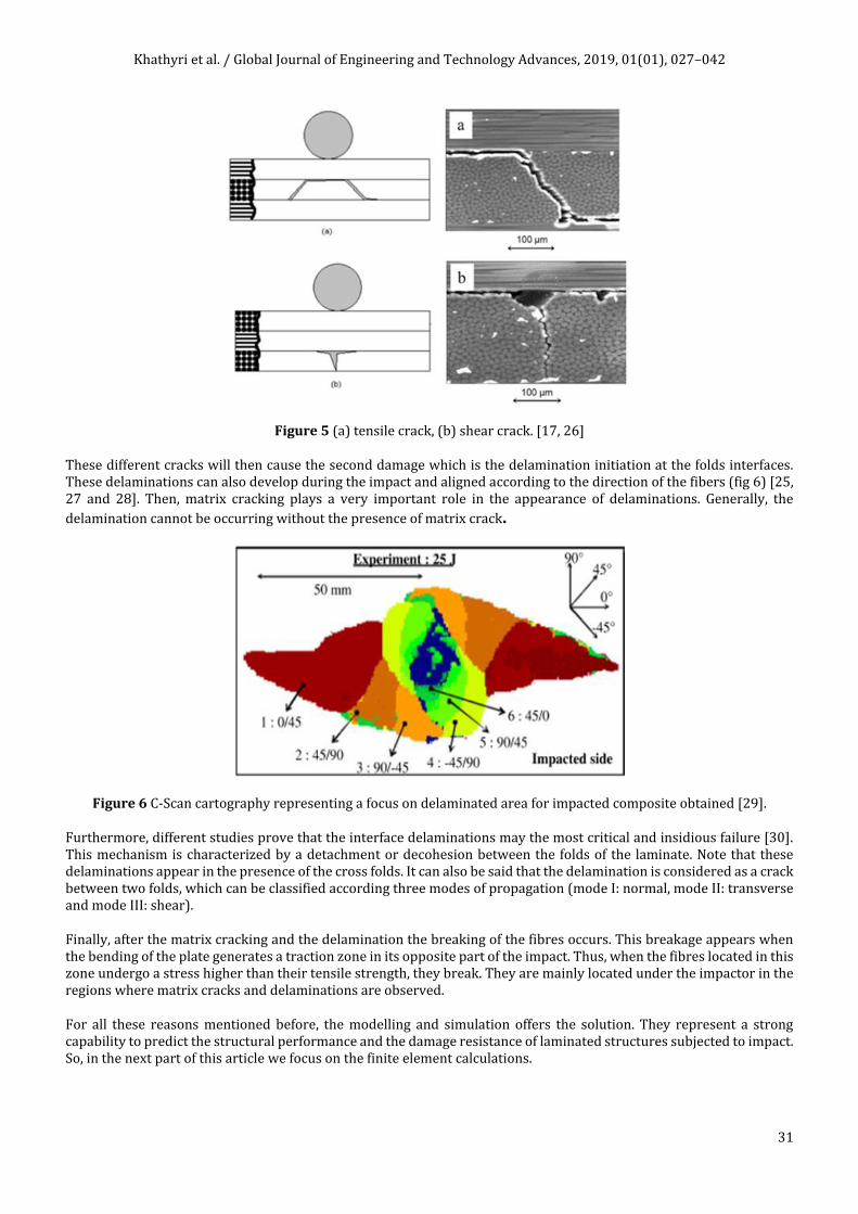
Figure 5 (a) tensile crack, (b) shear crack. [17, 26]
These different cracks will then cause the second damage which is the delamination initiation at the folds interfaces. These delaminations can also develop during the impact and aligned according to the direction of the fibers (fig 6) [25, 27 and 28]. Then, matrix cracking plays a very important role in the appearance of delaminations. Generally, the
delamination cannot be occurring without the presence of matrix crack.
Figure 6 C-Scan cartography representing a focus on delaminated area for impacted composite obtained [29].
Furthermore, different studies prove that the interface delaminations may the most critical and insidious failure [30]. This mechanism is characterized by a detachment or decohesion between the folds of the laminate. Note that these delaminations appear in the presence of the cross folds. It can also be said that the delamination is considered as a crack between two folds, which can be classified according three modes of propagation (mode I: normal, mode II: transverse and mode III: shear).
Finally, after the matrix cracking and the delamination the breaking of the fibres occurs. This breakage appears when the bending of the plate generates a traction zone in its opposite part of the impact. Thus, when the fibres located in this zone undergo a stress higher than their tensile strength, they break. They are mainly located under the impactor in the regions where matrix cracks and delaminations are observed.
For all these reasons mentioned before, the modelling and simulation offers the solution. They represent a strong capability to predict the structural performance and the damage resistance of laminated structures subjected to impact. So, in the next part of this article we focus on the finite element calculations.

Khathyri et al. / Global Journal of Engineering and Technology Advances, 2019, 01(01), 027–042
32
3. Damage modelling onset and evolution
Since the 1970s, finite element methods have known an important development. Such as, the remarkable evolution of impact analysis methods, which went from a simple analytical model (spring mass model at a 1D) to high-fidelity finite element approaches (Fiber-matrix model in 3D). These methods offer the possibility of predicting the onset and the propagation of damage.
Figure 7 Summary of impact analysis methods. [31]
Several numerical models have been developed in the literature for simulating the progressive damage in laminated composite such as transverse cracking, delamination and fiber breakage. As it has been reported before that the damages are classified according to two categories: intra-laminar and inter-laminar damage. So it is necessary for
modelling the onset and the propagation of each category.
3.1. Intra-laminar damage
3.1.1. Damage criteria
The subject is to predict the damage behaviors of composite at low velocity. For this reason the failure criteria are considered as conditions for prediction of the occurrence of material damage. Mathematically, it refers to equations that predict the states of stress and strain at the onset stage of damage. Several models have been proposed to simulate the initiation criteria, such as S. W. Tsai and E. M. Wu [32], C. T. Sun et al. [33] and A. Puck and H. Schürmann [12]. Murugesan and Rajamohan [34], review the latest developments in the investigation of progressive ply failure of laminated composite structures in their work.
The most commonly used initiation criterion is the Hashin & Rotem criterion [11, 35]. It is used to predict four failure criteria in the matrix and fiber, under both tension and compression modes:
Khathyri et al. / Global Journal of Engineering and Technology Advances, 2019, 01(01), 027–042
33
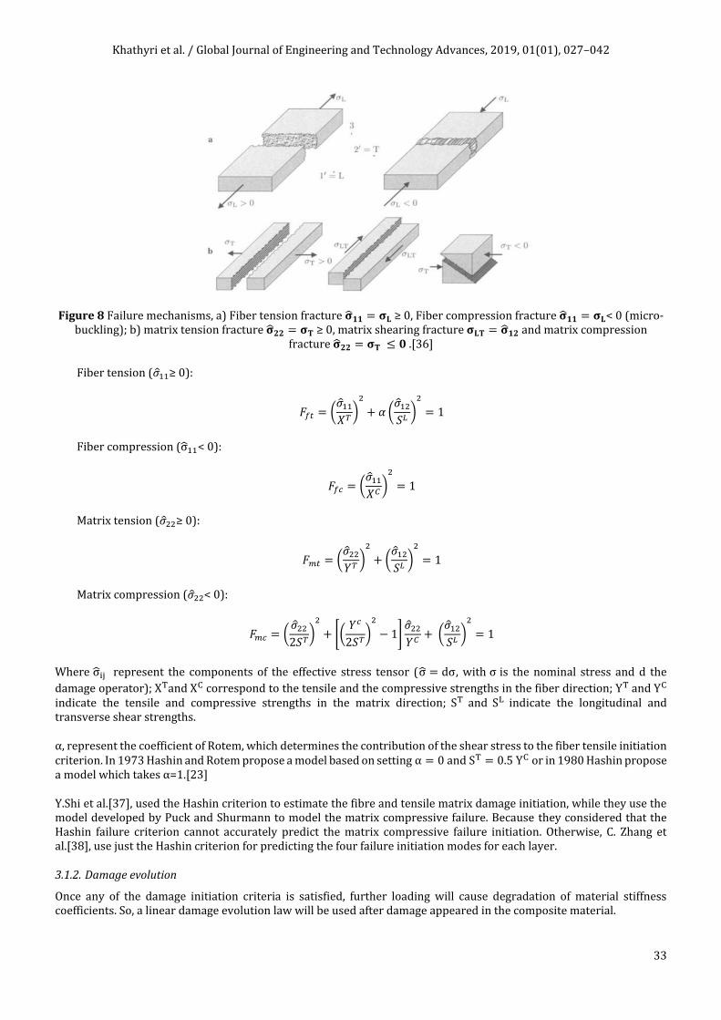
Figure 8 Failure mechanisms, a) Fiber tension fracture ��𝟏𝟏 = 𝛔𝐋 ≥ 0, Fiber compression fracture ��𝟏𝟏 = 𝛔𝐋< 0 (micro-buckling); b) matrix tension fracture ��𝟐𝟐 = 𝛔𝐓 ≥ 0, matrix shearing fracture 𝛔𝐋𝐓 = ��𝟏𝟐 and matrix compression
fracture ��𝟐𝟐 = 𝛔𝐓 ≤ 𝟎 .[36]
Fiber tension (��11≥ 0):
𝐹𝑓𝑡 = (��11
𝑋𝑇)
2
+ 𝛼 (��12
𝑆𝐿)
2
= 1
Fiber compression (σ11< 0):
𝐹𝑓𝑐 = (��11
𝑋𝐶)
2
= 1
Matrix tension (��22≥ 0):
𝐹𝑚𝑡 = (��22
𝑌𝑇)
2
+ (��12
𝑆𝐿)
2
= 1
Matrix compression (��22< 0):
𝐹𝑚𝑐 = (��22
2𝑆𝑇)
2
+ [(𝑌𝑐
2𝑆𝑇)
2
− 1]��22
𝑌𝐶+ (
��12
𝑆𝐿)
2
= 1
Where σij represent the components of the effective stress tensor (σ = dσ, with σ is the nominal stress and d the
damage operator); XTand XC correspond to the tensile and the compressive strengths in the fiber direction; YT and YC indicate the tensile and compressive strengths in the matrix direction; ST and SL indicate the longitudinal and transverse shear strengths.
α, represent the coefficient of Rotem, which determines the contribution of the shear stress to the fiber tensile initiation criterion. In 1973 Hashin and Rotem propose a model based on setting α = 0 and ST = 0.5 YC or in 1980 Hashin propose a model which takes α=1.[23]
Y.Shi et al.[37], used the Hashin criterion to estimate the fibre and tensile matrix damage initiation, while they use the model developed by Puck and Shurmann to model the matrix compressive failure. Because they considered that the Hashin failure criterion cannot accurately predict the matrix compressive failure initiation. Otherwise, C. Zhang et al.[38], use just the Hashin criterion for predicting the four failure initiation modes for each layer.
3.1.2. Damage evolution
Once any of the damage initiation criteria is satisfied, further loading will cause degradation of material stiffness coefficients. So, a linear damage evolution law will be used after damage appeared in the composite material.

Khathyri et al. / Global Journal of Engineering and Technology Advances, 2019, 01(01), 027–042
34
Figure 9 The evolution law of fiber tensile damage.
The figure 9 represents the progressive damage bilinear model. It is composed of a first ascending portion translating the reversibility from A to B (small loading) the material is undamaged before B. Once the permissible intra-laminar stress is reached (at the point B the initiation of damage start (d=0)), the stiffness of the interface are degraded until rupture of the contact and thus propagation of damage from B to D. This second portion is called the evolution law. As the load increases, the energy starts to dissipate by unloading in the region B–D. At point C the critical fracture energy is dissipated, where the area under the bi-linear graph is equal to the material fracture toughness Gft, the crack deemed to be formed. In this case the point unloads elastically towards the origin with a reduced stiffness. Reloading will follow this path again until it reaches point C and then proceed until complete failure at point D (d=1).
d, represent the damage indicator evolving from 0 to 1. It monitors the evolution of damage for each mode in fiber and matrix which can be illustrated in the form:
𝑑𝑖 =𝜀11
𝑡 (𝜀11−𝜀110 )
𝜀11(𝜀11𝑡 −𝜀11
0 ) ; 휀11
0 ≤ 휀11 ≤ 휀11𝑡 𝑖 ∈ (𝑓𝑐, 𝑓𝑡, 𝑚𝑐, 𝑚𝑡)
Where,
ε110 , represents the initial normal strain corresponding to the failure initiation strain either in tension or compression;
ε11t , correspond to the maximum strain when the stresses are equal to zero and fiber (or matrix) is completely damaged in
tension or compression;
Gft, is fracture energy.
3.2. Inter-laminar damage
To predicting delamination two promising methods are available: virtual crack closure technique (VCCT) and cohesive zone methods (CZM). The VCCT was proposed by Rybicki and Kannien [39]. Ronald Krueger [40] was overview it in his work. This method is based on the hypothesis of a pre-existing crack in the material and on the assumption that the energy released during delamination propagation equals to the energy needed to close the crack back to its original position. However the VCCT method represents some difficulties in the usage as cited in several works. To overcome the failures of the preceding method the researchers use the cohesive zone model such as its found in the works of A. Turon et al.[41], A. Riccio et al.[42] and O. T. Topac et al.[43]…etc.
The cohesive zone models have firstly proposed by Dugdale [44] and Barenblatt [45] and developed after by several authors, which are summarized in the work of Vandellos [46]. It has the advantage of being able to describe both the initiation (by the use of strength-based criteria) and the propagation of delamination (using the fracture mechanics energy criteria) without a priori hypothesis about the crack. Thus, the CZM is based on the traction-separation law, which governs the separation displacement of the nodes (initially superimposed) on two adjacent surfaces.
3.2.1. Damage criterion
At low velocity the dominate failure mode in the composite laminate is the inter-laminar damage which is called delamination. So, like it mentioned before the use of the cohesive element help to capture the onset and propagation of delamination between layers of composite under the mixed-modes loading condition.

Khathyri et al. / Global Journal of Engineering and Technology Advances, 2019, 01(01), 027–042
35
The initiation of delamination can be predicted by the quadratic failure criterion [47, 48] using cohesive elements. So, the damage is assumed to initiate when the function presented below reaches one:
(⟨𝜏3⟩
𝑁)
2
+ (𝜏2
𝑆)
2
+ (𝜏1
𝑇)
2
= 1 ;
Which τ2 and τ1 are the inter-laminar shear stress, τ3 is the inter-laminar normal stress, and S, T and N are the inter-laminar strength allowable.
Using the penalty stiffness the traction-relative displacement law can be written as:
𝜏 = (
𝜏3
𝜏2
𝜏1
) = [
𝑘3
𝑘2
𝑘1
] (
𝛿3
𝛿2
𝛿1
) ;
Where 2, 1 and 3 denote the three orthogonal directions; 3 denote the trough-thickness direction and correspond to the mode I failure; the 2 and 1 directions correspond to the Mode II and III failures (the shear failures parallel and transverse to the fiber direction, respectively); τ3 is the out-of-plane normal stress; τ2 and τ1 are the transverse shear stresses;δ3,δ2, δ1 and k3, k2, k1 are the corresponding relative displacements and penalty stiffnesses, respectively.
The penalty stiffnesses are defined as:
𝑘𝑖 = {𝑘𝑖
0
(1 − 𝑑𝑖)𝑘𝑖0
0
𝛿𝑖 ≤ 𝛿𝑖0
𝛿𝑖0 ≤ 𝛿𝑖 ≤ 𝛿𝑖
𝑓
𝛿𝑖 ≥ 𝛿𝑖𝑓
; 𝑖 = 3,2,1
ki0, indicate the initial penalty stiffness; δi
0 and δif correspond to the relative displacement of each single mode loading
at delamination initiation and the point where delamination is completely formed; di is the damage operator.
3.3. Damage evolution
As previously mentioned, once the damage initiation law is reached the material stiffness is gradually degraded. For monitoring the damage evolution in a linear reduction process the damage variable d was used, which range from the value of 0 (undamaged interface) to the value of 1 (complete decohesion of the interface).
𝑑𝑖 =𝛿𝑖
𝑓(𝛿𝑖 − 𝛿𝑖0)
𝛿𝑖(𝛿𝑖𝑓
− 𝛿𝑖0)
In order to describe the evolution of damage under mixed modes separations across the interface, effective separation δm is
introduced:
𝛿𝑚 = √⟨𝛿3⟩ + 𝛿1 + 𝛿2
Whereδ3,δ1,δ2 are the interfacial separations in the normal and two tangential directions, respectively. With⟨∙⟩ = (∙ +|∙|)/2 ,
represent the Macaulay operator.
The damage evolution in this case meaning in the inter-laminar damage is similar whit the law discussed above of intra-laminar
damage. So it can be seen clearly in the figure 10 that before delamination appeared (δi < δi0), the interaction was considered
to have a linear behavior.
When the damage criterion was satisfied (δi = δi0; d = 0), the cohesive stiffness degrades linearly up to the complete
decohesion of the interface (δi = δif; d = 1).

Khathyri et al. / Global Journal of Engineering and Technology Advances, 2019, 01(01), 027–042
36
Figure 10 Traction-separation law for cohesive material [48].
Several propagation criteria have been proposed in the literature for laminated carbon/epoxy to model delamination propagation under mixed-mode loading. Among all of them we found the power law criteria [49] and B-K the most useful. This criterion allows calculating the critical threshold of propagation as a function of the mixed modes.
The propagation of delamination occurs when the energy restitution rate G reaches the critical threshold GC (fracture energy of delamination with mixed modes, i.e.GC = GI + GII + GIII):
𝐺 ≥ 𝐺𝐶
The general form of the power law is:
(𝐺𝐼
𝐺𝐼𝐶)
2
+ (𝐺𝐼𝐼
𝐺𝐼𝐼𝐶)
2
+ (𝐺𝐼𝐼𝐼
𝐺𝐼𝐼𝐼𝐶)
2
= 1 ;
Where GI, GII,GIII represent the energy release rate of delamination in mode I, II and III, respectively.GIC, GIIC and GIIIC are the critical fracture energies required to cause failure in mode I, II and III, respectively.
More recently, Benzeggagh et al. [50] have also proposed a B-K propagation law that expresses in the absence of mode III solicitation as follows.
𝐺𝐶 = 𝐺𝐼𝐶 + (𝐺𝐼𝐼𝐶 − 𝐺𝐼𝐶) (𝐺𝐼𝐼
𝐺𝐼 + 𝐺𝐼𝐼)
𝜂
;
This law was used to model the complete failure when the initial criteria are satisfied.
Where, η represent the B-K power law parameter to be determined experimentally. Y.Shi et al [37] obtained this factor experimentally η = 1,45.
S. Xu and P. Chen [51] applied in their work the power law with the cohesive element to estimate the initiation and evolution of the delamination. For S. Wang et al. [4] and J. Liu et al. [52] they use the Hashin failure criteria and Yeh delamination failure criteria to simulate the damages in their studies.
4. Finite element modelling of low velocity impact
To perform the finite element analysis different commercial code was used such as ABAQUS, LS-Dyna among others. They are used with the aim to simulate the low velocity impact in order to predict the behavior of the composite. In the following, we try to summarize some works which use these codes in their model.
Numerous works implement their model in ABAQUS/Explicit or ABAQUS/Standard finite element package through the VUMAT or UMAT user subroutines. Zhang et al. [38] have modelling into the FE code via ABAQUS/EXPLICIT user subroutine VUMAT together with the cohesive element for modelling the inter-laminar damage and Hashin criteria for

Khathyri et al. / Global Journal of Engineering and Technology Advances, 2019, 01(01), 027–042
37
the intra-laminar one. The numerical results obtained were validated by experimental data in terms of impact energy-time, force-time and force-displacement curves, which verifies the efficiency of the proposed finite element model.
Likewise there are many authors implements the inter-laminar and the intra-laminar damage in the same package illustrated before (such as M. Schwab and H. E. Pettermann[53], H. Singh et al. [54], P. F. Liu et al. [55]…etc.). But, just the validation of their results which change from an author to the other, for example: Feng et al, [13] and Y. Shi et al, [37]validates their results via a non destructive technique X-ray radiography. Long et al. [56] and Lou et al. [57]use another non-destructive technique which is the ultrasound for validating their results. Li et al. [58] have compared the finite element results with those of the non-destructive techniques X-ray and ultrasound, good agreement was found. Topac et al. [43] have validated the numerical model using the real-time experimental observations. And then Pagliarulo et al. [59], have compared different non-destructive techniques (ultrasound, thermography and holography) with theoretical simulation of the expected delamination. The destructive technique (DT) was used to confirm the results.
In other hand, Panettieri et al [60], R. S. Kumar [61], J. Zhang and X. Zhang [62]and A. Kusun et al. [63] implement the composite material as an UMAT subroutine in ABAQUS software.
Other authors have predicted the low velocity impact damage through LS-Dyna such as: K.-H. Jung et al.[64], O. Shor and R. Vaziri[65], K. R. Jagtap et al. [66] and P. Rawat et al. [67]. Ginzburg et al. [68] have validated the numerical model experimentally using the C-scan and the tomography CT.
Finally, there was numerous work achieved in the numerical simulation effectuated on several types of materials using different codes. So, some of these different study is presented in the table below.
Table 2 Numerical impact studies
Authors Damage model
Code Materials Impact regime
Results
H. Singh and P. Mahajan [69]
-Hashin
-CZM
Abaqus/Explicit
Graphite/epoxy laminate:
[02/902/02/902/02]s
Low-velocity
Predicted delaminated area
G. Morada et al. [70]
-CDM
-CZM LS-Dyna
Sandwich: ATH/epoxy core with face-sheets
Low-velocity
Damage zone at impact energy of 40J: a) experimental observation, b) numerical result.
K.-H. Jung et al.
[64]
-CDM
-CZM LS-Dyna
Glass fiber-reinforced polypropylene:
[45/0/-45/90]2s
Low-velocity
Comparison of interlaminar delamination: numerical (LS-Dyna) and experimental C-scan
Z. Asaee and F. Taheri[71]
-Hashin& Puck
-CZM
Abaqus/Explicit
3D fiberglass fabric (3DFGF)
Low-velocity
Comparison of the through-thickness failure patterns obtained through FE-simulations (left) and experiments (right)(unchanged)

Khathyri et al. / Global Journal of Engineering and Technology Advances, 2019, 01(01), 027–042
38
P. F. Liu et al. [55]
-Puck, Hashin and Chang–Chang
-CZM
Abaqus/Explicit
Composite laminates:
[02/452/902/-452]s
[902/02/-452/-452]s
Low-velocity
Matrix tension using (a) Puck criteria, (b) Hashin criteria and (c) Chang–Chang criteria
J. Liu et al. [52]
-Hashin
-Yeh delamination
Abaqus/Explicit
Corrugated core sandwich structures
Low-velocity
Predeted impact damage
Y. Chen et al. [72]
-Hashin
-CZM
Abaqus/CAE
sandwich structures with a honeycomb core
Low-velocity
Comparison of damagae behaviours between the experimental and numerical calculation
Y. Park et al. [73]
Yarn model LS-Dyna STF impregnated Kevlar fabric
High-velocity
Impact penetration hole formation comparison between the numerical and experimental results for 5 layer STF impregnated Kevlar
R. Higuchi et al. [74]
-CDM
-CZM
Abaqus/Explicit
Composite laminate (carbon fiber reinforced plastic):
[0/90]4s
High-velocity
Comparison of experiment and predicted internal damage
M. M. Ansari et al. [75]
Developed Hashin’s failure
Autodyn hydro
composite laminate reinforced with
unidirectional glass fiber:
[0°/90°]s
Balistic
view of damage in the composite target plate
5. Conclusion
Several numerical models are overviewed in this work. These models provide the capability to simulate the states of stress and strain at the onset and evolution for the both categories of damages: intra-laminar and inter-laminar. From this study, we conclude that the HASHIN criterion remains as the most used for the initiation criterion prediction in the intra-laminar damage. Thus, for the inter-laminar damage prediction the cohesive zone model represents the preferred
one. Then, for the propagation criterion the B-K criterion was the most useful.
Compliance with ethical standards
Acknowledgment

Khathyri et al. / Global Journal of Engineering and Technology Advances, 2019, 01(01), 027–042
39
The authors gratefully acknowledge the Dr. Abouelanouar Bouchra of the University of Mohammed I for encouragements.
Disclosure of conflict of interest
The authors declare that they have no conflict of interest.
References
[1] B. Ostré, C Bouvet, C Minot and J Aboissière. (2015). Edge impact modeling on stiffened composite structures. Compos. Struct, 126, 314–328.
[2] MH Hassan, AR Othman and S Kamaruddin. (2017). A review on the manufacturing defects of complex-shaped laminate in aircraft composite structures. International Journal of Advanced Manufacturing Technology, 91, 9–12. 4081–4094.
[3] Y Zhao, J Mehnen, W Xu, M Alrashed, S Abineri and R Roy. (2015). Degradation Assessment of Industrial Composites Using Thermography.ProcediaCIRP, 38, 147–152.
[4] S-X Wang, L-Z Wu and L Ma. (2009). Low-velocity impact and residual tensile strength analysis to carbon fiber composite laminates. Mater. Des. 31, 118–125.
[5] UIUnctad-Ictsd.(2005). Resource book on trips and development. Cambridge University Press.
[6] F Khathyri, B Elkihel and F Delaunois. (2018). Non-Destructive Testing by Ultrasonic and Thermal Techniques of an Impacted Composite Material.Int. J. Adv. Sci. Eng. Inf. Technol., 8, 6.
[7] JA Artero-Guerrero, JPernas-Sánchez, JLópez-Puente and DVaras. (2015). Experimental study of the impactor mass effect on the low velocity impact of carbon/epoxy woven laminates. Compos. Struct. 133, 774–781.
[8] D Palumbo, F Ancona and UGalietti. (2015). Quantitative damage evaluation of composite materials with microwave thermographic technique: feasibility and new data analysis.Meccanica, 50(2), 443–459.
[9] KT Tan, N Watanabe and YIwahori. (2011). X-ray radiography and micro-computed tomography examination of damage characteristics in stitched composites subjected to impact loading. Compos. Part B. 42, 874–884.
[10] JPMccrory et al. (2015). Damage classification in carbon fibre composites using acoustic emission: A comparison of three techniques. Compos. Part B. 68, 424–430.
[11] Z Hashin and ARotem. (1973). A Fatigue Failure Criterion for Fiber Reinforced Materials. J. Compos. Mater. 7(4), 448–464.
[12] A Puck and HSchürmann. (1998). FAILURE ANALYSIS OF FRP LAMINATES BY MEANS OF PHYSICALLY BASED PHENOMENOLOGICAL MODELS. Compos. Sci. Technol, 58(7), 1045–1067.
[13] D Feng and FAymerich. (2014). Finite element modelling of damage induced by low-velocity impact on composite laminates. Compos. Struct, 108(1), 161–171.
[14] MVDonadon, L Iannucci, BG Falzon, JMHodgkinson and SFM De Almeida. (2008). A progressive failure model for composite laminates subjected to low velocity impact damage. Compos. Struct. 86, 1232–1252.
[15] J-M Berthelot and J-M Berthelot.(1996). Materiaux composites : comportement mecanique et analyse des structures. Issy-les-Moulineaux (Hauts-de-Seine): Masson.
[16] CHuchette. (2005). Sur la complémentarité des approches expérimentales et numériques pour la modélisation des mécanismes d’endommagement des composites stratifiés.
[17] B Ostré. (2013). Etude des impacts sur chant appliqués à des structures composites dans l’aéronautique.Ph.D. thesis. University of Toulouse, France.
[18] A KOLOPP. (2012). IMPACT SUR STRUCTURES SANDWICHES POUR APPLICATION DE BLINDAGE AERONAUTIQUE. Ph.D. thesis. University of Toulouse, France.
[19] WL Cheng, S Langlie, and SItoh. (2003). High velocity impact of thick composites. Int. J. Impact Eng., 29, 1–10, 167–184.
[20] SAbrate. (1991). Impact on Laminated Composite Materials,” Appl. Mech. Rev., 44(4), 155.

Khathyri et al. / Global Journal of Engineering and Technology Advances, 2019, 01(01), 027–042
40
[21] L Escalé. (2013). Elaboration d’un matériau composite multifonctionnel : matériau structural intégrant la fonction de blindage pour protéger des menaces de type ‘petits fragments’. Ph.D. thesis. University of Toulouse, France.
[22] MOWRichardson and MJWisheart. (1996). Review of low-velocity impact properties of composite materials. Compos. Part A Appl. Sci. Manuf., 27(12), 1123–1131.
[23] C Garnier. (2011). Etude du comportement dynamique des structures composites réalisées par LRI : application à l’impact et à la fatigue. Ph.D. thesis. University of Toulouse, France.
[24] EAAbdallah, C Bouvet, SRivallant, B Broll and J-JBarrau. (2009). Experimental analysis of damage creation and permanent indentation on highly oriented plates. Compos. Sci. Technol., 69, 1238–1245.
[25] T-W Shyr and Y-H Pan. (2003). Impact resistance and damage characteristics of composite laminates. Compos. Struct.,62(2), 193–203.
[26] SAbrate. (1998). Impact on composite structures. Cambridge University Press.
[27] S Petit. (2005). Contribution à l’étude de l’influence d’une protection thermique sur la tolérance aux dommages des structures composites des lanceurs.Ph.D. thesis. University of ENSAE, France.
[28] P Rahmé, C Bouvet, SRivallant, V Fascio and GValembois. (2012). Experimental investigation of impact on composite laminates with protective layers. Compos. Sci. Technol., 72(2), 182–189.
[29] C Bouvet, SRivallant and JJBarrau. (2012). Low velocity impact modeling in composite laminates capturing permanent indentation,” Compos. Sci. Technol., 72(16), 1977–1988.
[30] C Soutis and PT Curtis. (1996). Prediction of the post-impact compressive strength of cfrp laminated composites,” Compos. Sci. Technol., 56(6), 677–684.
[31] RBogenfeld, J Kreikemeier and TWille. (2018). Review and benchmark study on the analysis of low-velocity impact on composite laminates. Eng. Fail. Anal., 86, 72–99.
[32] S W Tsai and EM Wu. (1971). A General Theory of Strength for Anisotropic Materials. J. Compos. Mater. 5(1), 58–80.
[33] CT Sun, BJ Quinn and J Tao. (1996). Comparative Evaluation of Failure Analysis Methods for Composite Laminates. U.S. Dep. Transp, 133.
[34] N Murugesan and VRajamohan. (2016). Prediction of Progressive Ply Failure of Laminated Composite Structures: A Review. Archives of Computational Methods in Engineering, 1–13.
[35] ZHashin. (1980). Failure Criteria for Unidirectional Fiber Composites. J. Appl. Mech., 47(2), 329.
[36] TSadowski. (2005).Multiscale Modelling of Damage and Fracture Processes in Composite Materials. ISBN-10 3-211-29558-5 SpringerWienNewYork.
[37] Y Shi, T Swait and CSoutis. (2012). Modelling damage evolution in composite laminates subjected to low velocity impact. Compos. Struct, 94(9), 2902–2913.
[38] CZhang, EA Duodu and JGu. (2017). Finite element modeling of damage development in cross-ply composite laminates subjected to low velocity impact. Compos. Struct, 173, 219–227.
[39] EF Rybicki and MFKanninen. (1977). A finite element calculation of stress intensity factors by a modified crack closure integral. Eng. Fract. Mech, 9(4), 931–938.
[40] R Krueger. (2004). Virtual crack closure technique: History, approach, and applications. Appl. Mech. Rev, 57(2), 109.
[41] A Turon, CG Dávila, PP Camanho and J Costa. (2007). An engineering solution for mesh size effects in the simulation of delamination using cohesive zone models. Eng. Fract. Mech, 74(10), 1665–1682.
[42] A Riccio, G Di Felice, S Saputo and FScaramuzzino. (2014). Stacking sequence effects on damage onset in composite laminate subjected to low velocity impact.ProcediaEng, 88, 222–229.
[43] OT Topac, BGozluklu, E Gurses and D Coker. (2017). Experimental and computational study of the damage process in CFRP composite beams under low-velocity impact. Compos. Part A Appl. Sci. Manuf, 92, 167–182.
[44] DSDugdale. (1960). Yielding of steel sheets containing slits. J. Mech. Phys. Solids, 8(2), 100–104.

Khathyri et al. / Global Journal of Engineering and Technology Advances, 2019, 01(01), 027–042
41
[45] GIBarenblatt. (1962). The Mathematical Theory of Equilibrium Cracks in Brittle Fracture. Adv. Appl. Mech, 7, 55–129.
[46] TVandellos. (2011). Développement D’Une Stratégie De Modélisation Du Délaminage Dans Les Structures Composites Stratifiées.Ph.D. thesis. University of Bordeaux 1, France.
[47] JC Brewer and PALagace. (1988). Quadratic Stress Criterion for Initiation of Delamination,” J. Compos. Mater, 22(12), 1141–1155.
[48] P Camanho and CG Davila. (2002). Mixed-Mode Decohesion Finite Elements in for the Simulation Composite of Delamination Materials.Nasa, vol. TM-2002-21, no. June, 1–37.
[49] JD Whitcomb. (1984). Analysis of Instability-Related Growth of a Through-Width Delamination. NASA TM-8630l.
[50] MLBenzeggagh and MKenane. (1996). Measurement of mixed-mode delamination fracture toughness of unidirectional glass/epoxy composites with mixed-mode bending apparatus. Compos. Sci. Technol, 56(4), 439–449.
[51] S Xu and PH Chen. (2013). Prediction of low velocity impact damage in carbon/epoxy laminates. inProcedia Engineering, 67, 489–496.
[52] J Liu, W He, D Xie and B Tao. (2017). The effect of impactor shape on the low-velocity impact behavior of hybrid corrugated core sandwich structures. Compos. Part B Eng, 111, 315–331.
[53] M Schwab and HEPettermann. (2016). Modelling and simulation of damage and failure in large composite components subjected to impact loads. Compos.Struct, 158, 208–216.
[54] H Singh, KK Namala and P Mahajan. (2015). A damage evolution study of E-glass/epoxy composite under low velocity impact. Compos. Part B Eng, 76, 235–248.
[55] PF Liu, BB Liao, LY Jia and XQPeng. (2016). Finite element analysis of dynamic progressive failure of carbon fiber composite laminates under low velocity impact. Compos.Struct, 149, 408–422.
[56] S Long, X Yao and X Zhang. (2015). Delamination prediction in composite laminates under low-velocity impact. Compos.Struct, 132, 290–298.
[57] X Lou, HCai, P Yu, F Jiao and X Han. (2017). Failure analysis of composite laminate under low-velocity impact based on micromechanics of failure. Composite Structures, 163, 238–247.
[58] N Li and PH Chen. (2016). Micro-macro FE modeling of damage evolution in laminated composite plates subjected to low velocity impact. Compos. Struct, 147, 111–121.
[59] VPagliarulo et al. (2015). Impact damage investigation on composite laminates: Comparison among different NDT methods and numerical simulation. Meas. Sci. Technol, 26, 8.
[60] EPanettieri, D Fanteria and FDanzi. (2016). A sensitivity study on cohesive elements parameters: Towards their effective use to predict delaminations in low-velocity impacts on composites. Compos.Struct, 137, 130–139.
[61] RS Kumar. (2013). Analysis of coupled ply damage and delamination failure processes in ceramic matrix composites.Acta Mater, 61(10), 3535–3548.
[62] J Zhang and X Zhang. (2015). Simulating low-velocity impact induced delamination in composites by a quasi-static load model with surface-based cohesive contact. Compos. Struct, 125, 51–57.
[63] AKusun, M Senel and HMEnginsoy. (2015). Experimental and numerical analysis of low velocity impact on a preloaded composite plate. Adv. Eng. Softw, 90, 41–52.
[64] K-H Jung, D-H Kim, H-J Kim, S-H Park, K-YJhang and H-S Kim. (2017). Finite element analysis of a low-velocity impact test for glass fiber-reinforced polypropylene composites considering mixed-mode interlaminar fracture toughness.Compos. Struct, 160, 446–456.
[65] O Shor and RVaziri. (2017). Application of the local cohesive zone method to numerical simulation of composite structures under impact loading. Int. J. Impact Eng, 104, 127–149.
[66] KR Jagtap, SYGhorpade, ALal and BN Singh. (2017). Finite Element Simulation of Low Velocity Impact Damage in Composite Laminates. Mater. Today Proc, 4(2), 2464–2469.
[67] PRawat, KK Singh and NK Singh. (2017). Numerical Investigation of Damage Area Due to Different Shape of Impactors at Low Velocity Impact of GFRP Laminate,” Mater. Today Proc, 4, 8731–8738.

Khathyri et al. / Global Journal of Engineering and Technology Advances, 2019, 01(01), 027–042
42
[68] DGinzburg, F Pinto, O Iervolino and MMeo. (2017). Damage tolerance of bio-inspired helicoidal composites under low velocity impact. Compos.Struct, 161, 187–203.
[69] H Singh and P Mahajan. (2015). Modeling damage induced plasticity for low velocity impact simulation of three dimensional fiber reinforced composite. Compos. Struct, 131, 290–303.
[70] G Morada, ROuadday, AVadean, and RBoukhili. (2017). Low-velocity impact resistance of ATH/epoxy core sandwich composite panels: Experimental and numerical analyses. Composites Part B 114, 418–431.
[71] Z Asaee and FTaheri. (2016). Experimental and numerical investigation into the influence of stacking sequence on the low-velocity impact response of new 3D FMLs. Compos.Struct, 140, 136–146.
[72] Y Chen, SHou, K Fu, X Han and L Ye. (2017). Low-velocity impact response of composite sandwich structures: Modelling and experiment. Compos.Struct, 168, 322–334.
[73] Y Park, YH Kim, AH Baluch and CG Kim. (2015). Numerical simulation and empirical comparison of the high velocity impact of STF impregnated Kevlar fabric using friction effects. Compos. Struct, 125, 520–529.
[74] R Higuchi, T Okabe, A Yoshimura and TETay. (2017). Progressive failure under high-velocity impact on composite laminates: Experiment and phenomenological mesomodeling. Eng. Fract. Mech, 178, 346–361.
[75] MM Ansari, AChakrabarti and MA Iqbal. (2017). An experimental and finite element investigation of the ballistic performance of laminated GFRP composite target,” Compos. Part B Eng, 125, 211–226.
How to cite this article
Khathyri F, ElkiheL B and Delaunois F. (2019). Review of damages prediction in a composite material at low velocity impact. Global Journal of Engineering and Technology Advances, 1(1), 27-42.
View publication statsView publication stats