review of basic electrical and magnetic circuit concepts
TRANSCRIPT

Review of Basic Electrical and Magnetic Circuit Concepts -
EE 442-642

Sinusoidal Linear Circuits: Instantaneous voltage, current and power, rms values

Average (real) power, reactive power, apparent power, power factor

Instantaneous power in pure resistive and inductive circuits

Phasor notation, impedance and admittance
Transformation of a sinusoidal signal to and from the time domain to the phasor domain:
(time domain) (phasor domain)
)cos(2)( vtVtv vVV

Resistive-Inductive, resistive-capacitive Load
R R

Power in inductive and capacitive circuits

Complex Power, power triangle

Example: Power Factor Correction
The power triangle below shows that the power factor is
corrected by a shunt capacitor from 65% to 90% (lag).
49.5o
R L
Ic
IL
Qc
Qm QL Pm
Pm

Conservation of power
o At every node (bus) in the system,
o the sum of real powers entering the node must be equal to the sum of real powers leaving that node.
o The same applies for reactive power,
o The same applies for complex power
o The same does not apply for apparent power
o The above is a direct consequence of Kirchhoff’s current law, which states that the sum of the currents flowing into a node must equal the sum of the currents flowing out of that node.

Balanced 3 Phase Circuits
Bulk power systems are almost exclusively 3-phase. Single phase is used primarily only in low voltage, low power settings, such as residential and some commercial customers.
Some advantages of three-phase system:
– Can transmit more power for the same amount of wire (twice as much as single phase)
– Torque produced by 3 machines is constant, easy start.
– Three phase machines use less material for same power rating
Real, reactive and complex power in balanced 3-phase circuits

Magnetic Fields
• Ampère's circuital law,
• At a distance r from the wire,
• Magnetic field density:
where
– μr is the relative permeability
– μo is the permeability of free space
(= 4πx10-7 H/m)
netIdlH .
IrHdlH )2.(.
HHB r )( 0

Magnetic Flux
• Magnetic flux :
• In case of constant flux density,
BdA
BA

Ampere’s Law applied to a magnetic circuit (Solid Core)
• Ampere’s law:
• Where l is the average length of the flux path. The Magnetic flux is:
• Where A is the cross sectional area of the core. Hence,
NIlB
HldlH
.
BAdAB
)(A
lNI

Analogous electrical and magnetic circuit quantities

Ampere’s Law applied to a magnetic circuit (core with air gap - ignore leakage flux and fringing effect)
NI
NIlB
lB
lHlHdlH a
o
c
or
aacc.
A
l
A
l
o
a
or
c
where
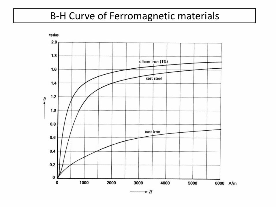
B-H Curve of Ferromagnetic materials

Orientation of magnetic domains without and with the presence of an external magnetic field
Without external magnetic field With external magnetic fiedl

Saturation curves of magnetic and nonmagnetic materials

Residual induction and Coercive Force

Hysteresis Loop traced by the flux in a core under AC current

Faraday’s Law
• Faraday's law of induction is a basic law of electromagnetism relating to the operating principles of transformers, electrical motors and generators. The law states that:
“The induced electromotive force (EMF) in any closed circuit is equal to the time rate of change of the magnetic flux through the circuit”, or alternatively, “the EMF generated is proportional to the rate of change of the magnetic flux”.
dt
dNe

Voltage induced in a coil when it links a variable flux in the form of a sinusoid

Inductance of a coil
l
ANL
dt
dilAN
dt
lANidN
dt
dN
dt
diLe
22 )/(
)/(

Transformers