review article review of response and damage of linear and
TRANSCRIPT

Review ArticleReview of Response and Damage of Linear and NonlinearSystems under Multiaxial Vibration
Ed Habtour,1 William (Skip) Connon,2 Michael F. Pohland,3 Samuel C. Stanton,4
Mark Paulus,5 and Abhijit Dasgupta6
1 Vehicle Technology Directorate, US Army Research Laboratory, APG, MD 21005, USA2US Army Aberdeen Test and Center (ATC), APG, MD 21005, USA3US Army Materiel System Activity Analysis (AMSAA), APG, MD 21005, USA4US Army Research Office, Durham, NC 27709, USA5Naval Undersea Warfare Center Division, Keyport, WA 98345, USA6Center for Advanced Life Cycle Engineering (CALCE), University of Maryland, College Park, MD 20742, USA
Correspondence should be addressed to Ed Habtour; [email protected]
Received 17 July 2013; Accepted 5 February 2014; Published 10 April 2014
Academic Editor: Nuno Maia
Copyright © 2014 Ed Habtour et al. This is an open access article distributed under the Creative Commons Attribution License,which permits unrestricted use, distribution, and reproduction in any medium, provided the original work is properly cited.
A review of past and recent developments in multiaxial excitation of linear and nonlinear structures is presented. The objective isto review some of the basic approaches used in the analytical and experimental methods for kinematic and dynamic analysis offlexible mechanical systems, and to identify future directions in this research area. In addition, comparison between uniaxial andmultiaxial excitations and their impact on a structure’s life-cycles is provided.The importance of understanding failuremechanismsin complex structures has led to the development of a vast range of theoretical, numerical, and experimental techniques to addresscomplex dynamical effects. Therefore, it is imperative to identify the failure mechanisms of structures through experimental andvirtual failure assessment based on correctly identified dynamic loads. For that reason, techniques for mapping the dynamic loadsto fatigue were provided. Future research areas in structural dynamics due to multiaxial excitation are identified as (i) effect ofdynamic couplings, (ii) modal interaction, (iii) modal identification and experimental methods for flexible structures, and (iv)computational models for large deformation in response to multiaxial excitation.
1. Introduction
The study of fatigue failure was instigated in the 19th centuryfollowing several catastrophic train accidents [1]. This fieldhas evolved drastically to include substantial scientific effortsto gain an understanding of failure mechanisms in structuresunder dynamic loading [2–10]. The scientific studies offatigue accelerated in the 1940s to mitigate fatigue failuresseen in military systems during World War II. These studiesbegan to include multiaxial loading in the 1960s; such studiesincreased significantly in the 1990s due to the proliferation ofcomplex components in the electronics, military, aerospaceand automotive platforms [2]. In spite of the significantaccomplishments achieved in the twentieth century theintroduction of sophisticated and high precision devices inthe 2000s, such as micro/nanoelectromechanical systems
(MEMS/NEMS) and electronics, has exposed the limitationof our knowledge of fatigue due to multiaxial vibration.Researchers are still struggling to systematically model high-cycle fatigue of linear and nonlinear structures under multi-axial loading; thus, predictionmethods for high-cycle fatiguelife remain somewhat immature. Life-cycle prediction undermultiaxial dynamic loading has been shown to be extremelycomplex andmore intractable than uniaxial models [11].Thisis primarily because the validation of multiaxial models isextremely difficult since multiaxial vibration shakers, shownin Figure 1, are complex, costly, and extremely limited [12].
The initial assumption at the beginning of this literaturereview was that there would be an abundance of researchperformed inmultiaxial vibration sincemostmechanical andelectronics products are universally subject to multidegreesof freedom (MDoF) dynamic loading. However, only limited
Hindawi Publishing CorporationShock and VibrationVolume 2014, Article ID 294271, 21 pageshttp://dx.doi.org/10.1155/2014/294271

2 Shock and Vibration
Electricalamplifiers
Shaker table on12 actuators
Table
Electricaldistribution
boxHydraulic
unit
8 in-plane actuators (4 out-of-plane actuators areunderneath the table)
Frame
Figure 1: Six-DoF electrodynamic shaker at CALCE (with TEAM Inc. permission).
life-cycle modeling studies focusing on multiaxial vibrationhave been published in the literature. Analytical and exper-imental investigations of structures exposed to multiaxialharmonics and random loading are also scarce. Most stud-ies found in the literature are focused on uniaxial load-ing. Furthermore, military and commercial standards weredeveloped to mitigate the testing limitations by proposingsequential uniaxial excitation as a compromise and proxyfor simultaneousmultiaxial excitation. In qualifying productssubject to vibration, it is common to test sequential uniaxialvibration profiles found in standards such asMIL-STD-810G.Unfortunately, current standards do not provide vibrationprofiles for simultaneous multiaxial vibration. Single axiselectrodynamic and hydraulic shakers have been the prevail-ing tools for performing harmonic and random vibrationtesting. Unfortunately, uniaxial sequential testing may pro-vide overly optimistic fatigue durability results [10, 13].
While several different schemes are widely used to testdevices sequentially in the various axes, it is understood thatthey are rough approximations to the ideal of simultaneousmultiaxial testing and must be in the linear regime. Uniaxialexcitations are applied to test products even thoughmost fieldoperational data indicate that these products are exposed tomultiaxial dynamic loading environments. Examples includea spacecraft launch, a military ground vehicle over roughterrains, a helicopter blade during instability, and an aircraftwing exposed to turbulent flow. Thus, serious compromisesmust be made in the experimental design to perform mean-ingful tests on a single-axis electrodynamic shaker. For exam-ple, to simulate multiaxial vibrations, the MIL-STD-810Grecommends performing the vibration tests by sequentiallyapplying single axis excitation to a test article along threeorthogonal axes (X, Y, and Z). This can be accomplishedby exciting the structure in one direction then repeating theprocedure twice after rotating the structure 90∘ each time.Depending on the complexity of the structure, this proceduremay require designing a different fixture for each rotation.
Understanding the failure mechanisms due to complexvibration loading is becoming increasingly important forcurrent systems that are progressively complex and electron-ically rich [14]. These failure mechanisms can be exploitedthrough accelerated multiaxial vibration testing, which may
provide reliability improvements at significantly lower cost[15]. Unfortunately, difficulties encountered in this approachhave limited its application and acceptance. Some of thesedifficulties can be traced, in part, to a lack of understanding ofthe propagation of multiaxial dynamic loads from the systemlevel to individual components. To appreciate a particularfailure mechanism by means of testing, it is important toresolve the dynamic loads by simulating the actual vibrationconditions, which can be accomplished with a multiaxialshaker.
The objective of this literature review is to provideengineers and researchers with an overview of the work thathas been done in the area of uniaxial andmultiaxial vibration.The review provides most of the significant accomplishmentsin the past century in uniaxial and multiaxial vibrationand high-cycle fatigue. State-of-the-current technologies andstate-of-the-art technologies are provided. The review isbroken into four major parts: the first section focuses on theindustrial studies and research in complex dynamic loadingand high-cycle fatigue, whereas the second part focuses onthe theoretical and experimental aspects. The third sectiondiscussesmapping fatigue tomultiaxial dynamic loading.Thefinal portion of this paper summarizes proposed and futureefforts in the field of multiaxial vibration.
2. Applied and Industrial Contribution
This section provides an overview of uniaxial and multiaxialvibration studies performed by the automotive, aerospace,and electronics industries. These three industries have devel-oped a great wealth of data, standards, methodologies, andmodels for dealing with vibration fatigue.
2.1. Automotive Applications. The automotive industry hasproduced an abundance of publications on the use of uniaxialandmultiaxial excitation for durability and qualification test-ing, to meet warranty and reliability requirements demandedby consumers. A typical automobile prototype is subjectedto a variety of vibration profiles that simulate operationalconditions in a laboratory environment. According to DoddsandWard [16] andAwate et al. [17] automotivemanufacturers

Shock and Vibration 3
Figure 2: Four-post hydraulic simulator, from Awate et al. [17].
utilize accelerated life testing for critical components tomeet the life-cycle requirement while reducing the testingcost. This can be accomplished by driving on various roadsurfaces (proving grounds) similar to those seen in the field.During testing, acceleration data are collected for the criticalcomponents.Themeasured conditions are then simulated onshakers in the test laboratory, where the critical componentsare exposed to similar dynamic conditions, but accelerated.Another approach that automotive manufacturers rely on isthe four-post hydraulic shaker. This is a common testing toolfor validating vehicle durability [17]. It is a relatively simpleand cost effective configuration for performing a completevehicle vibration evaluation. A typical four-post hydraulicshaker consists of four vertical servohydraulic actuators fora simple shaker to four actuators in the vertical direction andeight actuators in the transverse direction for more advancedshakers (total of twelve actuators, three actuators per post) tosimulate amultiaxial environment A simple four-vertical ser-vohydraulic shaker, which excites a vehicle through its tires, isshown in Figure 2. Similar to the component accelerated lifetesting, the wheels’ accelerations and forces and the wheel-to-body displacements data obtained from the proving groundcan be reproduced by such a shaker. The dynamic loadingproduced by the shaker induces stresses on the vehicle andits components. However, using a four- or twelve-hydraulicactuator shaker introduces two major limitations [17, 18].The first limitation is the inability to simulate the effectof rolling tires on the overall stiffness and damping of thesuspension system and vehicle structure. The second issueis that hydraulic shakers have limited frequency range, ingeneral 1–80Hz [16].
Because of these limitations, estimating and modelingvibration fatigue for components in higher frequency rangescan be an arduous task. High-frequency dynamic loading,especially random loading, is a major contributor to fatiguein vehicular components [19]. These high frequencies caneasily generate other high frequencies caused by rotatingspeeds, random vibration, and noise radiation that canpotentially augment the severity of damages. These high-frequency loads are transmitted from the chassis to thevehicle body and eventually to the components [20]. One ofthe commonmultiscale hierarchical approaches formodelingfatigue in vehicular components is to model global dynamic
responses of the vehicle and progressively generate the effectof these responses on the vehicle subsystems and eventuallyon individual components, which can be an expensive andtime consuming approach. Another common approach is torely on engineering judgment in assuming realistic boundaryconditions and loads directly at the subsystem or componentlevel. Subsequently, finite element methods (FEM) are usedfor stress and fatigue assessment, based on these assumptionsand on linearizing approximations of the structure, whichmay lead to erroneous results and vehicle recalls. Liu [20] sug-gested a more practical approach where FEM is coupled withexperimental transfer functions. Liu detailed a methodologyfor extracting an experimental frequency response function(FRF) that represents the body and then combining it withthe FEMmodels.
As mentioned above, random vibration in automobiles isone of the major contributors to fatigue damage. Typically,automotive fatigue researchers rely on power spectral densi-ties (PSDs) to represent stochastic dynamic behaviors [18, 21–24]. A detailed approach to estimating fatigue life due to ran-domvibration loading for a truckwas provided by Bonte et al.[22]. They developed an analytical model where symmetricin-phase road excitations were applied to all wheels of a fulltruck. They also applied asymmetric excitations (180-degreephase difference) to the left and right tracks to generate out-of-phase conditions. Biaxial stress power spectral densities(PSDs)were calculated frommultiple randomexcitations andequivalent von Mises’ stress PSDs were derived. Later, Bonteet al. [23] developed a new analytical approach to estimatingthe equivalent von Mises’ stress PSDs from several randomvibration inputs while accounting for phase differences. Thedamage ratio was then calculated based on a uniaxial fatigueanalysis approach based on the Dirlik method [25]. Thisapproach provided qualitative results for design improve-ments to linear structures that can be implemented as a fasttool to evaluate different design concepts and the effect ofdynamic loading on fatigue life.
Unfortunately, these tests and analytical tools are notalways successful in producing failures observed in the field.The Ford Corporation found that a module could pass thequalification test but fail in the field [26]. A test or healthmonitoring system that could capture every failure or inter-mittent in real time does not exist. In spite of the great wealthof fatigue research generated by the automotive industry,the industry continues to maintain the same practice ofqualifying their products by subjecting them to uniaxialvibration with the option of sequential vibration testing.However, there seems to be consensus in the literature thatsuch an approach can be both time consuming and costineffective and may result in the acceptance of unreliablecomponents.
2.2. Aerospace Applications. Surprisingly, studies publishedin the open literature pertaining to uniaxial and multiaxialvibration testing for aerospace applications are somewhatlimited.This is due to the proprietary nature of the aerospaceindustry. In aeronautic applications, the majority of thedynamic loads stem from turbulent flow and during landing

4 Shock and Vibration
and takeoff, which are multiaxial in nature. Aircraft wings,for example, are constantly exposed to multiaxial dynamicloading since the wings are connected to a flexible support,such as the fuselage. In addition to bending in the wing,the root of the wing experiences dynamic rotation becauseof the inherent flexibility at the point of attachment [27]. Inastronautic applications, one of the most critical and persis-tent spacecraft design problems is the launch survivabilityof sensitive and expensive systems. The acceleration levelsinput to a typical spacecraft are over a wide frequency rangefrom about 30Hz to 2000Hz or higher [15]. Billions of dollarsin lost satellites or degraded performances of payloads areattributed to damage accumulated from vibration due tolaunch loads [28].
In spite of the lack of specificity of multiaxial vibrationand fatigue in aerospace applications, most of the multiaxialloading investigations performed by aerospace researchershave focused on the dynamics of beam-like structures asidealization of the of helicopter blades, aircraft wings, ordeployable solar panels in satellites [27, 29–32]. Only twomajor studies, at the system level, are reviewed in this section.The first study is an early investigation of the dynamics ofa blade in a compressor [33]. The other is a more recentstudy of fatigue assessment of a military helicopter flare-dispenser bracket [34]. In the study performed by Whithead[33], experimental the power spectra of vibration responsewere measured for blades in axial compressors exposed toturbulent flow. In deriving the equations of motion, theeffect of aerodynamic coupling between the blades wasassumed to be a minor effect and thus neglected. Aykanand Celik [34] compared fatigue damage accumulated underuniaxial and multiaxial broadband random excitation. ThePSD of the dynamic response was obtained for a militaryhelicopter flare-dispenser aluminum bracket during flight.The PSD profile was used as an input for uniaxial excitationtesting. However, due to lack of multiaxial excitation testingcapability, the simultaneous three-axial loading was modeledusing FEM to calculate the structural response. Similarto most studies found in the literature, Aykan and Celikassumed that sequential uniaxial loadings were equivalent tomultiaxial loadings.Thus, the fatigue analysis was performedin frequency domain with the assumption of linear structuralbehavior.They concluded that the cumulative fatigue damagein multiaxial excitations was higher than adding the damagefor sequential axes even for linear structures. It is importantto point out that, for military aircraft, the MIL-STD-810Gprovides single-axis PSD profiles for simulating the dynamicinputs in various fixed-wing aircrafts and in rotorcrafts.
2.3. Electronics Applications. One of the predominant failuremodes in electronics is solder joint fatigue due to vibrations[35, 36]. Analyses of solder joint stresses associated with uni-axial vibration are widely seen in the literature: Lau et al. [37–39], Liu et al. [40], Yang et al. [41], and Zhou et al. [42]. One ofthe most detailed methodologies for monitoring, recording,and analyzing life-cycle vibration loads of electronics wasdeveloped byGu et al. [43].They developed thismethodologyby exciting circuit card assemblies (CCAs) in the out-of-plane
direction using broadband PSD profiles. Strain data wascollected for different PSD levels from a series of experiments.FEM simulation was then conducted and calibrated based onthe experimental responses of the CCAs. A strain transferfunction was calculated to predict the damage ratio in thesolder where the structure was assumed to be linear. Unfortu-nately, literature does not provide anymethodology that con-siders multiaxial vibration in electronics systems. Zhou et al.[36, 42] estimated vibration fatigue of Sn3.0Ag0.5Cu andSn37Pb solders forCCAs exposed to linear harmonic uniaxialexcitation.The analysis was conducted in the time domain toquantify the fatigue damage caused by harmonic excitation atthe first natural frequency. In their study, they observed twocompeting failure sites in the solder interconnect and in theprintedwiring board (PWB) copper trace just below the failedcomponents. Several researchers studied high-cycle fatigue inCCAs exposed uniaxial harmonic and random excitations inthe range of 10Hz to 10 kHz [36, 42, 44–48]. Based on thisextensive literature review, there are two multiaxial vibrationfatigue studies in electronics components. The first studyby Habtour et al. [15] provided a rapid analytical techniquefor analyzing the response of heavy/large components underbiaxial random vibration excitation. A modified 2-D FEMsmeared technique was used to model the CCA, which wascoupled with a detailed local 3D FEM for heavy components.Based on the knowledge of the effective moment-curvaturerelationship near the component of interest, a local effectivestiffness was calculated. This was accomplished through theuse of Kirchhoff-plate moment-curvature equations. Themodified smeared technique correctly predicted the overallstiffness of the CCA and produced an accurate PWB firstmode frequency; however, the model does not take intoaccount the inertial effect of the large component on theoverall response of the CCA.The second study by Ernst et al.[49] is the only experimental study that exposed heavy/largeelectronic components to biaxial planar random excitations.This study is discussed in detail later in this paper in thesection titled “Mapping Dynamic Loads to Fatigue.”
3. Theoretical Approach
3.1. Beam Vibrations. The beam has many characteristicsof typical aeronautical and astronomical structures. Indeed,high aspect ratio aircraft wings, spacecraft deployable solarpanels, and helicopter rotor blades are frequently idealizedas beams. Even for low aspect ratio wings, the bending andtorsional deformation can be approximated by use of beamtheory with an adjusted stiffness [27].
3.2. Stochastic Vibrations. There have been significant scien-tific contributions in stochastic vibrations since the 1950’s.During that time, random vibration received significantattention due to its importance in fatigue damage in aircraftand naval ships. One of the earlier studies in randomvibration of beams was performed by Eringen [50], wherehe derived a closed-form solution for space-time correlationfunctions of a simply supported beam. Eringen employedgeneralized harmonic vibration analysis of damped beams

Shock and Vibration 5
exposed to one-dimensional randomly distributed exter-nal pressure loads. His approach provided cross-correlationfunctions for displacements and stresses in terms of theexternal pressure cross-correlation function. Herbert [51]applied Markoff process and Fokker-Planck equations toinvestigate large vibration of a simply supported elastic beamexposed to broadband white noise external pressure actingon the entire beam surface. He obtained the joint probabil-ity density function (PDF) of the modal amplitudes usingthe Fokker-Planck equation. An approximate expression forthe mean-squared displacement of the beam was derivedand was then compared to numerical computation, whichindicated a reduction in the mean-square displacement dueto the nonlinearity. Herbert [51] also showed that whenthe deflection was sufficiently large, the first mode stillrepresented a good estimate of the total mean-squareddeflection; however, the effect of the higher modes must beconsidered in calculating the response of the first mode. Thestudies reported by Herbert lacked experimental validation.Elishakoff and Livshits [52] utilized Eringen’s and Herbert’sfindings to produce closed-form solutions for a simply sup-ported Euler-Bernoulli beam under random vibration withdifferent damping mechanisms. The excitation was spatiallyand temporally random stationary white noise induced onthe entire bottom surface of the beam. Elishakoff stated thatusing a span averages approach instead of the maximumrandom vibration responses could yield an underestimate ofthe stresses. In a different study, Elishakoff [3] generalized theEringen problem to include the effect of axial loading on abeam exposed to a random transverse load. Later, Elishakoffet al. [53] employed a stochastic linearization to investigatelarge amplitude random vibrations of simply supported andclamped beams on an elastic foundation under a stochasticloading. He stated that, for different boundary conditions andthe loading patterns, the stochastic linearization method wassuperior to the classical stochastic technique, especially innonlinear structures. Ibrahim and Somnay [54] investigatedthe response of an elastic Euler-Bernoulli beam with onefrictional support at each end, which was exposed to singlepoint harmonic and stochastic excitations (randomized onlyin time). The beam was allowed to slide on the two frictionalsupports. A Monte Carlo simulation was utilized to estimatethe beam mean-square response for the stochastic excitationcase. For the harmonic excitation case, the quality factorimproved as the excitation frequency increased beyond theresonance frequency. The friction in the random excitationcase caused a significant reduction of the systemmean-squareresponse.
3.3. Nonlinear Vibrations. Substantial attention has beendevoted to nonlinear dynamics and vibrations of beamsbecause of their vital importance in many engineering appli-cations and fatigue problems. One of themost cited studies innonlinear dynamics is the work of Hodges and Dowell [32],where they developed the multiaxial equations of motionfor a rotor blade, idealized as a cantilevered beam, usingHamilton’s principle. They maintained the cubic nonlinearterms and included the effect of warping. Ho et al. [55, 56]
examined free and forced nonplanar oscillations of fixed-fixed and cantilever inextensional beams, respectively. Hoet al. reduced the nonlinear partial-differential equationsof motion to two coupled nonlinear ordinary-differentialequations using separation of variables, where they assumedonly one mode in each plane. They also ignored the axialinertial and Poisson effects. It was concluded that whirlingoscillations might occur for significantly large excitationamplitude. Crespo da Silva and Glynn [57, 58] developeda set of partial-differential equations for flexural-flexural-torsional motions of inextensional beams, which containedgeometric and inertial nonlinearities. It was found that thegeometric nonlinearities were critical for low modes andmust not be neglected. Later, Da Silva [29] extended the aboveapproach to extensional beams where he constructed partial-differential equations for flexural-flexural-torsional motions.The axial displacement due to warping was consideredin the derivations. These equations were then applied tostudy the nonlinear response of an extensional cantileverbeam to a fundamental resonant excitation [59]. Crespo daSilva concluded that the nonlinear terms due to midplanestretching were predominant in extensional beams. Nayfehand Pai [60] and Pai and Nayfeh [61] also investigatednonlinear nonplanar responses of inextensional cantileverbeams to parametric and resonant excitations using thepartial-differential equations of motion developed by Crespoda Silva and Glynn [58]. The method of multiple scaleswas utilized to construct nonlinear first-order ordinary-differential equations governing themodulation of the ampli-tudes and phases of the interactingmodes in each plane.Theyconclude that the geometric nonlinear terms had a stiffeningeffect, whereas the inertial terms had a softening effect.Crespo da Silva and Zaretzky [30] and Zaretzky and Crespoda Silva [62] continued to study the nonlinear responseof an inextensional beam exposed to one of the flexuralmodes resonant excitation. The method of multiple scaleswas applied to the governing partial-differential equations toproduce the equations of motion that provide the capabilityfor modulating the amplitudes and phases of the beaminteracting modes. Arafat et al. [63] showed that the partial-differential equations of motion of Crespo da Silva andGlynn [57, 58] can be derived using Hamilton’s extendedprinciple. Nayfeh and Arafat used the method of multiplescales to the Lagrangian terms to derive the modulationequations for amplitudes and phases of the two interactingmodes [64]. Nayfeh and Arafat [65] and Arafat [66] derivedthe Lagrangian equations of motion for nonlinear flexural-flexural-tensional vibrations of symmetric laminate com-posite and isotropic metallic long slender cantilever beamswith nearly square cross-sections under uniaxial harmonicexcitation of the base. Perturbation procedure was thenapplied to establish approximate solutions for the weaklynonlinear equations of motion. The beam was assumed tobe inextensible with negligible torsional inertia, leading totwo partial-differential equations governing the motions ofthe beam. Banerjee [67] provided amethodology for derivingexact expressions for the mode shapes of free vibration ofcomposite beams.The effect ofmaterial coupling between thebending and torsional modes was considered. The equations

6 Shock and Vibration
of motion of the bending-torsion were solved analyticallyfor bending and torsion. Malatkar and Nayfeh [68, 69]and Malatkar [70] extended Arafat’s equations of motiondevelopment to their experimental and theoretical study ofthe response of a flexible long cantilever beam exposed toexternal single axis harmonic plane excitation near the beamthirdmode.They observed that the beam response containedsignificant contributions from the first mode when the beamthird mode amplitude and phase were slowly modulated.Theenergy leakage between these modes depended on how closethe modulation frequency was to the frequency of the firstmode.
Anderson et al. [71] experimentally investigated theresponse of a thin steel cantilever beam with an initialcurvature to a combination parametric excitation exposedto uniaxial base excitation. The first four natural frequencieswere 0.65, 5.65, 16.19, and 31.91Hz.Their study suggested thatover a range of forcing frequency above 32Hz, the first andfourth modes were initiated by a combination parametricresonance with the first mode dominating the response.The experimental results confirm the occurrence of externalsubcombination resonances in structures found in the studyby Dugundji and Mukhopadhyay [72]. These resonances canbe utilized asmechanisms for instigating large amplitude low-frequency modes with high-frequency excitations.
The dynamics of nonlinear beams with complicatedboundary conditions were also investigated. Dowell [31] per-formed an analytical study of large motion of axially slidingbeams with dry friction damping. In Dowell’s study, an Euler-Bernoulli beampinned at both endswas considered; however,the beam was fixed at one end against the axial motionand with a sliding restraint. Coulomb dry friction dampingwas assumed. The Galerkin modal solution method wasapplied for a single mode. Dowell concluded that, for largebeam response, damping was created due to dry friction andequivalent to a linear viscous damper. Tang and Dowell [73]performed a numerical and experimental study to supportDowell’s analytical work [31] using a pinned-pinned beamunder single axial harmonic excitation for slip and no-slipconditions. Their model was more reliable for the first modethan higher modes and can be applied to a beam with well-separated modes.
Sophistications were added to beam models to idealizemore complex structures such as antenna and radar struc-tures and aircraft wings. This can be achieved with cantileverbeams or L-shape beams models with tip mass under a baseexcitation. To [74] analyzed the dynamics of an antennaby deriving the natural frequencies and mode shapes of acantilever beam with an eccentric tip mass under a baseexcitation. To assumed small deflection and neglected theeffect of the axial deflection due to the heavy mass at thetip. The model was appropriate only for linear structureswith uniaxial excitation. Later, Cartmell and Roberts [75]conducted a theoretical and experimental investigation ofthe stability of a cantilever beam with tip mass having twosimultaneous combination parametric bending and torsionresonances. The multiple scales method was utilized. Itwas possible to reach an agreement between theoreticaland experimental results within limited ranges of excitation
Mode shapes
S.G.Accl.
S.G.l
Shaker
f2 ≈ 2f1
X
M2
M1
f2f1D
L1
L2
Figure 3: L-shape structure excitation, Balachandran and Nayfeh[77].
frequency, but unattainable in periodic modulation regions.Cartmell and Roberts did not consider the effect of inherentnonlinearities in the system. In 1990, Balachandran andNayfeh [76] reported the planar response of a flexible L-shaped beam-mass structure with the second natural fre-quency twice the first natural frequency of the structure,as shown in Figure 3. They showed that weakly nonlinearanalysis can be used to qualitatively and quantitatively predictthe response of an internally resonant structural system sub-jected to small primary resonant excitations. Balachandranand Nayfeh developed the Lagrangian for weakly nonlinearmotions of the L-shape structure where they assumed thatthe structure was undamped. It was possible through theirapproach to identify theHopf bifurcations, thereby ascertain-ing the parameters that control the possibility of periodicand chaotic modulated motions. Later, Balachandran andNayfeh [77] presented experimental results on the influenceof modal interactions on the nonlinear response of the L-shape structure.Themajor conclusion was that the frequencyrelationships between the different modes of oscillation inthe structures led to modal interactions during the resonantexcitations and nonlinear responses. Jaworski and Dowell[78] performed a theoretical and experimental investigationof the free vibration of a cantilevered beam with multiplecross-section steps. The natural frequencies were obtainedexperimentally usingmodal impact testing.The experimentalresults were then compared against Euler-Bernoulli beamtheory solutions from Rayleigh-Ritz FEM results, where theasymptotic approximation was utilized for higher modes toavoid numerical error. A detectable difference in the firstin-plane bending natural frequency was noted between thebeam theory results and those of the higher-dimensionalFEMmodels and experimental observation.
3.4. Microsystems Vibrations. For the past two decades,consumers’ demand for miniaturized smart devices hascontinued to increase at a considerable pace. As a result,microsystems devices have become ubiquitous in almostevery product that humans interact with on daily bases suchas smart phones, computers, medical devices, and automo-biles. Recent advancements in microsystems fabrication have

Shock and Vibration 7
allowed for new possibilities in designing an assortment ofmicrostructures such as piezoelectric energy harvesters, sen-sors, accelerometers, bistable piezoelectric devices, microgy-roscopes, andMEMS [79, 80]. Fortunately, these microstruc-tural components’ behavior can be formulated based onthe Euler-Bernoulli beam or Timoshenko beam theory [81–85]. Researchers have investigated both linear and nonlinearvibration based energy harvesting devices, in which thesedevices were modeled using beam theory [84, 86–90]. Beamtheory was also extended to nanomechanical cantilevers,such as the efforts performed by Villanueva et al. [91].Some of these microstructures are submerged in fluids withvarious viscosities to achieve optimal performance, such asthe work presented by Green and Sader [86].They developeda theoretical model for the torsional response of a linearcantilevered beam excited by an arbitrary driving force whilesubmerged in a viscous fluid. Esmaeili et al. [84] developedequations of motions for a microgyroscope, which wasmodeled as a linear cantilever beam with a tip mass exposedto excitation at the base. Their governing equations werederived from Hamilton’s principle with a 6-DoF base motionwhere the torsion was neglected. Esmaeili et al. resolved themeasurement error in oscillating gyroscopes due to cross-axiseffects resulting from a combination of lateral rotation andlongitudinal speeds in the linear regime.
Ansari et al. [79] developed an exact frequency analysisof a rotating beam with an attached tip mass while the beamundergoes coupled torsional-bending vibrations, where thebase angular velocity was the instigator of the coupling.The extended Hamilton principle was utilized to derive thecoupled equations of motion and the associated boundarycondition. Ansari et al. demonstrated that the undampedstructure experiencing base rotation has complex eigenval-ues, which revealed a damping behavior. They also showedanalytically that increases in the rotational velocity cause anincrease in the frequencies. Later, Ansari et al. [81] presenteda more complex vibration and parametric sensitivity analysisof a vibrating gyroscopic microdevice. The device consists offour beams attached to a stiff substrate with a mass at thecenter, as shown in Figure 4. Thus, the device experiencedcoupled flexural and torsional responses.The results obtainedfrom their analysis revealed that an increase in the baserotation increased the real and imaginary components of theeigenvalues.
Kumar et al. [92] studied the effects of structural andinertial nonlinearities on near resonant response for a flexiblecantilever inextensional beam exposed to base excitationcombined with simultaneous parametric excitation. Theyconducted base excitation experiments for a cantileveredspring steel beam: 190 × 19 × 0.5mm3, which was orientedat 80∘ angle to induce both direct and parametric excitations.The energy method was utilized to derive the governingequations for their structure, where the rotational inertiaand the torsion were assumed negligible [93]. Kumar et al.claimed that this work provided a baseline understanding ofthe effect of nonlinearities on parametrically excited systems.
It was apparent during this literature review that res-onant energy harvesters were analyzed and designed foruniaxial base excitation at a single frequency, whereas many
Beam 2(PZT sensor)
Beam 4(PZT sensor)
Beam 3(PZT actuator)
Beam 1(PZT actuator)
Centered mass
Figure 4: Schematic of a rocking-mass gyroscope Ansari et al. [79].
real-world applications encompass multiaxial excitations,broadband spectrum, and time varying dynamic loading. Interms of multiaxial excitations for microsystems, the onlystudy that can be found in the open literature is the workof Esmaeili et al. [84]. Limited studies were found in theliterature that investigated energy harvesters for time varyingbroadband random excitations [80, 85, 94]. Ali et al. [94]employed a linearized stochastic methodology to a cantileverbeam configuration energy harvester exposed to uniaxial sta-tionary Gaussian broadband base excitations. Wickenheiser[80] developed an optimization methodology for designinglinear and nonlinear vibration energy harvesters for max-imizing power production by vibrations due to uniaxialbroadband random loading environments at low frequencies.Wickenheiser [80] also linearized his approach by employinga close form approximation. Stanton et al. [85] investigatedthe nonlinear dynamics and stability of a broadband energyharvester under broadband random excitation.The harvesterwas modeled analytically and numerically as a cantileverbeam with tip mass under uniaxial broadband base excita-tion, which were validated experimentally. Stanton et al. [85]considered the bifurcation parameter within the harvester aseither a fixed or an adaptable tuningmechanism for enhancedsensitivity to broadband random excitation. Later, Stantonet al. [87] modeled nonlinear damping of uniaxial weaklyexcited piezoelectric actuators, which included nonconser-vative piezoelectric constitutive relations. In their analysis, apiezoelectric actuator was idealized as a cantilever beamwithtip mass. Stanton et al. showed that the tip mass precipitatednonlinear resonances at lower base excitations. Stanton et al.[88] extended the method of harmonic balance to estimatethe presence and impact of a bistable piezoelectric inertialgenerator. In theirmodel, they included nonlinear dissipationand cubic softening influences in the electroelastic laminates.Westra et al. [89] investigated the interactions between adirectly and a parametrically excited mode of a clamped-clamped micromechanical beam resonator. They were ableto detect the motion of a parametrically excited mode thatprovoked a change in another mode of the same structure.They demonstrated that the parametric excitation of onemode instigated a change in the fundamental frequency ofthe other modes.
8 Shock and Vibration
3.5. Nanosystems Vibration. Nanomechanical cantileversrecently received increased consideration in biomedicalsensing and prognostics and diagnostics applications. Thebiomolecular community deserves the majority of the creditfor accelerating the research in nanomechanical cantileversby generating applications that ranged from high-throughputbiomolecular detection to bioactuation [95]. Biomolecu-lar researchers and physicists suggested that the cantilevermotion of DNA can be manipulated by controlling theentropy change during DNA hybridization [95]. Later sci-entists were able to measure the resonant frequency shiftbased on a nanomechanical cantilever augmented with anactuating layer for the detection of a prostate-specific antigenin fluid setting [96]. Dorignac et al. [97] estimated thestochastic dynamic response of biofunctionalized structuresby utilizing the nanomechanical cantilever beam idealiza-tion. Their model assumed that the structure was linearand immersed in viscous fluid, where random excitationsare generated by biomolecular interactions only; the modelignored any inertial loading. Salehi-Khojin et al. [98] pre-sented a modeling approach to dynamic characterization ofnanomechanical cantilevers with geometrical discontinuities.The linear analysis provided eigenvectors and eigenvaluesfor the first three modes and compared them with thoseobtained from the experiment and theory for uniform beams.The uniform beam theory was unsuccessful in predictingthe system’s response, while the discontinuous beam modelprovided better estimates. Seena et al. [99] studied themechanical and dynamic characteristics of highly sensitivepiezoresistive nanomechanical cantilever sensors in detectingexplosives in vapor phase, where the system was assumedto be linear. There were limited studies that investigatedthe nonlinear dynamic characterization of nanomechanicalcantilever beams. Villanueva et al. [91] investigated thefidelity of Euler-Bernoulli’s beam theory in estimating thedynamic response of nanomechanical cantilever beams inthe nonlinear domain, where the beam was exposed tosingle axial harmonic base excitations. They showed that theEuler-Bernoulli’s beam theory predictions differ significantlyfrom their measurements for the nonlinearity of the firstfundamental mode.
4. High-Cycle Fatigue
The main objective of this section is to provide a generaloverview of the available literature on high-cycle fatigue,with an emphasis on uniaxial and multiaxial harmonic andrandom dynamic loading. A brief review of early fatiguestudies is provided; however, the core of this review isfocused on recent theoretical, experimental, and computa-tional advancements.The railway industry deserves the creditfor instigating serious scientific studies for understanding,analyzing, classifying, and mitigating cyclic fatigue in thelate 1800’s. One of these early studies was by Wohler, whois considered one of the earliest pioneers of fatigue, forinvestigating fatigue failures in railway carriage axles [2].Industrial investment in fatigue studies in the early 20thcentury led to the popular exponential relationships between
stress amplitude and loading cycles by Dowling and thesecondary effect on life due to mean stresses by Suresh [2,100]. In many of these efforts, the focus was on stressesdue to a constant amplitude sinusoidal loading, which ledto the sinusoidal fatigue equations found in many fatiguetextbooks [2, 101]. Significant considerations were dedicatedto examining the mean stress effects for fatigue in welds dueto harmonic and random loading [102, 103].
4.1. Uniaxial Loading. There are many circumstances infatigue problems where it is unrealistic to always considera constant amplitude sinusoidal loading. Examples of suchcases are components in an off-road vehicle, electroniccomponents in a rotorcraft, and an aircraft wing exposedto turbulent flow. Methods and standards were developedto determine the time to failure (TTF) with constant andvariable loading amplitudes. The most well known is the“linear cumulative damage rule” for variable amplitudeloading, which was attributed to Palmgren [104] and laterpopularized by Miner [105]. The Palmgren-Miner rule rea-soned that fatigue damage is cumulative; thus, each stresscycle contributed to damage as a function of the numberof cycles to failure for that cycle amplitude. Their linearcumulative damage approach neglected any sequence effectsthat may change fatigue life, that is, low amplitude stressfollowed by high amplitude versus the opposite sequence.Later, Miles [106] utilized the Palmgren-Miner cumulativedamage rule for analyzing narrowband random vibrationfatigue. The linear summation of damage was extended toan integral of stress peaks scaled by the PDF of the peaksfor a narrowband random vibration fatigue problem. Theresulting damage equation was a function of the sinusoidalstress versus the number of fatigue cycles (known as S-N curve), the material fatigue constants, and the standarddeviation of stress. Crandall [107] and Lin [108] producedinfluential studies on nonlinear response PDFs and theireffect on fatigue. Crandall developed equations for the ratesof zero crossings for nonlinear non-Gaussian systems forstructures with nonlinear restoring forces. The analyticalrelationship that Lin developed for nonlinear stress PDFs wasbased on a quadratic displacement to stress equation, wherethe displacement PDF was assumed to be nonlinear.
The narrowband random vibration loading case, deserv-ingly, received significant attention in the 1960’s. Bendat[109] proposed the first significant step towards a method ofdetermining fatigue life from the PSDs. For a narrowbandtime history loading, Bendat assumed that correspondingdepressions of comparable size would follow positive peaksin the time history. Using this method, it was shown thatthe PDF of peaks for a narrowband signal tended towardsa Rayleigh distribution. Bendat used a series of equationsderived by Rice [110] to estimate the expected number ofpeaks usingmoments of area under the PSD.Thenarrowbandsolution was extremely conservative when broadband timehistory profiles were used. This was due to the assumptionthat peaks were matched with corresponding troughs of sim-ilar magnitude. The narrowband random vibration loadingcase was extended to arbitrary stress cycles using loading

Shock and Vibration 9
cycle versus amplitude counting methods. The narrowbandtime-domain approach emerged as the standard method inestimating the fatigue life of structures, widely known as the“rainflow” cycle countingmethod and attributed toMatsuishiand Endo [2].
To overcome the conservatism in the narrowbandmethod of Bendat, Dirlik [25] proposed an important andextensive fatigue model that corrected for Bendat’s method.Dirlik’s model was based on a closed-form expression forthe PDF of rainflow ranges using a Monte Carlo technique.For a given set of material properties, life estimates may bemade for any number of different component geometriesof load histories. Bishop [111] and Bishop and Sherratt [112]enhanced the rainflow cycle counting method by addingmore mathematical rigor to improve its robustness and accu-racy. The time-domain based theoretical approach formu-lated by Bishop was computationally intensive and showedlittle improvement on the accuracy over Dirlik’s empiricalmodel. Currently, the Dirlik’s approach is widely applied tofatigue problems and fatigue codes such as HBM nCode andMSC-NASTRAN [21–23, 113].
Stochastic FEM provided high accuracy for antisym-metric laminates with different boundary conditions undertransverse random loading. Sweitzer [9] developed statisticalmethods for determining TTF for nonlinear clamped steelbeam subjected to random loading. Broadband uniaxial baseacceleration was applied with a frequency range from 20to 500Hz for 0.5, 1, 2, 4, and 8Grms. The total strain waspredicted by summing the strains from the linear, square, andcubic displacements. Sweitzer observed that the displacementPDF became skewed, that is, kurtosis less than 3.0, whilethe acceleration PDF was skewed in an opposite direction,but the velocity remained Gaussian. Sweitzer was unable toexplain kurtosis behavior of the displacement, velocity, andacceleration as the system became more nonlinear.
Most recent work in high-cycle fatigue with applicationto random loads was the development of an analytic modelby Paulus et al. [11] to predict the remaining life of acantilever beamwith notches experiencing random vibrationexcitation. The model utilized Paris’ law to estimate fatiguelife, where only the input power spectral density and dampingfactor were required.Themodel applied linear elastic fracturemechanics for crack propagation and included the shift infrequency that resulted from the crack growth. Habtour et al.[114] developed an FEM model to predict the stress intensityand natural frequency during damage accumulation. Theanalytical model developed by Paulus et al. was coupled withthe FEM to predict TTF for complex geometries for whichstress intensity values were not available.
4.2. Multiaxial Loading. The autoregressive moving average(ARMA)model was applied in fatigue problems by scientists.Leser et al. [4] discussed the use of ARMA for stationary vari-ations and Fourier series model for nonstationary variations.They obtained strain history of an automotive front suspen-sion component driven through proving ground maneuvers.Critical fatigue damage plane was selected, followed byrainflow cycle counting of the strain data. The critical plane
approach involves obtaining the maximum shear strain andthe plane that acts on it, then using the maximum normalstress acting on the plane to calculate an effective stress [2]. Amultiaxial fatigue model, valid for proportional loading, wasemployed, and two fatigue failuremodes due to normal strainand shear strain were considered. Reconstructions using theARMA model introduced a number of large cycles that arenot present in the original loading; all reconstructions weretending to be biased toward shorter lives. Lu [115] appliedthe ARMAmodel to higher-order nonlinear beams and com-posite plates subjected to stochastic loading. A fourth-ordernonlinear beam equation was examined to study the effectof rotary inertia and shear deformation on the root meansquare (RMS) values of displacement response. A linearlycoupled equivalent linearization method was applied to thesimulated data of nonlinear beams. Reasonable estimationsof both the nonlinear frequencies and the power spectraldensitieswere shown.However, Lu stated that accurate resultsforMDoF systems and other linearization techniques need tobe explored for the higher-order beams.
The usability of the energy parameter, being the sumof the elastic and plastic strain energies in the criticalplane, for structures experiencing cyclical loading receivedsignificant attention from fatigue experts. Lagoda et al. [116]experimentally evaluated its use by exposing steel specimensto biaxial nonproportional random tension and compressionloads. They developed an algorithm to predict fatigue lifeunder a biaxial stress state in high-cycle regimes using theenergy parameter. Lagoda et al. concluded that normal strainenergy density in the critical plane seemed to be an efficientparameter for fatigue life prediction under random and cyclicnonproportional loading conditions in high-cycle fatigue.Pitoiset et al. [6] studied multiaxial fatigue of structuresexposed to random vibration. They developed frequency-domain methods for estimating the high-cycle fatigue lifeof metallic structures [117]. The cycle counting concept wasextended to multiaxial random processes. The multiaxialrainflow method consisted of counting rainflow cycles onall possible linear combinations of the random vector com-ponents. Pitoiset and Preumont frequency domain methodswere computationally more efficient than the time-domainapproach and with reasonable correlation with the time-domain method in terms of localizing the critical areas inthe structure. They also proposed the frequency domainimplementation of Crossland’s failure criterion, which alsowas found in very good agreement and much faster thanits time-domain counterpart. Pitoiset et al. [118] showedthat a mean value other than zero determined the presenceof a very low frequency component that did not exist inthe real process. This incoherence was mitigated by theconstruction of a process having the same RMS of von Misesstress, but with correct frequency content. This approachdid not take into account phase differences between themultiaxial stress components. Carpinteri et al. [119, 120]investigated theoretical and experimental application of theweight functionmethod to estimate the principal stress direc-tions under multiaxial random loading.The stress tensor andits eigenvectors (principle direction cosines) changed at eachtime increment. The Euler angles were calculated from the

10 Shock and Vibration
matrix of the eigenvectors for a generic time instant andthen the angles were averaged by employing suitable weightfunctions.The experimental data were successfully correlatedwith the theoretical model using the maximum principalstress direction estimated by the weight functionmethod. Liuand Mahadevan [5] developed a model where a multiaxialhigh-cycle fatigue principle based on the critical plane wascorrelated with the fatigue crack plane. They introduced anadjustment factor to consider the effect of the mean stress,which can be calibrated by utilizing experimental fatigueresults. Liu and Mahadevan [121] extended the model topredict the fatigue life of a composite beam under off-axisloading, which caused proportional multiaxial stress withinthe material. Later, Liu [122] extended the same model forcomposite beams under uniaxial and biaxial fatigue loadingat a frequency of 10Hz. The results of the proposed fatiguemodel were validated experimentally for low frequency load-ing.
In high-cycle fatigue, probabilistic methodology is com-mon in assessing the reliability of structures subject tomultiaxial random loading. Lambert et al. [123] developeda probabilistic approach for structures exposed to Gaussianrandom loading with a nonzero mean. This approach wasused to estimate the octahedral shear stress distribution forstationary random stresses. A Monte Carlo simulation wasthen employed to characterize the octahedral shear stressdistribution. According to the authors, the experimentalresults were not available; thus, errors may have occurred dueto the quality of the randomprocess generator and the limitedfrequency range of the PSD input load, which was approx-imately 5–100Hz. Braccesi et al. [124] reduced multiaxialstress analysis to an equivalent uniaxial process that definedrandom process in the time and frequency domains. Thisanalytical approach was based on the energy contents of theshear stress acting on the planes belonging to the octahedralcone [125]. Allegri and Zhang [126] applied the inverse powerlaws to assess the fatigue damage of structures exposed toaccelerated broadband Gaussian random vibration. A scalinglaw was used to relate the test time in a laboratory to theactual operational life. Allegri and Zhang stated that fatigueaccumulation in a random multiaxial loading environmentwas more rapid than for constant amplitude loading; thatis, the S-N curve slope was larger in the case of randomloading. This implied that the correct value of the exponent,which appears in the inverse power scaling law, was estimatedby random fatigue tests on representative material samples.Zhou et al. have also pointed the same observations foruniaxial random vibration [42].
One of the most common approaches found in theliterature was the application of stochastic analysis thatcombined structural failure models with linear FEM todevelop a methodology for the reliability assessment [127,128]. Segalman et al. [7] provided an approach for calculatingthe RMS von Mises stresses for structures loaded randomly.Segalman et al. estimated the RMS von Mises stresses fromstress component transfer functions that were extracted fromthe FEM. The RMS stresses were calculated directly fromthe linear stress and displacement modes and comparedto the traditional Miles’ approach, which uses a spectrum
of root mean square acceleration response to a randomPSD applied to a single degree-of-freedom system [101]. Leiand Qiu [127] developed dynamic stochastic FEM to studythe dynamic response of frame structures with stochasticparameters to dynamic excitation. The dynamic responseof random structure was analyzed using a perturbationapproach and modal superposition. They provided linearnumerical examples to indicate that using dynamic stochasticFEM reduced the computation time while improving accu-racy of the solution for the dynamic analysis of structureswith stochastic parameters of dynamic excitation. However,the randomization was applied to the structural parameters,that is, mass and stiffness, but not for the excitation. Similarly,Lagoda et al. [129] developed an algorithm for estimation offatigue life under multiaxial random vibration using spectralmethods based on fatigue experiments performed on steelsamples. The method retained the accuracy of the linearFEM model and modal analysis. Tibbits [130] extendedthe approached developed by Segalman et al. to calculatethe percentiles of von Mises stress in linear structuressubjected to random loads having nonzero mean values.He constructed von Mises stress statistics as a series ofnoncentral Chi-square distributions. The desired precisionof the model was based on the number of terms in theseries. Guechichi et al. [131] proposed amethod for predictingthe fatigue life for different materials subjected to constantamplitudemultiaxial proportional loading that covered high-cyclic fatigue. FEM was developed to evaluate the fatigue lifeand to localize the critical region. Two cases were solved: thefirst case was a rectangular plate with low thickness undersingle axial and alternating bending loads; the second casewas a circular cross-section rod subjected to uniaxial loadand alternating torsion moment. The Crossland criterionand FEM analysis were used to compute the maximumequivalent stress. McNeill [128] provided statistical failureprediction of orthotropic composite plates under randomloading. Stochastic FEM solutions of damaging load of thestructures were obtained with layerwise plate theory. First-order perturbation technique was utilized to estimate themean and variance of failure.
5. Experimental MDoF Vibration Studies
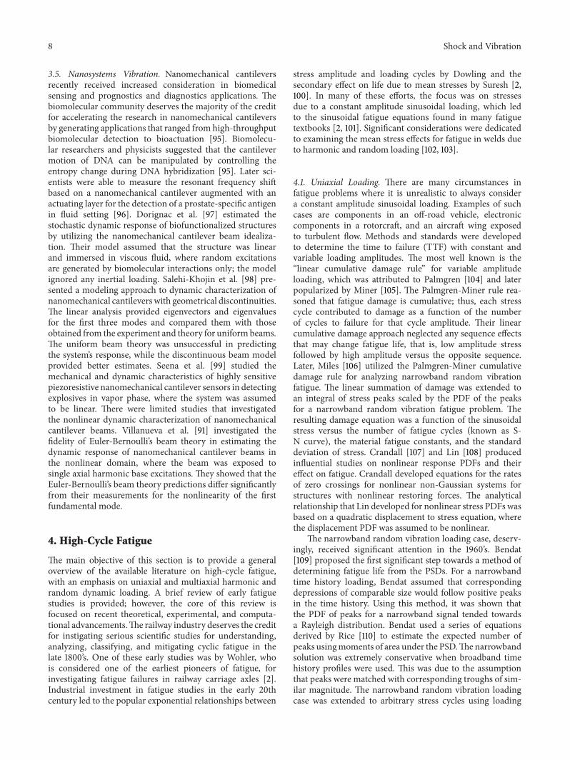
The typical product development approach is an iterativecycle known as design-prototype-test-fix [45]. Unfortunately,this process is time consuming and requires expensive phys-ical prototyping and testing. The lack of reliability predictioncapability of a product leads to deficiency in its develop-ment. To overcome this impediment, the design-prototype-test-fix approach was greatly modified in the electronicsindustries, with the introduction of high accelerated lifetesting (HALT) methodology during the prototyping andqualification stages. This can be accomplished by utilizinga HALT shaker table/chamber, shown in Figure 5. A typicalHALT chamber has a broad frequency spectrum between 10and 10 kHz and runs from 1 to 150Grms. The intent of HALTis to accelerate the failures in electronic devices by applying ahigher than normal stress to failure while assessing the design
Shock and Vibration 11
Figure 5: High accelerated life testing (HALT) chamber [15].
robustness through rigorous root cause failure analyses. Thebasic idea of HALT is to produce repetitive shocks to theshaker table using multiple pneumatic actuators at differentlocations of the table, thus producingmultiaxial energy.Thus,the device under test is exposed to uncontrolled broadbandmultiaxial random excitation, with the exception of the RMSacceleration value. Furthermore, the HALT chambers arecapable of exposing the test article to thermal stresses, and insome cases to humidity while it is under vibration. Designersand quality engineers have utilized HALT testing to exposedesign weaknesses that would eventually emerge as fieldfailures [14].
Unfortunately, HALT provides only a qualitative ratherthan a quantitative understanding of the failure modes andmechanisms due to two limitations [14]. First, the onlyacceleration input to the actuators that can be controlled is anacceleration RMS, Grms; thus, the only excitation that can beachieved is a quasirandom vibration.The second limitation isthe fact that HALT uses pneumatic actuators; consequently,it is impossible to control the energy input to each axisindividually. Due to these limitations, it is nearly impossibleto ascertain the most dominant failure mode or the axial loadthat initiates the damage. It is also impossible to preciselycorrelate structural failure during HALT to life-cycle seen inthe field.
Due to the limitations of single axis electrodynamicshakers, hydraulic actuators, and HALT shakers, researchersare currently investigating the utility of multiaxial electro-dynamic shakers to understand the response of structuresexposed tomultiaxial vibrations and subsequently the failuresdue to these complex dynamics. However, studies evaluatingthe merits of multiaxial vibration testing using multiaxialelectrodynamic shakers are very limited. This deficit isattributed to high cost constraints associated with theseshakers. Only a few investigators such as Whiteman andBurman [10, 13], French et al. [12], Gregory et al. [132],and Ernst et al. [49] have pointed out the shortcomingsof the sequential single axis vibration method. They havealso reported evidence of differences in failure modes andfatigue life for multiaxial loadings versus single-axis inputsby utilizing multiaxial electrodynamic shakers. These studiesare discussed in detail below.
Some of the limited work performed using multiaxialshakers was by Fullekrug [133], who characterized the modalresponse in the frequency and time domains of a struc-ture under base excitation using a hydraulic shaker thathad limited frequency range from 0 to 120Hz. Fullekrugdeveloped kinematic relationships between loads at the base
x
y
z
9.525mm
250mm
25mm
25mm
Blow-up of notch
Not to scale
Smoothnotchfinish
Notch radius =2.35mm ± 0.3mm
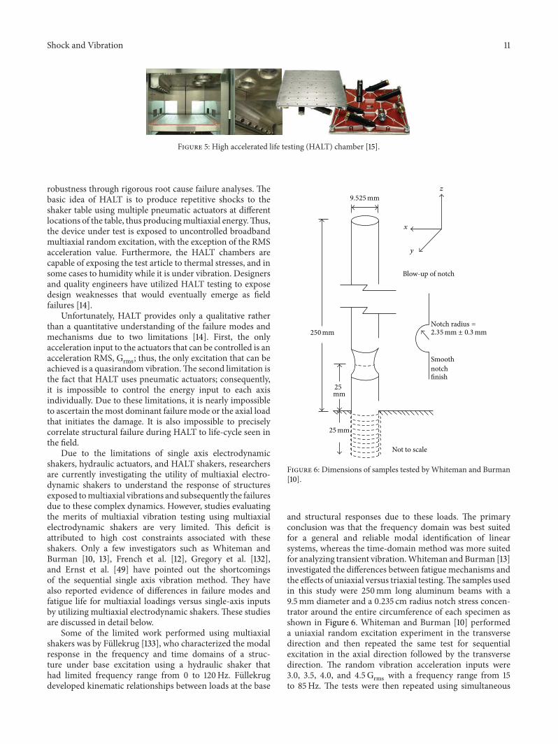
Figure 6: Dimensions of samples tested by Whiteman and Burman[10].
and structural responses due to these loads. The primaryconclusion was that the frequency domain was best suitedfor a general and reliable modal identification of linearsystems, whereas the time-domain method was more suitedfor analyzing transient vibration.Whiteman and Burman [13]investigated the differences between fatigue mechanisms andthe effects of uniaxial versus triaxial testing.The samples usedin this study were 250mm long aluminum beams with a9.5mm diameter and a 0.235 cm radius notch stress concen-trator around the entire circumference of each specimen asshown in Figure 6. Whiteman and Burman [10] performeda uniaxial random excitation experiment in the transversedirection and then repeated the same test for sequentialexcitation in the axial direction followed by the transversedirection. The random vibration acceleration inputs were3.0, 3.5, 4.0, and 4.5Grms with a frequency range from 15to 85Hz. The tests were then repeated using simultaneous

12 Shock and Vibration
1.25 in
1.75 in
Figure 7: Dimensions of samples tested by French et al. and test setup [12].
triaxial excitation. It was found that the excitation in the axialdirection did not weaken the specimens; on the contrary, itincreased the samples’ fatigue life. Whiteman and Burman[10] believed that work or strain hardening took place duringthe axial excitation portion of the second set of tests, whichincreased the fatigue failure resistance in the transversedirection. In the triaxial vibration experiments, the stressesthat eventually caused fatigue failure were predominantly inthe axial direction. However, simultaneous triaxial excitationaccelerated the crack initiation more rapidly. By comparison,the TTF for the single axis experiments was appreciablylonger than the triaxial experiments for the same input energylevel.
French et al. [12] performed durability experiments onnotched beam specimens using both sequential uniaxialand simultaneous biaxial testing on a TEAM tensor triaxialshaker, which was electrodynamically driven. The specimenswere 19 × 0.25 × 0.25 in3 aluminum beams with notcheslocated at two adjoining sides of the beam, as shown inFigure 7. One notch was normal to a transverse excitation(x-direction) while the other notch was normal to theother transverse excitation (y-direction). The notches wereintroduced to act as stress concentrators with depth of 0.08in. The notch normal to y-direction was 0.5 in above thenotch normal to the x-direction, as shown in Figure 7. Thebase excitation signal was a sine chirp from 10 to 35Hzover 30 s. The peak-to-peak acceleration amplitude was heldconstant at 4G. The sequential uniaxial and simultaneousbiaxial experiments produced different TTF, different failuredistributions, and different failure modes. French et al.concluded that sequential uniaxial testing generally takeslonger time to conduct than simultaneous multiaxial testing.Furthermore, the results from the sequential uniaxial testingare prone to produce questionable results. Unfortunately,the bandwidth in this study was limited and inapplicable torealistic structures.
At Sandia National Laboratories, Gregory et al. [132]investigated the prospect of using a six-DoF multiaxial elec-trodynamic shaker, developed by TEAM Inc., to illustrate theimportance of multiaxial excitations in performing realistictests. Dynamic characterization experiments were performedin uniaxial and multiaxial modes to compare the responsesof a structure under the different loadings with bandwidthof 10–2000Hz. The specimen used for this experiment wasa short rectangular aluminum beam with a lumped massmounted at the tip, as shown in Figure 8. Acceleration PSD
Figure 8: Simple structure under multiaxial loads [132].
input level of 0.0032G2/Hz was chosen to yield an overalllevel of 2.5 Grms for the X, Y, and Z translations. A spectralFEM model of the structure was constructed to investigatethe differences in the calculated vonMises stresses. Accordingto Gregory et al., the control system was configured for afull six-DoF random vibration input from 20 to 2000Hzwith zero coherence between the inputs. The experiment wasthen configured for uniaxial translation for each DoF. ThePSD levels were selected to be the same as for the previoussix-DoF tests to allow comparison of responses for uniax-ial versus multiaxial excitations. The experimental resultsshowed significant differences in the acceleration responseof the mass as well as the strain measured in the beam.The modal participations were different for the multiaxialexperiment, and the resulting instantaneous stresses andaccelerations states were different, not only in magnitude,but also in location and direction. This indicated that thepotential failure modes would be different.
6. Mapping Dynamic Loads to Fatigue
Some fatigue specialists maintain that the stress levels causedby vibration are usually too low to contribute to fatiguedamage and that fatigue cracks start because of higher stressespresent in the loading history [2]. It is also commonly knownthat the substantial number of stress cycles produced by high-frequency excitations can considerably contribute to fatiguedamage and may cause failure without reaching high loadlevels [5, 134]. Special analysis is often required in thesesituations since the vibration data is not in a form thatcan be used directly in a common fatigue damage model

Shock and Vibration 13
Modalanalysis
Estimate vibrationdurability and
damage accumulation
Detailed local FEA analysis
FEA global modal analysis
Structuraldynamicanalysis
Characterization of PWB andcomponents response
Freq. (Hz)
Strain history under randomexcitation
Time (s)
Stra
in
Design of test vehicle and fixture
Calibratemodel
Used to design andinstrument
Comp
PWBX = 186Y = 915m
500
1.00
021.0 525
G
PWB
Figure 9: Approach for mapping dynamic loads to fatigue [136].
such as the Palmgren-Miner rule. A common approachin mapping stationary random dynamic loads to fatigueis through performing a summation of all modal spectraldensities and determining the response standard deviationsin a broadband frequency range, covering all resonance fre-quencies of the structure within broadband frequency range.The modal cross-spectral densities are typically neglected[135]. Nonetheless, Dahlberg states that lightly damped struc-tures with well-separated fundamental frequencies are nota sufficient reason to neglect modal cross-spectral densitieseven if the random excitation of the structure is broadbandwhere several modes of the structure are excited [135].
To accurately estimate multiaxial vibration durability anddamage accumulation, the dynamics response model of thestructure must be coupled with experimental data, as illus-trated in Figure 9 [136]. This approach requires an iterativeand arduous development. The reason for this is that thereaction forces and vibration velocities in complex structuresdepend not only on the strength of excitation, but alsoon the coupling between structures and their components,as shown in Figure 9. The computational and experimentalcoupling is necessary since the FEM cannot model structuresadequately up to midfrequency range due to the highermodal density. The experimental tasks provide FRF dynamiccharacterization of the structure and its components as wellas time history data. A more practical approach is to utilizethe experimental FRF data to represent the structure andthen combine it with the FEM models as shown in Figure 9.However, this approach is not applicable if the structure isexposed to high amplitude excitation that could generatenonlinear behavior. Thus, the time history data must be
combined with the FEM models. This approach is intendedto yield accurate results but is time consuming to set up andis computationally expensive.
Currently, the Center for Advanced Life Cycle Engi-neering (CALCE) at the University of Maryland and theUS Army Research Laboratory (ARL) are investigating theutility of multiaxial electrodynamic shakers. The objectiveis to study the differences in failure modes and fatiguelife for multiaxial versus single-axial excitations by utilizingmultiaxial electrodynamic shakers. The multiaxial electrody-namic shaker used for this study was developed by TEAMInc. It consists of eight plane actuators and four out-of-plane actuators underneath the shaker table, as shown inFigure 1.The twelve electrodynamic shakers aremechanicallycoupled to the table. This architecture allows the shaker toproduce a true six-DoF vibration environment. Each axis hasfour shakers with 200 lbf rotation per axis. The excitationlimit is up to 30Gs with 0–3000Hz. The objective is toestablish a quantitative and qualitative relationship betweencomplex random multiaxial dynamic loading and the failuremechanisms. In this study, CALCE performed two sets ofthree random excitation experiments on CCAs. The firstset was for low amplitude broadband stationary randomexcitations, which consisted of the following single-axis in-plane, single-axis out-of-plane and combined in-plane andout-of-plane excitations. Each CCA was clamped along thetwo short edges while it was free along the two long edges,as shown in Figure 10. The CCA contained six large heavyinductors with high center of mass and with high standoff, asshown in Figure 10. Each inductor was attached to the CCAvia two leads to instigate bending motion in the in-plane

14 Shock and Vibration
X
Y
Fixed boundaries
L1 L2 L3
L4 L5 L6
1 2 3
4 5 6
Figure 10: CCA with six large inductors, dimensions are in inches.
Out-of-plane (Z) In-plane (X) Superposition Combined(Coh = 0.0)
500
450
400
350
300
250
200
150
100
50
0
Acce
lera
tion
resp
onse
(g2/H
z)×10
−3
Acceleration input:
0.0025 g2/Hz; 0.78Grms
Test orientation
Figure 11: Component 2 acceleration response in the x-direction0.78Grms.
direction and a gyroscopic motion. In the first set of tests,the excitation was a uniform broadband random stationaryprofile at low PSD acceleration input of 0.0025 g2/Hz and0.78Grms.
The acceleration responses of the middle component forthe three different excitations mentioned above are shown inFigure 11 and compared to the superposition technique. Thesame sets of tests were repeated for higher PSD accelerationinput of 0.04 g2/Hz and 3.14Grms. The acceleration responsesin the in-plane direction (X) of the middle component forthe three different excitations mentioned above are shown inFigures 11 and 12 and compared to the superposition tech-nique. Figures 11 and 12 show the component response due tomultiaxial excitations is equivalent to the linear superpositionof corresponding uniaxial responses. Furthermore, as theacceleration input increases, the deviation between the actualcomponent response due to multiaxial vibration and thelinear superposition of uniaxial responses increases as well.This deviation may be justified based on three reasons. First,the modal participation and nonlinear interactions betweencomponents and PWB could be the major contributors to
Out-of-plane (Z) In-plane (X) Superposition Combined
Acceleration input:0.04 g2/Hz; 3.14
4.0
3.5
3.0
2.5
2.0
1.5
1.0
0.5
0.0
Acce
lera
tion
resp
onse
(g2/H
z)
Grms
Figure 12: Component 2 acceleration response in the x-direction at3.14Grms.
this deviation. Second, the geometry of each componentmay create gyroscopic forces, which are proportional to thevelocities consistent with viscous damping forces; however,they are conservative forces [137]. Finally, the material non-linearity of the PWB and the solder joints may augmentthe drastic difference in TTF between multiaxial excitationsand sequential uniaxial superposition, as shown in Figure 13.Further studies are needed to quantify these contributions.
The fatigue damage in the components’ interconnectssite, shown in Figure 14, is due to a combination of flexuraldeformations in PCBs and inertial forces (translation andgyroscopic motions). The inertial forces are generated by themass of large/heavy components with high standoff. Thus,simultaneous multiaxial vibration may have the potentialto generate higher stresses through nonlinear cross-axisinteractions at the component level.
In this study, the change of the natural frequencies ofa middle component (L5) and an edge component (L1)were monitored during the experiments mentioned above.Ernst et al. [49] showed that the frequencies shifted linearlyacross all components under single axial and biaxial vibrationconditions, as shown in Figure 15. Ernst et al. assumedthat this shift corresponded to fatigue crack growth inthe component lead shown in Figure 14. Their results alsorevealed that natural frequency was lower when the CCA

Shock and Vibration 15
0.0E + 0
5.0E − 5
1.0E − 4
1.5E − 4
2.0E − 4
2.5E − 4
3.0E − 4
3.5E − 4
Out-of-plane (Z) In-plane (X) Superposition Combined(Coh = 0.0)
Dam
age a
ccum
ulat
ion
rate
(1/s
)
Acceleration input:0.04 g2/Hz; 3.14Grms
Test orientation
Figure 13: Component 2 damage accumulation rate at 3.14Grms.
was exposed to multiaxial excitation, but they indicated thatfurther investigation is needed to verify this phenomenon.Ernst et al. proposed using this approach as a possiblemethodfor failure prognostics and prediction for the components’remaining life. This approach has been observed in currentstudies exploring methods for improving accelerated fatiguetesting by simultaneously monitoring the modal parametersof critical components [138–142].
7. Future Directions
Based on the literature review and interaction with gov-ernment agencies, industries, and academia, the authorsrecognized three major thrust areas for continued researchand deployment: modeling and simulation, experimental andtesting, and standards and procedures updating.These thrustareas are summarized in Figure 16. As mentioned above,several closed-form solutions and computational modelswere developed to approximate the response and fatiguelife of linear and nonlinear structures exposed to complexvibration loading. Most of these models are based on uniqueapproximations and can only be applied to specific loadingand boundary conditions. Some of these loading conditionswere not possible to duplicate in a laboratory environmentprior to the introduction of the multiaxial electrodynamicshaker capable of producing rotational degrees of freedoms.This capability is opening a plethora of opportunities tovalidate and update existing multibodies and flexible-bodiesdynamic models and produce new realistic models to ade-quately approximate the response of structures and subse-quently their remaining life. Analysts may be able to movebeyond the laborious approach of conducting explicit FEManalysis calibrated with suspect transfer functions obtainedfrom sequential testing, then following it by another explicitanalysis based on time history data and comparing the strainresults to those from testing. There might be a possibilityfor developing spectral FEM models to avoid using thecumbersome and expensive explicit FEM.
Figure 14: Component L2 failure due to in-plane and out-of-planeexcitations at 3.14Grms.
As shown above, CALCE/ARL has shown that simultane-ous multiaxial vibration may have the potential to generatehigher stresses through nonlinear cross-axis interactionsat the component level. This was possible because of thecapabilities that the MDoF electrodynamic shaker was ableto provide. However, generating the loads for differentcomplex operational conditions and tracking the structuralresponse of critical components require significant signalprocessing, data reduction, and real-time computation ofthe inputs/outputs. Stochastic models may potentially beupdated as a result of the coherent/incoherent multiaxialrandom vibration excitation that can be achieved with theMDoF electrodynamic technology. Accelerated test factorsare currently incorporated in the MIL-STF-810G combinedwith exaggeration factors to provide conservatism in theuniaxial test schedules. Multiaxial vibration studies mayprovide insights into whether these factors are reasonableor not and provide new guidelines for accelerated life test-ing using MDoF technologies. Furthermore, the design forprognostic and diagnostics, structural health managementand condition-based maintenance may be enhanced andruggedized through real-world multiaxial dynamics labora-tory simulations.
8. Conclusion
It can be concluded from this literature review that itis essential to understand the structural characteristics ofdevices in order to correlate the defects with the dynamicresponses. As mentioned above, the main challenge in struc-tural systems is the prediction of the reliability and lifetimeof the critical components. Therefore, it is imperative toidentify the failure mechanisms of the components throughadequate computational and experimental analyses. How-ever, the experimental and computational approaches mustemulate the real-world operational conditions, which includesimulating MDoF dynamic loads. This involves estimatingandmeasuring the transient multiaxial displacements, whichcan be accomplished with the aid of a multiaxial shaker.
Establishing the relationship between different flexiblestructures formulations is an important issue since there isa need to clearly define the assumptions and approximationsunderlying each formulation.This may allow for establishingguidelines and criteria that define the limitations of eachapproach used in flexible structures dynamics. This taskcan now be accomplished by utilizing multiaxial vibrationcapability, which is making it possible to perform the

16 Shock and Vibration
90
85
80
75
70
65
60
55
50
450 20 40 60 80 100
Damage accumulation (%)
In-plane comp 1
In-plane comp 5
Combined comp 1
Out-of-plane comp 1
y = −5.7x + 81.9
y = −4.5x + 81.0
y = −3.9x + 74.1
y = −5.4x + 71.9
Mod
e1na
tura
l fre
quen
cyof
com
pone
nt (H
z)
5%–95% trend comp. 1 in-plane5%–95% trend comp. 5 in-plane5%–95% trend comp. 1 combined5%–95% trend comp. 1 out-of-plane
Figure 15: Change in the natural frequency as a function of damage accumulation [49].
Modeling andsimulation
Experimentaland testing
Standards andprocedures
Closed formsolutions
ExplicitFEA
SpectralFEA
LinearNonlinear
Experientialmodels
Stochasticin/output
SignalDatareduction
Correctionfactors
Accelerationfactor
Superposition
Benchmark
Figure 16: Research areas and potential gaps.
CALCE/ARL joint research efforts to study large deformationof flexible systems exposed to multiaxial excitations.
Conflict of Interests
The authors declare that there is no conflict of interestsregarding the publication of this paper.
Acknowledgments
This work was accomplished via the Collaborative Researchand Development Agreement (CRADA) between the USArmy Research Laboratory and the University of Maryland,College Park, and the continual support of TEAM Inc. andDataPhysics Inc. The authors thank the sponsors of the
Center for Advanced Life Cycle Engineering (CALCE) forproviding access to the MDoF shaker facility.
References
[1] J. E. Shigley and C. R. Mischke,Mechanical Engineering Design,McGraw-Hill, Boston, Mass, USA, 6th edition, 2001.
[2] N. E. Dowling, Mechanical Behavior of Materials: EngineeringMethods for Deformation, Fracture, and Fatigue, Prentice Hall,Upper Saddle River, NJ, USA, 2nd edition, 1999.
[3] I. Elishakoff, “Generalized eringen problem: influence of axialforce on random vibration response of simply supported beam,”Structural Safety, vol. 4, no. 4, pp. 255–265, 1987.
[4] C. Leser, L. Juneja, S. Thangjitham, and N. E. Dowling, “Onmulti-axial random fatigue load modeling,” SAE TechnicalPaper 980696, Society of Automotive Engineering, 1996.
Shock and Vibration 17
[5] Y. Liu and S. Mahadevan, “Multiaxial high-cycle fatigue cri-terion and life prediction for metals,” International Journal ofFatigue, vol. 27, no. 7, pp. 790–800, 2005.
[6] X. Pitoiset, A. Preumont, andA. Kernilis, “Tools for amultiaxialfatigue analysis of structures submitted to random vibra-tions,” in Proceedings of the European Conference on SpacecraftStructures Materials and Mechanical Testing, Braunschweig,Germany, November 1998.
[7] D. J. Segalman, C. W. G. Fulcher, G. M. Reese, and R. V. FieldJr., “Efficient method for calculating r.m.s. von Mises stressin a random vibration environment,” Journal of Sound andVibration, vol. 230, no. 2, pp. 393–410, 2000.
[8] D. Socie and G. Marquis, Multiaxial Fatigue, Society of Auto-motive Engineers, Warrendale, Pa, USA, 2000.
[9] K. A. Sweitzer, Random Vibration Response Statistics for FatigueAnalysis of Nonlinear Structures [Ph.D. thesis], University ofSouthampton, Southampton, UK, 2006.
[10] W. E. Whiteman and M. S. Berman, “Fatigue failure resultsfor multi-axial versus uniaxial stress screen vibration testing,”Shock and Vibration, vol. 9, no. 6, pp. 319–328, 2002.
[11] M. Paulus, A. Dasgupta, and E. Habtour, “Life estimationmodelof a cantilevered beam subjected to complex random vibration,”Fatigue and Fracture of Engineering Materials and Structures,vol. 35, no. 11, pp. 1058–1070, 2012.
[12] R. M. French, R. Handy, and H. L. Cooper, “A comparisonof simultaneous and sequential single-axis durability testing,”Experimental Techniques, vol. 30, no. 5, pp. 32–37, 2006.
[13] W. E. Whiteman and M. Berman, “Inadequacies in uniaxialstress screen vibration testing,” Journal of the Institute ofEnvironmental Sciences and Technology, vol. 44, no. 4, pp. 20–23, 2001.
[14] E. Habtour, C. Choi, G. Drake, A. Dasgupta, and M. Al-Bassyiouni, “Improved reliability testing with multiaxial elec-trodynamics vibration,” in Proceedings of the 56th AnnualReliability andMaintainability Symposium, San Jose, Calif, USA,2010.
[15] E. Habtour, C. Choi, M. Osterman, and A. Dasgupta, “Novelapproach to improve electronics reliability in the next gen-eration of US army small unmanned ground vehicles undercomplex vibration conditions,” Journal of Failure Analysis andPrevention, vol. 12, no. 1, pp. 86–95, 2012.
[16] C. J. Dodds and C. H. Ward, “The ubiquitous four-poster,”Engineering Integrity Society, vol. 16, no. 1, pp. 17–23, 2005.
[17] C. M. Awate, S. M. Panse, and C. J. Dodds, “Validation of anaccelerated test on a four-post road simulator,” Paper 2007-26-070, Society of Automotive Engineering, pp. 761–767, 2007.
[18] C. J. Dodds andA. R. Plummer, “Laboratory road simulation forfull vehicle testing a review,” in Proceedings of the Symposium onInternational Automotive Technology, 2001.
[19] J. C. Delamotte, R. F. Nascimento, and J. R. F. Arruda, “Simplemodels for the dynamic modeling of rotating tires,” Shock andVibration, vol. 15, no. 3-4, pp. 383–393, 2008.
[20] C. Q. Liu, “Combination of an improved FRF-based substruc-ture synthesis and power flow method with application tovehicle axle noise analysis,” Shock and Vibration, vol. 15, no. 1,pp. 51–60, 2008.
[21] N.W.M.Bishop, “Vibration fatigue analysis in the finite elementenvironment,” in Proceedings of the 16th Encuentro del GrupoEspanol de Fractura, Torremolinos, Spain, 1999.
[22] M. H. A. Bonte, A. De Boer, and R. Liebregts, “Prediction ofmechanical fatigue caused by multiple random excitations,” in
Proceedings of the ISMA Conference, pp. 697–708, September2004.
[23] M. H. A. Bonte, A. de Boer, and R. Liebregts, “Determining thevon Mises stress power spectral density for frequency domainfatigue analysis including out-of-phase stress components,”Journal of Sound and Vibration, vol. 302, no. 1-2, pp. 379–386,2007.
[24] P. H. Wirsching, T. L. Paez, and K. Ortiz, Random Vibrations:Theory and Practice, JohnWiley and Sons, New York, NY, USA,1995.
[25] T. Dirlik, Application of Computers in Fatigue Analysis [Ph.D.thesis], University of Warwick, Warwick, UK, 1985.
[26] D. A.Thomas, K. Avers, andM. Pecht, “The “trouble not identi-fied” phenomenon in automotive electronics,” MicroelectronicsReliability, vol. 42, no. 4-5, pp. 641–651, 2002.
[27] D. H. Hodges and G. A. Pierce, Introduction to StructuralDynamics and Aeroelasticity, 2nd edition, 2011.
[28] J. M. Sater, C. R. Crowe, R. Antcliff, and A. Das, “An assess-ment of smart Air and space structures: demonstrations andtechnology,” IDAReport P-3552, Log:H 00-002035, Institute forDefense Analysis, Alexandria, Va, USA, 2000.
[29] M. R. M. C. Da Silva, “Non-linear flexural-flexural-torsional-extensional dynamics of beams-I. Formulation,” InternationalJournal of Solids and Structures, vol. 24, no. 12, pp. 1225–1234,1988.
[30] M. R. M. Crespo Da Silva and C. L. Zaretzky, “Nonlinearflexural-flexural-torsional interactions in beams including theeffect of torsional dynamics. I: primary resonance,” NonlinearDynamics, vol. 5, no. 1, pp. 3–23, 1994.
[31] E. H. Dowell, “Damping in beams and plates due to slipping atthe support boundaries,” Journal of Sound and Vibration, vol.105, no. 2, pp. 243–253, 1986.
[32] D.H.Hodges and E.H.Dowell, “Nonlinear equations ofmotionfor the elastic bending and torsion of twisted nonuniform rotorblades,” NASA Technical Notes NASA TN D-7818, 1974.
[33] D. S. Whithead, “The analysis of blade vibration due to randomexcitation,” Tech. Rep. 3253, United KingdomMinistry of Avia-tion: Aeronautical Research Council Reports and Memoranda,London, UK, 1960.
[34] M. Aykan and M. Celik, “Vibration fatigue analysis and multi-axial effect in testing of aerospace structures,” MechanicalSystems and Signal Processing, vol. 23, no. 3, pp. 897–907, 2009.
[35] G. V. Chary, E. Habtour, and G. S. Drake, “Improving thereliability in the next generation of US army platforms throughphysics of failure analysis,” Journal of Failure Analysis andPrevention, vol. 12, no. 1, pp. 75–58, 2012.
[36] Y. Zhou, M. Al-Bassyiouni, and A. Dasgupta, “Vibration dura-bility assessment of sn3.0ag0.5cu and sn37pb solders underharmonic excitation,” Journal of Electronic Packaging, vol. 131,no. 1, 2009.
[37] J. H. Lau, Solder Joint Reliability, Theory and Applications, VanNostrand Reinhold, New York, NY, USA, 1990.
[38] J. Lau, K. Gratalo, E. Schneider, T. Marcotte, and T. Baker,“Solder joint reliability of large plastic ball grid array assembliesunder bending, twisting, and vibration conditions,” CircuitWorld, vol. 22, no. 1, pp. 27–32, 1995.
[39] J. H. Lau and P. Yi, Solder Joint Reliability, of BGA, CSP, Flip Chipand Fine Pitch SMT Assemblies, McGraw-Hill, New York, NY,USA, 1997.
[40] X. Liu, V. K. Sooklal, M. A. Verges, and M. C. Larson,“Experimental study and life prediction on high cycle vibration
18 Shock and Vibration
fatigue in BGA packages,” Microelectronics Reliability, vol. 46,no. 7, pp. 1128–1138, 2006.
[41] X. Yang, Y. Luo, and Q. Gao, “Constitutive modeling ontime-dependent deformation behavior of 96.5Sn-3.5Ag solderalloy under cyclic multiaxial straining,” Journal of ElectronicPackaging, vol. 129, no. 1, pp. 41–47, 2007.
[42] Y. Zhou, M. Al-Bassyiouni, and A. Dasgupta, “Harmonic andrandom vibration durability of SAC305 and Sn37Pb solderalloys,” IEEE Transactions on Components and Packaging Tech-nologies, vol. 33, no. 2, pp. 319–328, 2010.
[43] J. Gu, D. Barker, and M. Pecht, “Prognostics implementation ofelectronics under vibration loading,” Microelectronics Reliabil-ity, vol. 47, no. 12, pp. 1849–1856, 2007.
[44] D. B. Barker, Y. S. Chen, andA.Dasgupta, “Estimating the vibra-tion fatigue life of quad leaded surface mount components,”Journal of Electronic Packaging, vol. 115, no. 2, pp. 195–200, 1993.
[45] R. S. Li, “A methodology for fatigue prediction of electroniccomponents under randomvibration load,” Journal of ElectronicPackaging, vol. 123, no. 4, pp. 394–400, 2001.
[46] E. Martynenko, W. Zhou, A. Chudnovsky, R. S. Li, and L.Poglitsch, “High cycle fatigue resistance and reliability assess-ment of flexible printed circuitry,” Journal of Electronic Packag-ing, vol. 124, no. 3, pp. 254–259, 2002.
[47] S. Mathew, D. Das, M. Osterman, M. Pecht, R. Ferebee, andJ. Clayton, “Virtual remaining life assessment of electronichardware subjected to shock and random vibration life cycleloads,” Journal of the Institute of Environmental Sciences andTechnology, vol. 50, no. 1, pp. 86–97, 2007.
[48] S. Shetty, V. Lehtinen, A. Dasgupta, V. Halkola, and T.Reinikainen, “Fatigue of chip scale package interconnects dueto cyclic bending,” Journal of Electronic Packaging, vol. 123, no.3, pp. 302–308, 2001.
[49] M. Ernst, C. Choi, A. Dasgupta, and E. Habtour, “Physics offailure models for multiaxial vibration fatigue in electronicsassemblies,” in Proceedings of the Accelerated Stress Testing andReliability Workshop, Ontario, Canada, 2012.
[50] A. C. Eringen, “Response of beams and to random loads,”Journal of Applied Mechanics, vol. 24, pp. 46–52, 1957.
[51] R. E. Herbert, “Random vibrations of a nonlinear elastic beam,”Journal of the Acoustical Society of America, vol. 36, no. 11, pp.2090–2094, 1964.
[52] I. Elishakoff and D. Livshits, “Some closed-form solutionsin random vibration of Bernoulli-Euler beams,” InternationalJournal of Engineering Science, vol. 22, no. 11-12, pp. 1291–1301,1984.
[53] I. Elishakoff, J. Fang, and R. Caimi, “Random vibration of anonlinearly deformed beam by a new stochastic linearizationtechnique,” International Journal of Solids and Structures, vol.32, no. 11, pp. 1571–1584, 1995.
[54] R. A. Ibrahim and R. J. Somnay, “Nonlinear dynamic analysis ofan elastic beam isolator sliding on frictional supports,” Journalof Sound and Vibration, vol. 308, no. 3–5, pp. 735–757, 2007.
[55] C.-H. Ho, R. A. Scott, and J. G. Eisley, “Non-planar, non-linearoscillations of a beam-I. Forced motions,” International Journalof Non-Linear Mechanics, vol. 10, no. 2, pp. 113–127, 1975.
[56] C.-H. Ho, R. A. Scott, and J. G. Eisley, “Non-planar, non-linearoscillations of a beam II. Free motions,” Journal of Sound andVibration, vol. 47, no. 3, pp. 333–339, 1976.
[57] M. R. M. Crespo da Silva and C. C. Glynn, “Nonlinearflexural-flexural-torsional dynamics of inextensional beams. I:equations ofmotion,” Journal of StructuralMechanics, vol. 6, no.4, pp. 437–448, 1978.
[58] M. R. M. Crespo de Silva and C. C. Glynn, “Nonlinear flexural-flexural-torsional dynamics of inextensional beams. II: forcedmotions,” Journal of Structural Mechanics, vol. 6, no. 4, pp. 449–461, 1978.
[59] M. R. M. C. Da Silva, “Non-linear flexural-flexural-torsional-extensional dynamics of beams-II. Response analysis,” Interna-tional Journal of Solids and Structures, vol. 24, no. 12, pp. 1235–1242, 1988.
[60] A. H. Nayfeh and P. F. Pai, “Non-linear non-planar parametricresponses of an inextensional beam,” International Journal ofNon-Linear Mechanics, vol. 24, no. 2, pp. 139–158, 1989.
[61] P. F. Pai and A. H. Nayfeh, “Non-linear non-planar oscillationsof a cantilever beam under lateral base excitations,” Interna-tional Journal of Non-Linear Mechanics, vol. 25, no. 5, pp. 455–474, 1990.
[62] C. L. Zaretzky and M. R. M. Crespo da Silva, “Nonlinearflexural-flexural-torsional interactions in beams including theeffect of torsional dynamics. II: combination resonance,” Non-linear Dynamics, vol. 5, no. 2, pp. 161–180, 1994.
[63] H. N. Arafat, A. H. Nayfeh, and C.-M. Chin, “Nonlinear non-planar dynamics of parametrically excited cantilever beams,”Nonlinear Dynamics, vol. 15, no. 1, pp. 31–61, 1998.
[64] A. H. Nayfeh and H. N. Arafat, “Investigation of subcom-bination internal resonances in cantilever beams,” Shock andVibration, vol. 5, pp. 289–296, 1998.
[65] A. H. Nayfeh and H. N. Arafat, “Nonlinear response of can-tilever beams to combination and subcombination resonances,”Shock and Vibration, vol. 5, no. 5-6, pp. 277–288, 1998.
[66] H. N. Arafat, Nonlinear Dynamic Analysis of Cantilever Beam[Ph.D. thesis], Virginia Polytechnic Institute and State Univer-sity, Blacksburg, Va, USA, 1999.
[67] J. R. Banerjee, “Explicit analytical expressions for frequencyequation and mode shapes of composite beams,” InternationalJournal of Solids and Structures, vol. 38, no. 14, pp. 2415–2426,2001.
[68] P. Malatkar and A. H. Nayfeh, “On the transfer of energybetweenwidely spacedmodes in structures,”Nonlinear Dynam-ics, vol. 31, no. 2, pp. 225–242, 2003.
[69] P.Malatkar andA.H. Nayfeh, “A parametric identification tech-nique for single-degree-of-freedom weakly nonlinear systemswith cubic nonlinearities,” Journal of Vibration and Control, vol.9, no. 3-4, pp. 317–336, 2003.
[70] P. Malatkar, Nonlinear Vibrations of Cantilever Beams andPlates [Ph.D. thesis], Virginia Polytechnic Institute and StateUniversity, Blacksburg, Va, USA, 2003.
[71] T. J. Anderson, B. Balachandran, and A. H. Nayfeh, “Nonlinearresonances in a flexible cantilever beam,” Journal of Vibrationand Acoustics, vol. 116, no. 4, pp. 480–484, 1994.
[72] J. Dugundji and V. Mukhopadhyay, “Lateral bending-torsionvibrations of a thin beam under parametric excitation,” Journalof Applied Mechanics, vol. 40, no. 3, pp. 693–698, 1973.
[73] D. M. Tang and E. H. Dowell, “Damping in beams and platesdue to slipping at the support boundaries. Part 2: numerical andexperimental study,” Journal of Sound and Vibration, vol. 108,no. 3, pp. 509–522, 1986.
[74] C. W. S. To, “Vibration of a cantilever beam with a baseexcitation and tip mass,” Journal of Sound and Vibration, vol.83, no. 4, pp. 445–460, 1982.
[75] M. P. Cartmell and J. W. Roberts, “Simultaneous combinationresonances in a parametrically excited cantilever beam,” Strain,vol. 23, no. 3, pp. 117–126, 1987.

Shock and Vibration 19
[76] B. Balachandran and A. H. Nayfeh, “Nonlinear motions ofbeam-mass structure,”Nonlinear Dynamics, vol. 1, no. 1, pp. 39–61, 1990.
[77] B. Balachandran and A. H. Nayfeh, “Observations of modalinteractions in resonantly forced beam-mass structures,” Non-linear Dynamics, vol. 2, no. 2, pp. 77–117, 1991.
[78] J.W. Jaworski and E.H.Dowell, “Free vibration of a cantileveredbeam with multiple steps: comparison of several theoreticalmethods with experiment,” Journal of Sound and Vibration, vol.312, no. 4-5, pp. 713–725, 2008.
[79] M. Ansari, E. Esmailzadeh, and N. Jalili, “Coupled vibrationand parameter sensitivity analysis of rocking-mass vibratinggyroscopes,” Journal of Sound and Vibration, vol. 327, no. 3–5,pp. 564–583, 2009.
[80] A. M. Wickenheiser, “Design optimization of linear and non-linear cantilevered energy harvesters for broadband vibrations,”Journal of IntelligentMaterial Systems and Structures, vol. 22, no.11, pp. 1213–1225, 2011.
[81] M. Ansari, E. Esmailzadeh, and N. Jalili, “Exact frequencyanalysis of a rotating cantilever beamwith tip mass subjected totorsional-bending vibrations,” Journal of Vibration and Acous-tics, vol. 133, no. 4, Article ID 041003, 2011.
[82] A. Erturk and D. J. Inman, “Parameter identification and opti-mization in piezoelectric energy harvesting: analytical relations,asymptotic analyses, and experimental validations,” Proceedingsof the Institution of Mechanical Engineers. Part I: Journal ofSystems and Control Engineering, vol. 225, no. 4, pp. 485–496,2011.
[83] A. Erturk, “Assumed-modes modeling of piezoelectric energyharvesters: euler-bernoulli, rayleigh, and timoshenko modelswith axial deformations,” Computers and Structures, vol. 106-107, pp. 214–227, 2012.
[84] M. Esmaeili, N. Jalili, and M. Durali, “Dynamic modeling andperformance evaluation of a vibrating beam microgyroscopeunder general support motion,” Journal of Sound and Vibration,vol. 301, no. 1-2, pp. 146–164, 2007.
[85] S. C. Stanton, C. C. McGehee, and B. P. Mann, “Nonlineardynamics for broadband energy harvesting: investigation of abistable piezoelectric inertial generator,” Physica D: NonlinearPhenomena, vol. 239, no. 10, pp. 640–653, 2010.
[86] C. P. Green and J. E. Sader, “Torsional frequency response ofcantilever beams immersed in viscous fluids with applicationsto the atomic force microscope,” Journal of Applied Physics, vol.92, no. 10, pp. 6262–6274, 2002.
[87] S. C. Stanton, A. Erturk, B. P. Mann, E. H. Dowell, and D. J.Inman, “Nonlinear nonconservative behavior and modeling ofpiezoelectric energy harvesters including proof mass effects,”Journal of IntelligentMaterial Systems and Structures, vol. 23, no.2, pp. 183–199, 2012.
[88] S. C. Stanton, B. A. M. Owens, and B. P. Mann, “Harmonicbalance analysis of the bistable piezoelectric inertial generator,”Journal of Sound and Vibration, vol. 331, no. 15, pp. 3617–3627,2012.
[89] H. J. R. Westra, D. M. Karabacak, S. H. Brongersma, M. Crego-Calama, H. S. J. Van Der Zant, and W. J. Venstra, “Interactionsbetween directly- and parametrically-driven vibration modesin a micromechanical resonator,” Physical Review B: CondensedMatter and Materials Physics, vol. 84, no. 13, Article ID 134305,2011.
[90] K. Wolf and O. Gottlieb, “Nonlinear dynamics of a cantileverbeam actuated by piezoelectric layers in symmetric and asym-metric configuration,” Tech. Rep. ETR-2001-02, Institute ofTechnology, Haifa, Israel, 2001.
[91] L. G. Villanueva, R. B. Karabalin, M. H. Matheny, D. Chi, J.E. Sader, and M. L. Roukes, “Nonlinearity in nanomechanicalcantilevers,” Physical Review B, vol. 87, Article ID 024304, 2013.
[92] V. Kumar, J. K. Miller, and J. F. Rhoads, “Nonlinear paramet-ric amplification and attenuation in a base-excited cantileverbeam,” Journal of Sound andVibration, vol. 330, no. 22, pp. 5401–5409, 2011.
[93] J. F. Rhoads,N. J.Miller, S.W. Shaw, andB. F. Feeny, “Mechanicaldomain parametric amplification,” Journal of Vibration andAcoustics, vol. 130, no. 6, Article ID 061006, 2008.
[94] S. F. Ali, S. Adhikari,M. I. Friswell, and S.Narayanan, “The anal-ysis of piezomagnetoelastic energy harvesters under broadbandrandom excitations,” Journal of Applied Physics, vol. 109, no. 7,Article ID 074904, 2011.
[95] G. Wu, H. Ji, K. Hansen et al., “Origin of nanomechanicalcantilever motion generated from biomolecular interactions,”Proceedings of the National Academy of Sciences of the UnitedStates of America, vol. 98, no. 4, pp. 1560–1564, 2001.
[96] K. S. Hwang, J. H. Lee, J. Park, D. S. Yoon, J. H. Park, and T. S.Kim, “In-situ quantitative analysis of a prostate-specific antigen(PSA) using a nanomechanical PZT cantilever,” Lab on a Chip:Miniaturisation for Chemistry and Biology, vol. 4, no. 6, pp. 547–552, 2004.
[97] J. Dorignac, A. Kalinowski, S. Erramilli, and P. Mohanty,“Dynamical response of nanomechanical oscillators in immis-cible viscous fluid for in Vitro biomolecular Recognition,”Physical Review Letters, vol. 96, no. 18, Article ID 186105, 2006.
[98] A. Salehi-Khojin, S. Bashash, and N. Jalili, “Modeling andexperimental vibration analysis of nanomechanical cantileveractive probes,” Journal ofMicromechanics andMicroengineering,vol. 18, no. 8, Article ID 085008, 2008.
[99] V. Seena, A. Fernandes, P. Pant, S. Mukherji, and V. RamgopalRao, “Polymer nanocomposite nanomechanical cantilever sen-sors: material characterization, device development and appli-cation in explosive vapour detection,” Nanotechnology, vol. 22,no. 29, Article ID 295501, 2011.
[100] S. Suresh, Fatigue of Materials, Cambridge University Press,Cambridge, UK, 2nd edition, 1998.
[101] D. Segalman, G. Reese, R. Field Jr., and C. Fulcher, “Estimatingthe probability distribution of von Mises stress for structuresundergoing random excitation,” Journal of Vibration and Acous-tics, vol. 122, no. 1, pp. 42–48, 2000.
[102] S. Sarkani, D. P. Kihl, and J. E. Beach, “Fatigue of weldedjoints under narrowband non-Gaussian loadings,” ProbabilisticEngineering Mechanics, vol. 9, no. 3, pp. 179–190, 1994.
[103] D. Radaj, C. M. Sonsino, and W. Fricke, Fatigue Assessmentof Welded Joints By Local Approaches, Woodhead PublishingLimited, Cambridge, UK, 2006.
[104] A. Z. Palmgren, “Die LebensdauerVonKugellagern,”ZeitschriytDes Vereines Der Deutschen Ingenioeren, vol. 68, pp. 339–341,1924.
[105] M. A.Miner, “Cumulative damage in fatigue,” Journal of AppliedMechanics, vol. 12, no. 3, pp. 159–164, 1945.
[106] J. W. Miles, “On structural fatigue under random loading,”Journal of the Aeronautical Sciences, vol. 21, no. 11, pp. 753–762,1957.

20 Shock and Vibration
[107] S. H. Crandall, “Zero crossings, peaks, and other statisticalmeasures of random responses,” Journal of the Acoustical Societyof America, vol. 35, no. 11, pp. 1693–1699, 1963.
[108] Y. K. Lin, “Probability distributions of stress peaks in linear andnonlinear structures,” AIAA Journal, vol. 1, no. 5, pp. 1133–1138,1963.
[109] J. S. Bendat, “Probability functions for random responses-prediction of peaks, fatigue damage, and catastrophic failures,”NASA CR-33, N64-17990, 1964.
[110] S. O. Rice, “Mathematical analysis of random noise,” SelectedPapers onNoise and Stochastic Processes,Dover,NewYork,NY,USA, 1954.
[111] N. W. M. Bishop, The Use of Frequency Domain Parameters toPredict Structural Fatigue [Ph.D. thesis], University of Warwick,1988.
[112] N. W. M. Bishop and F. Sherratt, “Theoretical solution for theestimation of “rainflow” ranges from power spectral densitydata,” Fatigue and Fracture of Engineering Materials and Struc-tures, vol. 13, no. 4, pp. 311–326, 1990.
[113] K.Upadhyayula andA.Dasgupta, “Physics-of-failure guidelinesfor accelerated qualification of electronic systems,” Quality andReliability Engineering International, vol. 14, no. 6, pp. 433–447,1998.
[114] E. Habtour, M. Paulus, and A. Dasgupta, “Modeling approachfor predicting the rate of frequency change of notched beamexposed to Gaussian random excitation,” Shock and Vibration,2013.
[115] Y. Lu, Random Vibration Analysis of Higher-Order NonlinearBeams and Composite Plates with Applications of ARMAModels[Ph.D. thesis], Virginia Polytechnic Institute and State Univer-sity, Blacksburg, Va, USA, 2008.
[116] T. Łagoda, E. Macha, and A. Niesłony, “Fatigue life calculationby means of the cycle counting and spectral methods undermultiaxial random loading,” Fatigue and Fracture of EngineeringMaterials and Structures, vol. 28, no. 4, pp. 409–420, 2005.
[117] X. Pitoiset and A. Preumont, “Spectral methods for multiaxialrandom fatigue analysis of metallic structures,” InternationalJournal of Fatigue, vol. 22, no. 7, pp. 541–550, 2000.
[118] X. Pitoiset, I. Rychlik, and A. Preumont, “Spectral methods toestimate local multiaxial fatigue failure for structures under-going random vibrations,” Fatigue and Fracture of EngineeringMaterials and Structures, vol. 24, no. 11, pp. 715–727, 2001.
[119] A. Carpinteri, E. Macha, R. Brighenti, and A. Spagnoli,“Expected principal stress directions under multiaxial randomloading. Part I: theoretical aspects of the weight functionmethod,” International Journal of Fatigue, vol. 21, no. 1, pp. 83–88, 1999.
[120] A. Carpinteri, R. Brighenti, E. Macha, and A. Spagnoli,“Expected principal stress directions under multiaxial ran-dom loading. Part II: numerical simulation and experimentalassessment through the weight function method,” InternationalJournal of Fatigue, vol. 21, no. 1, pp. 89–96, 1999.
[121] Y. Liu and S. Mahadevan, “A unified multiaxial fatigue damagemodel for isotropic and anisotropic materials,” InternationalJournal of Fatigue, vol. 29, no. 2, pp. 347–359, 2007.
[122] Y. Liu, Stochastic Modeling of Multiaxial Fatigue and Fracture[Ph.D. thesis], Vanderbilt University, Nashville, Tenn, USA,2006.
[123] S. Lambert, E. Pagnacco, and L. Khalij, “A probabilistic modelfor the fatigue reliability of structures under random loadingswith phase shift effects,” International Journal of Fatigue, vol. 32,no. 2, pp. 463–474, 2010.
[124] C. Braccesi, F. Cianetti, G. Lori, and D. Pioli, “An equivalentuniaxial stress process for fatigue life estimation of mechanicalcomponents under multiaxial stress conditions,” InternationalJournal of Fatigue, vol. 30, no. 8, pp. 1479–1497, 2008.
[125] C. Braccesi, F. Cianetti, G. Lori, and D. Pioli, “The frequencydomain approach in virtual fatigue estimation of non-linearsystems: the problem of non-Gaussian states of stress,” Interna-tional Journal of Fatigue, vol. 31, no. 4, pp. 766–775, 2008.
[126] G. Allegri and X. Zhang, “On the inverse power laws foraccelerated random fatigue testing,” International Journal ofFatigue, vol. 30, no. 6, pp. 967–977, 2008.
[127] Z. Lei and C. Qiu, “A dynamic stochastic finite element methodbased on dynamic constraint mode,” Computer Methods inApplied Mechanics and Engineering, vol. 161, no. 3-4, pp. 245–255, 1998.
[128] S. I. McNeill, “A method for determining the fatigue criticalplane for biaxial random vibration in the frequency domain:technical Note,” Fatigue and Fracture of Engineering Materialsand Structures, vol. 33, no. 6, pp. 390–394, 2010.
[129] T. Lagoda, E. Macha, and W. Bedkowski, “Critical planeapproach based on energy concepts: application to biaxialrandom tension-compression high-cycle fatigue regime,” Inter-national Journal of Fatigue, vol. 21, no. 5, pp. 431–443, 1999.
[130] P. A. Tibbits, “Application of algorithms for percentiles ofvon mises stress from combined random vibration and staticloadings,” Journal of Vibration and Acoustics, vol. 133, no. 4,Article ID 044502, 2011.
[131] H. Guechichi, S. Benkabouche, A. Amrouche, andM. Benkhet-tab, “A high fatigue life prediction methodology under constantamplitude multiaxial proportional loadings,” Materials Scienceand Engineering A, vol. 528, no. 13-14, pp. 4789–4798, 2011.
[132] D. Gregory, F. Bitsy, and D. O. Smallwood, “Comparison of theresponse of a simple structure to single axis and multiple axisrandom vibration inputs,” in Proceedings of the 79th Shock andVibration Symposium, Orlando, Fla, USA, 2008.
[133] U. Fullekrug, “Utilization of multi-axial shaking tables for themodal identification of structures,” Philosophical Transactionsof the Royal Society A: Mathematical, Physical and EngineeringSciences, vol. 359, no. 1786, pp. 1753–1770, 2001.
[134] D. E. Newland, An Introduction to Random Vibrations, Spectraland Wavelet Analysis, Dover, Mineola, NY, USA, 2005.
[135] T. Dahlberg, “The effect of modal coupling in random vibrationanalysis,” Journal of Sound and Vibration, vol. 228, no. 1, pp. 157–176, 1999.
[136] E. Habtour, M. Pohland, and A. Dasgupta, “Dynamic char-acterization of circuit card assemblies using multi-degree-of-freedom random vibration,” in Proceedings of the AcceleratedStress Testing and Reliability Workshop, San Francisco, Calif,USA, 2011.
[137] L. Meirovitch, Principles and Techniques of Vibrations, PrenticeHall, Upper Saddel River, NJ, USA, 1997.
[138] M. Cesnik, J. Slavic, andM. Boltezar, “Uninterrupted and accel-erated vibrational fatigue testing with simultaneous monitoringof the natural frequency and damping,” Journal of Sound andVibration, vol. 331, pp. 5370–5382, 2012.
[139] A. Perkins and S. K. Sitaraman, “Analysis and prediction ofvibration-induced solder joint failure for a ceramic column gridarray package,” Journal of Electronic Packaging, vol. 130, no. 1,2008.
[140] C. Rainieri, G. Fabbrocino, and E. Cosenza, “Near real-timetracking of dynamic properties for standalone structural health

Shock and Vibration 21
monitoring systems,”Mechanical Systems and Signal Processing,vol. 25, no. 8, pp. 3010–3026, 2011.
[141] R.-J. Wang and D.-G. Shang, “Fatigue life prediction basedon natural frequency changes for spot welds under randomloading,” International Journal of Fatigue, vol. 31, no. 2, pp. 361–366, 2009.
[142] Y. J. Yan, L. Cheng, Z. Y. Wu, and L. H. Yam, “Developmentin vibration-based structural damage detection technique,”Mechanical Systems and Signal Processing, vol. 21, no. 5, pp.2198–2211, 2007.

International Journal of
AerospaceEngineeringHindawi Publishing Corporationhttp://www.hindawi.com Volume 2014
RoboticsJournal of
Hindawi Publishing Corporationhttp://www.hindawi.com Volume 2014
Hindawi Publishing Corporationhttp://www.hindawi.com Volume 2014
Active and Passive Electronic Components
Control Scienceand Engineering
Journal of
Hindawi Publishing Corporationhttp://www.hindawi.com Volume 2014
International Journal of
RotatingMachinery
Hindawi Publishing Corporationhttp://www.hindawi.com Volume 2014
Hindawi Publishing Corporation http://www.hindawi.com
Journal ofEngineeringVolume 2014
Submit your manuscripts athttp://www.hindawi.com
VLSI Design
Hindawi Publishing Corporationhttp://www.hindawi.com Volume 2014
Hindawi Publishing Corporationhttp://www.hindawi.com Volume 2014
Shock and Vibration
Hindawi Publishing Corporationhttp://www.hindawi.com Volume 2014
Civil EngineeringAdvances in
Acoustics and VibrationAdvances in
Hindawi Publishing Corporationhttp://www.hindawi.com Volume 2014
Hindawi Publishing Corporationhttp://www.hindawi.com Volume 2014
Electrical and Computer Engineering
Journal of
Advances inOptoElectronics
Hindawi Publishing Corporation http://www.hindawi.com
Volume 2014
The Scientific World JournalHindawi Publishing Corporation http://www.hindawi.com Volume 2014
SensorsJournal of
Hindawi Publishing Corporationhttp://www.hindawi.com Volume 2014
Modelling & Simulation in EngineeringHindawi Publishing Corporation http://www.hindawi.com Volume 2014
Hindawi Publishing Corporationhttp://www.hindawi.com Volume 2014
Chemical EngineeringInternational Journal of Antennas and
Propagation
International Journal of
Hindawi Publishing Corporationhttp://www.hindawi.com Volume 2014
Hindawi Publishing Corporationhttp://www.hindawi.com Volume 2014
Navigation and Observation
International Journal of
Hindawi Publishing Corporationhttp://www.hindawi.com Volume 2014
DistributedSensor Networks
International Journal of