review article power line communications for smart grid...
TRANSCRIPT
Hindawi Publishing CorporationJournal of Electrical and Computer EngineeringVolume 2013, Article ID 712376, 16 pageshttp://dx.doi.org/10.1155/2013/712376
Review ArticlePower Line Communications for Smart Grid Applications
Lars Torsten Berger,1 Andreas Schwager,2 and J. Joaquín Escudero-Garzás3
1 Kenus Informatica, Paterna, Valencia, Spain2 European Technology Center (EuTEC), Sony Deutschland GmbH, Stuttgart, Germany3Department of Telecommunications and Systems Engineering, Universitat Autonoma of Barcelona (UAB),Barcelona, Spain
Correspondence should be addressed to Lars Torsten Berger; [email protected]
Received 3 August 2012; Accepted 29 December 2012
Academic Editor: Ahmed Zeddam
Copyright © 2013 Lars Torsten Berger et al. This is an open access article distributed under the Creative Commons AttributionLicense, which permits unrestricted use, distribution, and reproduction in any medium, provided the original work is properlycited.
Power line communication, that is, using the electricity infrastructure for data transmission, is experiencing a renaissance in thecontext of Smart Grid. Smart Grid objectives include the integration of intermittent renewable energy sources into the electricitysupply chain, securing reliable electricity delivery, and using the existing electrical infrastructuremore efficiently.This paper surveyspower line communications (PLCs) in the context of Smart Grid. The specifications G3-PLC, PRIME, HomePlug Green PHY, andHomePlug AV2, and the standards IEEE 1901/1901.2 and ITU-T G.hn/G.hnem are discussed.
1. Introduction
Smart Grids, for many, the next big technological revolutionsince the invention of the Internet, will play an important rolein tomorrow’s societies. Governments around the world arepumping large sums ofmoney into Smart Grid (SG) research,development, and deployments, their aims being manifold.Smart Grids have the potential to reduce carbon dioxideemissions through the integration of distributed renewableenergy resources, energy storage, and plug-in hybrid electricvehicles. Moreover, they can increase the reliability of theelectricity supply (reduced blackout rate) by real-time mea-surements, monitoring and control of the generation, andtransmission and distribution networks. Further, they canrender the utilization of base load power plants and electricitytransport infrastructure more efficient, deploying dynamicpricing and demand response strategies [1, 2].
Besides achievements in power electronics, sensing,monitoring, and control technology, key Smart Grid enablersare the advances that in the last decade have been made inthe area of telecommunications. There is a long list of com-plementary and sometimes competing wireless and wirelinespecifications and standards that can be used in Smart Grid
deployments [3]. Industry adoption and large-scale customerroll-outs are still in their infancies, and it is hard to makean accurate prediction of the “winners” and “losers.” Whatseems clear is that power line communications (PLCs), thatis, communications over the existing electrical infrastructure,will have their part to play since they provide the naturalupgrade from simple electricity conductors to hybrid andbidirectional electricity and data communication solutions.
The idea of using power lines also for communicationpurposes has already been around at the beginning of thelast century [4]. The obvious advantage is the wide spreadavailability of electrical infrastructure, so that theoreticallydeployment costs are confined to connecting modems to theexisting electrical grid.
Power line technologies can be grouped into narrow-band PLC (NB-PLC), operating usually below 500 kHz, andbroadband PLC (BB-PLC), operating usually at frequenciesabove 1.8MHz [5]. These are discussed in Sections 5 and 6,respectively. Nevertheless, the following starts out with anintroduction to PLC scenarios, followed by channel, noise,and electromagnetic compatibility (EMC) aspects. Freely avail-able complementary reading on PLC state-of-the-art can alsobe found in [6]. Another valuable source of the PLC-related

2 Journal of Electrical and Computer Engineering
Table 1: Domains and actors in the smart grid conceptual model,based on [13, Table 3-1].
Domain Actors in the domain
Customers
The end users of electricity. May also generate,store, and manage the use of energy.Traditionally, three customer types arediscussed, each with its own domain:residential, commercial, and industrial.
Markets The operators and participants in electricitymarkets.
Service providers The organizations providing services toelectrical customers and utilities.
Operations The managers of the movement of electricity.
Bulk generation The generators of electricity in bulk quantities.May also store energy for later distribution.
TransmissionThe carriers of bulk electricity over longdistances. May also store and generateelectricity.
DistributionThe distributors of electricity to and fromcustomers. May also store and generateelectricity.
literature is the recently established IEEE CommunicationSociety’s web portal on Best Readings in Power Line Commu-nications [7].
2. Communication Scenarios
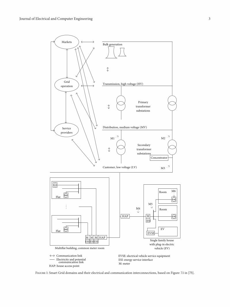
Many national and international organizations are currentlydrawing up roadmaps for SG standards [8–12]. For brevity,the following orients itself on the work by the US NationalInstitute of Standards and Technology (NIST). To structurethe various areas of the Smart Grid, NIST devised a domain-based conceptual model [13]. Each domain contains actorsthat with the help of communications might act over domainborders. The definitions of domains and actors are repro-duced in Table 1. The interconnections between domainsare displayed in Figure 1. It has been common practice todistinguish power line communication scenarios accordingto operation voltages of the power lines [14]. Figure 1 links thisvoltage-based differentiation to the NIST conceptual model.
High-voltage (HV) lines, with voltages in the rangefrom 110 kV to 380 kV, are used for nationwide or eveninternational power transfer and consist of long overheadlines with little or no branches. This makes them acceptablewave guides with less attenuation per line length as fortheir medium- and low-voltage counterparts. However, theirpotential for broadband SG communication services has upto the present day been limited. Time-varying high-voltagearcing and corona noise with noise power fluctuations in theorder of several tens of dBs and the practicalities and costsof coupling communication signals in and out of theses lineshave been an issue. Further, there is a fierce competition offiber optical links. In some cases, these links might even bespliced together with the ground conductor of the HV system[15, 16]. Nevertheless, several successful trials using HV lineshave been reported in [17–20].
Medium-Voltage (MV) lines, with voltages in the rangefrom 10 kV to 30 kV, are connected to the HV lines viaprimary transformer substations. The MV lines are usedfor power distribution between cities, towns, and largerindustrial customers. They can be realized as overhead orunderground lines. Further, they exhibit a low level ofbranches and directly connect to intelligent electronic devices(IEDs) such as reclosers, sectionalizers, capacitor banks, andphasor measurement units. IED monitoring and controlrequires only relatively low data rates, and NB-PLC canprovide economically competitive communication solutionsfor these tasks. MV-related studies and trials can be found in[21–23].
Low-voltage (LV) lines, with voltages in the range from110V to 400V, are connected to the MV lines via secondarytransformer substations. A communication signal on an MVline can pass through the secondary transformer onto theLV line, however, with a heavy attenuation in the order of55 dB to 75 dB [24]. Hence, a special coupling device (induc-tive, capacitive) or a PLC repeater is frequently requiredif one wants to establish a high data rate communicationspath. As indicated in Figure 1, the LV lines lead directly orover street cabinets to the end customers’ premises. Notethat a considerable regional topology difference exits. Forexample in the USA a smaller secondary transformer on autility pole might service a single house or a small numberof houses. In Europe, however, it is more common thatup to 100 households get served from a single secondarytransformer substation. Further, as pointed out in [25],significant differences exist between building types. Theymay be categorized as multiflat buildings with riser, multiflatbuildings with common meter room, single family houses, andhigh-rise buildings.Their different electrical wiring topologiesinfluence signal attenuation as well as interference betweenneighboring PLC networks [26].
In most cases the electrical grid enters the customers’premises over a house access point (HAP) followed by anelectricity meter (M) and a distribution board (fuse box). Onefrequently refers to PLC systems operating up to this pointasAccess systems. Delivering broadband Internet Access overthe electrical grid, also known as broadband over powerline (BPL), amounted at the end of 2008 to less then 1%of the worlds Access customers (65% used DSL, 21% usedcable) [27]. BPL is, however, on the rise, especially in ruralareas and in developing countries with a poorly developedfixed telephone line and coaxial cable infrastructure [16].Apart from general Internet Access, automated meter reading(AMR) systems frequently used ultranarrowband power linecommunication (UNB-PLC) technologies like Turtle [28]and TWACS [29, 30] to gain access and control over theenergy meters within private homes. UNB-PLC systemsare usually designed to communicate over long distanceswith their signals passing through the LV/MV transformers.This helps to keep the amount of required modems andrepeaters to a minimum. Drawbacks are low data rates inthe order of 0.001 bit/s and 60 bit/s for Turtle and TWACS,respectively, and sometimes limitations to unidirectionalcommunications. These UNB-PLC technologies are men-tioned here as they are among the pioneers in the AMR
Journal of Electrical and Computer Engineering 3
...
Secondary
substations
Flat
ESIHAP
Flat
HAP M
Room M6
M1 M2
M3
M4M5
Room
MM MESIESI
ESI
Primary
substations
EVSE
operation
Service
Markets
EV
Bulk generation
Transmission, high voltage (HV)Grid
Distribution, medium voltage (MV)
transformer
transformer
Customer, low voltage (LV)
providers
Multiflat building, common meter room
Single family housewith plug-in electric
vehicle (EV)
Electricity and potentialcommunication link
Communication link
HAP: house access point
EVSE: electrical vehicle service equipmentESI: energy service interfaceM: meter
Concentrator
Figure 1: Smart Grid domains and their electrical and communication interconnections, based on Figure 7.1 in [75].
4 Journal of Electrical and Computer Engineering
and distribution automation field. However, in the light ofmany upcoming Smart Grid deployments, there are muchhigher requirements on the communication infrastructure,for example, to support demand response, distributed genera-tion, and demand side management applications. It is believedthat these applications can, among others, be supported byPLC-basedAdvancedMetering Infrastructure (AMI). Awholewealth of material on AMI requirements and architecturesis available, for example, from the European OPEN meterproject [31]. To cope with increased AMI requirements, thispaper leaves UNB-PLC solutions at a sideline in favour ofmore recent narrowband PLC (NB-PLC) technologies, suchas Power line-Related Intelligent Metering Evolution (PRIME)[32], and G3-PLC [33, 34]. NB-PLC bidirectional data rateslie in the order of hundred kbit/s, while partly preservingthe advantage to communicate over long ranges and throughtransformers.
From the distribution board the LV lines run up to thedifferent power sockets in every room. Lines may also runto an electric vehicle service equipment (EVSE) as indicated inFigure 1. For reliable home area network (HAN) high data rateapplications, broadband power line communication (BB-PLC)technologies are becoming more and more attractive. Field-proven BB-PLC technologies provide data rates of more than200Mbit/s [35],making it easy to fulfill the users’ home enter-tainment needs including high definition television (HDTV).Upcoming SG services in the home include granular controlof smart appliances, the ability to remotely manage electricaldevices, and the display of consumption data. Consumerawareness usually leads to a change in consumption habitsand in the sequel to energy savings between 10% and 20%[36].
NB-PLC solutions have for a long time been used forhome automation applications [14], and it is believed that thewell-established automation systems, like BACnet [37], KNX(ISO/IEC 14543-3-5, EN 50090) [38], and LON (ISO/IEC14908-3, ANSI 709.2) [39, 40], are being integrated intoupcoming Smart Home concepts [10]. Nevertheless the fol-lowing also leaves these technologies at a sideline in favor ofmore recent standards like IEEE 1901 and ITU-TG.hn for BB-PLC applications and IEEE 1901.2 and ITU-TG.hnem forNB-PLC applications.
3. Channel and Noise Aspects
The power line channel and noise situations heavily dependon the scenario and, hence, span a very large range. Generally,it can be said that the PLC channel exhibits frequencyselective multipath fading and a low-pass behaviour. Further,alternating-current- (AC) related cyclic short-term variationsand abrupt long-term variations can be observed.
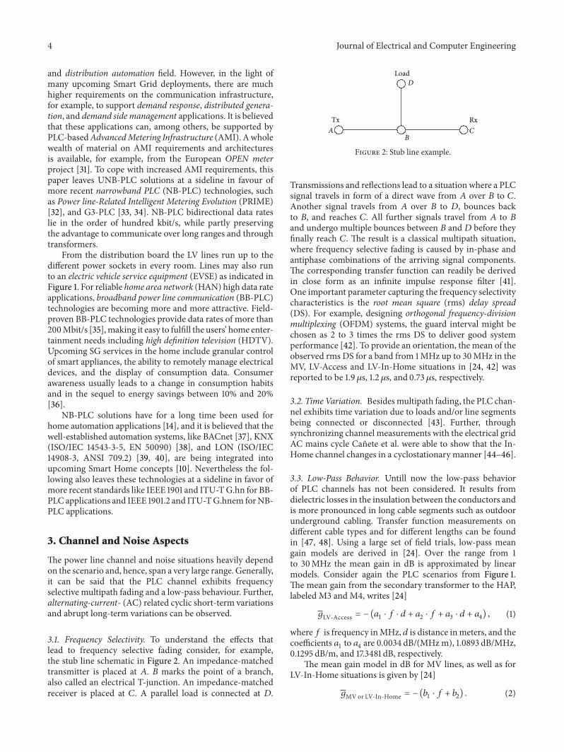
3.1. Frequency Selectivity. To understand the effects thatlead to frequency selective fading consider, for example,the stub line schematic in Figure 2. An impedance-matchedtransmitter is placed at 𝐴. 𝐵 marks the point of a branch,also called an electrical T-junction. An impedance-matchedreceiver is placed at 𝐶. A parallel load is connected at 𝐷.
Tx Rx
Load
Figure 2: Stub line example.
Transmissions and reflections lead to a situation where a PLCsignal travels in form of a direct wave from 𝐴 over 𝐵 to 𝐶.Another signal travels from 𝐴 over 𝐵 to 𝐷, bounces backto 𝐵, and reaches 𝐶. All further signals travel from 𝐴 to 𝐵and undergo multiple bounces between 𝐵 and 𝐷 before theyfinally reach 𝐶. The result is a classical multipath situation,where frequency selective fading is caused by in-phase andantiphase combinations of the arriving signal components.The corresponding transfer function can readily be derivedin close form as an infinite impulse response filter [41].One important parameter capturing the frequency selectivitycharacteristics is the root mean square (rms) delay spread(DS). For example, designing orthogonal frequency-divisionmultiplexing (OFDM) systems, the guard interval might bechosen as 2 to 3 times the rms DS to deliver good systemperformance [42]. To provide an orientation, the mean of theobserved rms DS for a band from 1MHz up to 30MHz in theMV, LV-Access and LV-In-Home situations in [24, 42] wasreported to be 1.9 𝜇s, 1.2 𝜇s, and 0.73 𝜇s, respectively.
3.2. Time Variation. Besidesmultipath fading, the PLC chan-nel exhibits time variation due to loads and/or line segmentsbeing connected or disconnected [43]. Further, throughsynchronizing channel measurements with the electrical gridAC mains cycle Canete et al. were able to show that the In-Home channel changes in a cyclostationary manner [44–46].
3.3. Low-Pass Behavior. Untill now the low-pass behaviorof PLC channels has not been considered. It results fromdielectric losses in the insulation between the conductors andis more pronounced in long cable segments such as outdoorunderground cabling. Transfer function measurements ondifferent cable types and for different lengths can be foundin [47, 48]. Using a large set of field trials, low-pass meangain models are derived in [24]. Over the range from 1to 30MHz the mean gain in dB is approximated by linearmodels. Consider again the PLC scenarios from Figure 1.The mean gain from the secondary transformer to the HAP,labeled M3 and M4, writes [24]
𝑔LV-Access = − (𝑎1 ⋅ 𝑓 ⋅ 𝑑 + 𝑎2 ⋅ 𝑓 + 𝑎3 ⋅ 𝑑 + 𝑎4) , (1)
where𝑓 is frequency inMHz, 𝑑 is distance inmeters, and thecoefficients 𝑎
1to 𝑎4are 0.0034 dB/(MHz m), 1.0893 dB/MHz,
0.1295 dB/m, and 17.3481 dB, respectively.The mean gain model in dB for MV lines, as well as for
LV-In-Home situations is given by [24]
𝑔MVor LV-In-Home = − (𝑏1 ⋅ 𝑓 + 𝑏2) . (2)

Journal of Electrical and Computer Engineering 5
For the LV-In-Home situation the mean gain is givenfrom the mains distribution board to a socket in a room,labelled M5 and M6 in Figure 1. The coefficients are 𝑏
1=
0.596 dB/MHz and 𝑏2= 45.325 dB. The MV gain describes
the channel between two primary transformers on the MVside, indicated by M1 and M2 in Figure 1. Its coefficients are𝑏1= 1.77 dB/MHz and 𝑏
2= 37.9 dB. In both situations the
model is not distant dependent. For the MV situation thisis due to the fact that not enough measurement results wereavailable to construct a distant-dependent model. Hence, inthis case the model is limited to situations where the distancebetweenM1 andM2 is around 510m.Nevertheless, correctionfactors are proposed in [24] to determine the mean gain atother distances. For the LV-In-Home situation the model isnot distance dependent either as “distance” in an In-Homesituation is a hard-to-define term. Power line networks insuch situation exhibit usually a large amount of branches, anda detailed floor plan to determine cable length cannot alwaysbe obtained. This leads to a situation where the low-passbehavior is less pronounced in the In-Home case. Further,in the MV- and the LV-Access situation the attenuationdrastically increases with frequency. This goes well in linewith the findings in [49] and is one of the reasons why BB-PLC Access networks are frequently operated in the lowerfrequency range, for example, between 1 and 10MHz, whileBB-PLC In-Home networks might operate at frequenciesabove 10MHz.
3.4. MIMO Channel. For a long time, the power line chan-nel has been regarded as single-input single-output (SISO)channel, based on two conductors. Nevertheless, in many In-Home installations three wires, namely, live (L) (also calledphase (P)),neutral (N), and protective earth (PE), are common[50]. Further, medium- and high-voltage installations oftenmake use of four or more conductors. In this respect, atheoretical framework of multiconductor transmission linetheory is extensively treated in [51]. Further, channel char-acterization and modeling work directly related to multicon-ductor PLC are available in [52–63].
3.5. MIMO Couplers. In general, the observed channel char-acteristics are not independent from the coupling devicesused to inject and receive the power line signal. Figure 3presents feeding and receiving possibilities for MIMO powerline communication, that is, (a) a Delta-style coupler, (b) a T-style coupler [55], and (c) a Star-style coupler [64]. Couplerdesigns are tightly related to radiated emission treated inmore detail in Section 4 [62]. According to the Biot-Savartlaw themain source of radiated emission is the commonmode(CM) current [65]. To avoid radiated emission, traditionallyPLC modem manufacturers aim at injecting the signal assymmetrically as possible. In this way, two 180∘ out ofphase electric fields are generated that neutralize each otherresulting in little radiated emission.This desired symmetricalway of propagation is also known as differential mode (DM).Specifically, to avoid the injection of CM, feedingMIMOPLCsignals can be done using the delta or T-style couplers fromFigures 3(a) or 3(b). The delta, also called transversal probe,
D1
D2
D3
L
N
PE
Delta-style
T1
T2
L
N
PE
T-style
L
NPE
S1S2S3S4
Star-style
(a) (b)
(c)
Figure 3: MIMO PLC couplers.
consists of three baluns arranged in a triangle between L, N,and PE. The T-style coupler feeds a differential mode signalbetween L and N plus a second signal between the middlepoint of L-N to PE. Receiving the PLC signals is also possibleusing the star-style or longitudinal coupler. There three wiresare connected in a star topology to the center point. Thebenefit of this coupler is the possibility to receive CM signalswhich enables a forth reception path. On average CM signalsare less attenuated than DM signals [64]. This is why it maybe interesting to receive them, especially for highly attenuatedchannels.
3.6. Noise Characterization and Modeling. Turning from thechannel to the noise situation, power line noises can begrouped based on temporal and spectral characteristics.Following, for example, [48, 66] one can distinguish coloredbackground noise, narrowband noise, periodic impulsive noiseasynchronous to the AC frequency, periodic impulsive noisesynchronous to the AC frequency, and aperiodic impulsivenoise. In [48] all these noises are modeled directly at thereceiver using a superposition of spectrally filtered additivewhite Gaussian noise (AWGN), modulated sinusoidal signals,andMarkov processes. Instead of modeling the noise directlyat the receiver, Canete et al. proposed tomodel the noise at itsorigin and to filter it by the channel transfer function [44, 67].Besides, specific results onMIMO system noise are presentedin [68, 69].
A statistical approach to average colored backgroundnoise modeling is presented in [24] based on a large amountof noise measurements in MV, LV-Access and LV-In-Homesituations. Although a lot of the details get lost by averaging,the results can still deliver some interesting rule of thumbwhen one wants to determine a likely average noise level.One general finding is that the mean noise power falls offexponentially with frequency. Derived from [24] the meannoise power spectral density (PSD) in dBm/Hz is given by
𝑃𝑁= 𝑐1⋅ 𝑒(−𝑐2⋅𝑓)+ 𝑐3− 10 ⋅ log
10(30000) , (3)

6 Journal of Electrical and Computer Engineering
Table 2: Mean noise model coefficients [70] © 2010 John Wiley &Sons.
Location 𝑐1, 𝑐
2, 𝑐
3,
[dB] [1/MHz] [dBm/Hz]M1 and 2, SecondaryTransformer, MV 37 0,17 −105
M3, Secondary Transformer, LV 24,613 0,105 −116,72M4, House access point, LV 29,282 0,12 −114,94M5, Main distribution board, LV 39,794 0,07 −118,08M6, Socket in private home, LV 17,327 0,074 −115,172
where the last term normalizes out the 30 kHz bandwidthused in the noise measurement process. The coefficients𝑐1to 𝑐3are given in Table 2. The resulting noise models
correspond to the measurement points M1 to M6 in Figure 1.
3.7. Mean SNR Considerations. Details on Tx limits will bediscussed in Section 4. For simplicity, assume for now that apower line signal with 𝑃
𝑆= −50 dBm/Hz may be injected.
Using the gain and noise models from (1) to (3) the meansignal-to-noise ratio (SNR) can then be calculated as
SNR = 𝑔 + 𝑃𝑆− 𝑃𝑁. (4)
The mean SNRs for the various connections between themeasurement points M1 to M6 in Figure 1 are plotted inFigure 4. One should note that, although the channel gainbetween two measurement points is symmetric, the noise atthe measurement points differs. Hence, five different curvesare produced.
It can be seen that especially the lower part of thespectrum, up to 10MHz, is very well suited for Access andBackhaul applications. Further, for In-Home applications theentire spectrum from 1 to 30MHz promises high mean SNRsin the order of 40 dB, which goes also well in line with thefindings in [71]. Further interesting results for the frequencyrange up to 100MHz are available in [61–63, 69, 72].
In general, the results show that there is a high potentialfor PLC if the estimated mean SNRs can be exploited inPLC modems. However, the presented mean results have tobe handled with care. One should bear in mind that themean SNR models from [24] exhibit a significant standarddeviation. Further, effects due to frequency selectivity, nar-rowband interference, impulsive noise, and time variation arenot reflected in Figure 4. Whether the estimated mean SNRstranslate into high PLC data rates depends not at last on thePLC modem’s signal processing algorithms, its componentquality, and permissible implementation complexity.
4. Electromagnetic Compatibility Regulations
Power line cables were not designed to carry communicationsignals and, hence, give rise to conducted emission, as wellas radiated emission that may interfere, for example, withAmateur Radio or radio broadcast receivers.When looking atpower line electromagnetic compatibility (EMC) regulations,
5
15
25
35
45
55
0 5 10 15 20 25 30− 15
− 5
Frequency (MHz)
Mea
n SN
R (d
B)
M1 to M2, subst. to MV subst.M3 to M4, LV subst. to HAPM4 to M3, HPA to LV subst.M5 to M6, mains dist. to socketM6 to M5, socket to main dist.
Figure 4: Mean SNR based on –50 dBm/Hz injected PSD, as well asmean channel gain and mean noise power spectral density models.
one may distinguish between regulations for NB-PLC andBB-PLC.
The NB-PLC regulations deal with the spectrum from3 kHz up to around 500 kHz. Important NB-PLC regulationsare listed in Table 3. Being a subset of all other bands,the European Committee for Electrotechnical Standardization(CENELEC) bands are the only ones available on a globalbasis. Four CENELEC bands are defined as 𝐴 (3–95 kHz), 𝐵(95–125 kHz), 𝐶 (125–140 kHz), and 𝐷 (140–148.5 kHz) [73].Besides specifying transmission limits and their measure-ment procedures, the CENELEC standard alsomandates thatthe A band may only be used by Energy Suppliers and theirlicensees, while the other bands may be used by consumers.Further, devices operating in C band have to comply with acarrier sense medium access/collision avoidance (CSMA/CA)protocol that allows a maximum channel holding period of1 s, a minimum durations between channel uses by the samedevice of 125ms, and aminimum time of 85ms before declar-ing the channel idle. For theUSA, there are currently ongoingefforts [74] to specify the band from 9 kHz to 534 kHz forNB-PLC operations with a mandatory CSMA/CA protocolcompliant with CENELEC EN 50065-1 [73]. The advantagesare that equipment manufacturers would be easily able toadapt their NB-PLC products to the EU andUSAmarket andto many other markets that follow these standards.
Turning the view to BB-PLC one may again distinguishtwo frequency ranges, that is, 1MHz to 30MHz, whereconducted emission is at the focus of regulation, and 30MHzto 100MHz, where the focus shifts to radiated emission.
The Comite International Special des PerturbationsRadioelectriques (CISPR), founded in 1934 and now part ofthe International Electrotechnical Commission (IEC), was

Journal of Electrical and Computer Engineering 7
Table 3: Important regulations related to NB-PLC [75] © 2012 JohnWiley & Sons.
States Frequ.[kHz] Institution References
EU 3–148.5Comite Europeen de
NormalisationElectrotechnique (CENELEC)
[73]
US 10–490 Federal CommunicationsCommission (FCC) [76]
Japan 10–450 Association of Radio Industriesand Businesses (ARIB) [77]
making efforts to regulate BB-PLC generated interference.At the beginning CISPR 22 [78] defined two sets of limitsand measurement methods for conducted emissions oftelecommunication equipment. One set was defined for thetelecommunication port, and the other was defined for themains port. For PLC modems, it is not defined whether thePLC signal port, which at the same time is used for powersupply, is considered as a mains or as telecommunicationport. The method for telecommunication ports respects thesymmetry properties of the attached cable. Asymmetries likean open light switch or asymmetrical parasitic capacitancesconvert the symmetrically fed signals into commonmode signals [65]. However, the method used for devicesconnected to the mains, specified in CISPR 16 [79], is basedon measuring the asymmetric voltage level of either thephase or neutral wire to the ground. From the perspectiveof a PLC modem, this is the worst case, because this voltageconsists of asymmetric and symmetric voltage; that is, notonly the emission, and therewith the interference relevantpart, but also the desired signal is measured and comparedagainst emission limits. IEC CISPR/I/89/CD [80] tried toclarify the situation by interpreting PLC as an applicationfollowing the telecommunication limits of CIPSR 22.Therefore, the longitudinal conversion loss (LCL) parameterwas used in an identical way as, for example, in the testingof digital subscriber line (DSL) equipment. The benefit ofusing the LCL parameter is the simplicity of measuring it.It is a reflection parameter whose measurement requiresan equipment to be connected to only one location of thegrid. Other possibilities to verify the potential of interferencewould have been to place antennas and measure the fieldgenerated by the fed PLC signal. However, this would makea measurement setup significantly more cumbersome anderror prone. Nevertheless, with respect to highly attenuatedwires like the power lines the much simpler measurementof a reflection parameter as in [80] only describes thelocal situation instead of giving detailed insight of what ishappening if a PLC signal travels deeply into the electricalnetwork. In 2008, CISPR/I/257/CD [81] was publishedwith an LCL parameter reduced by 6 dB. Simultaneously,CISPR/I/258/CD [82] indicated that mitigation techniqueslike cognitive notching for PLC modems [64, 83] anddynamic transmit power management are the compromiseto solve the never-ending EMC discussions. CIS/I/301/CD[84] answered the question of whether PLC is connected
to the telecommunication port or to the mains port byintroducing a Power Line Telecommunication (PLT) port.In this document the electro magnetic interference (EMI)mitigation techniques are specified as normative. However,CISPR never proposed a committee draft for voting (CDV).This is why CENELEC became active after the lifetime of theCISPR committee to find at least in Europe an acceptablesolution. The result, prEN 50561-1:2012 [85] additionallyexcludes the aeronautical frequencies from power linecommunication and specifies the following.
(i) An emission measurement procedure at the PLT portwhile no communication takes place.
(ii) A second emission measurement procedure at thePLT port when normal PLC takes place.
(iii) A general cap on the injected PSD of −55 dBm/Hz.(iv) Permanent notching of certain parts of the radio spec-
trum, that is related to amateur radio and aeronauticalbands.
(v) A procedure for adaptive notching, meaning that thePLC equipment senses the presence of radio servicesand notches the affected frequencies for its ownoperation.
(vi) A procedure of adaptive transmit power manage-ment,meaning that the transmitting equipment limitsits transmit power as a function of channel attenua-tion and noise to a level below the allowedmaximum,that is just sufficient to achieve the required data rate.
EN50561-1:2012 was approved in November 2012, whichfinally gives certainty to PLC stakeholders on interferencelimits.
In the USA the Federal Communications Commission(FCC) is in charge of regulating electromagnetic emissions.In general, all digital equipments have to comply with theFCC part 15 standard (47 CFR §15) [76]. Specifically, AccessPLC systems over medium- and low-voltage power linesand for a frequency range from 1.705 to 80MHz are treatedin the standard’s Section G. Conducted emission limits areexplicitly not applicable, but radiated emission limits areimposed through a transmit power spectral density mask.Additionally, PLC systems have to be able to notch certainfrequencies that might be used by other services. Further,the FCC defines excluded bands where no PLC signal shallbe injected, as well as geographical exclusion zones close towhich no Access PLC systemsmay be deployed. Further, pro-cedures in which service providers inform about prospectivePLCAccess deployments and complaint handling proceduresare a requirement.
More details on PLC EMC regulations as well as con-ducted and radiated interference measurement results can befound in [6, 61, 86]. Besides, the “IEEE Standard for PowerLine Communication Equipment—Electromagnetic Compati-bility (EMC) Requirements—Testing and Measurement Meth-ods” [87] was recently released, intending to provide aninternationally recognized EMC measurement and testingmethodology. It endorses among others CISPER22 and FCCpart 15 as normative references, but does not establish

8 Journal of Electrical and Computer Engineering
any emission limits itself. Looking at the developments inCISPR/CENELEC and at FCC part 15, it becomes clear thatnext generation PLC equipment has to be highly configurableto apply power spectral density-shaping masks, as well asadaptive notching.
5. Narrowband PLC
Narrowband power line communication systems usuallyoperate in the frequency range from 3 kHz to 500 kHz, that is,theCENELEC/ARIB/FCCbands. Following, for example, thenomenclature in [5], they can be subdivided into low data rate(LDR) and high data rate (HDR) systems. LDR systems havethroughputs of a few kbit/s and usually are based on singlecarrier technology. Example standards, listed in the NISTSmart Grid Interoperability Panel (SGIP)Catalog of Standards[3, 13], are ISO/IEC 14908-3 (LON, ANSI/EIA 709.2) [39,40] and ISO/IEC 14543-3-5 (KNX, EN 50090) [38]. Thesestandards span all layers of the open systems interconnection(OSI) model and can, besides over power line, also be usedover other media such as twisted pair and in some cases evenwirelessly. Their main area of application has been industrialand building automation. In this respect a further popularprotocol is BACnet (ISO 16484-5 [37]). The following, how-ever, will focus on the physical layer (PHY) of high data rate(up to 1Mbit/s) NB-PLC. As in many other communicationsystems OFDM has emerged as the modulation scheme ofchoice for HDR NB-PLC. Example HDR NB-PLC systemsare G3-PLC [33] and PRIME [88] that have made it into ITUG.hnem standardization as ITUG.9903 [89] and ITUG.9904[90], respectively. Both are also supported via interoperabilitymodes in IEEE 1901.2. With respect to coexistence, theNIST priority action plan 15 (PAP15) working group recentlyapproved that newly developed NB-PLC standards shall allimplement a single coexistence protocol as to “have minimalperformance impact on the existing deployed devices,” that is,devices using ISO/IEC 14543-3-5, IEC 61334-3-1, IEC 61334-5-1, IEC 61334-5-2, and IEC 61334-4-32 [91].
5.1. PRIME. PRIME, for Power line-Related Intelligent-Metering Evolution, was developed within the PRIME Alli-ance, with its steering committee chaired by the Spanishutility heavyweight Iberdrola [32]. The PRIME system usesa total of 96 ODFM subcarriers over the frequencies from42 kHz to 89 kHz, that is, within the CENELEC A-band.Further, it deploys differential binary, quaternary, and eight-phase shift keying (BPSK, QPSK, and 8PSK) and an optional1/2-rate convolutional code. Therewith it is able to achieve aPHY peak data rate of 128.6 kbit/s [92]. The OFDM symbolinterval is of 2240𝜇s including a 192 𝜇s cyclic prefix whichsuffices to deal with most common power line delay spreads.Further, to deal with unpredictable impulsive noise PRIMEoffers the option to implement automatic retransmissionrequest (ARQ), based on the selective repeat mechanism.Turning to the system architecture, PRIME is forming sub-networks, where each subnetwork has one Base Node andseveral Service Nodes. The base node is the “master” thatmanages the subnetwork’s resources and connections usinga periodically sent beacon signal. The base node is further
responsible for PLC channel access arbitration. A contentionfree and a contention-based access mechanism exists, whoseusage time and duration are decided by the base node.Withinthe contention-free time division multiplex (TDM) channelaccess period, the base node assigns the channel to only onenode at a time. The contention-based access uses CSMA/CA[88, 92]. To assure privacy, authentication, and data integrity aSecurity Profile 1 is defined, that uses 128-bit AES encryption[93].The specification also defines a Security Profile 0 equiva-lent to no encryption and leaves room for the definition of twofurther security profiles in future releases. To interface MACand application layer, PRIME defines a convergence layer(CL) between the two. The CL can be split into a CommonPart Convergence Sublayer (CPCS) and a Service SpecificConvergence Sublayer (SSCS). The CPCS performs tasks ofdata segmentation and reassembling and is adjusted to thespecific application. Three SSCSs are currently defined: the“NULL Convergence Sublayer provides the MAC layer with atransparent way to the application, being as simple as possibleand minimizing the overhead. It is intended for applicationsthat do not need any special convergence capability.” “TheIPv4 Convergence Layer provides an efficient method fortransferring IPv4 packets over the PRIME network.” Finally,the IEC 61334-4-32 Convergence Layer “supports the sameprimitives as the IEC 61334-4-32 standard” [94], making iteasy, for example, to support advanced metering applicationsthat make use of the standardised data models of IEC 62056-62 [95]. PRIME could therefore also be used to replace theaging PHY and MAC layer of the single carrier power linestandard IEC 61334-5-1 [96], also known as S-FSK, for spreadfrequency shift keying.
5.2. G3-PLC. The other OFDM-based HDR NB-PLC speci-fication, G3-PLC [97–99] was published in August 2009. Itcan be configured to operate in the internationally acceptedbands from 10 kHz to 490 kHz (FCC, CENELEC, and ARIB).Using differential BPSK, QPSK, and 8PSK for constellationmapping and concatenated convolutional Reed-Solomon for-ward error correction coding, it reaches PHY peak data ratesclose to 300 kbit/s. Peak and typical data rates for variousfrequency bands have been reported in [100] and are, forconvenience, also listed in Table 4. The MAC layer is basedon IEEE 802.15.4-2006 [101]. 6LoWPAN [102] is used to adaptthe IEEE 802.15.4-2006 MAC to IPv6 [103]. This allows theapplication layer to comply with ANSI C12.19/C12.22 [104] orIEC 62056-61/62 (DLMS/COSEM) [105, 106] to run standardInternet services.
A comparison between PRIME and G3-PLC, mainlyfocusing on physical layer aspects is presented in [107].There it is found that G3-PLC is slightly more robust whendisturbed by AWGN and narrowband interference, whilePRIME is the less complex system, which could allow cheaperimplementations.
5.3. IEEE 1901.2 and ITU-T G.hnem. The specificationsPRIME and G3-PLC form the baseline in the ongoing NB-PLC standardization processes within IEEE 1901.2 [108].Compliant devices are supposed to support interoperabilitymodes with PRIME and G3-PLC in the CENELEC A band

Journal of Electrical and Computer Engineering 9
Table 4: G3-PLC data rates, based on [100].
Frequency band Peak rate,[kbit/s]
Typical rate,[kbit/s]
CENELEC (36 kHz to 91 kHz) 46 44FCC (150 kHz to 487.5 kHz) 234 187FCC (10 kHz to 487.5 kHz) 298 225
and have as minimum a requirement to implement one ofthe PHY/MACs referred to as Main 1901.2, G3 CENELEC A,andPRIMECENELECA [109]. G3-PLC andPRIMEhave alsobeen approved as ITU recommendations G.9903 [89] andG.9904 [90], respectively in October 2012. Together with ITUG.9901 [110] and ITU G.9902 [111] they now supersede whatwas formally ITU G.9955/G9956. ITU G.hnem developmentis oriented on Smart Grid use cases, like support of pricingawareness, load control, and demand response, and it has beenagreed to meet the requirements set forth by NIST PAP15.
There are still some open issues, for example, with respectto ITU G.hnem IEEE 1901.2 coexistence. Implementers thatcannot wait might consider that due to relatively low signalprocessing complexity, NB-PLC modems can be imple-mented on a digital signal processor (DSP). This allows forupgradeability via software updates and can especially bean advantage for early stage customer premises deploymentswhere a hardware update would be prohibitively expensive.An upgradeable DSP solution that supports PRIME as well asG3-PLC is, for example, offered by Texas Instruments [112].
6. Broadband PLC
In the last decade, BB-PLC chips by semiconductor vendors,such as Intellon (in 2009 acquired by Atheros, Atheros in2011 acquired by Qualcomm) [113], DS2 (in 2010 acquiredby Marvell) [114], Gigle (in 2010 acquired by Broadcom)[115], and Panasonic [116], came to market that operatein the band from around 1MHz to 300MHz. The chipsare mainly based on three consortia backed specificationsdeveloped within the frameworks of the HomePlug Pow-erline Alliance (HomePlug) [117], the Universal PowerlineAssociation (UPA) [118], and the High Definition Power LineCommunication (HD-PLC) Alliance [119]. Related productsallow data rates around 200Mbit/s and are not interoper-able. However, to make PLC systems a broad success, aninternationally adopted BP-PLC standard became essential.The International Telecommunications Union (ITU) as wellas the Institute of Electrical and Electronics Engineers (IEEE)commencedwork on such next generation standards, namely,ITU-T G.hn and IEEE 1901. ITU-TG.hn is not only applicableto power lines, but also to phone lines and coaxial cables,therewith for the first time defining a single standard for allmajor wireline communications media. At the end of 2008,the PHY layer and the overall architecture were consentedin ITU-T Recommendation G.9960 [120]. The Data LinkLayer (DLL) Recommendation G.9961 [121] was approved inJune 2010, and a MIMO transceiver extension G.9963 wasconsented in September 2011 [122]. Alongside, theHomeGrid
Forum was founded to promote the ITU-T G.hn standardand to address certification and interoperability issues [123].Simultaneously, IEEE P1901 [124] was working on the “DraftStandard for Broadband over Power Line Networks: MediumAccess Control and Physical Layer Specifications” [125]. Itcovers the aspects Access, In-Home, and coexistence ofAccess-In-Home and In-Home-In-Home networks, and theofficial IEEE Std 1901–2010 was published on December, 30,2010, with the HomePlug Powerline Alliance [117] being acertifying body for IEEE 1901 compliant products. In analogyto the introduction of MIMO to ITU G.hn, the HomePlugAlliance introduced the HomePlug AV2 specification in Jan-uary 2012.TheHomePlug AV2 specification includes featureslike MIMOwith beamforming, an extended frequency rangeof up to 86MHz, efficient notching, several transmit poweroptimization techniques, 4096-QAM, power save modes,short delimiter, and delayed acknowledgement, boostingthe maximum PHY rate to around 2Gbit/s. Further, tocover multiple home networking media under one umbrella,IEEE P1905.1 is working on a standard for a convergentdigital home network for heterogeneous technologies [126].It defines an abstraction layer for multiple home networkingtechnologies like IEEE 1901, IEEE 802.11 (Wi-Fi), IEEE 802.3(Ethernet), and MoCA 1.1 and is extendable to work withother home networking technologies.
6.1. IEEE 1901 and ITU-T G.hn. IEEE 1901 uses the bandfrom 2MHz up to 50MHz with services above 30MHz beingoptional. ITU-T G.hn (G.9960/G.9961) operates from 2MHzup to 100MHz using bandwidth scalability, with three dis-tinct and interoperable bands defined as 2–25, 2–50, and 2–100MHz. The architectures defined by IEEE 1901 and ITU-TG.hn (G.9960/G.9961) are similar in several aspects. In G.hnone refers to a subnetwork as Domain. Operation, as wellas communication is organized by the Domain Master whocommunicates with variousNodes. Similarly, the subnetworkin 1901 is referred to as Basic Service Set (BSS).The equivalentto the domain master is the BSS Manager, which connectsto so-called Stations. These basic network components withtheir system specific terminology are summarized in Table 5.
While the general concepts are similar, one should notethat G.hn defines a PHY/DLL used for operation overany wireline medium. Primarily, the OFDM parameters areadjusted to account for different medium-dependent channeland noise characteristics. On the contrary, IEEE 1901 definestwo disparate PHY/MAC technologies based on HomePlugAV and HD-PLC. One of the key differences is their fre-quency division-multiplexing scheme. The HomePlug AV-based version uses the Fast Fourier Transform (FFT), whilethe HD-PLC based version uses Wavelets. Hence, they aresometimes also referred to as FFT-PHY and Wavelet-PHY,respectively. A special coexistence mechanism has to be usedwhen operating IEEE 1901 devices from both PHYs on thesame power line which is standardized within IEEE 1901 asInter-System Protocol (ISP) (see also [127] or [128]). A nearlyidentical mechanism was standardized by ITU-T in G.9972[129], also known as G.cx. Technical contributions to ITU,and IEEE from members of the NIST PAP15 assured thealignment of both standards. As a result, it is likely that the

10 Journal of Electrical and Computer Engineering
Table 5: Synopsis of terms used in the BB-PLC standards ITU-TG.hn and IEEE 1901 [75] © 2012 John Wiley & Sons.
Network item ITU-T G.hn IEEE P1901
Sub-network Domain Basic Service Set(BSS)
Transceiver Node Station (STA)Sub-network controller Domain Master BSS Manager
Access control schedule Media Access Plan(MAP) Beacon
Timeframe MAC cycle Beacon Interval
Access methods
CSMA/CA, TDMA,STXOP
(shared transmissionopportunities)
CSMA/CA,TDMA
Relaying Relay (L2) Repeater (L2)Network controller Relay (assigned Proxy BSSproxy as a proxy) ManagerTransceiver Hidden Hidden(not directly reached) Node Station
NIST SGIP will mandate that all BB-PLC technologies imple-ment Recommendation ITU-T G.9972 or ISP [130]. ISP/G.cxprovides coexistence by splitting time equally among systemspresent on the line. IEEE 1901 additionally specifies theoptional Coexistence Protocol (CXP), that provides coexis-tence among multiple technologies based on a first-come-first-serve basis.
The coexistence mechanism is thought for the case wheredisparate networks would otherwise be interfering witheach other. Another likely scenario is that same technologynetworks exist in close proximity, with the risk of so-calledneighboring network interference. To deal with neighboringnetwork interference G.hn uses different preamble-symbolseeds in each network. Therewith, G.hn networks are able tocoexist and communicate simultaneously, that is, not usingtime division. Instead, link adaptation procedures adjust thethroughput to cope with degraded signal to interference plusnoise ratios (SINR). In many cases the throughput will bethrottled only slightly allowing G.hn networks to coexistnearly unimpeded. On the other hand, IEEE 1901 relies ona CSMA/CA medium access strategy, which may lead to anincreased number of collisions. As countermeasure, IEEE1901 introduces a coordinated mode that allows neighboringnetworks to allocate times over the shared medium forspecific communications. This coordinated time divisionmultiple access (TDMA) mode enables traffic to get throughunimpeded albeit at the price of time division (orthogonalthroughput sharing).
6.2. ITU-T G.hn Low Complexity Profile. It is envisionedthat G.hn nodes are in the future embedded into SmartGrid home (SGH) area network devices. SGH nodes willtypically make use of the G.hn low complexity profile (LCP),
operating in the frequency range 2–25MHz. This allows forreduced component cost and power consumption. ExampleSGH nodes could be heating and air conditioning appliances,Plug-in Electric Vehicles (PEV), and Electric Vehicle ServiceEquipments (EVSEs) as indicated in Figures 1 and 5. Togetherthey form a multi-domain HAN.
The SGHs interact with the utility’s access network (UAN)and its advanced metering infrastructure (AMI) through anenergy service interface (ESI). The AMI domain comprisesAMIMeters (AM),AMI Submeters (ASM), and an AMIHeadEnd (HE).The HE is a local hub (concentrator), that controlsall meters downstream from it and interfaces to the utility’swide area/backhaul network upstream from it. Each AMIHE supports up to 250 AM and/or ASM nodes formingan AMI domain (in dense urban areas 150 to 200 metersare a frequently encountered maximum). Further, a networksupports up to 16 AMI domains, delivering support for upto 16 ⋅ 250 = 4000 AMI devices. The ability to support16 domains with 250 nodes each is a general property ofG.hn not limited to Smart Grid/AMI applications. Domainsmay be formed over any kind of wiring. The nodes withina domain are grouped into SGH and non-SG nodes. Forsecurity reasons, non-SG nodes are logically separated fromSGH nodes using a secure upper-layer protocol.
In every domain there is a domain master that coor-dinates operation of all nodes. G.hn nodes of differentdomains communicate with each other via InterdomainBridges (IDBs). IDBs are simple data communications bridgeson OSI Layer 3 and above, enabling a node in one domain topass data to a node in another domain. In a multi-domainsituation, a Global Master (GM) provides coordination ofresources, priorities, and operational characteristics betweenG.hn domains. Besides, G.hn domains can be bridged toalien (non-G.hn) domains, for example, to IEEE 1901/1901.2,wireless technologies, and so forth. For example, besides theUAN/AMI connection through the ESI, the HAN might beconnected to the outside world via a DSL or cable modemgateway communicating with the G.hn HAN via an aliendomain bridge.
6.3. HomePlug Green PHY. In analogy to the ITU G.hn lowcomplexity profile (LCP), the HomePlug Powerline Alliancehas released the HomePlug Green PHY specification. Home-Plug GreenPhy is a subset of HomePlug AV that is intendedfor use within Smart Grid applications. It is compatible toHomePlug AV, AV2, and IEEE 1901 and is optimized forlow power applications and costs. GreenPhy uses the mostrobust communication mode (called ROBO) of HomePlugAV technology. OFDM carrier spacing, signal preamble,frame control, and FEC are identical to HomePlug AV toensure interoperability. This also results in identical coverageand reliability to Smart Grid functions. CSMA/CA is usedas channel access scheme. Data rates are up to 10Mbit/s.GreenPhy nodes may use long power save periods if a higherlatency is acceptable. In the sleep state modems have only a3%power consumption compared to the awake time resultingin an average power reduction of more than 90%with respectto standard HomePlug AV products.

Journal of Electrical and Computer Engineering 11
Domain A
Bridge to aliendomain
Domain B
Bridge betweendomains A and B
Non-SG G.
Non-SG
G.9960
G.9960
9960 node
G.9960
node
node
SGHG.9960
node
SGHG.9960
node
SGHG.9960
node
SGHG.9960
node
Non-SGG.9960node
Non-SGG.9960node
Non-SGG.9960node
Non-SGG.9960nodeDMA
Non-SGG.9960nodeDMA
PC
EVSE
Bridge
EMSEV
node (ex.)
G.9960EV
node (ex.)
multimedia
EVCF
AMI domain
Multidomain HAN
AM
G.9960
nodeAM
G.9960
nodeAM
Meter
Residenceboundary
Utility access network(AMI and Smart Grid)
Figure 5: Smart Grid HAN implementation based on G.9960, based on Figure 22 in [138].
7. Application Layer Interoperability
Although there is still an ongoing struggle between stake-holders promoting the various NB-PLC and BB-PLC tech-nologies, it seems clear that IP support will becomeparamount to assure Smart Grid interoperability. Along theselines, the HomePlug Alliance (promoting IEEE P1901) andthe HomeGrid Forum (promoting ITU G.hn/G.hnem) havejoint forces with wireless stakeholders, namely, the Wi-FiAlliance and the ZigBee Alliance. Together they formed theConsortium for Smart Energy Profile 2 (SEP2) Interoperabilitywith the intention “to develop common testing documentsand processes for certifying SEP 2 interoperability” [131].
Smart Energy Profile 2 (SEP2) originates from smartenergy-related upper-layer developments (OSI layer 5 to 7)within the ZigBee Alliance [132]. It is compatible to theInternational Electrotechnical Commission’s Common Infor-mationModel (CIM) [133, 134] and is kept link layer agnostic.Further, it is described using extensible markup language(XML) [135] and follows a Representational State Transfer(REST) [136] architecture. Moreover, data transport takesplace using Hypertext Transfer Protocol (HTTP) [137].
By opting for these widely adopted building blocks, SEP 2can benefit from a large knowledge and developer base andis regarded by NIST as an import specification to allowinteroperability between various home area network devices[13].
8. Conclusions
Although there are strong wireless and wireline communi-cation competitors, it is believed that power line communi-cations (PLCs) will fulfill various communication tasks inupcoming SmartGrid deployments as PLCprovides the natu-ral upgrade from simple electricity conductors to hybrid andbidirectional electricity and data communication solutions.
Seen from a utility point of view, one of the main advan-tages of PLC is the full control over the physical medium,without the need to depend on third party providers liketelecommunication companies or cellular operators. Espe-cially, PLC standardization and harmonization as, for exam-ple, fostered byNISTPAP15, are important for the PLC indus-try as a whole when defending territory against competingwireless and wireline options.
In terms of broadband PLC (BB-PLC), the coexistingstandards ITU-T G.hn and IEEE P1901 with the expandedHomePlug AV2 specification are currently the most promis-ing, while narrowband PLC (NB-PLC) standardization, thatis, IEEE P1901.2 and ITU-T G.hnem, is still ongoing.
Cases where NB-PLC and BB-PLC systems operate onthe same physical medium will become more frequent withincreasing PLC system penetration. Nevertheless, coexis-tence of the two should be straight forward as they areusing different frequency ranges. In general, interconnectionsbetween different coexisting NB-PLC and BB-PLC standards

12 Journal of Electrical and Computer Engineering
can then be established by OSI Layer 3 bridges as suggested,for example, in [108, 138].
When looking at higher layer interoperability, the recentfoundation of the Consortium for Smart Energy Profile2 Interoperability, is a promising step forward to allowusers and operators to deploy various wireless and wirelinetechnologies with seamless interoperability at the applicationlayerwhich is regarded as essential forwidespread SmartGridacceptance.
Acknowledgments
Although this article is distributed under the Creative Com-mons Attribution License, it should be noted that it is inparts based on [70, 75]. The material from [70] and [75] isreproduced with explicit permission of John Wiley & Sons,Ltd. and John Wiley & Sons, Inc., respectively. However,related copyrights and the right to grant reprint permissionsof the affected parts remain with John Wiley & Sons. Thiswork is cofinanced by the Spanish Ministry of Scienceand Innovation (MICINN) Program INNCORPORA-TorresQuevedo 2011, and Grant SICCNALS, TEC2011-28219. Fur-ther it is cofunded by the European Social Fund and theEuropean Regional Development Fund within the ERDFOperational Programme of the Valencian Community 2007–2013, grant no. IMIDTA/2011/905. Special thanks also to theBreezeSolve Team for editorial support.
References
[1] B. A. Hamilton, J. Miller, and B. Renz, “Understanding thebenefits of smart grid,” Tech. Rep. DOE/NETL-2010/1413, U.S.Department of Energy, 2010.
[2] L. T. Berger and K. Iniewski, Smart Grid—Applicacions, Com-munications and Security, John Wiley & Sons, 2012.
[3] M. Burns, “NIST SGIP catalog of standards,” October 2010,http://collaborate.nist.gov/twiki-sggrid/bin/view/SmartGridSGIPCatalogOfStandards.
[4] P. A. Brown, “Power line communications—past present andfuture,” in Proceedings of the International Symposium on PowerLine Communicatons and Its Applications (ISPLC ’99), pp. 1–8,September 1999.
[5] S. Galli, A. Scaglione, and Z. Wang, “For the grid and throughthe grid: the role of power line communications in the smartgrid,” Proceedings of the IEEE, vol. 99, no. 6, pp. 998–1027, 2011.
[6] The OPEN meter Consortium, “Description of currentstate-of-the-art of technology and protocols descriptionof state-of-the-art of PLC-based access technology,”European Union Project Deliverable FP7-ICT-2226369, d 2.1Part 2, Version 2.3, March 2009, http://www.openmeter.com/files/deliverables/OPEN-Meter%20WP2%20D2.1%20part2%20v2.3.pdf.
[7] IEEE Communication Society, “Best readings in power linecommunications,” http://www.comsoc.org/best-readings.
[8] SMB Smart Grid Strategic Group (SG3), “IEC smart grid stan-dardization roadmap,” June 2010, http://www.iec.ch/smartgrid/downloads/sg3 roadmap.pdf.
[9] ITU Telecommunication Standardization Bureau Policy &Technology Watch Division, “Activities in smart grid standard-ization repository,” version 1.0., April 2010, http://www.itu.int/dmspub/itu-t/oth/48/01/T48010000020002PDFE.pdf.
[10] DKE German Commission for Electrical, Electronic &Information Technologies of DIN and VDE, “The Germanroadmap e-energy/smart grid,”April 2010, http://www.e-energy.de/documents/DKE%20Roadmap%20SmartGrid%20230410%20Engllish.pdf.
[11] State Grid Corporation of China, “SGCC framework androadmap for strong and smart grid standards,” August 2010,http://collaborate.nist.gov/twiki-sggrid/pub/SmartGrid/SGIPDocumentsAndReferencesSGAC/China State Grid Framework and Roadmap for SG Standards.pdf.
[12] International Energy Agency, “Technology roadmap smartgrids,” April 2011, http://www.iea.org/publications/freepublications/publication/smartgrids roadmap.pdf.
[13] National Institute of Standards and Technology (NIST) andU.S.Department of Commerce, “NIST framework and roadmap forsmart grid interoperability standards,” NIST Draft Publication,Release 1. 0, January 2010.
[14] K. Dostert, Powerline Communications, Prentice-Hall, 2001.[15] G.Held,Understanding BroadbandOver Power Line, CRCPress,
2006.[16] P. Sobotka, R. Taylor, and K. Iniewski, “Broadband over power
line communications: Home networking, broadband access,and smart power grids,” in Internet Networks: Wired, Wireless,and Optical Technologies, K. Iniewski, Ed., Devices, Circuits,and Systems, chapter 8, CRC Press, New York, NY, USA, 2009.
[17] R. Pighi and R. Raheli, “Onmulticarrier signal transmission forhigh-voltage power lines,” in Proceedings of the 9th InternationalSymposium on Power Line Communications and Its Applications(ISPLC ’05), pp. 32–36, Vancouver, Canada, April 2005.
[18] H. Duckhwa and L. Younghun, “A study on the compoundcommunication network over the high voltage power line fordistribution automation system,” in Proceedings of the 2ndInternational Conference on Information Security and Assurance(ISA ’08), pp. 410–414, Busan, Korea, April 2008.
[19] R. Aquilu, I. G. J. Pijoan, and G. Sanchez, “Highvoltage multi-carrier spread-spectrum system field test,” IEEE Transactions onPower Delelivery, vol. 24, no. 3, pp. 1112–1121, 2009.
[20] N. Strandberg andN. Sadan, “HV-BPL phase 2 field test report,”Tech. Rep. DOE/NETL-2009/1388, U.S. Department of Energy,2009.
[21] P. A. A. F. Wouters, P. C. J. M. van der Wielen, J. Veen, P. Wage-naars, and E. F. Wagenaars, “Effect of cable load impedance oncoupling schemes for MV power line communication,” IEEETransactions onPowerDelivery, vol. 20, no. 2, pp. 638–645, 2005.
[22] R. Benato and R. Caldon, “Application of PLC for the controland the protection of future distribution networks,” in Pro-ceedings of the IEEE International Symposium on Power LineCommunications and Its Applications (ISPLC ’07), pp. 499–504,Pisa, Italy, March 2007.
[23] A. Cataliotti, A. Daidone, andG. Tine, “Power line communica-tion inmediumvoltage systems: characterization ofMVcables,”IEEE Transactions on Power Delivery, vol. 23, no. 4, pp. 1896–1902, 2008.
[24] P. Meier, M. Bittner, H.Widmer et al., “Pathloss as a function offrequency, distance and network topology for various LV andMV European powerline networks,” The OPERA Consortium,Project Deliverable, EC/IST FP6 Project no. 507667 D5v0.9,April 2005.

Journal of Electrical and Computer Engineering 13
[25] A. Rubinstein, F. Rachidi, M. Rubinstein et al., “EMC guide-lines,”TheOPERAConsortium, IST Integrated Project Deliver-able D9v1. 1, IST Integrated Project No 026920, October 2008.
[26] A. Vukicevic, Electromagnetic compatibility of power line com-munication systems [Ph.D. thesis], ��cole Polytechnique Federalede Lausanne, Lausanne, Switzerland, 2008.
[27] Broadband Forum, “Next generation broadband access,”White Paper MR-185, Issue: 1, August 2009, http://www.broadband-forum.org/marketing/download.
[28] D. E. Nordell, “Communication systems for distributionautomation,” in Proceedings of the IEEE Transmission and Dis-tribution Conference and Exposition, Bogota, Colombia, April2008.
[29] S. Mak and D. Reed, “TWACS, a new viable twoway automaticcommunication system for distribution networks. Part I: out-bound communication,” IEEE Transactions on Power Apparatusand Systems, vol. 101, no. 8, pp. 2941–2949, 1982.
[30] S. Mak and T. Moore, “TWACS, a new viable twoway auto-matic communication system for distribution networks. PartII: inbound communication,” IEEE Transactions on PowerApparatus and Systems, vol. 103, no. 8, pp. 2141–2147, 1984.
[31] The OPEN meter Consortium, “Open Public Extended Net-work Metering, Home page,” http://www.openmeter.com/.
[32] PRIME Alliance, “Powerline related intelligent metering evolu-tion (PRIME),” http://www.prime-alliance.org,.
[33] Electricite Reseau Distribution France, “G3-plc: Open standardfor smart grid implementation,” http://www.maximintegrated.com/products/powerline/g3-plc/.
[34] K. Razazian, M. Umari, A. Kamalizad, V. Loginov, and M.Navid, “G3-PLC specification for powerline communication:Overview, system simulation and field trial results,” in Proceed-ings of the 14th Annual International Symposium on Power LineCommunications and its Applications (ISPLC ’10), pp. 313–318,Rio de Janeiro, Brazil, March 2010.
[35] P. Siohan, A. Zeddam, G. Avril et al., “State of the art,application scenario and specific requirements for PLC,”OMEGA, European Union Project Deliverable D3.1 v1.0, ISTIntegrated Project No ICT-213311, 2008, http://www.ict-omega.eu/publications/deliverables.html.
[36] G.Wood andM.Newborough, “Dynamic energy-consumptionindicators for domestic appliances: environment, behaviour anddesign,” Energy and Buildings, vol. 35, no. 8, pp. 821–841, 2003.
[37] International Organization for Standartization, “Buildingautomation and control systems—part 5: data communicationprotocol,” international standard ISO 16484-5, 2010.
[38] International Organization for Standartization, “Informationtechnology—Home electronic system (HES) architecture—part3–5: Media and media dependent layers Powerline for networkbased control of HES class 1,” international standard ISO/IEC14543-3-5, First edition, May 2007.
[39] International Organization for Standartization, “Interconnec-tion of information technology equipment—Control networkprotocol—Part 3: Power line channel specification,” interna-tional standard ISO/IEC 14908-3, Rvision 11, January 2011.
[40] American National Standards Institute/Electronic IndustriesAssociation (ANSI/EIA), “Control network power line (PL)channel specification,” ANSI/CEA-709.2-A, September 2006.
[41] L. T. Berger and G. Moreno-Rodrıguez, “Power line com-munication channel modelling through concatenated IIR-filterelements,” Academy Publisher Journal of Communications, vol.4, no. 1, pp. 41–51, 2009.
[42] S. Galli, “A simplifiedmodel for the indoor power line channel,”in Proceedings of the IEEE International Symposium on PowerLine Communications and its Applications (ISPLC ’09), pp. 13–19, Dresden, Germany, April 2009.
[43] F. J. Canete Corripio, L. Dıez del Rıo, and J. T. EntrambasaguasMunoz, “A time variant model for indoor power-line chan-nels,” in Proceedings of the International Symposium on PowerLine Communications (ISPLC ’01), pp. 85–90, Malmo, Sweden,March 2001.
[44] F. J. Canete, L. Dıez, J. A. Cortns, and J. T. Entrambasaguas,“Broadband modelling of indoor powerline channels,” IEEETransactions on Consumer Electronics, vol. 48, no. 1, pp. 175–183,2002.
[45] J. A. Cortns, F. J. Canete, L. Dıez, and J. T. Entrambasaguas,“Characterization of the cyclic short-time variation of indoorpower-line channels response,” in Proceedings of the Inter-national Symposium on Power Line Communications and ItsApplications (ISPLC ’05), pp. 326–330, Vancouver, Canada,April 2005.
[46] F. J. Canete Corripio, J. A. Cortns Arrabal, L. Dıez del Rıo,and J. T. Entrambasaguas Munoz, “Analysis of the cyclic short-term variation of indoor power line channels,” IEEE Journal onSelected Areas in Communications, vol. 24, no. 7, pp. 1327–1338,2006.
[47] M. Zimmermann and K. Dostert, “A multipath model for thepowerline channel,” IEEE Transactions on Communications, vol.50, no. 4, pp. 553–559, 2002.
[48] M. Babic, M. Hagenau, K. Dostert, and J. Bausch, “Theoreticalpostulation of PLC channel model,” The OPERA Consortium,IST Integrated Project Deliverable D4v2.0, March 2005.
[49] H. Liu, J. Song, B. Zhao, and X. Li, “Channel study for medium-voltage power networks,” in Proceedings of the IEEE Interna-tional Symposium on Power Line Communications (ISPLC ’06),pp. 245–250, Orlando, Fla, USA, March 2006.
[50] European Telecommunication Standards Institute (ETSI),“Powerline Telecommunications (PLT); MIMO PLT; Part 1:Measurement Methods of MIMO PLT,” February 2012.
[51] C. R. Paul, Analysis Of Multiconductor Transmission Lines, JohnWiley & Sons, 1994.
[52] T.Magesacher, P. Odling, P. O. Borjesson et al., “On the capacityof the copper cable channel using the common mode,” inProceedings of the IEEE Global Telecommunications Conference,pp. 1269–1273, November 2002.
[53] T. Sartenaer,Multiuser communications over frequency selectivewired channels and applications to the powerline access network[Ph.D. thesis], Faculty of Applied Sciences of the UniversiteCatholique de Louvain, Louvain-la-Neuve, Belgium, 2004.
[54] D. Sabolic, A. Bazant, and R. Malaric, “Signal propagationmodeling in power-line communication networks,” IEEETrans-actions on Power Delivery, vol. 20, no. 4, pp. 2429–2436, 2005.
[55] T. Banwell and S. Galli, “A novel approach to the modelingof the indoor power line channel part I: circuit analysis andcompanion model,” IEEE Transactions on Power Delivery, vol.20, no. 2, pp. 655–663, 2005.
[56] S. Galli and T. Banwell, “A novel approach to the modeling ofthe indoor power line channel—part II: transfer function andits properties,” IEEE Transactions on Power Delivery, vol. 20, no.3, pp. 1869–1878, 2005.
[57] T. Magesacher, P. Odling, P. O. Borjesson, and S. Shamai,“Information rate bounds in common-mode aided wirelinecommunications,” European Transactions on Telecommunica-tions, vol. 17, pp. 533–545, 2006.

14 Journal of Electrical and Computer Engineering
[58] R. Hashmat, P. Pagani, A. Zeddam, and T. Chonave, “MIMOcommunications for inhome PLC Networks: Measurementsand results up to 100 MHz,” in Proceedings of the 14th AnnualInternational Symposium on Power Line Communications andits Applications (ISPLC ’10), pp. 120–124, Rio de Janeiro, Brasil,March 2010.
[59] R. Hashmat, P. Pagani, A. Zeddam, and T. Chonave, “A channelmodel for multiple input multiple output in-home power linenetworks,” in Proceedings of the IEEE International Symposiumon Power Line Communications and Its Applications (ISPLC ’11),pp. 35–41, April 2011.
[60] F. Versolatto andA.M. Tonello, “AMIMOPLC random channelgenerator and capacity analysis,” in Proceedings of the IEEEInternational Symposium on Power Line Communications andIts Applications (ISPLC ’11), pp. 66–71, Udine, Italy, April 2011.
[61] L. T. Berger, A. Schwager, P. Pagani, and D. Schneider, MIMOPower Line Communications: Narrow andBroadband Standards,EMC, and Advanced Processing, CRC Press, 2013.
[62] A. Schwager, W. Baschlin, J. Moreno et al., “European MIMOPLC field measurements: overview of the ETSI STF410 cam-paign & EMI analysis,” in Proceedings of the InternationalSymposium on Power Line Communications and Its Applications(ISPLC ’12), Beijing, China, 2012.
[63] D. Schneider, A. Schwager, W. Baschlin, and P. Pagani, “Euro-pean MIMO PLC field measurements: channel analysis,” inProceedings of the 16th IEEE International Symposium on PowerLine Communications and Its Applications (ISPLC ’12), pp. 304–309, March 2012.
[64] A. Schwager, Powerline communications: significant technolo-gies to become ready for integration [Ph.D. thesis], Univer-sitat Duisburg-Essen, Fakultat fur Ingenieurwissenschaften,Duisburg-Essen, Germany, 2010.
[65] A. Schwager, D. Schneider, W. Baschlin, A. Dilly, and J. Speidel,“MIMOPLC: theory, measurements and system setup,” in IEEEInternational SymposiumonPower LineCommunications and ItsApplications (ISPLC ’11), pp. 48–53, April 2011.
[66] M. Zimmermann andK. Dostert, “An analysis of the broadbandnoise scenario in power-line networks,” in Proceedings of theInternational Symposium on Power Line Communications andIts Applications (ISPLC ’00), pp. 131–138, Limerick, Ireland, April2000.
[67] F. J. Canete, J. A. Cortns, L. Dıez, and J. T. Entrambasaguas,“Modeling and evaluation of the indoor power line transmis-sion medium,” IEEE Communications Magazine, vol. 41, no. 4,pp. 41–47, 2003.
[68] R. Hashmat, P. Pagani, A. Zeddam, and T. Chonavel, “Measure-ment and analysis of inhome MIMO PLC channel noise,” inProceedings of the 4thWorkshop on Power Line Communications,Boppard, Germany, September 2010.
[69] P. Pagani, R. Hashmat, A. Schwager, D. Schneider, and W.Baschlin, “European mimo plc field measurements: noise anal-ysis,” in Proceedings of the 16th IEEE International Symposiumon Power Line Communications and Its Applications (ISPLC ’12),pp. 310–315, March 2012.
[70] L. T. Berger, “Broadband powerline communications,” in Con-vergence of Mobile and Stationary Next Generation Networks,K. Iniewski, Ed., chapter 10, pp. 289–316, John Wiley & Sons,Hoboken, NJ, USA, 2010.
[71] A. Schwager, L. Stadelmeier, and M. Zumkeller, “Potentialof broadband power line home networking,” in Proceedingsof the 2nd IEEE Consumer Communications and NetworkingConference (CCNC ’05), pp. 359–363, January 2005.
[72] M. Tlich, P. Pagani, G. Avril et al., “PLC channelcharacterization and modelling,” OMEGA, European UnionProject Deliverable D3.3 v1.0, IST Integrated Project No ICT-213311, December 2008, http://www.ict-omega.eu/publications/deliverables.html.
[73] European Committee for Electrotechnical Standardization(CENELEC), “Signalling on low-voltage electrical installationsin the frequency range 3 kHz to 148,5 kHz - Part 1: Generalrequirements, frequency bands and electromagnetic distur-bances,” Standard EN 50065-1, September 2010.
[74] National Institute of Standards and Technology (NIST), “Pri-ority Action Plan 15 (PAP15): Harmonize Power Line Car-rier Standards for Appliance Communications in the Home,”Coexistence of narrow band power line communication tech-nologies in the unlicensed FCC band, April 2010, http://www.fcc.gov/encyclopedia/rules-regulations-title-47.
[75] L. T. Berger, “Wireline communications in smart grids,” inSmart Grid—Applicacions, Communications and Security, L. T.Berger and K. Iniewski, Eds., chapter 7, John Wiley & Sons,Hoboken, NJ, USA, 2012.
[76] FCC, “Title 47 of the code of federal regulations (CFR),” Tech.Rep. 47 CFR §15, Federal Communications Commission, 2008,http://www.fcc.gov/encyclopedia/rules-regulations-title-47,.
[77] Association of Radio Industries and Businesses (ARIB), “Powerline communication equipment (10kHz-450kHz),” sTD-T84,Ver. 1.0, (in Japanese), November 2002, http://www.arib.or.jp/english/html/overview/doc/1-STD-T84v1 0.pdf.
[78] Comite International Special des Perturbations Radioelectri-ques, “Information technology equipment; Radio disturbancecharacteristics; Limits and methods of measurement,” ICSCISPR, International Standard Norme CISPR 22:1997, 1997.
[79] Comite International Special des Perturbations Radio-electriques, “Specification for radio disturbance and immunitymeasuring apparatus and methods part 1-1: Radio disturbanceand immunity measuring apparatus—Measuring apparatus,”2003.
[80] Comite International Special des Perturbations Radio-electriques, “Amendment to CISPR 22: Clarification of itsapplication to telecommunicationsystem on the method ofdisturbance measurement at ports used for PLC,” 2003.
[81] Comite International Special des Perturbations Radioelectri-ques, “CISPR 22 am3 f1 ed. 5.0, Limits and method of measure-ment of broadband telecommunication equipment over powerlines,” February 2008.
[82] Comite International Special des Perturbations Radioelectri-ques, “Report onmitigation factors andmethods for power linetelecommunications,” February 2008.
[83] European Telecommunication Standards Institute (ETSI),“PowerLine Telecommunications (PLT); Coexistence betweenPLT Modems and Short Wave Radio broadcasting services,”August 2008.
[84] Comite International Special des Perturbations Radio-electriques, “Amendment 1 to CISPR 22 ed. 6.0: Addition oflimits and methods of measurement for conformance testingof power line telecommunication ports intended for theconnection to the mains,” July 2009.
[85] C. European Committee for Electrotechnical Standardization,“Power line communication apparatus used in low-voltageinstallations—Radio disturbance characteristics—Limits andmethods of measurement—Part 1: Apparatus for in-home use,”November 2012.

Journal of Electrical and Computer Engineering 15
[86] R. Razafferson, P. Pagani, A. Zeddam et al., “Report onelectro magnetic compatibility of power line communica-tions,” OMEGA, European Union Project Deliverable D3.3v3.0, IST Integrated Project No ICT-213311, April 2010,http://www.ict-omega.eu/publications/deliverables.html.
[87] Institute of Electrical and Electronics Engineers, “IEEE stand-ard for power line communication equipment–Electromagneticcompatibility (EMC) requirements–Testing and measurementmethods,” January 2011.
[88] PRIME Alliance, “Draft standard for PoweRline IntelligentMetering Evolution,” 2010, www.prime-alliance.org/Docs/Ref/PRIME-Spec v1.3.6.pdf.
[89] ITU - Telecommunication Standardization Sector STUDYGROUP 15, “Narrowband orthogonal frequency division mul-tiplexing power line communication transceivers for G3-PLCnetworks,” Recommendation ITU-T G.9903, October 2012,approved.
[90] ITU - Telecommunication Standardization Sector STUDYGROUP 15, “Narrowband orthogonal frequency division mul-tiplexing power line communication transceivers for PRIMEnetworks,” Recommendation ITU-T G.9904, October 2012,approved.
[91] NIST Priority Action Plan 15, “Narrowband PLC coexistencerequirement,” October 2011, http://collaborate.nist.gov/twiki-sggrid/pub/SmartGrid/PAP15PLCForLowBitRates/Requirements on NB PLC coexistence Final Oct 11r1.xls.
[92] I. Berganza, A. Sendin, and J. Arriola, “Prime: powerlineintelligent metering evolution,” in Proceedings of the CIREDSeminar 2008: SmartGrids for Distribution, pp. 1–3, Frankfurt,Germany, June 2008.
[93] National Institute of Standards and Technology (NIST), U.S.Department of Commerce, “Specification for the advancedencryption standard (AES),” Federal Information ProcessingStandards Publication 197, November 2001.
[94] International Electrotechnical Commission (IEC), “Distribu-tion automation using distribution line carrier systems—Part 4:Data communication protocols—Section 32: Data link layer—Logical link control (LLC),” November 1997.
[95] International Electrotechnical Commission (IEC), “Electricitymetering—Data exchange for meter reading, tariff and loadcontrol—Part 62: Interface classes,” Standard IEC62056-62, 2nded., November 2006.
[96] International Electrotechnical Commission (IEC), “Distribu-tion automation using distribution line carrier systems—Part5-1: Lower layer profiles—The spread frequency shift keying (S-FSK) profile,” Standard IEC 61334-5-1, 2nd ed., 2001.
[97] Electricite Reseau Distribution France (ERDF), “G3-PLCphysical layer specification,” August 2009, http://www.maximintegrated.com/products/powerline/pdfs/G3-PLC-Physical-Layer-Specification.pdf.
[98] Electricite Reseau Distribution France (ERDF), “G3-PLCMAClayer specification,” August 2009, http://www.maximintegrated.com/products/powerline/pdfs/G3-PLC-MAC-Layer-Specification.pdf.
[99] Electricite Reseau Distribution France (ERDF), “G3-PLC pro-file specification,” August 2009, http://www.maximintegrated.com/products/powerline/pdfs/G3-PLC-Profile-Specification.pdf.
[100] K. Razazian, “G3-PLC provides an ideal communication plat-form for the smart gird,” in Proceedings of the IEEE InternatinalSymposium on Power Line Communications and Its Applications(ISPLC ’10), Rio de Janeiro, Brazil, March 2010.
[101] Institute of Electrical and Electronics Engineers, “Local andmetropolitan area networks—Specific requirements part 15.4:Wireless medium access control (MAC) and physical layer(PHY) specifications for low-rate wireless personal area net-works (WPANs),” standard for Information Technology—Telecommunications and Information Exchange Between Sys-tems, September 2006.
[102] Z. Shelby and C. Bormann, 6LoWPAN: TheWireless EmbeddedInternet, John Wiley & Sons, 2009.
[103] S. Deering and R. Hinden, “Internet protocol, version 6 (IPv6)specification,” RFC 2460, December 1998, http://tools.ietf.org/html/rfc2460.
[104] American National Standards Institute (ANSI), “Utility indus-try end device data tables,” ANSI Standard C12.19, 2008.
[105] International Electrotechnical Commission (IEC), “Electricitymetering—Data exchange for meter reading, tariff and loadcontrol—Part 61: Object identification system (OBIS),” interna-tional standard IEC 62056-61, second edition, November 2006.
[106] International Electrotechnical Commission (IEC), “Electricitymetering—Data exchange for meter reading, tariff and loadcontrol—Part 62: Interface classes,” international standard IEC62056-62, second edition, November 2006.
[107] M. Hoch, “Comparison of PLC G3 and PRIME,” in Proceedingsof the IEEE International Symposium on Power Line Communi-cations and Its Applications (ISPLC ’11), pp. 165–169, Udine, Italy,April 2011.
[108] V. Oksman and J. Zhang, “G.HNEM: the new ITU-T standardon narrowband PLC technology,” IEEE Communications Maga-zine, vol. 49, no. 12, pp. 36–44, 2011.
[109] J. LeClare, “IEEE 1901.2 PAP15 update,” Presentation to NISTPAP-15 SGIP Plenary Meeting, Chicago, Ill, USA, at GridInterop, December 2010, http://collaborate.nist.gov/twiki-sggrid/pub/SmartGrid/PAP15PLCForLowBitRates/PAP15IEEE 1901 2 Update.ppt.
[110] ITU - Telecommunication Standardization Sector STUDYGROUP 15, “Narrowband orthogonal frequency division mul-tiplexing power line communication transceivers—Power spec-tral density specification,” Recommendation ITU-T G.9901,November 2012, approved.
[111] ITU - Telecommunication Standardization Sector STUDYGROUP 15, “Narrowband orthogonal frequency division mul-tiplexing power line communication transceivers for G.hnemnetworks,” Recommendation ITU-T G.9902, October 2012,approved.
[112] O. Monnier, “TI delivers flexible power line communicationssolutions,”White Paper, September 2010, http://www.ti.com/lit/wp/slyy026/slyy026.pdf.
[113] Intellon, http://www.intellon.com/.[114] DS2, Design of Systems on Silicon, “Your world. Connected,”
http://www.marvell.com/.[115] Gigle Networks Inc., http://www.giglenetworks.com/.[116] Panasonic Communications Co., Ltd., “Ideas for life,” http://
panasonic.net/corporate/segments/psn/.[117] HomePlug Powerline Alliance, https://www.homeplug.org/
home.[118] Universal Powerline Association (UPA), http://en.wikipedia
.org/wiki/Universal Powerline Association.[119] High Definition Power Line Communication Alliance (HD-
PLC), http://www.hd-plc.org/.[120] International Telecommunications Union (ITU), “ITU-T Rec-
ommendation G.9960,” Unified highspeed wire-line basedhome networking transceivers—Foundation, August 2009.
16 Journal of Electrical and Computer Engineering
[121] International Telecommunications Union (ITU), “ITU-T Rec-ommendation G.9961, Data link layer (DLL) for unified high-speed wire-line based home networking transceivers,” June2010.
[122] International Telecommunications Union (ITU), “ITU-T Rec-ommendation G.9963, Unified high-speed wire-line basedhome networking transceivers—Multiple Input/Multiple Out-put (MIMO),” g.9963 (ex G.hn-MIMO), September 2011.
[123] HomeGrid Forum, “For any wire, anywhere in your home,”http://www.homegridforum.org/.
[124] Institute of Electrical and Electronic Engineers (IEEE), “Stan-dards Association, Working group P1901,” IEEE standard forbroadband over power line networks: Medium access controland physical layer specifications, http://grouper.ieee.org/groups/1901/.
[125] Institute of Electrical and Electronics Engineers (IEEE) Stan-dardsAssociation and P1901WorkingGroup, “IEEEP1901Draftstandard for broadband over power line networks: Mediumaccess control and physical layer specifications,” July 2009.
[126] Institute of Electrical and Electronics Engineers StandardsAssociation and Working Group P1905.1, “Draft standardfor a convergent digital home network for heterogeneoustechnologies,” 2012, http://standards.ieee.org/develop/project/1905.1.html.
[127] S. Galli, A. Kurobe, and M. Ohura, “The inter-PHY protocol(IPP): A simple coexistence protocol for shared media,” inProceedings of the IEEE International Symposium on Power LineCommunications and its Applications (ISPLC ’09), pp. 194–200,Dresden, Germany, April 2009.
[128] H. C. Ferreira, L. Lampe, J. Newbury, and T. G. Swart, Eds.,Power Line Communications: Theory and Applications For Nar-rowband and Broadband Communications Over Power Lines,John Wiley & Sons, 2010.
[129] International Telecommunications Union (ITU), “ITU-T Rec-ommendation G.9972, Coexistence mechanism for wirelinehome networking transceivers,” June 2010.
[130] D. Su and S. Galli, “PAP 15 recommendations to SGIP onbroadbandPLCcoexistence,”December 2010, http://collaborate.nist.gov/twiki-sggrid/pub/SmartGrid/PAP15PLCForLowBitRates/PAP15 - Recommendation toSGIP BB CX - Final - APPROVED 2010-12-02.pdf.
[131] Consortium for Smart Energy Profile 2 Interoperability, “CSEPconsortium for SEP2 interoperability,” 2011, http://www.csep.org/.
[132] ZigBeeAlliance, “Smart Energy Profile 2.0Application ProtocolSpecification,” v 0.7, April 2010, http://zigbee.org/Standards/ZigBeeSmartEnergy/Version20Documents.aspx.
[133] International Electrotechnical Commission (IEC), “Applicationintegration at electric utilities—System interfaces for distribu-tion management,” international standard IEC 61968, underdevelopment.
[134] International Electrotechnical Commission (IEC), “Energymanagement system application program interface (EMS-API),” international standard IEC 61970, under development.
[135] WorldWideWeb Consortium (W3C), “Extensible markup lan-guage (XML) 1.0,” W3C Recommendation, 5th ed., November2008, http://www.w3.org/TR/REC-xml/.
[136] R. T. Fielding, Architectural styles and the design of network-based software architectures [Ph.D. thesis], University ofCalifornia, Irvine, Calif, USA, 2000, http://www.ics.uci.edu/∼fielding/pubs/dissertation/top.htm.
[137] R. T. Fielding, J. Gettys, J. C. Mogul et al., “RFC 2616:Hypertext Transfer Protocol –HTTP/1.1,” June 1999, http://tools.ietf.org/html/rfc2616.
[138] V. Oksman and J. Egan, “Applications of ITUT G.9960,ITU-T G.9961 transceivers for Smart Grid applications:Advanced metering infrastructure, energy managementin the home and electric vehicles,” TelecommunicationStandartization Sector of ITU; Series G: TransmissionSystems and Media, Digital Systems and Networks, ITU-TTechnical Paper, June 2010, http://www.itu.int/dms pub/itu-t/opb/tut/T-TUT-HOME-2010-PDF-E.pdf.

International Journal of
AerospaceEngineeringHindawi Publishing Corporationhttp://www.hindawi.com Volume 2014
RoboticsJournal of
Hindawi Publishing Corporationhttp://www.hindawi.com Volume 2014
Hindawi Publishing Corporationhttp://www.hindawi.com Volume 2014
Active and Passive Electronic Components
Control Scienceand Engineering
Journal of
Hindawi Publishing Corporationhttp://www.hindawi.com Volume 2014
International Journal of
RotatingMachinery
Hindawi Publishing Corporationhttp://www.hindawi.com Volume 2014
Hindawi Publishing Corporation http://www.hindawi.com
Journal ofEngineeringVolume 2014
Submit your manuscripts athttp://www.hindawi.com
VLSI Design
Hindawi Publishing Corporationhttp://www.hindawi.com Volume 2014
Hindawi Publishing Corporationhttp://www.hindawi.com Volume 2014
Shock and Vibration
Hindawi Publishing Corporationhttp://www.hindawi.com Volume 2014
Civil EngineeringAdvances in
Acoustics and VibrationAdvances in
Hindawi Publishing Corporationhttp://www.hindawi.com Volume 2014
Hindawi Publishing Corporationhttp://www.hindawi.com Volume 2014
Electrical and Computer Engineering
Journal of
Advances inOptoElectronics
Hindawi Publishing Corporation http://www.hindawi.com
Volume 2014
The Scientific World JournalHindawi Publishing Corporation http://www.hindawi.com Volume 2014
SensorsJournal of
Hindawi Publishing Corporationhttp://www.hindawi.com Volume 2014
Modelling & Simulation in EngineeringHindawi Publishing Corporation http://www.hindawi.com Volume 2014
Hindawi Publishing Corporationhttp://www.hindawi.com Volume 2014
Chemical EngineeringInternational Journal of Antennas and
Propagation
International Journal of
Hindawi Publishing Corporationhttp://www.hindawi.com Volume 2014
Hindawi Publishing Corporationhttp://www.hindawi.com Volume 2014
Navigation and Observation
International Journal of
Hindawi Publishing Corporationhttp://www.hindawi.com Volume 2014
DistributedSensor Networks
International Journal of