review and new aspects in combining multipoint moulding
TRANSCRIPT
applied sciences
Review
Review and New Aspects in Combining Multipoint Mouldingand Additive Manufacturing
Thomas Herzog * and Carsten Tille
�����������������
Citation: Herzog, T.; Tille, C. Review
and New Aspects in Combining
Multipoint Moulding and Additive
Manufacturing. Appl. Sci. 2021, 11,
1201. https://doi.org/10.3390/
app11031201
Received: 4 December 2020
Accepted: 25 January 2021
Published: 28 January 2021
Publisher’s Note: MDPI stays neutral
with regard to jurisdictional claims in
published maps and institutional affil-
iations.
Copyright: © 2021 by the authors.
Licensee MDPI, Basel, Switzerland.
This article is an open access article
distributed under the terms and
conditions of the Creative Commons
Attribution (CC BY) license (https://
creativecommons.org/licenses/by/
4.0/).
Department of Mechanical, Automotive and Aeronautical Engineering, Munich University of Applied Sciences,80335 Munich, Germany; [email protected]* Correspondence: [email protected]; Tel.: +49-89-1265-3344
Abstract: Additive manufacturing has become a very important manufacturing method in the lastyears. With additive manufacturing, a higher level of function integration can be achieved comparedto traditional manufacturing technologies. However, the manufacturing of larger parts leads to longconstruction times. A possible solution is the combination of multipoint moulding with additivemanufactured form elements. This article reviews the state of technology for multipoint mouldingand additive manufacturing. Moreover, the state of technology is analysed to outline the possibilitiesand challenges of combining both technologies. The review shows that there has been researchon different challenges of the new production process. On the other hand, it turns out clearly thatthere are many open points at the intersections of both technologies. Finally, the areas where furtherresearch is necessary are described in detail.
Keywords: additive manufacturing; multipoint moulding; fused filament fabrication; vacuumassisted multipoint moulding; technology combination; silicone made build platform
1. Introduction
In recent years, additive manufacturing has become a very important manufacturingmethod. The components are built up in layers of a pre-material. Therefore, additivemanufacturing allows function integration within a component. This function integrationenables components with better mechanical properties and lower weight to be produced. Inaddition, time-consuming joining operations can be avoided. The currently used additivemanufacturing methods have the disadvantage that increasing component sizes lead tomassively increasing construction times.
On the other side, there may be the possibility to mould larger parts. In the productionof individual parts or small batches, the fabrication of moulds is a main cost factor. It canbe avoided by using vacuum-assisted multipoint moulding (VAMM). The possibility ofdispensing mould making not only leads to a reduction in costs, but also to an improvedenvironmental balance sheet, as the disposal of moulds that are little or only used once isno longer necessary. On the other hand, vacuum-assisted multipoint moulding is limitedregarding the resolution and the possible part shapes.
A possible solution is the combination of additive manufacturing with vacuum as-sisted multipoint moulding. Thereby, the whole process could gain from the speed andflexibility of vacuum-assisted multipoint moulding with an increased resolution and highershape flexibility offered by the additive manufactured attachments.
Possibilities of this combination for a new process called enhanced vacuum-assistedmultipoint moulding with additive attachments (EMMA) and resulting advantages will beexamined in this paper. Therefore, the literature review in the next sections will discuss theactual state of the art of multipoint moulding and additive manufacturing. For this purpose,the article will review the different additive manufacturing technologies and analyse ifthey accomplish for the combined process and what challenges remain. In the next step,this paper reviews the actual research topics which could be related to these challenges and
Appl. Sci. 2021, 11, 1201. https://doi.org/10.3390/app11031201 https://www.mdpi.com/journal/applsci

Appl. Sci. 2021, 11, 1201 2 of 26
possibly provide evidence to solve them. The main objective of this article is therefore toprovide an overview of the existing evidence and the further research needed to implementthe enhanced vacuum assisted multipoint moulding with additive attachments process.
The next section will discuss the actual state of technology in vacuum-assisted multi-point moulding and show the possibilities and restrictions of this technology.
2. Vacuum Assisted Multipoint Moulding2.1. Definition and Historical Development
Multipoint moulding (MM) is based on the idea of creating a mould that can beadapted to the part to be produced and thus it is not necessary to produce a mould foreach individual part. MUNRO AND WALCZYK [1] define a multipoint mould also called areconfigurable tool: “A reconfigurable tool is defined as a machine that can be repeatedlyconfigured by a user for shaping mechanical parts in a manufacturing setting. Althoughmost machines are reconfigurable by virtue of their replaceable cutting bits, dies, moulds,rollers, and the like, the machines [ . . . ] are reconfigurable pin-type tools with a variablesurface similar to the popular 3-D pin art or PinPressions™ toy, [ . . . ]. To be clear, themachines discussed here are not fixturing devices, nor are they used for secondary cuttingor finishing of parts.” Figure 1 shows the schematic of such a 3D pin art. As shown inFigure 1, the toy consists of a set of needles behind glass. The needles are mounted in twoplates with open ends at the back. The image is then created by the movement of the pins,e.g., pressing a hand on the back and thereby creating a three-dimensional image behindthe glass.
Appl. Sci. 2021, 11, x FOR PEER REVIEW 2 of 26
next step, this paper reviews the actual research topics which could be related to these challenges and possibly provide evidence to solve them. The main objective of this article is therefore to provide an overview of the existing evidence and the further research needed to implement the enhanced vacuum assisted multipoint moulding with additive attachments process.
The next section will discuss the actual state of technology in vacuum-assisted multipoint moulding and show the possibilities and restrictions of this technology.
2. Vacuum Assisted Multipoint Moulding 2.1. Definition and Historical Development
Multipoint moulding (MM) is based on the idea of creating a mould that can be adapted to the part to be produced and thus it is not necessary to produce a mould for each individual part. MUNRO AND WALCZYK [1] define a multipoint mould also called a reconfigurable tool: “A reconfigurable tool is defined as a machine that can be repeatedly configured by a user for shaping mechanical parts in a manufacturing setting. Although most machines are reconfigurable by virtue of their replaceable cutting bits, dies, moulds, rollers, and the like, the machines […] are reconfigurable pin-type tools with a variable surface similar to the popular 3-D pin art or PinPressions™ toy, [...]. To be clear, the machines discussed here are not fixturing devices, nor are they used for secondary cutting or finishing of parts.” Figure 1 shows the schematic of such a 3D pin art. As shown in Figure 1, the toy consists of a set of needles behind glass. The needles are mounted in two plates with open ends at the back. The image is then created by the movement of the pins, e.g., pressing a hand on the back and thereby creating a three-dimensional image behind the glass.
Figure 1. Schematic drawing of 3D pin art (based on the work in [2]).
The first known approaches to multipoint moulding date back to a patent of COCHRANE [3] from 1862 who developed a device for sheet metal forming with adjustable pins (see Figure 2). After inserting the sheet metal, the pins should be adjusted by hand and thus the shaping should be realised. Figure 2 shows the structure of the device. It consists of a set of pins with rounded heads and a studding which mounts the pins in the backplate and allows the adjustment in the forming process. The raw material is placed on the pinheads and is then pressed against the counter-pins on the other plate to be transformed.
Figure 1. Schematic drawing of 3D pin art (based on the work in [2]).
The first known approaches to multipoint moulding date back to a patent of COCHRANE [3]from 1862 who developed a device for sheet metal forming with adjustable pins (see Figure 2).After inserting the sheet metal, the pins should be adjusted by hand and thus the shaping shouldbe realised. Figure 2 shows the structure of the device. It consists of a set of pins with roundedheads and a studding which mounts the pins in the backplate and allows the adjustment in theforming process. The raw material is placed on the pinheads and is then pressed against thecounter-pins on the other plate to be transformed.

Appl. Sci. 2021, 11, 1201 3 of 26Appl. Sci. 2021, 11, x FOR PEER REVIEW 3 of 26
Figure 2. Schematic drawing of the first multipoint mould (based on the work in [3]).
The further development of multipoint moulding with the main contribution of the authors is shown in Table 1 in a chronological order.
Table 1. Chronological development of multipoint moulding.
Authors Year Published Main Contribution
COCHRANE [3] 1862 development of multipoint moulding for sheet metal
forming WALCZYK AND HARDT [4] 1998 examination of pin shape and matrix structure
VALJAVEC [5] 1998 closed loop automatic adjustment control
WALCZYK AND IM [6] 2000 implementation of closed-loop automatic adjustment controlfor hydraulic actuation
WALCZYK AND LONGTIN [7] 2000 separated pins at larger distance and extension as a fixing device on CNC machine tables
WALCZYK et al. [8] 2003 densely packed pins with interpolation layer and a single vacuum chamber for CFRP parts
OWODUNNI et al. [9] 2004 fully computer-controlled adjustment by a commercial CNC system
WANG AND YUAN [10] 2006 forming of very large aluminium sheet metal in several working steps mainly for large spherical objects
TAN et al. [11] 2007 forming of perforated titanium sheets for individually formed plates for skull reconstruction
HAGEMANN [12] 2008 studies on multipoint moulding in injection moulding with the technical implementation
WALCZYK AND MUNRO [13] 2009 second vacuum circuit under the interpolation layer for concave shapes
KOC AND THANGASWAMY [14] 2011 adjustment and configuration for use in injection moulding BAYERISCHE FORSCHUNGSSTIFTUNG [15],
SIMON et al. [16], SIMON et al. [17], ZITZLSBERGER [18], SIMON et al. [19,20]
2011–2014 forming of plastic sheets with wide apart pins and a thick
interpolation layer without vacuum for car prototype windows
Figure 2. Schematic drawing of the first multipoint mould (based on the work in [3]).
The further development of multipoint moulding with the main contribution of theauthors is shown in Table 1 in a chronological order.
Table 1. Chronological development of multipoint moulding.
Authors Year Published Main Contribution
COCHRANE [3] 1862 development of multipoint moulding for sheet metalforming
WALCZYK AND HARDT [4] 1998 examination of pin shape and matrix structure
VALJAVEC [5] 1998 closed loop automatic adjustment control
WALCZYK AND IM [6] 2000 implementation of closed-loop automatic adjustmentcontrol for hydraulic actuation
WALCZYK AND LONGTIN [7] 2000 separated pins at larger distance and extension as afixing device on CNC machine tables
WALCZYK et al. [8] 2003 densely packed pins with interpolation layer and asingle vacuum chamber for CFRP parts
OWODUNNI et al. [9] 2004 fully computer-controlled adjustment by a commercialCNC system
WANG AND YUAN [10] 2006 forming of very large aluminium sheet metal in severalworking steps mainly for large spherical objects
TAN et al. [11] 2007 forming of perforated titanium sheets for individuallyformed plates for skull reconstruction
HAGEMANN [12] 2008 studies on multipoint moulding in injection mouldingwith the technical implementation
WALCZYK AND MUNRO [13] 2009 second vacuum circuit under the interpolation layer forconcave shapes
KOC AND THANGASWAMY [14] 2011 adjustment and configuration for use ininjection moulding
Appl. Sci. 2021, 11, 1201 4 of 26
Table 1. Cont.
Authors Year Published Main Contribution
BAYERISCHEFORSCHUNGSSTIFTUNG [15],
SIMON et al. [16], SIMON et al. [17],ZITZLSBERGER [18], SIMON et al.
[19,20]
2011–2014forming of plastic sheets with wide apart pins and a
thick interpolation layer without vacuum for carprototype windows
SU et al. [21] 2012 forming of thermoplastic resin sheets withoutinterpolation layer
ZITZLSBERGER [18] 2014 dimpling evaluation method for transparent multipointmoulded plastic sheets
HUNDT et al. [22] 2014 variable pin distance for CFRP parts withoutvacuum support
WIMMER et al. [23] 2016
densely packed pin field with silicon made interpolationlayer and two vacuum circuits for CFRP parts, research
of the influence of the thickness of the interpolationlayer on dimpling
SUZUKI et al. [24,25] 2018
system for combination of small cuboids with magnetsto larger objects as a faster alternative to additive
manufacturing, the object creation is very similar tomultipoint moulding
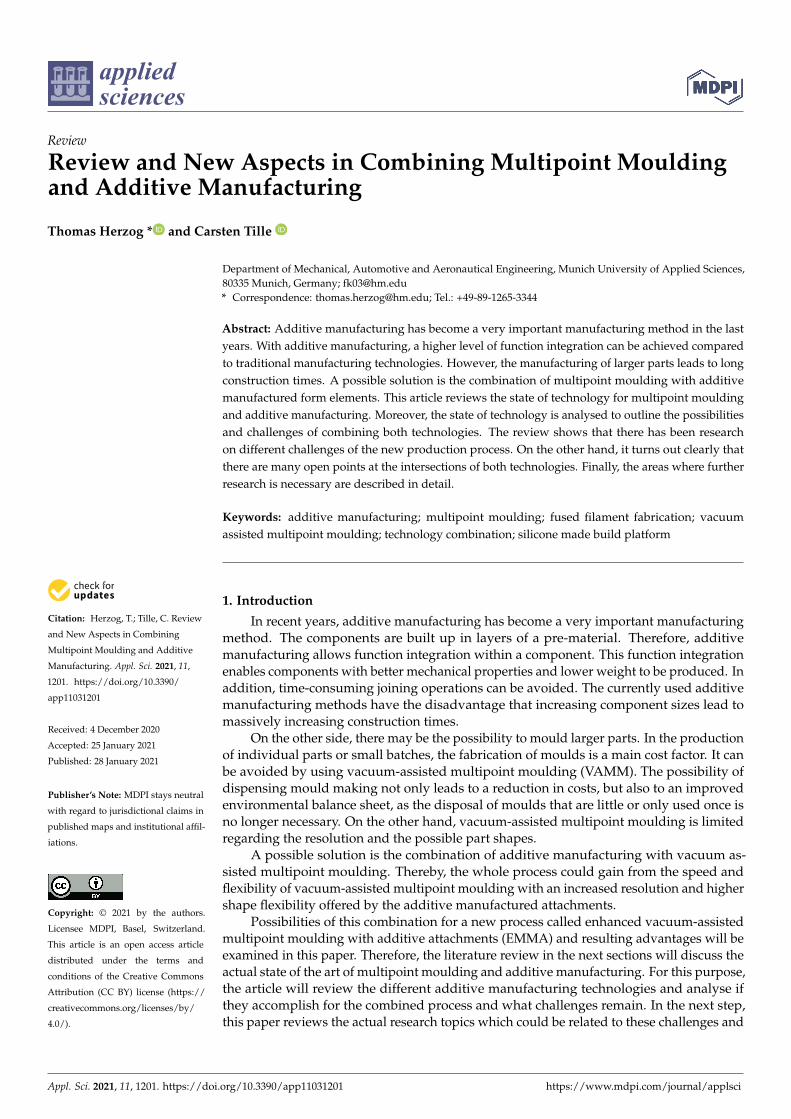
An actual further development was made by WIMMER et al. [23] relying on a denselypacked pin field with vacuum support to enable forming of concave carbon fibre-reinforcedplastic (CFRP) components (see Figure 3). Figure 3 shows that the concept used by WIMMER
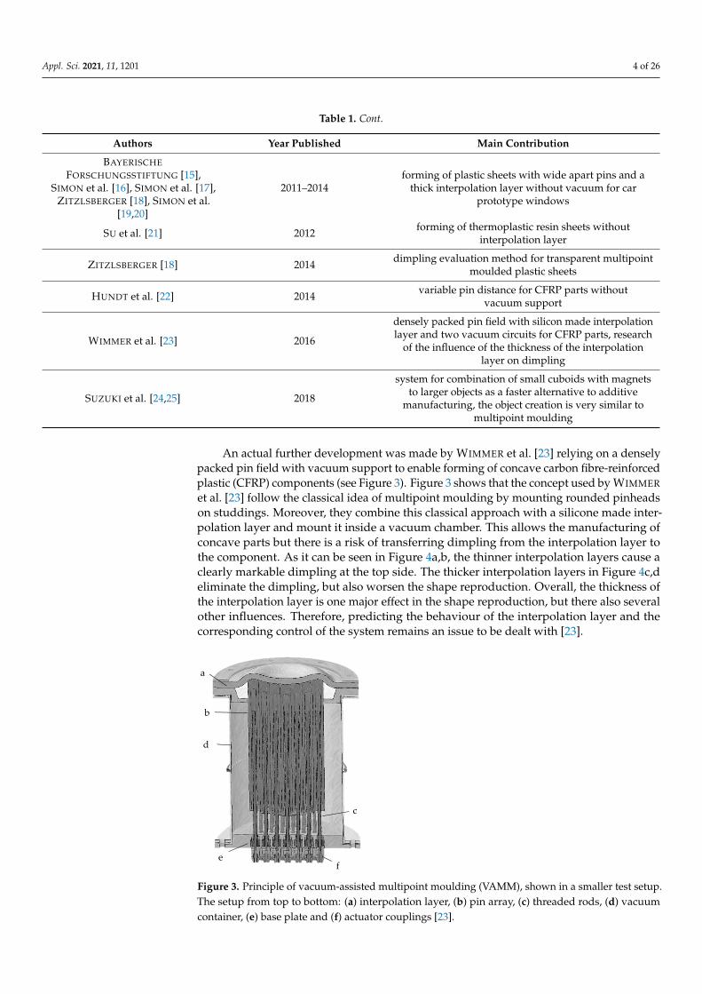
et al. [23] follow the classical idea of multipoint moulding by mounting rounded pinheadson studdings. Moreover, they combine this classical approach with a silicone made inter-polation layer and mount it inside a vacuum chamber. This allows the manufacturing ofconcave parts but there is a risk of transferring dimpling from the interpolation layer tothe component. As it can be seen in Figure 4a,b, the thinner interpolation layers cause aclearly markable dimpling at the top side. The thicker interpolation layers in Figure 4c,deliminate the dimpling, but also worsen the shape reproduction. Overall, the thickness ofthe interpolation layer is one major effect in the shape reproduction, but there also severalother influences. Therefore, predicting the behaviour of the interpolation layer and thecorresponding control of the system remains an issue to be dealt with [23].
Appl. Sci. 2021, 11, x FOR PEER REVIEW 4 of 26
SU et al. [21] 2012 forming of thermoplastic resin sheets without interpolation layer
ZITZLSBERGER [18] 2014 dimpling evaluation method for transparent multipoint moulded plastic sheets
HUNDT et al. [22] 2014 variable pin distance for CFRP parts without vacuum support
WIMMER et al. [23] 2016
densely packed pin field with silicon made interpolation layer and two vacuum circuits for CFRP parts, research of the influence of the thickness of the interpolation layer on
dimpling
SUZUKI et al. [24,25] 2018
system for combination of small cuboids with magnets to larger objects as a faster alternative to additive
manufacturing, the object creation is very similar to multipoint moulding
An actual further development was made by WIMMER et al. [23] relying on a densely packed pin field with vacuum support to enable forming of concave carbon fibre-reinforced plastic (CFRP) components (see Figure 3). Figure 3 shows that the concept used by WIMMER et al. [23] follow the classical idea of multipoint moulding by mounting rounded pinheads on studdings. Moreover, they combine this classical approach with a silicone made interpolation layer and mount it inside a vacuum chamber. This allows the manufacturing of concave parts but there is a risk of transferring dimpling from the interpolation layer to the component. As it can be seen in Figure 4a,b, the thinner interpolation layers cause a clearly markable dimpling at the top side. The thicker interpolation layers in Figure 4c,d eliminate the dimpling, but also worsen the shape reproduction. Overall, the thickness of the interpolation layer is one major effect in the shape reproduction, but there also several other influences. Therefore, predicting the behaviour of the interpolation layer and the corresponding control of the system remains an issue to be dealt with [23].
Figure 3. Principle of vacuum-assisted multipoint moulding (VAMM), shown in a smaller test setup. The setup from top to bottom: (a) interpolation layer, (b) pin array, (c) threaded rods, (d) vacuum container, (e) base plate and (f) actuator couplings [23].
a
b
c
d
e f
Figure 3. Principle of vacuum-assisted multipoint moulding (VAMM), shown in a smaller test setup.The setup from top to bottom: (a) interpolation layer, (b) pin array, (c) threaded rods, (d) vacuumcontainer, (e) base plate and (f) actuator couplings [23].
Appl. Sci. 2021, 11, 1201 5 of 26Appl. Sci. 2021, 11, x FOR PEER REVIEW 5 of 26
Figure 4. 3D scans of bowl shape created with a silicon rubber interpolation layer (40 Shore-A) with varying thickness ((a) 5 mm, (b) 10 mm, (c) 15 mm and (d) 20 mm) at a vacuum of 100 hPa [23].
Vacuum-assisted multipoint moulding according to WIMMER et al. [23] constitutes the basis for the further analysis as being the actual state of technology.
2.2. Restrictions and Solutions Overall, it was shown that this technology has a broad field of application in various
forming processes. Particularly in single-part and small-batch production, the time-consuming and expensive production of moulds can be dispensed. On the other hand, there are still various restrictions.
WIMMER et al. [23] show that size and shape of the pins as well as the interpolation layer used result in a certain resolution of the system. This means that, depending on these parameters, the structure manufactured on the plant must have a minimum size. Another limitation results from the maximum deformability of the interpolation layer, therefore two adjacent pins must not exceed a certain maximum height difference in order not to damage the interpolation layer. This in turn means that sharp-edged transitions cannot be represented.
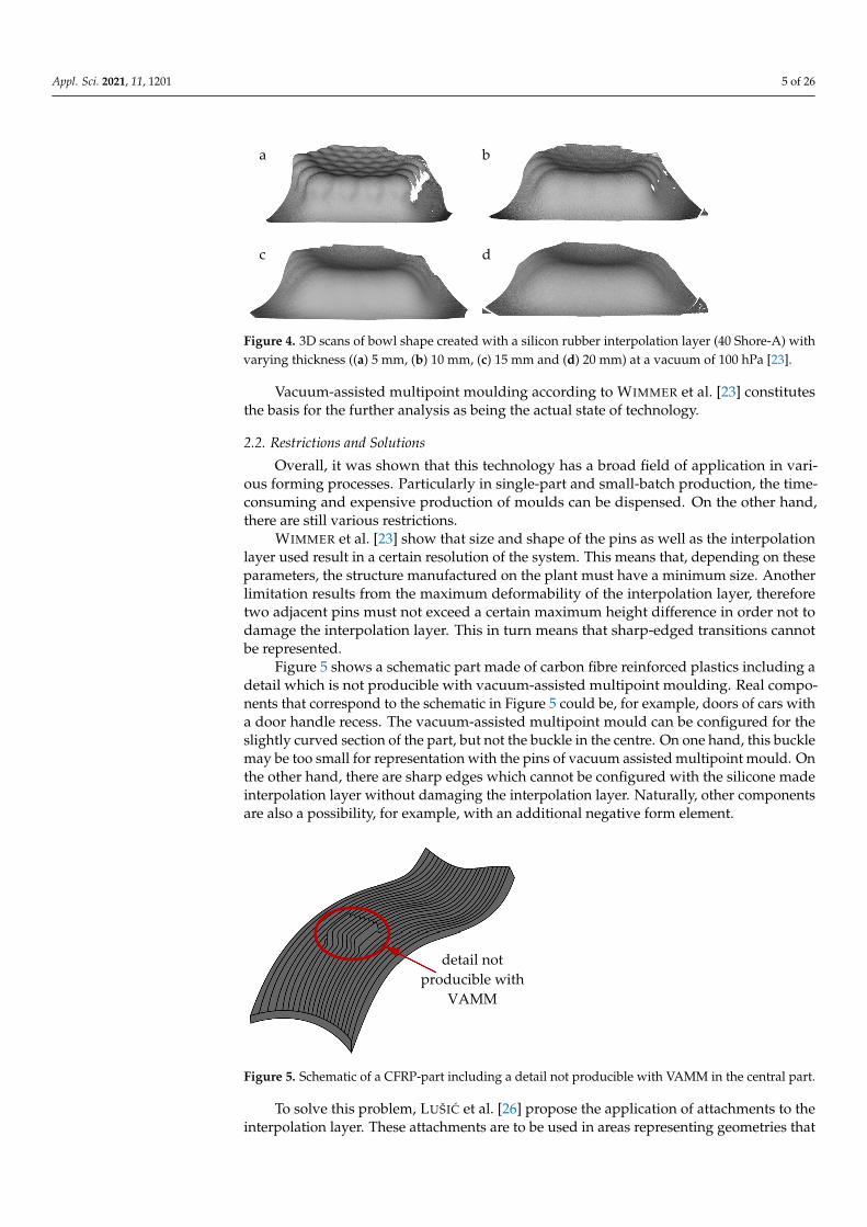
Figure 5 shows a schematic part made of carbon fibre reinforced plastics including a detail which is not producible with vacuum-assisted multipoint moulding. Real components that correspond to the schematic in Figure 5 could be, for example, doors of cars with a door handle recess. The vacuum-assisted multipoint mould can be configured for the slightly curved section of the part, but not the buckle in the centre. On one hand, this buckle may be too small for representation with the pins of vacuum assisted multipoint mould. On the other hand, there are sharp edges which cannot be configured with the silicone made interpolation layer without damaging the interpolation layer. Naturally, other components are also a possibility, for example, with an additional negative form element.
Figure 5. Schematic of a CFRP-part including a detail not producible with VAMM in the central part.
a b
c d
detail not producible with
VAMM
Figure 4. 3D scans of bowl shape created with a silicon rubber interpolation layer (40 Shore-A) withvarying thickness ((a) 5 mm, (b) 10 mm, (c) 15 mm and (d) 20 mm) at a vacuum of 100 hPa [23].
Vacuum-assisted multipoint moulding according to WIMMER et al. [23] constitutesthe basis for the further analysis as being the actual state of technology.
2.2. Restrictions and Solutions
Overall, it was shown that this technology has a broad field of application in vari-ous forming processes. Particularly in single-part and small-batch production, the time-consuming and expensive production of moulds can be dispensed. On the other hand,there are still various restrictions.
WIMMER et al. [23] show that size and shape of the pins as well as the interpolationlayer used result in a certain resolution of the system. This means that, depending on theseparameters, the structure manufactured on the plant must have a minimum size. Anotherlimitation results from the maximum deformability of the interpolation layer, thereforetwo adjacent pins must not exceed a certain maximum height difference in order not todamage the interpolation layer. This in turn means that sharp-edged transitions cannotbe represented.
Figure 5 shows a schematic part made of carbon fibre reinforced plastics including adetail which is not producible with vacuum-assisted multipoint moulding. Real compo-nents that correspond to the schematic in Figure 5 could be, for example, doors of cars witha door handle recess. The vacuum-assisted multipoint mould can be configured for theslightly curved section of the part, but not the buckle in the centre. On one hand, this bucklemay be too small for representation with the pins of vacuum assisted multipoint mould. Onthe other hand, there are sharp edges which cannot be configured with the silicone madeinterpolation layer without damaging the interpolation layer. Naturally, other componentsare also a possibility, for example, with an additional negative form element.
Appl. Sci. 2021, 11, x FOR PEER REVIEW 5 of 26
Figure 4. 3D scans of bowl shape created with a silicon rubber interpolation layer (40 Shore-A) with varying thickness ((a) 5 mm, (b) 10 mm, (c) 15 mm and (d) 20 mm) at a vacuum of 100 hPa [23].
Vacuum-assisted multipoint moulding according to WIMMER et al. [23] constitutes the basis for the further analysis as being the actual state of technology.
2.2. Restrictions and Solutions Overall, it was shown that this technology has a broad field of application in various
forming processes. Particularly in single-part and small-batch production, the time-consuming and expensive production of moulds can be dispensed. On the other hand, there are still various restrictions.
WIMMER et al. [23] show that size and shape of the pins as well as the interpolation layer used result in a certain resolution of the system. This means that, depending on these parameters, the structure manufactured on the plant must have a minimum size. Another limitation results from the maximum deformability of the interpolation layer, therefore two adjacent pins must not exceed a certain maximum height difference in order not to damage the interpolation layer. This in turn means that sharp-edged transitions cannot be represented.
Figure 5 shows a schematic part made of carbon fibre reinforced plastics including a detail which is not producible with vacuum-assisted multipoint moulding. Real components that correspond to the schematic in Figure 5 could be, for example, doors of cars with a door handle recess. The vacuum-assisted multipoint mould can be configured for the slightly curved section of the part, but not the buckle in the centre. On one hand, this buckle may be too small for representation with the pins of vacuum assisted multipoint mould. On the other hand, there are sharp edges which cannot be configured with the silicone made interpolation layer without damaging the interpolation layer. Naturally, other components are also a possibility, for example, with an additional negative form element.
Figure 5. Schematic of a CFRP-part including a detail not producible with VAMM in the central part.
a b
c d
detail not producible with
VAMM
Figure 5. Schematic of a CFRP-part including a detail not producible with VAMM in the central part.
To solve this problem, LUŠIC et al. [26] propose the application of attachments to theinterpolation layer. These attachments are to be used in areas representing geometries that

Appl. Sci. 2021, 11, 1201 6 of 26
cannot be mapped on the vacuum-assisted multipoint mould. As shown in Figure 6, thisconcept consists of the classical vacuum-assisted multipoint mould approach with the pinsmounted in a vacuum chamber and a flexible interpolation layer at the top. On top of theinterpolation layer an additive manufactured attachment is mounted to build the detailwhich cannot be represented by the vacuum assisted multipoint mould. The fixing of theexternally manufactured attachments on the interpolation layer is identified as a problem.Three different solutions are presented, two of them are types of vacuum mounting andthe third is a needle mounting system.
Appl. Sci. 2021, 11, x FOR PEER REVIEW 6 of 26
To solve this problem, LUŠIĆ et al. [26] propose the application of attachments to the interpolation layer. These attachments are to be used in areas representing geometries that cannot be mapped on the vacuum-assisted multipoint mould. As shown in Figure 6, this concept consists of the classical vacuum-assisted multipoint mould approach with the pins mounted in a vacuum chamber and a flexible interpolation layer at the top. On top of the interpolation layer an additive manufactured attachment is mounted to build the detail which cannot be represented by the vacuum assisted multipoint mould. The fixing of the externally manufactured attachments on the interpolation layer is identified as a problem. Three different solutions are presented, two of them are types of vacuum mounting and the third is a needle mounting system.
Figure 6. Enhanced vacuum-assisted multipoint moulding with additive attachments, consisting of the vacuum-assisted multipoint mould with pins and interpolation layer and the additive manufactured attachment mounted on top of the interpolation layer.
The combination of the vacuum-assisted multipoint moulding and the additive manufactured attachments has the opportunity to combine a fast moulding process with the possibility for smaller details without producing a mould. Building the whole part with additive manufacturing processes would consume a lot of time, although the parts are thin-walled. On the other hand, the construction and milling of a mould needs even more time, even if the moulding process itself is fast. When combining the vacuum assisted multipoint moulding with additive manufactured attachments on one side the additive manufactured parts are relatively small and thus can be manufactured in a short period of time. On the other side, when using the vacuum-assisted multipoint mould there is no mould-milling necessary which significantly reduces the time required. The positioning problem of these attachments on the vacuum assisted multipoint mould is not completely solved. If a manual positioning is carried out, deviations in dimensional accuracy can be expected. In addition, trained employees are needed for manual steps, which generally reduce the efficiency of the technology. A further aspect is the need to pick up the surface in order to be able to produce precisely matching attachments. It is therefore desirable to aim for a continuous production process directly integrated in one plant and delivering a finished mould, based on the digital computer-aided design (CAD) model. Consequently, this paper will only focus on production processes matching these requirements.
Figure 7 shows the process flow chart for the proclaimed enhanced vacuum-assisted multipoint moulding with additive attachments process. It starts with the CAD model of part to be manufactured followed by the separation of the geometries in the parts which are manufacturable by the vacuum assisted multipoint moulding itself und the parts where additive attachments are needed. In the next steps, the data for the adjustment of
Pins
additive manufactured attachment
interpolation layer
vacuum assisted multipoint mould
additive manufactured attachment interpolation layer
vacuum assisted multipoint mould pins
Figure 6. Enhanced vacuum-assisted multipoint moulding with additive attachments, consisting ofthe vacuum-assisted multipoint mould with pins and interpolation layer and the additive manufac-tured attachment mounted on top of the interpolation layer.
The combination of the vacuum-assisted multipoint moulding and the additive man-ufactured attachments has the opportunity to combine a fast moulding process with thepossibility for smaller details without producing a mould. Building the whole part withadditive manufacturing processes would consume a lot of time, although the parts arethin-walled. On the other hand, the construction and milling of a mould needs even moretime, even if the moulding process itself is fast. When combining the vacuum assistedmultipoint moulding with additive manufactured attachments on one side the additivemanufactured parts are relatively small and thus can be manufactured in a short periodof time. On the other side, when using the vacuum-assisted multipoint mould there is nomould-milling necessary which significantly reduces the time required. The positioningproblem of these attachments on the vacuum assisted multipoint mould is not completelysolved. If a manual positioning is carried out, deviations in dimensional accuracy can beexpected. In addition, trained employees are needed for manual steps, which generallyreduce the efficiency of the technology. A further aspect is the need to pick up the surfacein order to be able to produce precisely matching attachments. It is therefore desirable toaim for a continuous production process directly integrated in one plant and delivering afinished mould, based on the digital computer-aided design (CAD) model. Consequently,this paper will only focus on production processes matching these requirements.
Figure 7 shows the process flow chart for the proclaimed enhanced vacuum-assistedmultipoint moulding with additive attachments process. It starts with the CAD model ofpart to be manufactured followed by the separation of the geometries in the parts whichare manufacturable by the vacuum assisted multipoint moulding itself und the parts whereadditive attachments are needed. In the next steps, the data for the adjustment of thevacuum-assisted multipoint mould have to be calculated followed by the adjustment itself.If the vacuum-assisted multipoint mould is adjusted accordingly to the target geometrythe manufacturing data for the additive attachments can be calculated and sliced, followedby the manufacturing of these attachments the part can be moulded.

Appl. Sci. 2021, 11, 1201 7 of 26
Appl. Sci. 2021, 11, x FOR PEER REVIEW 7 of 27
part to be manufactured followed by the separation of the geometries in the parts which are manufacturable by the vacuum assisted multipoint moulding itself und the parts where additive attachments are needed. In the next steps, the data for the adjustment of the vacuum-assisted multipoint mould have to be calculated followed by the adjustment itself. If the vacuum-assisted multipoint mould is adjusted accordingly to the target geometry the manufacturing data for the additive attachments can be calculated and sliced, followed by the manufacturing of these attachments the part can be moulded.
Figure 7. Process flow chart for enhanced vacuum assisted multipoint moulding with additive attachments.
Therefore, the next section will provide an overview of the actual state of the art in additive manufacturing technologies and discuss them in respect to combine both technologies.
3. Possible Additive Manufacturing Methods
Figure 7. Process flow chart for enhanced vacuum assisted multipoint moulding with additive attachments.
Therefore, the next section will provide an overview of the actual state of the artin additive manufacturing technologies and discuss them in respect to combine bothtechnologies.
3. Possible Additive Manufacturing Methods
According to BRANS [27], additive manufacturing processes have been known fora long time and were already used in special applications and in prototype constructionin the past. However, it has not become possible to use additive manufacturing in com-ponent production until the further development of the technology and its expansion tovarious materials.
The additive manufacturing processes, commonly known as 3D printing, are in mostcases not based on a true three-dimensional production of the components, but use a 2.5Dapproach. With this approach, the three-dimensional component to be created is cut intoindividual layers with a constant thickness. These layers are stacked along the buildingdirection (see Figure 8). A change of the geometry, for example, the wall thickness, can onlytake place in the transition of two layers. As it can be seen in Figure 8, this approach leadsto a loss of details on one hand and to a staircase effect in the other hand. However, thismethod makes it possible to produce components with geometries that cannot be producedusing conventional fabrication methods and therefore would have to be joined from severalparts. In turn, this functional integration makes it possible to save joining processes andthus reduce production costs [28].

Appl. Sci. 2021, 11, 1201 8 of 26
Appl. Sci. 2021, 11, x FOR PEER REVIEW 8 of 26
The additive manufacturing processes, commonly known as 3D printing, are in most cases not based on a true three-dimensional production of the components, but use a 2.5D approach. With this approach, the three-dimensional component to be created is cut into individual layers with a constant thickness. These layers are stacked along the building direction (see Figure 8). A change of the geometry, for example, the wall thickness, can only take place in the transition of two layers. As it can be seen in Figure 8, this approach leads to a loss of details on one hand and to a staircase effect in the other hand. However, this method makes it possible to produce components with geometries that cannot be produced using conventional fabrication methods and therefore would have to be joined from several parts. In turn, this functional integration makes it possible to save joining processes and thus reduce production costs [28].
Figure 8. Slicing scheme for flat layers in additive manufacturing. Model with marked layers (left) and derived layer model (right).
In this section, the most common processes are presented and their suitability for the new enhanced vacuum-assisted multipoint moulding with additive attachments outlined in this paper is assessed.
3.1. Metal Based Processes The historically newer group are additive manufacturing processes that use metals
as manufacturing material. FRAZIER [29] already offers a comprehensive overview of the current opportunities of these processes, so that only a brief overview is to be provided here.
In this group, commonly used systems are based on a powder bed. The main principle is to build up a powder bed and fuse the powder using a laser beam directed by X-Y scanning mirrors. The component is then covered with a further layer of powder by the powder levelling roller that is fused to the underlying layer by the laser beam (see Figure 9). These processes are called laser powder bed fusion respectively selective laser melting [30].
A similar process is directed energy deposition, in which a laser beam is guided along the contour of the component while a nozzle is used to blow metal powder to the laser beam continuously (see Figure 10). The laser beam melts the powder and the component can be built up. At the same time, a powder bed is not necessary, reducing powder consumption. However, there is a high energy input into the build plate [31,32].
Figure 8. Slicing scheme for flat layers in additive manufacturing. Model with marked layers (left)and derived layer model (right).
In this section, the most common processes are presented and their suitability for thenew enhanced vacuum-assisted multipoint moulding with additive attachments outlinedin this paper is assessed.
3.1. Metal Based Processes
The historically newer group are additive manufacturing processes that use metalsas manufacturing material. FRAZIER [29] already offers a comprehensive overview of thecurrent opportunities of these processes, so that only a brief overview is to be provided here.
In this group, commonly used systems are based on a powder bed. The main principleis to build up a powder bed and fuse the powder using a laser beam directed by X-Yscanning mirrors. The component is then covered with a further layer of powder by thepowder levelling roller that is fused to the underlying layer by the laser beam (see Figure 9).These processes are called laser powder bed fusion respectively selective laser melting [30].
Appl. Sci. 2021, 11, x FOR PEER REVIEW 9 of 26
Figure 9. Schematic representation of laser powder bed fusion (based on the work in [30]).
Figure 10. Schematic representation of directed energy deposition (based on the work in [29]).
SAENDIG et al. [33,34] and TECHEL et al. [35] introduce a process in which the layers of individual metal plates are cut out by laser and then get welded together. According to GEBHARDT [28], this form of laminating object modelling was not successful on the market.
An alternative method is the bonding of the powder by a binder in the binder jetting process, which was introduced by SACHS et al. [36] for metallic and ceramic parts. A powder bed is built up in layers similar to laser powder bed fusion. However, the individual grains are not joined by welding with a laser, but by bonding. The adhesive is sprayed onto the powder layer by layer to build up the geometry. The nozzles used are identical or very similar in construction to the print heads known from inkjet printing, which are usually guided and moved via a portal. Synthetic resins are often used as
laser X-Y scanning mirrors
laser beam powder bed
build platform
feed cartridge
powder levelling roller
laser beam guidance system
carrier gas
lens
deposition head
AM deposit
powder supply
Figure 9. Schematic representation of laser powder bed fusion (based on the work in [30]).
A similar process is directed energy deposition, in which a laser beam is guided alongthe contour of the component while a nozzle is used to blow metal powder to the laser beamcontinuously (see Figure 10). The laser beam melts the powder and the component can be

Appl. Sci. 2021, 11, 1201 9 of 26
built up. At the same time, a powder bed is not necessary, reducing powder consumption.However, there is a high energy input into the build plate [31,32].
Appl. Sci. 2021, 11, x FOR PEER REVIEW 9 of 26
Figure 9. Schematic representation of laser powder bed fusion (based on the work in [30]).
Figure 10. Schematic representation of directed energy deposition (based on the work in [29]).
SAENDIG et al. [33,34] and TECHEL et al. [35] introduce a process in which the layers of individual metal plates are cut out by laser and then get welded together. According to GEBHARDT [28], this form of laminating object modelling was not successful on the market.
An alternative method is the bonding of the powder by a binder in the binder jetting process, which was introduced by SACHS et al. [36] for metallic and ceramic parts. A powder bed is built up in layers similar to laser powder bed fusion. However, the individual grains are not joined by welding with a laser, but by bonding. The adhesive is sprayed onto the powder layer by layer to build up the geometry. The nozzles used are identical or very similar in construction to the print heads known from inkjet printing, which are usually guided and moved via a portal. Synthetic resins are often used as
laser X-Y scanning mirrors
laser beam powder bed
build platform
feed cartridge
powder levelling roller
laser beam guidance system
carrier gas
lens
deposition head
AM deposit
powder supply
Figure 10. Schematic representation of directed energy deposition (based on the work in [29]).
SAENDIG et al. [33,34] and TECHEL et al. [35] introduce a process in which the layersof individual metal plates are cut out by laser and then get welded together. According toGEBHARDT [28], this form of laminating object modelling was not successful on the market.
An alternative method is the bonding of the powder by a binder in the binder jettingprocess, which was introduced by SACHS et al. [36] for metallic and ceramic parts. Apowder bed is built up in layers similar to laser powder bed fusion. However, the individualgrains are not joined by welding with a laser, but by bonding. The adhesive is sprayedonto the powder layer by layer to build up the geometry. The nozzles used are identicalor very similar in construction to the print heads known from inkjet printing, which areusually guided and moved via a portal. Synthetic resins are often used as adhesives,which are available not only colourless, but also in various colours, making multi-colouredcomponents possible. In case of using metal powder in the first step, a green part isbuilt. In a second process step, the green part is debindered and infiltrated into a densemetal component [28].
3.2. Plastic-Based Processes
In addition to additive manufacturing processes using metals, there is the verywidespread group of processes based on plastics. These processes can be classified ac-cording to the shape of the starting material. They can be divided into powder bedprocesses, extrusion processes, resin bath processes and processes using plate- or film-likestarting materials.
In the field of powder bed processes, selective laser sintering is available in analogyto laser powder bed fusion with metals. However, the construction chamber is heatedand maintained just below the melting point or the glass transition temperature of theplastic powder. This significantly reduces the energy to be introduced by the laser andprevents distortion. To suppress oxidation processes and the associated degradation of thematerial, the process is carried out in a nitrogen atmosphere. The layer thickness is about0.1 mm [30].

Appl. Sci. 2021, 11, 1201 10 of 26
The widely used fused layer modelling originates from the field of extrusion processes.This method is often mistakenly referred to as fused deposition modelling. Due to the com-paratively simple design of the devices and the possible placement at the workplace, thisprocedure has become established for home users. Nevertheless, there are also devices forcommercial use with an extended range of functions. In most cases, the solid thermoplasticraw material is pressed through a heated nozzle and liquefied. This liquid extrudate isplaced next to each other on one level to produce the individual layer and in several layerson top of each other to produce the actual component. In most cases, a filament is usedas the raw material, which is fed directly from a coil to the nozzle. Therefore, the morespecific name fused filament fabrication (see Figure 11) is often used. Rarely pellet rawmaterial is applied, which is liquefied in a screw extruder. In most cases, fused filamentfabrication is used with a heated build plate to reduce warping, deformation and facilitatea better adhesion between the first layer and the build plate. Whereas other additivemanufacturing technologies are very material specific there are many materials availablefor fused layer modelling [28].
Appl. Sci. 2021, 11, x FOR PEER REVIEW 10 of 26
adhesives, which are available not only colourless, but also in various colours, making multi-coloured components possible. In case of using metal powder in the first step, a green part is built. In a second process step, the green part is debindered and infiltrated into a dense metal component [28].
3.2. Plastic-Based Processes In addition to additive manufacturing processes using metals, there is the very
widespread group of processes based on plastics. These processes can be classified according to the shape of the starting material. They can be divided into powder bed processes, extrusion processes, resin bath processes and processes using plate- or film-like starting materials.
In the field of powder bed processes, selective laser sintering is available in analogy to laser powder bed fusion with metals. However, the construction chamber is heated and maintained just below the melting point or the glass transition temperature of the plastic powder. This significantly reduces the energy to be introduced by the laser and prevents distortion. To suppress oxidation processes and the associated degradation of the material, the process is carried out in a nitrogen atmosphere. The layer thickness is about 0.1 mm [30].
The widely used fused layer modelling originates from the field of extrusion processes. This method is often mistakenly referred to as fused deposition modelling. Due to the comparatively simple design of the devices and the possible placement at the workplace, this procedure has become established for home users. Nevertheless, there are also devices for commercial use with an extended range of functions. In most cases, the solid thermoplastic raw material is pressed through a heated nozzle and liquefied. This liquid extrudate is placed next to each other on one level to produce the individual layer and in several layers on top of each other to produce the actual component. In most cases, a filament is used as the raw material, which is fed directly from a coil to the nozzle. Therefore, the more specific name fused filament fabrication (see Figure 11) is often used. Rarely pellet raw material is applied, which is liquefied in a screw extruder. In most cases, fused filament fabrication is used with a heated build plate to reduce warping, deformation and facilitate a better adhesion between the first layer and the build plate. Whereas other additive manufacturing technologies are very material specific there are many materials available for fused layer modelling [28].
Figure 11. Schematic representation of fused filament fabrication (based on the work in [37]).
In addition to the often-used plastics, also gel-like or liquid materials are used, for example, in medical applications. LI et al. [38] present such a procedure for direct skin reconstruction.
filament
extruder with nozzle
build
ing
dire
ctio
n
building platform
fibre
Figure 11. Schematic representation of fused filament fabrication (based on the work in [37]).
In addition to the often-used plastics, also gel-like or liquid materials are used, for example,in medical applications. LI et al. [38] present such a procedure for direct skin reconstruction.
Despite the relatively high degree of diffusion of the technology, many questions stillneed to be clarified scientifically. These are often questions concerning the optimisationof process parameters to improve production quality. DONG et al. [39] optimise the mainprocess parameters to enable and improve the production of lattice structures. They showa clear influence on the manufacturability of the components, on the one hand, and on themechanical properties of the component on the other. Apart from that, ERTAY et al. [40]address the problem of sharp directional changes in the extrusion path. These changesin direction lead to accumulation of material if the extrusion rate remains unchanged asthe tangential speed of the die is greatly reduced relative to the build platform. Therefore,ERTAY et al. [40] develop a control algorithm that leads to a more uniform material deposi-tion rate and thus to more precise components by influencing the extrusion parameters.LUZANIN et al. [41], on the other hand, optimise process parameters for polylactide (PLA)components with the aim of achieving the greatest possible bending strength.
Another major factor influencing the component strength of fused filament fabricationcomponents is the connection between the individual extrusion strands within the layer orbetween the layers. Based on empirical data COOGAN AND KAZMER [37] clearly show thatthe component strength along the extrusion strands is significantly higher than the strengthacross extrusion direction. For a better prediction of this anisotropic behaviour, COOGAN
AND KAZMER [42] develop a simulation model of the connection between the extrusionstrands. CANTRELL et al. [43] and KELES et al. [44] can also determine a clear dependenceof the mechanical characteristics on the position of the component in the building space.

Appl. Sci. 2021, 11, 1201 11 of 26
SEIDL et al. [45] compare the mechanical properties of the components produced by fusedfilament fabrication with those of components produced by injection moulding. Theconclusion is that the additively manufactured components achieve strengths close to thoseof the injection-moulded components along the extrusion strands. In contrast, componentsproduced using fused filament fabrication perform significantly worse under bendingstress. RAUT et al. [46] extend the strength approach by the aspect of construction costs andtry to derive an optimum from it. LIU AND YU [47] make targeted use of this anisotropy andshow a formalism for the targeted reinforcement of highly stressed areas by correspondingplanning of the extrusion paths. MOHAMED et al. [48] identify not only the screen angle, butalso the layer thickness, the nozzle spacing and the number of contour paths as importantfactors influencing creep resistance. PRATER et al. [49] show that components producedin weightlessness have significantly better mechanical properties than those produced onearth. The exact reasons for this behaviour remain unclear.
The group of stereolithographic processes (SLA) rely on a liquid and light-sensitiveresin as a base material. As shown in Figure 12a, one option is to use a laser beam forexposing a construction chamber filled with liquid resin along the component contours andthus activating the solidification of the polymer in these areas. Alternatively, the contoursof an entire layer are exposed to light and thus cured by a mask process, as shown inFigure 12b. In the next step, the construction platform is lowered and the next layer iscreated. This process achieves very high accuracies and especially the mask processesachieve good production speeds. The downside is that in the first process step only greenparts are produced which have to be cured afterwards [28,30].
The laminated layer manufacturing (LLM) or laminated object modelling (LOM) (seeFigure 13) has to be mentioned as a process with plate- or film-shaped raw materials. Foreach layer of the part, a new film layer is glued to the lower layer and cut out along thecomponent contours. The produced part can be removed from the waste material hackledby a crosshatch after all layers have been produced [28,30].
Appl. Sci. 2021, 11, x FOR PEER REVIEW 12 of 26
Figure 12. Schematic representation of stereolithographic processes: (a) vector scan SLA, (b) mask projection SLA (based
on [30]).
The laminated layer manufacturing (LLM) or laminated object modelling (LOM) (see
Figure 13) has to be mentioned as a process with plate- or film-shaped raw materials. For
each layer of the part, a new film layer is glued to the lower layer and cut out along the
component contours. The produced part can be removed from the waste material hackled
by a crosshatch after all layers have been produced [28,30].
Figure 13. Schematic representation of laminated layer manufacturing (based on [50]).
However, the disadvantage is that the individual film layers create clearly visible and
comparatively sharp-edged transitions between the layers on component slopes, the so-
called staircase effect. For a significant increase in production speed and simultaneous
improvement in surface quality HOPE et al. [51], HOPE et al. [52], LEE et al. [53] and LEE et
al. [54] present a process based on thicker layers. At the same time, a cut deviating from
the vertical is made possible, so that the staircase effect can be reduced.
3.3. Processes for Other Materials
In addition to the methods already presented, there are adapted or proprietary
processes for many other materials. Binder jetting is also available for sand and other
materials as base material. A special application for the sand-based process is the foundry
industry, where binder jetting is used to produce cores for moulds quickly and cheaply
(b)
laser
optics
scanning galvanometers
construction chamber
platform
(a) Digital Micro-
Mirror Device™
laser or lamp
optics
laser
optics X-Y positioning device
layer outline and crosshatch
sheet material
material
supply roll platform
part block
take-up roll
Figure 12. Schematic representation of stereolithographic processes: (a) vector scan SLA, (b) mask projection SLA(based on [30]).

Appl. Sci. 2021, 11, 1201 12 of 26
Appl. Sci. 2021, 11, x FOR PEER REVIEW 12 of 26
Figure 12. Schematic representation of stereolithographic processes: (a) vector scan SLA, (b) mask projection SLA (based on [30]).
The laminated layer manufacturing (LLM) or laminated object modelling (LOM) (see Figure 13) has to be mentioned as a process with plate- or film-shaped raw materials. For each layer of the part, a new film layer is glued to the lower layer and cut out along the component contours. The produced part can be removed from the waste material hackled
28 ,30by a crosshatch after all layers have been produced [ ].
Figure 13. Schematic representation of laminated layer manufacturing (based on [50]).
However, the disadvantage is that the individual film layers create clearly visible and comparatively sharp-edged transitions between the layers on component slopes, the so-called staircase effect. For a significant increase in production speed and simultaneous improvement in surface quality HOPE et al. [51], HOPE et al. [52], LEE et al. [53] and LEE et al. [54] present a process based on thicker layers. At the same time, a cut deviating from the vertical is made possible, so that the staircase effect can be reduced.
3.3. Processes for Other Materials In addition to the methods already presented, there are adapted or proprietary
processes for many other materials. Binder jetting is also available for sand and other materials as base material. A special application for the sand-based process is the foundry industry, where binder jetting is used to produce cores for moulds quickly and cheaply without an expensive and time-consuming production of a mould for a core shooter 28 ,30[ ].
(b)
laser
optics scanning
galvanometers
construction chamber
platform
(a) Digital Micro- Mirror
Device™
laser or lamp
optics
laser optics X-Y positioning
device
layer outline and crosshatch
sheet material
material
platform
part block
take-up roll
Figure 13. Schematic representation of laminated layer manufacturing (based on [50]).
However, the disadvantage is that the individual film layers create clearly visibleand comparatively sharp-edged transitions between the layers on component slopes, theso-called staircase effect. For a significant increase in production speed and simultaneousimprovement in surface quality HOPE et al. [51], HOPE et al. [52], LEE et al. [53] and LEE
et al. [54] present a process based on thicker layers. At the same time, a cut deviating fromthe vertical is made possible, so that the staircase effect can be reduced.
3.3. Processes for Other Materials
In addition to the methods already presented, there are adapted or proprietary pro-cesses for many other materials. Binder jetting is also available for sand and other materialsas base material. A special application for the sand-based process is the foundry industry,where binder jetting is used to produce cores for moulds quickly and cheaply without anexpensive and time-consuming production of a mould for a core shooter [28,30].
JUNK AND CÔTÉ [55,56] also found in a comparative study that the energy balance ofbinder jetting is significantly better than that of fused filament fabrication. It was foundthat the energy consumption for building a test prototype in the binder jetting process issignificantly lower. The most important factor influencing energy consumption was theconstruction time.
The fused filament fabrication has been further developed too. There are manyversions for a wide variety of materials. LIM et al. [57] present a version of fused layermodelling for the production of large curved concrete parts. BELLINI [58], on the otherhand, is developing a process for the extrusion of ceramic components. AN et al. [59]show in an overview of the current state of research that the fused filament fabricationis also interesting for the production of organic components. Current research rangesfrom the production of replacements for missing skin areas to the extrusion of tissue forentire organs. Medical technology also deals with additive manufacturing. The idea isusually the possibility of individual adaptation of the parts to the patient’s needs. Forexample, COMOTTI et al. [60] show an approach for the production of a prosthesis of thelower extremities. However, an individually adapted shape is created in a multi-materialapproach, which can be produced in one production step by additive manufacturing.
The laminated layer manufacturing can use paper as a raw material. Thereby, the partis built from individual layers of paper, which are glued together and cut out [28,30].
Summarising the additive manufacturing processes for other materials are mostlyvariants of processes originally using metals or plastics.
3.4. Process Discussion
Table 2 provides an overview of the essential process parameters of the additivemanufacturing processes presented, so that the ideal options for the integrated process canbe discussed further.

Appl. Sci. 2021, 11, 1201 13 of 26
Beside the technical aspects in combining both technologies there are the productioncosts of the process. On one hand, the plant costs and, on the other hand, the productioncosts have to be mentioned. With regard to the production costs of parts manufactured bythe enhanced vacuum-assisted multipoint moulding with additive attachments process, thelargest part is related to the manufacturing costs of the additive manufactured attachments.Therefore, the comparison of the production costs with the different additive manufacturingprocesses would be a very interesting topic. There is a lot of literature on this subject, forexample, COSTABILE et al. [61], or DOUGLAS [62], offer an overview on calculating additivemanufacturing costs. As it can be seen there, the calculation of the real costs is very complexand provides very different values depending on the specific machine manufacturer andmaterial supplier. Therefore, this factor is excluded from the further research and shouldpossibly be examined again in the future.
The processes for the additive production of metal components rely on metal powder.Powder residues that get into the vacuum-assisted multipoint mould can lead to the failureof the system. This would require a complex sealing against powder dust. On the otherhand, the metal parts provide a good temperature stability and high temperature curingcarbon fibre-reinforced plastics systems can be used. The melting temperatures of themetals are well above the decomposition temperatures of the silicone mats currently usedas interpolation layers. Therefore, the application of the attachments to the interpolationlayer would lead to the destruction of the interpolation layer. In contrast, using the binderjetting process resolves the temperature problem in the first step. In a second step, thegreen parts have to be debindered and sintered, which leads to the same temperatureproblem or to the removal from the interpolation layer with the need of repositioning afterpostprocessing. Therefore, the additive manufacturing processes using metals or alloys arenot suitable for a combined integrated process.

Appl. Sci. 2021, 11, 1201 14 of 26
Table 2. Main characteristics of additive manufacturing processes in respect of the combination with vacuum assisted multipoint moulding.
Process Name Material Form of Base Material Field of ProcessTemperatures Advantages Disadvantages
Laser Powder Bed Fusion (LPBF) metals, alloys powder bedmaterial dependent
(melting spot:600–3500 ◦C)
temperature stability of parts,precision, part strength,
shape options
powder bed, high fusingtemperatures,
residual material
Directed Energy Deposition(DED) metals, alloys powder jet
material dependent(melting spot:600–3500 ◦C)
temperature stability of parts,part strength
powder, high fusingtemperatures,
Laminated Object Modelling(LOM)
metals, alloys, plastics,paper solid plates, film reels depending on material (room
temperature—1500 ◦C)
depending on material, manymaterials available, process at
room temperature possible
staircase effect, residualmaterial, cutting and joining
of material
Binder Jetting (3DP) metals, alloys, ceramics,sand powder bed room temperature
many materials available,part strength, process time,
shape options
possibly postprocessingnecessary, powder bed,
residual material
Selective Laser Sintering (SLS) plastics powder bed
material dependent (buildingchamber: 100–150 ◦C
sintering spot:100–350 ◦C)
precision, shape optionspowder bed, high fusingtemperatures, residual
material, heated chamber
Fused Layer Modelling (FLM) 1 plastics, concrete, biomaterials
filament, pellets, gel-likeliquids
material dependent (roomtemperature—250 ◦C)
no residual material,comparatively simple, only
nozzle heated,many materials
temperature stability of parts,part strength, shape options
Stereolithography (SLA) liquid, light-sensitive resins resin bath 25–30 ◦C, possiblycooling necessary precision, process time
resin bath, temperaturestability of parts, part
strength, shape options,postprocessing needed
1 More commonly known is Fused Filament Fabrication (FFF), as a special case of the process group for the use of filaments as raw material.

Appl. Sci. 2021, 11, 1201 15 of 26
Accordingly, to the metal processes, powder bed processes are only insufficientlysuitable for enhanced vacuum-assisted multipoint moulding with additive attachmentsintegrated in one plant, even when using plastics. As the process temperatures are reducedand may be suitable with the interpolation layer the big advance of the high temperaturestability is also no longer existent. The situation is similar with stereolithographic processesthat rely on a resin bath, which can only be realised directly on the interpolation layer withgreat effort. In contrast, the fused filament fabrication has great potential for enhancedvacuum assisted multipoint moulding with additive attachments, since the material isonly placed at the required points during production. The solid raw material can befed from a coil, so that no special precautions are necessary on the vacuum assistedmultipoint mould. Summarising in the case of plastic processes the powder bed processesand the stereolithographic processes only have little advances in regard to the integratedenhanced vacuum assisted multipoint moulding with additive attachments process. Thebig disadvantage is the high effort in dealing with the powder and resin residuals.
When it comes to other materials the production of sand attachments directly on thevacuum assisted multipoint mould leads to the same problem as with all powder bedprocesses, although sand models would ensure good temperature stability. The extrusionof concrete already shows clear advantages here since no excess material has to be removedyet the penetration of concrete into the vacuum assisted multipoint mould carries risks.Furthermore, the material cannot be stored ready for processing, but would have eitherto be mixed in the process or produced in advance of production. Subsequently, thecomponents require a long setting and curing time until the actual component can bemanufactured. The high temperature stability would be an advantage too. Paper modelswould ensure relatively easy processability, but the model must be impregnated before theinfiltration of the carbon fibre part starts. Otherwise, the paper absorbs the resin of thecomponent to be infiltrated with and adheres to them.
Summarising, there are different possible additive manufacturing methods availablefor the integrated process of enhanced vacuum assisted multipoint moulding with additiveattachments. The fused filament fabrication is clearly the easiest way to implement theprocess, with just one disadvantage which is the relatively low temperature stability of theattachments. Therefore, only resin systems curing at room temperature can be used forthe carbon fibre reinforced plastic parts. Hence, this paper will focus on the combinationof vacuum assisted multipoint moulding with attachments produced by fused filamentfabrication.
Therefore, the next chapter will focus on the different possibilities and difficulties ofintegrating fused filament fabrication to the vacuum assisted multipoint mould.
4. Discussion of the Process Combination in Enhanced Vacuum Assisted MultipointMoulding with Additive Attachments
By default, the fused filament fabrication process is operated with low melting pointplastics and therefore has the disadvantage that only material with low curing or formingtemperatures can be used for part production. In addition, in most cases a glass plate isused as a construction platform for the fused filament fabrication, which inherits a numberof differing properties in comparison to the interpolation layer made of silicone. Moreover,the building platform is usually flat. This means that the curved building ground on thevacuum assisted multipoint mould also represents a deviation from the standard process.
According to KLEESPIES III AND CRAWFORD [63] the discrete pins of the vacuumassisted multipoint mould cause unevenness in the part despite the interpolation layer(see Figure 4). The degree of unevenness the so-called dimpling essentially depends onthe mechanical properties and the thickness of the interpolation layer. However, the useof a thicker interpolation layer results in a significant decrease of the smallest produciblestructure. Hence, an appropriate middle course must be chosen here. While KLEESPIES IIIAND CRAWFORD [63] detect the occurrence of dimpling in the forming of plastic sheets,PĂUNOIU et al. [64] show that this effect also occurs during the forming of sheet metal.Similar influencing parameters are determined in each case. According to LUŠIC et al. [65]

Appl. Sci. 2021, 11, 1201 16 of 26
the compensation of this phenomenon would either be to make the system significantlymore precise and rigid, which would cause high costs. Hence, LUŠIC et al. [65] developa readjustment of the pins based on a 3D measurement of the surface. Therefore, thepins are initially adjusted followed by a three-dimensional scan of the actual shape of theinterpolation layer. This actual shape is matched with the CAD model of the part to beproduced with a best fit method. Based on this match, the deviations of the individualpins are determined and in the next step the VAMM is adjusted accordingly, thus the formdeviations of the VAMM can be reduced.
Another problem of enhanced vacuum assisted multipoint moulding with additiveattachments could arise from the layered manufacturing of the additively produced at-tachments. KULKARNI AND DUTTA [66] clearly show that noticeable surface defects canoccur depending on the layer thickness and the construction angle of the component. Sincethese surface defects resemble a staircase, the effect is also called the staircase effect (seeFigure 8). KULKARNI AND DUTTA [66] develop an adaptive cutting technique to reducethis effect, which adapts the layer height to the shape of the component and thus producessignificantly more precise surface contours. To further improve the prediction of the stair-case effect, VAHABLI AND RAHMATI [67] develop a method based on a neural network andthus achieve a significantly more accurate prediction of the expected surface roughness.KUO et al. [68], on the other hand, show an appropriate post-treatment option by fillingthe steps with epoxy resin. In addition to a significant improvement in surface accuracy, amassive improvement in the mechanical properties of the component can also be achieved.
Overall, the combination of the two processes in enhanced vacuum assisted multipointmoulding with additive attachments is countered on the one hand by the problems ofthe shape deviation of the flexible form. On the other hand, the defects of the additivelyproduced attachments themselves could impair due to the staircase effect. Therefore, thenext step is to examine whether solutions have already been found for these challengesand whether these can be transferred to enhanced vacuum assisted multipoint mouldingwith additive attachments.
4.1. Additive Manufacturing on Silicone Made Building Platform
The aim of current research is to develop enhanced vacuum-assisted multipointmoulding with additive attachments a continuous process for manufacturing with a vac-uum assisted multipoint mould. As already mentioned, it is necessary to place additionaladditively manufactured attachments on the interpolation layer at certain points in orderto be able to map a larger part spectrum. Moreover, it should be possible to adjust themachine without any further intervention by an employee. Therefore, the system must beable to produce the attachments directly in one plant. As the vacuum-assisted multipointmoulding for carbon fibre-reinforced plastics uses a silicone interpolation layer [23], theattachments must be manufactured on a silicone building platform.
In the literature, there are already some processes outlined which produce directlyon existing components and thus deviate from the usual flat building platforms. Amongthe procedures of laser-sintering the method of KESHAV et al. [31,32] should be mentioned.They are developing a metal-based process that uses an inert gas jet to bring metal powderto the point of material application. The powder is melted at its destination by a laser beamand thus bonded to the underlying layer. They are reducing the laser power to minimisethe temperature load on the substrate. Nevertheless, the images show a clear heat influenceon the base material. Therefore, the process is ruled out for an application on silicone.
CHOI et al. [69] present a process resulting from the adaption of a standard fusedfilament fabrication machine. Due to the conversions made to the machine used by them,it is possible to manufacture on already existing components and to consider unevensubsoil structures. The results show that production on existing components is possi-ble, even if these components do not have a flat surface. However, the original compo-nents also consisted of an acrylonitrile butadiene styrene (ABS) or Acrylonitrile butadienestyrene/polycarbonate (PC) mixture, which shows a certain similarity to the acrylonitrile

Appl. Sci. 2021, 11, 1201 17 of 26
butadiene styrene used for fused filament fabrication. For these material combinations,joining forces in the area of an industrial adhesive bond could be demonstrated. How-ever, the shown process has clear disadvantages in the area of accuracies, which decreasesignificantly compared to production on a commercial fused filament fabrication plant.LI et al. [38] also show in their work on the concept study for direct printing for woundcare that production on curved surfaces is possible using a robot arm. A similar concernis pursued by SUPHAMA et al. [70] with their approach to the repair of components andthe associated direct production on curved components. However, they use a delta printer.In addition, the method is supplemented by real-time image evaluation for control withrespect to the subsoil.
A possible approach for problems with the adhesion of the actual component to thesurface of the additive attachments could be the method of KÖPPLMAYR et al. [71]. Ananostructure is applied to components produced by fused filament fabrication using astereolithographic process. This method offers the opportunity to add different nanos-tructures to the part. The test results show high accuracy. This could make it possibleto prevent undesirable adhesion by means of such a nanostructure. On the other hand,to use this process in terms of controlling the adhesion of the part on the interpolationlayer it would require removing the part from the interpolation layer or building it in aseparate machine and add the nanostructure in a separate process. This leads to an extrapositioning process of the additive manufactured attachment which is challenging on afreeform surface and therefore not suitable for a fully integrated process.
GRIMMELSMANN et al. [72], on the other hand, investigate the factors influencingadhesion in additively manufactured composite materials made of textile fibres and plas-tics. The greatest influence can be seen in the layer thickness since increasing it leadsto an incomplete coating of the fibres with the plastic. Moreover, the material used alsohas a decisive influence on the production result due to its properties such as viscosityduring extrusion.
KUO et al. [73] develop a flexible construction platform made of silicone to facilitateremoval of components and reduce the adhesion compared to conventional constructionplatforms. They mainly examine the manufacturability on the silicone base. KUO et al. [73]show that production on the pure building platform made of silicone cannot be repeatedreliably. Therefore, various changes are made to the silicone mat. On the one hand, thisleads to an increase in surface roughness due to the use of different abrasive papers.However, this also does not lead to process-safe manufacturability. The same result isachieved by flame treatment of the surface. With the additional use of transparency film,they achieve the desired repeatability. The influence of the build plate temperature is notexamined, which is a field of further investigations. In NAZAN et al. [74], the influencesof an improved connection of the component to the building platform by means of epoxyresin are also examined on the basis of the resulting distortion. It is determined that thedifferent materials have different warpage tendencies, but PLA has the smallest deviationswith an unheated construction platform.
4.2. Additive Manufacturing on Curved Surfaces
As already described in the previous section, for direct production of the additiveattachments on the interpolation layer of the vacuum-assisted multipoint moulding, theadditive manufacturing must take place on a curved base. In the first step, the CADdata of the part must be divided into the individual layers for production using the layerconstruction method. There are two main methods for layering the part. Therefore, thenext section examines the advantages and disadvantages offered by the various options.
4.2.1. Flat Slicing Methods
Currently, most slicing algorithms divide the component in plane layers of the sameheight. These layers are oriented parallel to the construction platform [28]. Therefore, thepositioning of the component in the building space is an important process parameter

Appl. Sci. 2021, 11, 1201 18 of 26
regarding to the surface quality of the finished part, as all edges of the part that are notoriented parallel or perpendicular to the building platform, will show a more or lesspronounced staircase effect [30]. ARMILLOTTA et al. [75], therefore, develop an improvedcalculation model to predict the surface quality more precise, depending on the positionof the component in the building space. This model can be used to reduce the staircaseeffect and improve the surface quality. KULKARNI AND DUTTA [66] develop an improvedslicing algorithm using an adaptive layer thickness. The ideal layer thickness is selectedbased on the current outer contour of the component. On the one hand, this makes asignificant improve of the surface quality possible and at the same time allows a significantincrease of the construction speed, compared to a uniform reduced layer thickness requiredto achieve the same surface quality. A similar approach is chosen by TATA et al. [76] butallows the user to set limits so that he can determine the required layer thickness himself.ESPALIN et al. [77] also use an adaptive slicing process, but at the same time extend itby the additional possibility of varying the width of the extrusion strand, as shown inFigure 14. Whereas in the standard process, all extrusion strands have the same width andheight (see Figure 14 top). The concept proposed in ESPALIN et al. [77] has the opportunityto use different layer heights and extrusion strand widths in one part. As shown in thebottom part of Figure 14, it is possible to produce finer walls of the part in combinationwith relatively rough extrusion strands inside the part. This increases the surface accuracyaccording to ESPALIN et al. [77] by 38–55% and simultaneously reduces production timesby 53%.
Appl. Sci. 2021, 11, x FOR PEER REVIEW 18 of 26
the opportunity to use different layer heights and extrusion strand widths in one part. As shown in the bottom part of Figure 14, it is possible to produce finer walls of the part in combination with relatively rough extrusion strands inside the part. This increases the surface accuracy according to ESPALIN et al. [77] by 38–55% and simultaneously reduces production times by 53%.
Figure 14. Layer configuration in standard fused filament fabrication and the process variation approach (based on the
work in [77]).
HOPE et al. [51], HOPE et al. [52], HOPE et al. [78], and HOPE et al. [79], on the other hand, develop a system called “TruSurf”. “TruSurf” in the first step cuts layer edges at an angle according to the object contour instead of straight cuts (see Figure 15). In comparison of the standard slicing (see Figure 15, left) and the “TruSurf” slicing (see Figure 15, right), a significant increase in accuracy can be achieved. Moreover, this allows significantly greater layer thicknesses and thus shorter construction times. In addition, they extend the process that not only straight, but also curved cuts are possible and thus the contour accuracy is further increased. The variable curvature of the knife proves to be problematic. The method shows significant improvements in surface accuracy but has been developed for the laminated layer manufacturing and not yet been applied to extrusion processes. NAGESHWAR et al. [80] allow the theoretical proof of these advantages. PATIL et al. [81,82] show another calculation method of the reduced form error for sloping boundaries compared to the standard way. On the other hand, KUMAR AND CHOUDHURY [83] show that despite these extensions, more layers are required to achieve the surface quality than the previous methods indicate.
BOYARD et al. [84] show another problem: the support structures required for overhangs. Support structures lead to a higher material requirement and have to be removed after production. They develop a method for creating these support structures directly in the CAD tool. This generates a continuous process that reduces the necessary support structures. WU et al. [85,86] choose another way and mount the building platform on a 6-axis robot underneath a fixed extruder. This design makes it possible to disassemble the component into several subassemblies. The extrusion direction of these subassemblies can be chosen in a way that no support structures are required. The flat layers are always extruded in the direction of the gravitational force, but the construction platform is guided at different angles so that the application can also take place at an angle to the construction platform. In contrast, there are several support structures required using the standard process.
standard process
build process
variation
Figure 14. Layer configuration in standard fused filament fabrication and the process variation approach (based on thework in [77]).
HOPE et al. [51], HOPE et al. [52], HOPE et al. [78], and HOPE et al. [79], on the otherhand, develop a system called “TruSurf”. “TruSurf” in the first step cuts layer edges at anangle according to the object contour instead of straight cuts (see Figure 15). In comparisonof the standard slicing (see Figure 15, left) and the “TruSurf” slicing (see Figure 15, right),a significant increase in accuracy can be achieved. Moreover, this allows significantlygreater layer thicknesses and thus shorter construction times. In addition, they extendthe process that not only straight, but also curved cuts are possible and thus the contouraccuracy is further increased. The variable curvature of the knife proves to be problematic.The method shows significant improvements in surface accuracy but has been developedfor the laminated layer manufacturing and not yet been applied to extrusion processes.NAGESHWAR et al. [80] allow the theoretical proof of these advantages. PATIL et al. [81,82]show another calculation method of the reduced form error for sloping boundaries com-pared to the standard way. On the other hand, KUMAR AND CHOUDHURY [83] show thatdespite these extensions, more layers are required to achieve the surface quality than theprevious methods indicate.

Appl. Sci. 2021, 11, 1201 19 of 26
Appl. Sci. 2021, 11, x FOR PEER REVIEW 19 of 26
Figure 15. Comparison of the staircase effect between standard slicing and the TruSurf algorithm (based on the work in [52]).
For enhanced vacuum-assisted multipoint moulding with additive attachments, the building platform is a curved platform. Using flat layers perpendicular to the direction of gravity may lead to a lower adhesion between the interpolation layer and the attachment. This could be due to the small contact areas only at the layer edges, because of the staircase effect. This point would have to be clarified in further investigations. If a building direction along the surface normal to the building platform is selected, support structures become necessary after a certain gradient.
The combination of the vacuum assisted multipoint mould and a 6-axis robot offers the flexibility to use flat layers on the one hand and also curved layers. Therefore, the full flexibility of both systems can be used as the robot arm can follow the build plate as it is adjusted by the vacuum-assisted multipoint mould, making no restrictions to the geometry adjusted by the mould, whereas a portal system needs the space for the extruder, the extruder can be tilted with a 6-axis robot to reduce the geometrical problems between the building platform and extruder. Furthermore, curved layers can also be used for the reduction of the staircase effect with curved top layers.
4.2.2. Curved Slicing Methods In addition to the today most commonly used methods using flat slices, the
algorithms for curved layers are developed and tested in [87–92]. The method investigated there is called curved layer fused deposition modelling (CLFDM), where flat layers are replaced by curved layers that are adapted to the component contour. As shown in Figure 16, the curved model (a) is classically sliced in flat layers (b) resulting in a visible staircase effect. In order to take advantage of these curved layers it is necessary for the components to be manufactured along curved extrusion paths. In this case, a significant improvement in surface quality can be achieved, as illustrated in Figure 16c. Moreover, the components, manufactured by curved layer fused deposition modelling, show increased strength. If the number of layers can be additionally reduced due to the curved production layer, the building speed increases compared to the classic flat layer variant. HUANG AND SINGAMNENI [88] examine the influence of the building direction on the mechanical properties and find that the components where the extrusion strands oriented in the load direction can sustain approximately 500% of the load compared to strands lying transversely to them. HUANG AND SINGAMNENI [89] extend the process by combining the classic flat layer structure with curved layer fused deposition modelling for the surface strands to achieve a further advantage in construction speed. Such a combined procedure is also examined by ALLEN AND TRASK [93]. They show that the combination of the two layering techniques lead to an improvement in surface quality and at the same time also improve the mechanical properties, although a load-compatible extrusion path is only present in the outer layers. DIEGEL et al. [87], on the other hand, show another application
standard slicing TruSurf
boundary of CAD model
boundary of layered part
boundary of CAD
boundary of layered part
Figure 15. Comparison of the staircase effect between standard slicing and the TruSurf algorithm (based on the work in [52]).
BOYARD et al. [84] show another problem: the support structures required for over-hangs. Support structures lead to a higher material requirement and have to be removedafter production. They develop a method for creating these support structures directlyin the CAD tool. This generates a continuous process that reduces the necessary supportstructures. WU et al. [85,86] choose another way and mount the building platform on a6-axis robot underneath a fixed extruder. This design makes it possible to disassemblethe component into several subassemblies. The extrusion direction of these subassem-blies can be chosen in a way that no support structures are required. The flat layers arealways extruded in the direction of the gravitational force, but the construction platformis guided at different angles so that the application can also take place at an angle to theconstruction platform. In contrast, there are several support structures required using thestandard process.
For enhanced vacuum-assisted multipoint moulding with additive attachments, thebuilding platform is a curved platform. Using flat layers perpendicular to the direction ofgravity may lead to a lower adhesion between the interpolation layer and the attachment.This could be due to the small contact areas only at the layer edges, because of the staircaseeffect. This point would have to be clarified in further investigations. If a building directionalong the surface normal to the building platform is selected, support structures becomenecessary after a certain gradient.
The combination of the vacuum assisted multipoint mould and a 6-axis robot offersthe flexibility to use flat layers on the one hand and also curved layers. Therefore, thefull flexibility of both systems can be used as the robot arm can follow the build plateas it is adjusted by the vacuum-assisted multipoint mould, making no restrictions to thegeometry adjusted by the mould, whereas a portal system needs the space for the extruder,the extruder can be tilted with a 6-axis robot to reduce the geometrical problems betweenthe building platform and extruder. Furthermore, curved layers can also be used for thereduction of the staircase effect with curved top layers.
4.2.2. Curved Slicing Methods
In addition to the today most commonly used methods using flat slices, the algorithmsfor curved layers are developed and tested in [87–92]. The method investigated there iscalled curved layer fused deposition modelling (CLFDM), where flat layers are replaced bycurved layers that are adapted to the component contour. As shown in Figure 16, the curvedmodel (a) is classically sliced in flat layers (b) resulting in a visible staircase effect. In order totake advantage of these curved layers it is necessary for the components to be manufacturedalong curved extrusion paths. In this case, a significant improvement in surface qualitycan be achieved, as illustrated in Figure 16c. Moreover, the components, manufacturedby curved layer fused deposition modelling, show increased strength. If the numberof layers can be additionally reduced due to the curved production layer, the buildingspeed increases compared to the classic flat layer variant. HUANG AND SINGAMNENI [88]examine the influence of the building direction on the mechanical properties and find thatthe components where the extrusion strands oriented in the load direction can sustain

Appl. Sci. 2021, 11, 1201 20 of 26
approximately 500% of the load compared to strands lying transversely to them. HUANG
AND SINGAMNENI [89] extend the process by combining the classic flat layer structurewith curved layer fused deposition modelling for the surface strands to achieve a furtheradvantage in construction speed. Such a combined procedure is also examined by ALLEN
AND TRASK [93]. They show that the combination of the two layering techniques leadto an improvement in surface quality and at the same time also improve the mechanicalproperties, although a load-compatible extrusion path is only present in the outer layers.DIEGEL et al. [87], on the other hand, show another application for curved layer fuseddeposition modelling in electrical engineering. Here, the curved layer fused depositionmodelling makes it possible to integrate conductor tracks directly into curved componentsand thus to create parts without circuit boards and connecting wires.
Appl. Sci. 2021, 11, x FOR PEER REVIEW 20 of 26
the classic flat layer structure with curved layer fused deposition modelling for the surface
strands to achieve a further advantage in construction speed. Such a combined procedure
is also examined by ALLEN AND TRASK [93]. They show that the combination of the two
layering techniques lead to an improvement in surface quality and at the same time also
improve the mechanical properties, although a load-compatible extrusion path is only
present in the outer layers. DIEGEL et al. [87], on the other hand, show another application
for curved layer fused deposition modelling in electrical engineering. Here, the curved
layer fused deposition modelling makes it possible to integrate conductor tracks directly
into curved components and thus to create parts without circuit boards and connecting
wires.
Figure 16. Comparison of flat and curved layer manufacturing: (a) curved part to be manufactured (b) part sliced with
classical flat layers (c) part sliced with curved layers (based on the work in [92]).
ALSHARHAN et al. [94] use a similar process to go further and produce the entire
component from only one continuous extrusion strand. In the subsequent investigation of
the mechanical characteristics, a clear improvement compared to processes using flat
slices can be attributed to a better load distribution in the part. On the downside, the
fracture behaviour changes from ductile to brittle fracture without warning of failure.
Such an improvement of the mechanical characteristics is also demonstrated by LIM et al.
[95] for the “Concrete Printing” process [57] if curved layer fused deposition modelling is
used and the extrusion paths are generated according to the load paths in concrete parts.
Compared to the methods with flat layers the calculation of the extrusion paths for
the curved layer fused deposition modelling presents a greater challenge, as the ideal
curvature of the slices for the component surface must be determined. In addition to the
algorithms already mentioned, CHAKRABORTY et al. [96], JIN et al. [97] and LLEWELLYN-
JONES et al. [98] have each conducted their own investigations on the ideal layer
generation and present corresponding methods and algorithms. TAM AND MUELLER [99]
go further and reduce the component to a skeletal model with material only in the main
load directions. Therefore, a significant material saving can be achieved compared to a
full model. In terms of using this method for moulding parts, it would be necessary to
adapt the process for getting a closed surface at this side of the part where the moulding
should take place.
Another challenge is the production of components in three-dimensional paths.
SEWELL et al. [100] are developing a process that uses the additional axes available in
conventional CNC machining centres. There the construction platform itself performs a
movement and at the same time, the print head is moved. This procedure can also
eliminate the need for support structures. ALLEN AND TRASK [93] use a gantry machine, on
the one hand, and delta kinematics on the other. The comparison of the two processes
shows a simpler and faster production with the delta kinematics, due to the additional
degrees of freedom. SONG et al. [101] confirm these findings and develop a kinematic
similar to delta kinematic itself. Moreover, they extend it by a real-time image evaluation
to compensate for positioning errors to achieve a higher building precision.
The use of industrial robots is also found in the curved layer fused deposition
modelling. BROOKS et al. [102] use the robot arm to pick up a construction platform
(a) curved model (b) flat layers (c) curved layers
Figure 16. Comparison of flat and curved layer manufacturing: (a) curved part to be manufactured (b) part sliced withclassical flat layers (c) part sliced with curved layers (based on the work in [92]).
ALSHARHAN et al. [94] use a similar process to go further and produce the entirecomponent from only one continuous extrusion strand. In the subsequent investigation ofthe mechanical characteristics, a clear improvement compared to processes using flat slicescan be attributed to a better load distribution in the part. On the downside, the fracturebehaviour changes from ductile to brittle fracture without warning of failure. Such animprovement of the mechanical characteristics is also demonstrated by LIM et al. [95] forthe “Concrete Printing” process [57] if curved layer fused deposition modelling is usedand the extrusion paths are generated according to the load paths in concrete parts.
Compared to the methods with flat layers the calculation of the extrusion paths forthe curved layer fused deposition modelling presents a greater challenge, as the idealcurvature of the slices for the component surface must be determined. In addition to thealgorithms already mentioned, CHAKRABORTY et al. [96], JIN et al. [97] and LLEWELLYN-JONES et al. [98] have each conducted their own investigations on the ideal layer generationand present corresponding methods and algorithms. TAM AND MUELLER [99] go furtherand reduce the component to a skeletal model with material only in the main load directions.Therefore, a significant material saving can be achieved compared to a full model. In termsof using this method for moulding parts, it would be necessary to adapt the process forgetting a closed surface at this side of the part where the moulding should take place.
Another challenge is the production of components in three-dimensional paths.SEWELL et al. [100] are developing a process that uses the additional axes available inconventional CNC machining centres. There the construction platform itself performs amovement and at the same time, the print head is moved. This procedure can also eliminatethe need for support structures. ALLEN AND TRASK [93] use a gantry machine, on the onehand, and delta kinematics on the other. The comparison of the two processes shows asimpler and faster production with the delta kinematics, due to the additional degrees offreedom. SONG et al. [101] confirm these findings and develop a kinematic similar to deltakinematic itself. Moreover, they extend it by a real-time image evaluation to compensatefor positioning errors to achieve a higher building precision.
The use of industrial robots is also found in the curved layer fused deposition mod-elling. BROOKS et al. [102] use the robot arm to pick up a construction platform correspond-
Appl. Sci. 2021, 11, 1201 21 of 26
ing to the component contour and move it along the extrusion paths below the stationaryextruder. The movement of the construction platform eliminates the need for support struc-tures, as the material is always applied in the direction of gravity. TAM AND MUELLER [99]also use a mould for the component, but rely on a moving extruder. ZHANG et al. [103,104]and ZHANG et al. [105,106] also opted for an industrial robot and developed the softwarefor the calculation of the extrusion paths as well as the control system. OXMAN et al. [107]further develop the process and make it possible to extrude freely into space without aform and without support structures by means of a robot arm. The extrusion withoutsupport structures is made possible by cooling the extrudate after it exits the nozzle.
A possible use of fused filament fabrication on freeform surfaces beyond the appli-cation scenario shown in this paper could also be the possibility of component repairdescribed in BURANSKÝ et al. [108]. In addition to the completely new production of thecomponent shown in BURANSKÝ et al. [108], a repair could be carried out at the defectivelocation. This repair for example could be the recovery of a holder by directly printing thenew on the defective part.
To sum up, the previously presented studies show that it is possible to use fusedfilament fabrication on curved building platforms. For the mentioned two different slicingmethods, further research has to be made to determine if a flat or a curved slicing algorithmsuite better for the process outlined in this paper. The general possibility of fused filamentfabrication on building platforms made of silicone has already been proved by KUO
et al. [73], although it is possible that more research has to be made in terms of adhesion onthe building platform in a fully automated integrated process.
5. Summary and Conclusions
Overall, it could be shown that vacuum-assisted multipoint moulding adds flexibilityin production of prototypes or small series, as there is no need for mould production.In addition, resources and costs can be saved in the production, as there are no low-usemoulds to be recycled. At the same time, the structure of the production technology alsohas some disadvantages. The biggest disadvantage is the limited detail accuracy due to thenecessary interpolation layer. This means that very small structures and larger structureswith strong transitions cannot be produced.
The solution to this could be an integrated process called enhanced vacuum-assistedmultipoint moulding with additive attachments that integrates the details that cannotbe depicted in the vacuum assisted multipoint mould using corresponding attachments.These attachments are to be produced directly on the interpolation layer using additivemanufacturing. It could be shown that with enhanced vacuum-assisted multipoint mould-ing with additive attachments a larger amount of part shapes can be depicted with thisprocess. A number of challenges were identified in this paper. A large block of topics isthe selection of the additive manufacturing process. In this study, it could be shown thatthe powder bed-based processes and the processes based on resin baths are not suitablefor production directly on the vacuum-assisted multipoint mould. This is due to the rawmaterials, which could damage the existing system, as well as to the temperatures requiredfor these processes, which can cause damage to the interpolation layer. Overall, it could beshown that the extrusion-based fused filament fabrication is most suitable for this appli-cation, although the plastics used in fused filament fabrication lead to restrictions for thecomponent materials that can be processed.
Further challenges arise from the interpolation layer as a building platform. In contrastto the usual fused filament fabrication, which relies on a flat building platform madeof glass, the interpolation layer can form a curved building platform. In addition, theinterpolation layer is made of silicone. This raises the question of the adhesion of theattachments on the interpolation layer. This study has shown that the challenges of acurved building platform have already been examined in literature. It could be shown thatthere are two possibilities for layer generation, on the one hand the classical process withflat layers, and, on the other hand, the extrusion along curved layers. In principle, both

Appl. Sci. 2021, 11, 1201 22 of 26
methods are also suitable for use on curved building platforms. However, the comparisonscarried out in the literature clearly show that curved layers along the outer contours of thecomponent bring clear advantages in terms of surface quality and the tolerable load. Thefirst tests carried out in the literature for additive production on a silicone platform showedthat this is a challenge. Although a solution could be presented there using an additionalintermediate layer, the actual implementation must still be verified for the applicationoutlined in this paper.
The following investigations have to answer the question of the ideal combination ofprocess parameters of the additive manufacturing process for production on the curvedsilicone platform. In this context, it should also be examined whether a correspondingintermediate layer can be dispensed by varying process parameters. In addition, theinfluence of the nozzle angle to the construction platform and on the component propertieshas to be explored. In this context, it must be clarified which design (portal or deltamachine, robot arm, etc.) is ideal for the system. The achievable production accuracy of theadditively manufactured attachments must also be clarified.
In the area of the overall enhanced vacuum-assisted multipoint moulding with ad-ditive attachments, this research has to be followed by investigations of the achievablecomponent accuracy and the possible mapping of any inaccuracies in the finished com-ponent. Another important question is the limit of the hardening temperature for thecomponent to be manufactured and the prevention of the attachments sticking to thefinished component.
Another field of further investigation is the software integration between the twodifferent processes, mentioning the fields of separating the geometry into the parts mod-elled by the vacuum assisted multipoint mould and the parts built with attachments. Thesecond field is the conversion of the geometrical data to machine instructions of the bothpart systems.
Funding: This research received no external funding.
Institutional Review Board Statement: Not applicable.
Informed Consent Statement: Not applicable.
Data Availability Statement: Data sharing not applicable.
Acknowledgments: This work was financially supported through the Open Access Publication fundof the Munich University of Applied Sciences.
Conflicts of Interest: The authors declare no conflict of interest.
References1. Munro, C.; Walczyk, D.F. Reconfigurable Pin-Type Tooling—A Survey of Prior Art and Reduction to Practice. J. Manuf. Sci. Eng.
2007, 129, 551. [CrossRef]2. Fleming, W. Vertical Three-Dimensional Image Screen. U.S. Patent 4,654,989, 7 April 1987.3. Cochrane, J. Improvement in Presses for Bending Metallic Plates. U.S. Patent No. 39,886, 15 September 1863.4. Walczyk, D.F.; Hardt, D.E. Design and Analysis of Reconfigurable Discrete Dies for Sheet Metal Forming. J. Manuf. Syst. 1998,
17, 436–454. [CrossRef]5. Valjavec, M. A Closed-Loop Shape Control Methodology for Flexible Stretch Forming over a Reconfigurable Tool. Ph.D. Thesis,
Massachusetts Institute of Technology, Cambridge, MA, USA, 1998.6. Walczyk, D.F.; Im, Y.-T. A Hydraulically-Actuated Reconfigurable Tool for Flexible Fabrication: Implementation and Control.
Transactions of the ASME. J. Manuf. Sci. Eng. 2000, 122, 562–568. [CrossRef]7. Walczyk, D.F.; Longtin, R.S. Fixturing of Compliant Parts Using a Matrix of Reconfigurable Pins. Trans. ASME J. Manuf. Sci. Eng.
2000, 122, 766–772. [CrossRef]8. Walczyk, D.F.; Hosford, J.F.; Papazian, J.M. Using Reconfigurable Tooling and Surface Heating for Incremental Forming of
Composite Aircraft Parts. Trans. ASME J. Manuf. Sci. Eng. 2003, 125, 333–343. [CrossRef]9. Owodunni, O.O.; Diaz-Rozo, J.; Hinduja, S. Development and Evaluation of a Low-cost Computer Controlled Reconfigurable
Rapid Tool. Comput. Aided Des. Appl. 2004, 4, 101–108. [CrossRef]10. Wang, Z.R.; Yuan, S.J. New forming technologies used in manufacturing large vessels. Int. J. Mach. Tools Manuf. 2006, 46, 1180–1187.
[CrossRef]

Appl. Sci. 2021, 11, 1201 23 of 26
11. Tan, F.X.; Li, M.Z.; Cai, Z.Y. Research on the process of multi-point forming for the customized titanium alloy cranial prosthesis.J. Mater. Process. Technol. 2007, 187–188, 453–457. [CrossRef]
12. Hagemann, F. Ein Formflexibles Werkzeug für das Rapid Tooling beim Spritzgießen. Ph.D. Thesis, Technical University ofMunich, Munich, Germany, 2008.
13. Walczyk, D.F.; Munro, C. Double-Diaphragm Forming of Advanced Composite Shapes with Active Tool Shape and TemperatureControl. Trans. NAMRI/SME 2009, 37, 309–316.
14. Koc, B.; Thangaswamy, S. Design and analysis of a reconfigurable discrete pin tooling system for molding of three-dimensionalfree-form objects. Robot. Comput. Integr. Manuf. 2011, 27, 335–348. [CrossRef]
15. Bayerische Forschungsstiftung. Zwischenbericht 3D-Former—Wiederverwendbares Werkzeugsystem zum Formen von Kunststoffscheiben;Bayerische Forschungsstiftung: Oberhaching, Germany, 2011.
16. Simon, D.; Götz, G.; Dietrich, S.; Stich, P.; Reinhart, G. Geometrieflexible Systeme zur Kunststoff- and CFK-Verarbeitung.MaschinenMarkt 2014, 35, 38.
17. Simon, D.; Kern, L.; Wagner, J.; Reinhart, G. A Reconfigurable Tooling System for Producing Plastic Shields. Procedia CIRP 2014,17, 853–858. [CrossRef]
18. Zitzlsberger, S. Flexibles Werkzeug zur Umformung von Polycarbonatplatten unter Besonderer Beachtung der Optischen Qualität.Ph.D. Thesis, Technical University of Munich, Munich, Germany, 2014.
19. Zäh, M.F. (Ed.) Enabling Manufacturing Competitiveness and Economic Sustainability. In Proceedings of the 5th InternationalConference on Changeable, Agile, Reconfigurable and Virtual Production (CARV 2013), Munich, Germany, 6–9 October 2013;Springer: Cham, Switzerland; Heidelberg, Germany; New York, NY, USA; Dordrecht, The Netherlands; London, UK, 2013.[CrossRef]
20. Simon, D.; Zitzlsberger, S.; Wagner, J.; Kern, L.; Maurer, C.; Haller, D.; Reinhart, G. Forming Plastic Shields on a ReconfigurableTooling System. In Proceedings of the International Conference on Changeable, Agile, Reconfigurable and Virtual Production,Munich, Germany, 6–9 October 2013.
21. Su, S.Z.; Li, M.Z.; Liu, C.G.; Ji, C.Q.; Setchi, R.; Larkiola, J.; Panteleev, I.; Stead, I.; Lopez, R. Flexible Tooling System UsingReconfigurable Multi-Point Thermoforming Technology for Manufacturing Freeform Panels. Key Eng. Mater. 2012, 504–506,839–844. [CrossRef]
22. Hundt, T.; Schmidt, C.; Denkena, B.; Engel, K.; Horst, P. Variable forming tool and process for thermoset prepregs with simulationverified part quality. Key Eng. Mater. 2014, 611–612, 391–398. [CrossRef]
23. Wimmer, M.S.; Lušic, M.; Maurer, C. Vacuum Assisted Multipoint Moulding—A Reconfigurable Tooling Technology for ProducingSpatially Curved Single-item CFRP Panels. Procedia CIRP 2016, 57, 368–373. [CrossRef]
24. Baudisch, P.; Schmidt, A.; Wilson, A. (Eds.) Immersive trip reports. In Proceedings of the 31st Annual ACM Symposium on UserInterface Software and Technology—UIST’18, New York, NY, USA, 14–17 October 2018; ISBN 978-1-4503-5948-1.
25. Suzuki, R.; Yamaoka, J.; Leithinger, D.; Yeh, T.; Gross, M.D.; Kawahara, Y.; Kakehi, Y. Dynablock: Dynamic 3D Printing for Instantand Reconstructable Shape Formation. In Proceedings of the 31st Annual ACM Symposium, Berlin, Germany, 14–17 October2018. [CrossRef]
26. Lušic, M.; Hausleider, S.; Hornfeck, R. Flexible Attachment Designs for Rapid Tooling—A Contribution to Greater DesignFreedom within Pin-type Moulding, Spatially Curved CFRP Panels. Procedia CIRP 2016, 50, 396–401. [CrossRef]
27. Brans, K. 3D Printing, a Maturing Technology. IFAC Proc. Vol. 2013, 46, 468–472. [CrossRef]28. Gebhardt, A. Generative Fertigungsverfahren—Additive Manufacturing und 3D-Drucken für Prototyping—Tooling—Produktion, 5th ed.;
Carl Hanser Verlag: Munich, Germany, 2016.29. Frazier, W.E. Metal Additive Manufacturing—A Review. J. Mater. Eng. Perform. 2014, 23, 1917–1928. [CrossRef]30. Gibson, I.; Rosen, D.W.; Stucker, B. Additive Manufacturing Technologies; Springer: Boston, MA, USA, 2010. [CrossRef]31. 2016 IEEE International Conference on Industrial Technology (ICIT). Available online: https://www.aconf.org/conf_71730.html
(accessed on 4 December 2020).32. Keshav, K.; Alya, R.; Singh, R.K.; Gupta, A. Laser cladding for 3D deposition and Free-form repair. In Proceedings of the 2016
IEEE International Conference on Industrial Technology (ICIT), Taipei, Taiwan, 14–17 March 2016. [CrossRef]33. ICALEO®2001: Proceedings of the Laser Materials Processing Conference and Laser Microfabrication Conference. Available
online: https://lia.scitation.org/toc/ica/2001/1?size=100&expanded=&windowStart=0& (accessed on 4 December 2020).34. Saendig, S.; Leutbecher, T.; Wiesner, P. Laminated Tool Manufacturing by Laser Cutting and Diffusion Bonding. In Proceedings
of the 20th International Congress on Applications of Lasers & Electro-Optics, Laser Materials Processing Conference, LaserMicrofabrication Conference, Jacksonville, FL, USA, 15–18 October 2001.
35. Techel, A.; Himmer, T.; Gnann, R. Lamellenwerkzeuge mit konturfolgender Kühlung für Spritzguss and Schäumwerkzeuge.RTeJournal 2004, 1, 1–7.
36. Sachs, E.; Cima, M.; Williams, P.; Brancazio, D.; Cornie, J. Three Dimensional Printing: Rapid Tooling and Prototypes Directlyfrom a CAD Model. J. Eng. Ind. 1992, 114, 481–488. [CrossRef]
37. Coogan, T.J.; Kazmer, D.O. Bond and part strength in fused deposition modeling. Rapid Prototyp. J. 2017, 23, 414–422. [CrossRef]38. Li, X.; Lian, Q.; Li, D.; Xin, H.; Jia, S. Development of a Robotic Arm Based Hydrogel Additive Manufacturing System for In-Situ
Printing. Appl. Sci. 2017, 7, 73. [CrossRef]

Appl. Sci. 2021, 11, 1201 24 of 26
39. Dong, G.; Wijaya, G.; Tang, Y.; Zhao, Y.F. Optimizing process parameters of fused deposition modeling by Taguchi method for thefabrication of lattice structures. Addit. Manuf. 2018, 19, 62–72. [CrossRef]
40. Ertay, D.S.; Yuen, A.; Altintas, Y. Synchronized material deposition rate control with path velocity on fused filament fabricationmachines. Addit. Manuf. 2018, 19, 205–213. [CrossRef]
41. Luzanin, O.B.; Guduric, V.; Ristic, I.; Muhic, S.; Campbell, R.I. Investigating impact of five build parameters on the maximumflexural force in FDM specimens—A definitive screening design approach. Rapid Prototyp. J. 2017, 8. [CrossRef]
42. Coogan, T.J.; Kazmer, D.O. Healing simulation for bond strength prediction of FDM. Rapid Prototyp. J. 2017, 23, 551–561.[CrossRef]
43. Cantrell, J.T.; Rohde, S.; Damiani, D.; Gurnani, R.; DiSandro, L.; Anton, J.; Young, A.; Jerez, A.; Steinbach, D.; Kroese, C.; et al.Experimental characterization of the mechanical properties of 3D-printed ABS and polycarbonate parts. Rapid Prototyp. J. 2017,23, 811–824. [CrossRef]
44. Keles, Ö.; Blevins, C.W.; Bowman, K.J. Effect of build orientation on the mechanical reliability of 3D printed ABS. Rapid Prototyp.J. 2017, 23, 320–328. [CrossRef]
45. Seidl, M.; Safka, J.; Bobek, J.; Behalek, L.; Habr, J. Mechanical Properties of Products Made of ABS with Respect to Individuality ofFDM Production Process. Mod. Mach. Sci. J. 2017, 2017, 1748–1751. [CrossRef]
46. Raut, S.V.; Jatti, V.S.; Singh, T.P. Influence of Built Orientation on Mechanical Properties in Fused Deposition Modeling.Appl. Mech. Mater. 2014, 592–594, 400–404. [CrossRef]
47. Liu, J.; Yu, H. Concurrent deposition path planning and structural topology optimization for additive manufacturing.Rapid Prototyp. J. 2017, 23, 930–942. [CrossRef]
48. Mohamed, O.A.; Masood, S.H.; Bhowmik, J.L.; Campbell, R.I.; Gibson, I. Influence of processing parameters on creep andrecovery behavior of FDM manufactured part using definitive screening design and ANN. Rapid Prototyp. J. 2017, 2. [CrossRef]
49. Prater, T.; Bean, Q.; Werkheiser, N.; Grguel, R.; Beshears, R.; Rolin, T.; Huff, T.; Ryan, R.; Ledbetter, F.; Ordonez, E.; et al. Analysisof specimens from phase I of the 3D Printing in Zero G Technology demonstration mission. Rapid Prototyp. J. 2017, 14. [CrossRef]
50. Wimpenny, D.I.; Bryden, B.; Pashby, I.R. Rapid laminated tooling. J. Mater. Process. Technol. 2003, 138, 214–218. [CrossRef]51. Hope, R.L.; Jacobs, P.A.; Roth, R.N. Rapid prototyping with sloping surfaces. Rapid Prototyp. J. 1997, 3, 12–19. [CrossRef]52. Hope, R.L.; Roth, R.N.; Jacobs, P.A. Adaptive slicing with sloping layer surfaces. Rapid Prototyp. J. 1997, 3, 89–98. [CrossRef]53. Lee, S.H.; Ahn, D.G.; Yang, D.Y. Surface reconstruction for mid-slice generation on variable lamination manufacturing. J. Mater.
Process. Technol. 2002, 130–131, 384–389. [CrossRef]54. Lee, S.H.; Ahn, D.G.; Yang, D.Y. Calculation and verification of rotation angle of a four-axis hotwire cutter for transfer-type
variable lamination manufacturing using expandable polystyrene foam. Int. J. Adv. Manuf. Technol. 2003, 22, 175–183. [CrossRef]55. Bártolo, H.M.; da Silva Bártolo, P.J.; Alves, N.M.F.; Mateus, A.J.; Almeida, H.A.; Lemos, A.C.S.; Craveiro, F.; Ramos, C.; Reis, I.;
Durão, L.; et al. (Eds.) Green design, materials and manufacturing processes. In Proceedings of the 2nd International Conferenceon Sustainable Intelligent Manufacturing, Lisbon, Portugal, 26–29 June 2013.
56. Junk, S.; Côté, S. Influencing variables on sustainability in additive manufacturing. In Green Design, Materials and ManufacturingProcesses, Proceedings of the 2nd International Conference on Sustainable Intelligent Manufacturing, Lisbon, Portugal, 26–29 June 2013;Bártolo, H.M., da Silva Bártolo, P.J., Alves, N.M.F., Mateus, A.J., Almeida, H.A., Lemos, A.C.S., Craveiro, F., Ramos, C., Reis, I.,Durão, L., et al., Eds.; CRC Press Taylor & Francis Group: Boca Raton, FL, USA, 2013.
57. Lim, S.; Buswell, R.A.; Le, T.T.; Austin, S.A.; Gibb, A.; Thorpe, T. Developments in construction-scale additive manufacturingprocesses. Autom. Constr. 2012, 21, 262–268. [CrossRef]
58. Bellini, A. Fused Deposition of Ceramics: A Comprehensive Experimental, Analytical and Computational Study of MaterialBehavior, Fabrication Process and Equipment Design. Ph.D. Thesis, Drexel University, Philadelphia, PA, USA, 2002.
59. An, J.; Teoh, J.E.M.; Suntornnond, R.; Chua, C.K. Design and 3D Printing of Scaffolds and Tissues. Engineering 2015, 1, 261–268.[CrossRef]
60. Comotti, C.; Regazzoni, D.; Rizzi, C.; Vitali, A. Additive Manufacturing to Advance Functional Design: An Application in theMedical Field. J. Comput. Inf. Sci. Eng. 2017, 17, 031006. [CrossRef]
61. Costabile, G.; Fera, M.; Fruggiero, F.; Lambiase, A.; Pham, D. Cost models of additive manufacturing: A literature review.International Journal of Industrial Engineering Computations 2017, 8, 263–282. [CrossRef]
62. Douglas, T. Costs, benefits, and adoption of additive manufacturing: A supply chain perspective. Int. J. Adv. Manuf. Technol. 2016,85, 1857–1876. [CrossRef]
63. Kleespies, H.S., III; Crawford, R.H. Vacuum Forming of Compound Curved Surfaces with a Variable Geometry mold.J. Manuf. Syst. 1998, 17, 325–337. [CrossRef]
64. Păunoiu, V.; Teodor, V.; Baroiu, N.; Lalău, C. The Multi-Physics System in Reconfigurable Multipoint Forming. Ann. Dunărea JosUniv. Galati 2010, 28, 81–86.
65. Lušic, M.; Katona, S.; Hornfeck, R. Compensating Deviations During Flexible Pin-type Moulding of Spatially Curved CFRP byUsing 3D-Surface Detection. Procedia CIRP 2016, 55, 158–163. [CrossRef]
66. Kulkarni, P.; Dutta, D. An accurate slicing procedure for layered manufacturing. Aided Des. 1996, 28, 683–697. [CrossRef]67. Vahabli, E.; Rahmati, S. Improvement of FDM parts’ surface quality using optimized neural networks—Medical case studies.
Rapid Prototyp. J. 2017, 23, 825–842. [CrossRef]
Appl. Sci. 2021, 11, 1201 25 of 26
68. Kuo, C.-C.; Su, S.J.; Shiu, S.R. Technical Development of Hybrid Rapid Tooling Technology. Adv. Mater. Res. 2013, 664, 830–834.[CrossRef]
69. Choi, J.-W.; Medina, F.; Kim, C.; Espalin, D.; Rodriguez, D.; Stucker, B.; Wicker, R.B. Development of a mobile fused depositionmodeling system with enhanced manufacturing flexibility. J. Mater. Process. Technol. 2011, 211, 424–432. [CrossRef]
70. Suphama, P.; Maneeratana, K.; Chancharoen, R. Positioning of Fused Deposition Features on Primitives. J. Eng. Appl. Sci. 2017,12, 3818–3823.
71. Köpplmayr, T.; Häusler, L.; Bergmair, I.; Mühlberger, M. Nanoimprint Lithography on curved surfaces prepared by fuseddeposition modelling. Surf. Topogr. Metrol. Prop. 2015, 3, 24003. [CrossRef]
72. Grimmelsmann, N.; Kreuziger, M.; Korger, M.; Meissner, H.; Ehrmann, A. Adhesion of 3D printed material on textile substrates.Rapid Prototyp. J. 2018, 24, 166–170. [CrossRef]
73. Kuo, C.-C.; Chen, W.-H.; Li, J.-F.; Zhu, Y.-J. Development of a flexible modeling base for additive manufacturing. Int. J. Adv.Manuf. Technol. 2017, 77, 927. [CrossRef]
74. Nazan, M.A.; Ramli, F.R.; Alkahari, M.R.; Abdullah, M.A.; Sudin, M.N. An exploration of polymer adhesion on 3D printer bed.IOP Conf. Ser. Mater. Sci. Eng. 2017, 210, 12062. [CrossRef]
75. Armillotta, A.; Cavallaro, M.; Campbell, R.I. Edge quality in Fused Deposition Modeling—I. Definition and analysis.Rapid Prototyp. J. 2017, 45. [CrossRef]
76. Tata, K.; Fadel, G.; Bagchi, A.; Aziz, N. Efficient slicing for layered manufacturing. Rapid Prototyp. J. 1998, 4, 151–167. [CrossRef]77. Espalin, D.; Alberto Ramirez, J.; Medina, F.; Wicker, R.B. Multi-material, multi-technology FDM—Exploring build process
variations. Rapid Prototyp. J. 2014, 20, 236–244. [CrossRef]78. Hope, R.L.; Riek, A.T.; Roth, R.N. Layer building with sloping edges for rapid prototyping of large objects. In Proceedings of the
5th European Conference on Rapid Prototyping and Manufacturing, Helsinki, Finland, 4–6 June 1996; pp. 157–169.79. Hope, R.L.; Roth, R.N.; Riek, A.T. Rapid generation of large objects. In Proceedings of the First Asia/Pacific Conference on Rapid
Product Development, QMI, Brisbane, Australia, 1995.80. Nageshwar, R.; Chandrasekar, M.; Dillibabu, M. Adaptive Slicing with Sloping Layer Surfaces in Rapid Prototyping.
SAE Tech. Pap. 2001. [CrossRef]81. Includes the Proceedings of the 1st International Conference on Emerging Trends in Engineering (ICETE 2019), Held in
Hyderabad, India, on 22–23 March 2019. Available online: https://www.springer.com/gp/book/9783030243135 (accessedon 4 December 2020).
82. Patil, V.N.; Patil, A.A.; Kumavat, S.A. Reduction of Stairase Curvature Effect on Surface Finish in Adaptive Slicing by TruSurfSystem. In Proceedings of the 2008 First International Conference on Emerging Trends in Engineering and Technology, Nagpur,Maharashtra, India, 16–18 July 2008. [CrossRef]
83. Kumar, M.; Choudhury, A.R. Adaptive slicing with cubic patch approximation. Rapid Prototyp. J. 2002, 8, 224–232. [CrossRef]84. Boyard, N.; Christmann, O.; Rivette, M.; Kerbrat, O.; Richir, S. Support optimization for additive manufacturing—Application to
FDM. Rapid Prototyp. J. 2018, 24, 69–79. [CrossRef]85. ICRA 2017—IEEE International Conference on Robotics and Automation. Available online: https://www.ieee-ras.org/
component/rseventspro/event/569-icra-2017-ieee-international-conference-on-robotics-and-automation (accessed on 4December 2020).
86. Wu, C.; Dai, C.; Fang, G.; Liu, Y.-J.; Wang, C.C. RoboFDM: A Robotic System for Support-Free Fabrication using FDM. InProceedings of the IEEE International Conference on Robotics and Automation (ICRA), Singapore, 29 May–3 June 2017.
87. Diegel, O.; Singamneni, S.B.; Huang, B.; Gibson, I. Curved Layer Fused Deposition Modeling in Conductive Polymer AdditiveManufacturing. Adv. Mater. Res. 2011, 199–200, 1984–1987. [CrossRef]
88. Huang, B.; Singamneni, S.B. Curved Layer Fused Deposition Modeling with Varying Raster Orientations. Appl. Mech. Mater.2013, 446–447, 263–269. [CrossRef]
89. Huang, B.; Singamneni, S.B. A mixed-layer approach combining both flat and curved layer slicing for fused deposition modelling.Proc. Inst. Mech. Eng. Part B J. Eng. Manuf. 2015, 229, 2238–2249. [CrossRef]
90. Patel, Y.; Kshattriya, A.; Singamneni, S.B.; Roy Choudhury, A. Application of curved layer manufacturing for preservation ofrandomly located minute critical surface features in rapid prototyping. Rapid Prototyp. J. 2015, 21, 725–734. [CrossRef]
91. Singamneni, S.B.; Diegel, O.; Huang, B.; Gibson, I.; Choudhury, A.R. Curved Layer Fused Deposition Modeling. J. New Gener. Sci.2010, 8, 95–107.
92. Singamneni, S.B.; Roy Choudhury, A.; Diegel, O.; Huang, B. Modeling and evaluation of curved layer fused deposition. J. Mater.Process. Technol. 2012, 212, 27–35. [CrossRef]
93. Allen, R.J.; Trask, R.S. An experimental demonstration of effective Curved Layer Fused Filament Fabrication utilising a paralleldeposition robot. Addit. Manuf. 2015, 8, 78–87. [CrossRef]
94. Alsharhan, A.T.; Centea, T.; Gupta, S.K. Enhancing Mechanical Properties of Thin-Walled Structures Using Non-Planar ExtrusionBased Additive Manufacturing. In Proceedings of the ASME 2017 12th International Manufacturing Science and EngineeringConference 2017, Los Angeles, CA, USA, 4–8 June 2017. [CrossRef]
95. Lim, S.; Buswell, R.A.; Valentine, P.J.; Piker, D.; Austin, S.A.; Kestelier, X. de: Modelling curved-layered printing paths forfabricating large-scale construction components. Addit. Manuf. 2016, 12, 216–230. [CrossRef]

Appl. Sci. 2021, 11, 1201 26 of 26
96. Chakraborty, D.; Aneesh Reddy, B.; Roy Choudhury, A. Extruder path generation for Curved Layer Fused Deposition Modeling.Comput. Aided Des. 2008, 40, 235–243. [CrossRef]
97. Jin, Y.; Du, J.; He, Y.; Fu, G. Modeling and process planning for curved layer fused deposition. Int. J. Adv. Manuf. Technol. 2017,1–4, 273–285. [CrossRef]
98. Llewellyn-Jones, T.; Allen, R.J.; Trask, R.S. Curved Layer Fused Filament Fabrication Using Automated Toolpath Generation.3D Print. Addit. Manuf. 2016, 3, 236–243. [CrossRef] [PubMed]
99. Tam, K.-M.M.; Mueller, C.T. Additive manufacturing Along Principal Stress Lines. 3D Print. Addit. Manuf. 2017, 4, 63–81.[CrossRef]
100. Sewell, N.; Everson, R.; Jenkins, M. Wrapping algorithms for multi-axis additive rapid prototyping. In Virtual Modelling and RapidManufacturing—Advanced Research in Virtual and Rapid Prototyping; CRC Press Tyler & Francis Group: Boca Raton, FL, USA, 2005;pp. 527–532.
101. Song, X.; Pan, Y.; Chen, J. Developement of a Low-Cost Parallel Kinematic Machine for Multidirectional Additive Manufacturing.J. Manuf. Sci. Eng. 2015, 137, 1–13. [CrossRef]
102. Brooks, B.J.; Arif, K.M.; Dirven, S.; Potgieter, J. Robot-assisted 3D printing of biopolymer thin shells. Int. J. Adv. Manuf. Technol.2017, 89, 957–968. [CrossRef]
103. 2015 IEEE Conference on Robotics and Biomimetics. Available online: https://ieeexplore.ieee.org/xpl/conhome/7397291/proceeding (accessed on 4 December 2020).
104. Zhang, G.Q.; Mondesir, W.; Martinez, C.; Li, X.; Fuhlbrigge, T.A.; Bheda, H. Robotic Additive Manufacturing along CurvedSurface—A Step towards Free-form Fabrication. In Proceedings of the 2015 IEEE Conference on Robotics and Biomimetics,Zhuhai, China, 6–9 December 2015. [CrossRef]
105. CASE 2016—IEEE International Conference on Automation Science and Engineering. Available online: https://www.ieee-ras.org/about-ras/ras-calendar/event/626-case-2016-ieee-international-conference-on-automation-science-and-engineering (ac-cessed on 4 December 2020).
106. Zhang, G.Q.; Spaak, A.; Martinez, C.; Lasko, D.T.; Zhang, B.; Fuhlbrigge, T.A. Robotic Additive Manufacturing ProcessSimulation—Towards Design and Analysis with Building Parameter in Consideration. In Proceedings of the 2016 IEEE Interna-tional Conference on Automation Science and Engineering (CASE), Fort Worth, TX, USA, 21–25 August 2016; IEEE: Piscataway,NJ, USA, 2016.
107. Oxman, N.; Laucks, J.; Kayser, M.; Tsai, E.; Firstenberg, M. Freeform 3D printing: Towards a sustainable approach to additivemanufacturing. In Green Design, Materials and Manufacturing Processes, Proceedings of the 2nd International Conference on SustainableIntelligent Manufacturing, Lisbon, Portugal, 26–29 June 2013; Bártolo, H.M., da Silva Bártolo, P.J., Alves, N.M.F., Mateus, A.J.,Almeida, H.A., Lemos, A.C.S., Craveiro, F., Ramos, C., Reis, I., Durão, L., et al., Eds.; CRC Press Taylor & Francis Group: BocaRaton, FL, USA, 2013.
108. Buranský, I.; Morovic, L.; Peterka, J. Application of Reverse Engineering for Redesigning and Manufacturing of a Printer SparePart. Adv. Mater. Res. 2013, 690–693, 2708–2712. [CrossRef]