reversible medical image watermarking based on wavelet histogram shifting source: authors: reporter:...
TRANSCRIPT

Reversible medical image watermarking based on wavelet histogram shifting
Source:
Authors:Reporter:Date:
The Imaging Science Journal, Vol. 59, No. 1, pp.49-59, 2011H Golpira and H DanyaliWan-Yu Lu, Jiun-Lwen Liang2012/12/20
2
Outline
• Introduction• The proposed watermarking system – Insertion algorithm– Extraction algorithm
• Experimental results• Conclusions

3
Introduction
• The protection of the digital images becomes more and more important because they can be easily copied and modified.
• Digital watermarking techniques are required in the transfer procedure to ensure copyright protection.
• The image watermarking schemes can be generally classified into two categories:- Visible watermarking- Imperceptible watermarking

4
Introduction
Copyright watermark image
Patient’s information
Private keyEmbedded

5
Introduction
(a) spatial domain (b) transformed domain
6
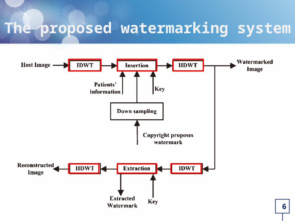
The proposed watermarking system
7
The proposed watermarking system
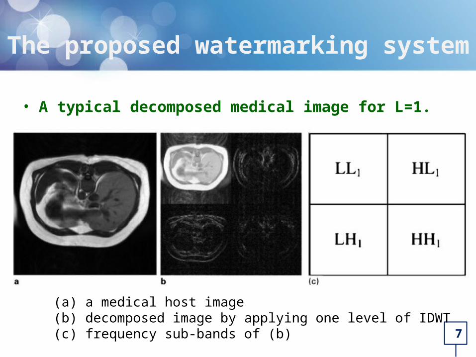
• A typical decomposed medical image for L=1.
(a) a medical host image(b) decomposed image by applying one level of IDWT(c) frequency sub-bands of (b)

8
The proposed watermarking system
Typical histogram of high frequency sub-bands of a medical grey scale image
• Step 1: Apply L levels of a 2D IDWT to the host image to obtain the decomposed one.

9
• Step 2: Find T1 and T2 on the high frequency sub-bands.
• Assume an M-bit watermark pattern, a horizontal line at M/2 are drawn to find the proper thresholds.
• The left side (beginning part) of the histogram, called T1.
• The right side (end part) of the histogram, called T2.
The proposed watermarking system

10
• Step 3: Create the zero-points ( Z1 and Z2 ) (a) Shift the left side of T1 to left by one unit to create Z1. (b) Shift the right side of T2 to right by one unit to create Z2
The proposed watermarking system

11
• Step 4: Create lower resolutions of the copyright protection binary logo watermark.
• Step 5: Encryption of the watermark, using a private key. - total size of the watermark is M+N bits.
(a) M bits copyright watermark. (b) N bits patient personal and examination data.
The proposed watermarking system

12
• Step 6: Insert the watermark (W)- Divide the watermark into two parts (W1 and W2).- Insert bit 0 and bit 1 of W1 at T1 and Z1 respectively.
- Insert bit 0 and bit 1 of W2 at T2 and Z2 respectively.
• Step 7: Apply L levels of 2D IIDWT to obtain the watermarked image in spatial domain.
221 where 1 N)/, ..., (M, iWCC iii
221 where 2 N)/, ..., (M, jWCC jjj
The proposed watermarking system

13
Insertion algorithm (1/4)
• EX: W1 = 0 1 0 1 1 0
T1 = -1
Z1 = -2
Shifted to left
0 2 -1 -3 -2
0 1 -2 -1 -3
-1 0 -1 0 -2
-2 -4 0 2 -1
-1 1 -1 -2 0
0 2 -1 -4 -3
0 1 -3 -1 -4
-1 0 -1 0 -3
-3 -5 0 2 -1
-1 1 -1 -3 0
If Ci < T1

14
Insertion algorithm (2/4)
0 2 -1 -4 -3
0 1 -3 -1 -4
-1 0 -1 0 -3
-3 -5 0 2 -1
-1 1 -1 -3 0
0 2 -1 -4 -3
0 1 -3 -2 -4
-1 0 -2 0 -3
-3 -5 0 2 -2
-1 1 -1 -3 0
Embedded W1
Used Ci = T1
• EX: W1 = 0 1 0 1 1 0
T1 = -1
Z1 = -2
Ci = Ci – W1i
-1=-1-0-2=-1-1

15
Insertion algorithm (3/4)
• EX: W2 = 1 1 0 1 0 1
T2 = 4
Z2 = 5
Shifted to right
If Cj > T2
3 4 6 4 5
3 3 4 4 5
7 7 4 3 6
6 5 5 3 4
3 3 6 3 3
3 4 7 4 6
3 3 4 4 6
8 8 4 3 7
7 6 6 3 4
3 3 7 3 3

16
Insertion algorithm (4/4)
Embedded W2
Used Cj = T2
Cj = Cj + W2j
4 = 4 + 0 5 = 4 + 1
• EX: W2 = 1 1 0 1 0 1
T2 = 4
Z2 = 5
3 4 7 4 6
3 3 4 4 6
8 8 4 3 7
7 6 6 3 4
3 3 7 3 3
3 5 7 5 6
3 3 4 5 6
8 8 4 3 7
7 6 6 3 5
3 3 7 3 3

17
0 2 -1 -4 -3
0 1 -3 -2 -4
-1 0 -2 0 -3
-3 -5 0 2 -2
-1 1 -1 -3 0
Extraction algorithm (1/2)
0 2 -1 -3 -2
0 1 -2 -1 -3
-1 0 -1 0 -2
-2 -4 0 2 -1
-1 1 -1 -2 0
-1 -4 -3
-2 -4
-1 0 -2 0 -3
-3 -5 0 2 -2
-1 1 -1 -3 0
Extracted W1 = 0 1 0 1 1 0
-1 → 0-2 → 1
• EX: T1 = -1 ; Z1 = -2
Shifted to right
If Ci < T1

18
3 5 7 5 6
3 3 4 5 6
8 8 4 3 7
7 6 6 3 5
3 3 7 3 3
Extraction algorithm (2/2)
3 4 6 4 5
3 3 4 4 5
7 7 4 3 6
6 5 5 3 4
3 3 6 3 3
3 5 7 5 6
3 3 4 5 6
8 8 4 3 7
7 6 6 3 5
3 3 7 3 3
Extracted W2 = 1 1 0 1 0 1
4 → 05 → 1
Shifted to left
If Cj > T2
• EX: T2 = 4 ; Z2 = 5

19
Experimental results (1/8)
(a) MR_liver_t1 (b) MR_ped_chest (c) MR_sag_head
• A slice of the medical images used for test:

20
Experimental results (2/8)
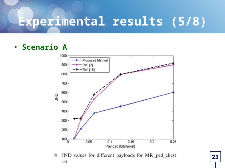
• Scenario AThe scenario A is dedicated to demonstrate the superiority of the method for the low payloads.

21
Experimental results (3/8)
• Scenario A

22
Experimental results (4/8)
• Scenario A
• 結構相似性影像質量指標 (mean structural similarity index measure, MSSIM)
• 正好察覺失真度 (just-noticeable distortion, JND)
23
Experimental results (5/8)
• Scenario A

24
Experimental results (6/8)
• Scenario BIn this scenario, superiority of the proposed method for embedding high amount of data in the host image is demonstrated.
(a) a medical host image(b) decomposed image by applying two level of IDWT(c) frequency sub-bands of (b)

25
Experimental results (7/8)
• Scenario B

26
Experimental results (8/8)
• Scenario B
(a)Host image
(b)Watermarked image (PSNR=49.54dB)

27
Conclusions
• Scalability and security.
• To solve underflow and overflow.
• The watermarked images have high quality.
• The watermark extraction process is blind and both watermark and host image is completely reconstruct without any loss.

Thanks for your attention !