reversible inverter air/water heatpump hydra · thermics energie s.r.l. via dell'olmo, 37/2...
TRANSCRIPT

THERMICS ENERGIE s.r.l.Via dell'Olmo, 37/2 – 33030 VARMO (UD) - ITALYPartita IVA C.F. e NR.ISCR.R.I.UD: 02700000306R.E.A.: 281298 Tel. +39 0432 823600 - Fax. +39 0432 [email protected] www.thermics-energie.it
1
Reversible inverter air/water heatpump
Hydra

THERMICS ENERGIE s.r.l.Via dell'Olmo, 37/2 – 33030 VARMO (UD) - ITALYPartita IVA C.F. e NR.ISCR.R.I.UD: 02700000306R.E.A.: 281298 Tel. +39 0432 823600 - Fax. +39 0432 [email protected] www.thermics-energie.it
2
DIMENSIONS Hydra 6

THERMICS ENERGIE s.r.l.Via dell'Olmo, 37/2 – 33030 VARMO (UD) - ITALYPartita IVA C.F. e NR.ISCR.R.I.UD: 02700000306R.E.A.: 281298 Tel. +39 0432 823600 - Fax. +39 0432 [email protected] www.thermics-energie.it
3
DIMENSIONS - Hydra 9 2T

THERMICS ENERGIE s.r.l.Via dell'Olmo, 37/2 – 33030 VARMO (UD) - ITALYPartita IVA C.F. e NR.ISCR.R.I.UD: 02700000306R.E.A.: 281298 Tel. +39 0432 823600 - Fax. +39 0432 [email protected] www.thermics-energie.it
4
DIMENSIONS - 4pipes version

THERMICS ENERGIE s.r.l.Via dell'Olmo, 37/2 – 33030 VARMO (UD) - ITALYPartita IVA C.F. e NR.ISCR.R.I.UD: 02700000306R.E.A.: 281298 Tel. +39 0432 823600 - Fax. +39 0432 [email protected] www.thermics-energie.it
5
DIMENSIONS - Hydra 12 and Hydra 14
1232

THERMICS ENERGIE s.r.l.Via dell'Olmo, 37/2 – 33030 VARMO (UD) - ITALYPartita IVA C.F. e NR.ISCR.R.I.UD: 02700000306R.E.A.: 281298 Tel. +39 0432 823600 - Fax. +39 0432 [email protected] www.thermics-energie.it
6
DIMENSIONS – internal unit - Hydra Split 150 DHW
Internal unit, part of Hydra Split 4T – 150 DHW.Composition of internal unit:
- DHW 150 liters tank, stainless steel made, stainless steel refrigerant de-superheater/condenser- 40 liters separation tank for heating-cooling circuit- Electronic circulation pump from plate HEX to 40 liters separation tank- Plate HEX refrigerant/water- Evco controller- Electrical switch-box- Touch-screen controller

THERMICS ENERGIE s.r.l.Via dell'Olmo, 37/2 – 33030 VARMO (UD) - ITALYPartita IVA C.F. e NR.ISCR.R.I.UD: 02700000306R.E.A.: 281298 Tel. +39 0432 823600 - Fax. +39 0432 [email protected] www.thermics-energie.it
7
REFRIGERANT CONNECTIONS- Hot gas inlet 3/8”- Hot gas outlet 3/8”- Evaporation gas suction 5/8”- Liquid injection inlet 3/8”
DHW connections- ¾” F connections
HEATING/COOLING CONNECTIONS- 1” F

THERMICS ENERGIE s.r.l.Via dell'Olmo, 37/2 – 33030 VARMO (UD) - ITALYPartita IVA C.F. e NR.ISCR.R.I.UD: 02700000306R.E.A.: 281298 Tel. +39 0432 823600 - Fax. +39 0432 [email protected] www.thermics-energie.it
8
TECHNICAL FEATURES
HYDRA 6 kW HYDRA 9 kWHYDRA 12
kWHYDRA 14
kW
Electrical supply V/HZ/Ph230/50/1+N
(Optional400/50/3+N)
230/50/1+N(Optional
400/50/3+N)
230/50/1+N(Optional
400/50/3+N)400/50/3+N
Compressor type Twin-rotary BLDC Twin-rotary BLDC Twin-rotary BLDC Twin-rotary BLDC
N° compressors Nr 1 1 1 1
Power modulation % 20÷100 20÷100 20÷100 20÷100
Refrigerant circuits Nr 1 1 1 1
Refrigerant quantity (R410a) Kg 1,8 3,0 4,2 5,2
HEX type Refrigerant/waterBrazed plate heat-
exchangerBrazed plate heat-
exchangerBrazed plate heat-
exchangerBrazed plate heat-
exchanger
HEX type Refrigerant/airFin&tube CU/ALheat-exchanger
Fin&tube CU/ALheat-exchanger
Fin&tube CU/ALheat-exchanger
Fin&tube CU/ALheat-exchanger
N° HEX Nr 1 1 1 1
Water flow (heating/coolingcircuit)
l/h 1200 1650 2200 2550
Max. temperature(heating/cooling circuit)
°C 53 53 53 53
Water connections(heating/cooling circuit)
1”1/4 (F) 1”1/4 (F) 1”1/4 (F) 1”1/4 (F)
Max water pressure kPa 550 550 550 550
Inertial tank capacity Litri optional optional optional optional
Expansion vessel Litri Not included Not included Not included Not included
Fan type Axial Axial Axial Axial
Air volume flow m3/h 0 – 3400 0 – 4000 0 – 5000 0 – 5800
Fan electrical power W 0 – 135 0 – 160 0 – 200 0 – 230
THERMICS ENERGIE s.r.l.Via dell'Olmo, 37/2 – 33030 VARMO (UD) - ITALYPartita IVA C.F. e NR.ISCR.R.I.UD: 02700000306R.E.A.: 281298 Tel. +39 0432 823600 - Fax. +39 0432 [email protected] www.thermics-energie.it
9
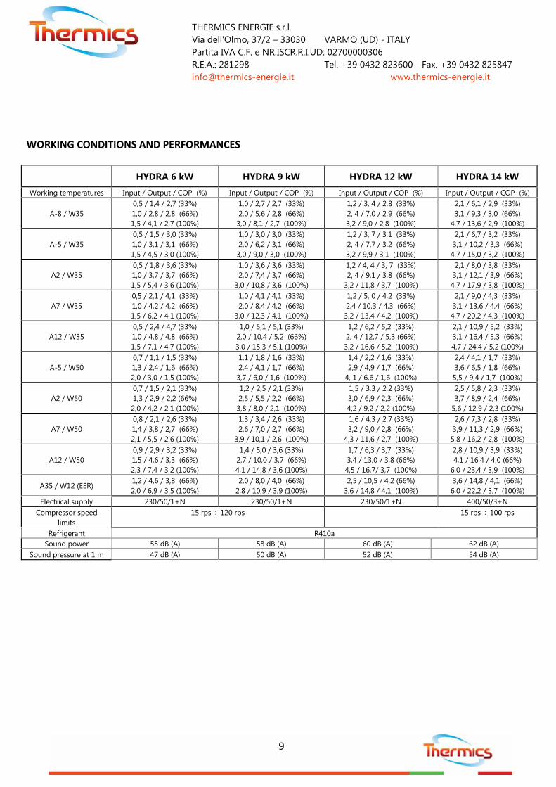
WORKING CONDITIONS AND PERFORMANCES
HYDRA 6 kW HYDRA 9 kW HYDRA 12 kW HYDRA 14 kW
Working temperatures Input / Output / COP (%) Input / Output / COP (%) Input / Output / COP (%) Input / Output / COP (%)
A-8 / W350,5 / 1,4 / 2,7 (33%)1,0 / 2,8 / 2,8 (66%)1,5 / 4,1 / 2,7 (100%)
1,0 / 2,7 / 2,7 (33%)2,0 / 5,6 / 2,8 (66%)3,0 / 8,1 / 2,7 (100%)
1,2 / 3, 4 / 2,8 (33%)2, 4 / 7,0 / 2,9 (66%)3,2 / 9,0 / 2,8 (100%)
2,1 / 6,1 / 2,9 (33%)3,1 / 9,3 / 3,0 (66%)
4,7 / 13,6 / 2,9 (100%)
A-5 / W350,5 / 1,5 / 3,0 (33%)1,0 / 3,1 / 3,1 (66%)1,5 / 4,5 / 3,0 (100%)
1,0 / 3,0 / 3,0 (33%)2,0 / 6,2 / 3,1 (66%)3,0 / 9,0 / 3,0 (100%)
1,2 / 3, 7 / 3,1 (33%)2, 4 / 7,7 / 3,2 (66%)3,2 / 9,9 / 3,1 (100%)
2,1 / 6,7 / 3,2 (33%)3,1 / 10,2 / 3,3 (66%)4,7 / 15,0 / 3,2 (100%)
A2 / W350,5 / 1,8 / 3,6 (33%)1,0 / 3,7 / 3,7 (66%)1,5 / 5,4 / 3,6 (100%)
1,0 / 3,6 / 3,6 (33%)2,0 / 7,4 / 3,7 (66%)
3,0 / 10,8 / 3,6 (100%)
1,2 / 4, 4 / 3, 7 (33%)2, 4 / 9,1 / 3,8 (66%)
3,2 / 11,8 / 3,7 (100%)
2,1 / 8,0 / 3,8 (33%)3,1 / 12,1 / 3,9 (66%)4,7 / 17,9 / 3,8 (100%)
A7 / W350,5 / 2,1 / 4,1 (33%)1,0 / 4,2 / 4,2 (66%)1,5 / 6,2 / 4,1 (100%)
1,0 / 4,1 / 4,1 (33%)2,0 / 8,4 / 4,2 (66%)
3,0 / 12,3 / 4,1 (100%)
1,2 / 5, 0 / 4,2 (33%)2,4 / 10,3 / 4,3 (66%)3,2 / 13,4 / 4,2 (100%)
2,1 / 9,0 / 4,3 (33%)3,1 / 13,6 / 4,4 (66%)4,7 / 20,2 / 4,3 (100%)
A12 / W350,5 / 2,4 / 4,7 (33%)1,0 / 4,8 / 4,8 (66%)1,5 / 7,1 / 4,7 (100%)
1,0 / 5,1 / 5,1 (33%)2,0 / 10,4 / 5,2 (66%)3,0 / 15,3 / 5,1 (100%)
1,2 / 6,2 / 5,2 (33%)2, 4 / 12,7 / 5,3 (66%)3,2 / 16,6 / 5,2 (100%)
2,1 / 10,9 / 5,2 (33%)3,1 / 16,4 / 5,3 (66%)4,7 / 24,4 / 5,2 (100%)
A-5 / W500,7 / 1,1 / 1,5 (33%)1,3 / 2,4 / 1,6 (66%)2,0 / 3,0 / 1,5 (100%)
1,1 / 1,8 / 1,6 (33%)2,4 / 4,1 / 1,7 (66%)3,7 / 6,0 / 1,6 (100%)
1,4 / 2,2 / 1,6 (33%)2,9 / 4,9 / 1,7 (66%)
4, 1 / 6,6 / 1,6 (100%)
2,4 / 4,1 / 1,7 (33%)3,6 / 6,5 / 1,8 (66%)5,5 / 9,4 / 1,7 (100%)
A2 / W500,7 / 1,5 / 2,1 (33%)1,3 / 2,9 / 2,2 (66%)2,0 / 4,2 / 2,1 (100%)
1,2 / 2,5 / 2,1 (33%)2,5 / 5,5 / 2,2 (66%)3,8 / 8,0 / 2,1 (100%)
1,5 / 3,3 / 2,2 (33%)3,0 / 6,9 / 2,3 (66%)4,2 / 9,2 / 2,2 (100%)
2,5 / 5,8 / 2,3 (33%)3,7 / 8,9 / 2,4 (66%)
5,6 / 12,9 / 2,3 (100%)
A7 / W500,8 / 2,1 / 2,6 (33%)1,4 / 3,8 / 2,7 (66%)2,1 / 5,5 / 2,6 (100%)
1,3 / 3,4 / 2,6 (33%)2,6 / 7,0 / 2,7 (66%)
3,9 / 10,1 / 2,6 (100%)
1,6 / 4,3 / 2,7 (33%)3,2 / 9,0 / 2,8 (66%)
4,3 / 11,6 / 2,7 (100%)
2,6 / 7,3 / 2,8 (33%)3,9 / 11,3 / 2,9 (66%)5,8 / 16,2 / 2,8 (100%)
A12 / W500,9 / 2,9 / 3,2 (33%)1,5 / 4,6 / 3,3 (66%)2,3 / 7,4 / 3,2 (100%)
1,4 / 5,0 / 3,6 (33%)2,7 / 10,0 / 3,7 (66%)4,1 / 14,8 / 3,6 (100%)
1,7 / 6,3 / 3,7 (33%)3,4 / 13,0 / 3,8 (66%)4,5 / 16,7/ 3,7 (100%)
2,8 / 10,9 / 3,9 (33%)4,1 / 16,4 / 4,0 (66%)
6,0 / 23,4 / 3,9 (100%)
A35 / W12 (EER)1,2 / 4,6 / 3,8 (66%)2,0 / 6,9 / 3,5 (100%)
2,0 / 8,0 / 4,0 (66%)2,8 / 10,9 / 3,9 (100%)
2,5 / 10,5 / 4,2 (66%)3,6 / 14,8 / 4,1 (100%)
3,6 / 14,8 / 4,1 (66%)6,0 / 22,2 / 3,7 (100%)
Electrical supply 230/50/1+N 230/50/1+N 230/50/1+N 400/50/3+NCompressor speed
limits15 rps ÷ 120 rps 15 rps ÷ 100 rps
Refrigerant R410aSound power 55 dB (A) 58 dB (A) 60 dB (A) 62 dB (A)
Sound pressure at 1 m 47 dB (A) 50 dB (A) 52 dB (A) 54 dB (A)

THERMICS ENERGIE s.r.l.Via dell'Olmo, 37/2 – 33030 VARMO (UD) - ITALYPartita IVA C.F. e NR.ISCR.R.I.UD: 02700000306R.E.A.: 281298 Tel. +39 0432 823600 - Fax. +39 0432 [email protected] www.thermics-energie.it
10
INSTALLATION
Hydra external units have been engineered to allow external installation. External units can withstand wind,snow and rain weather conditions.
Hydraulic installation- Every separate circuit must be provided with proper-dimensioned expansion vessel, safety valve, Y-
filters and draining/filling connections, with pressure measurement equipment included- Maximum working pressure of heatpump is given in 5.5 bar- Take maximum care about system heating/cooling plant, project mass flow and project pressure drops
must be considered- If plant project-flow is higher than heat-pump nominal flow provide a hydraulic separation by means of
a separation buffer tank or by means of a plate heat-exchanger.- Provide auxiliary hydraulic connections on each circuit to allow maintenance operations such as cleaning
HEX with external pump

THERMICS ENERGIE s.r.l.Via dell'Olmo, 37/2 – 33030 VARMO (UD) - ITALYPartita IVA C.F. e NR.ISCR.R.I.UD: 02700000306R.E.A.: 281298 Tel. +39 0432 823600 - Fax. +39 0432 [email protected] www.thermics-energie.it
11
Heatpump positioning
Please take maximum care to select the proper installation place before positioning the external unit outdoor.
Select the installation place trying to maximize the following aspects:- Most protected place, the hotter the installation place the better the winter performance will be- Well ventilate place- Indoor installation is not allowed except if pre-engineered and/or allowed by Thermics and/or by official
commissioning teamo Indoor installation can be evaluated with proper fan dimensioning, proper air-ducts for inlet and
outlet
Min. 150 mm Min. 500 mm
Min. 150 mm
Min. 1500 mm
Min. 500 mm
Min. 150 mm

THERMICS ENERGIE s.r.l.Via dell'Olmo, 37/2 – 33030 VARMO (UD) - ITALYPartita IVA C.F. e NR.ISCR.R.I.UD: 02700000306R.E.A.: 281298 Tel. +39 0432 823600 - Fax. +39 0432 [email protected] www.thermics-energie.it
12
Noise and vibrations
Positioning recommendations:- Avoid external unit installation in proximity of sleeping-room’s wall and/or window- Take care about neighbour position
Vibration reduction:- Please provide installation of anti-vibration pads- Try to avoid direct contact between internal unit and floor- Try to avoid direct mounting of heatpump units on the wall
Heatpump over-positioning
In case of possible installation of external unit on:- Roof level- Metal-roof- Façade
Take particular care to the following:- Static load calculations- Antiseismic calculations- Vibrations transmission on supporting structures- Proper draining of condensate water

THERMICS ENERGIE s.r.l.Via dell'Olmo, 37/2 – 33030 VARMO (UD) - ITALYPartita IVA C.F. e NR.ISCR.R.I.UD: 02700000306R.E.A.: 281298 Tel. +39 0432 823600 - Fax. +39 0432 [email protected] www.thermics-energie.it
13
Condensate drainingAir-water heatpumps produce large amounts of condensate water during their standard functioning. Takeparticular care to the draining system and to external unit installation place.
Avoid cold condensate water to become ice on the road or on the pedestrian transit areas.
The best drainage connections to waste water grid can be done using a properly dimensioned syphonconnection.
Keep all possible antifreeze actions to avoid condensate water to ice during the discharge pattern to thewastewater grid.
Provide the right installation height to allow a good natural flow down of the condesate water.

THERMICS ENERGIE s.r.l.Via dell'Olmo, 37/2 – 33030 VARMO (UD) - ITALYPartita IVA C.F. e NR.ISCR.R.I.UD: 02700000306R.E.A.: 281298 Tel. +39 0432 823600 - Fax. +39 0432 [email protected] www.thermics-energie.it
14
EXTERNAL UNIT

THERMICS ENERGIE s.r.l.Via dell'Olmo, 37/2 – 33030 VARMO (UD) - ITALYPartita IVA C.F. e NR.ISCR.R.I.UD: 02700000306R.E.A.: 281298 Tel. +39 0432 823600 - Fax. +39 0432 [email protected] www.thermics-energie.it
15
INTERNAL UNIT (only for HYDRA SPLIT – 2/4T)
REFRIGERANT CONNECTIONS- Mandata gas desurriscaldatore 3/8”- Ritorno gas desurriscaldatore 3/8”- Mandata gas (caldo freddo)5/8”- Ritorno liquido (caldo-freddo) 3/8”
HYDRAULIC CONNECTIONS- High temperature circuit HT ¾”- Heating/cooling circuit 1”
INTERNAL UNIT WEIGHT 45 Kg

THERMICS ENERGIE s.r.l.Via dell'Olmo, 37/2 – 33030 VARMO (UD) - ITALYPartita IVA C.F. e NR.ISCR.R.I.UD: 02700000306R.E.A.: 281298 Tel. +39 0432 823600 - Fax. +39 0432 [email protected] www.thermics-energie.it
16
ELECTRICAL CONNECTIONS
As represented in the picture below, installer must take care about- main electrical supply- touch-screen monitor connection
Auxiliary input-output are available as hard-contacts:- ALARM contact closes when Error happens- 4 free contacts normally open are available to manage heatpump remotely
o Power: turning on/off the unito Summer: activating summer mode, the heat-pump goes in cooling modeo Set2: when closed the heatpump targets the second setpoint seto Economy: low consumption and low-noise mode
- Sensors: NTC sensors are usually provided to monitoro Remote DHW tank (NTC-BOILER). Take care to position it in a medium-upper parto Remote buffer tank (NTC-plant). This sensor is usually internally connected to the plate HEX
(condenser, evaporator). It can be connected to a remote buffer tank during commissioning.- Physical power relay.
o Able to drive 1500 W electrical heater (230V) or auxiliary charging pump
Display24V O 24V O
+ O -- O
Electrical supply230V/50Hz
TE O
Neutral N O
Line L1 O
FUSE (1A) L O
ALARM NO9 O C9 O
POWER ID1 O +12V O
SUMMER ID2 O +12V O
SET 2 ID3 O +12V O
ECONOMY ID4 O +12V O
NTC - Boiler AI7 O GND O
NTC - IN Imp. AI5 O GND OELECTRIC HEATER(max1,5kW) R1 O N O

THERMICS ENERGIE s.r.l.Via dell'Olmo, 37/2 – 33030 VARMO (UD) - ITALYPartita IVA C.F. e NR.ISCR.R.I.UD: 02700000306R.E.A.: 281298 Tel. +39 0432 823600 - Fax. +39 0432 [email protected] www.thermics-energie.it
17
LED DISPLAY (installed on external unit)
Evco controller is provided by a led controller with 2lines and surrounding icons.It is possible to check and/or edit functioning valuesand parameters using the 6 button keyboard
Symbols
Winter heating mode: heatpump is set in heating mode to get hot water.
Summer cooling mode.
Compressor: when blinking a coutdown is in process, when steady on the compressors is running.
Circulation pump: when blinking the speed request is below 50%, when steady the water mas flow ismore than 50% of maximum.
Fan: when blinking speed request is below 60% of maximum speed, when steady speed request isalmost high.
Defrosting: when blinking ice is creating on evaporator, when steady defrosting is in action.
Hot gas bypass: used for a light defrost and/or to equalize refrigerant pressures.
Waiting: if on the system is in OFF mode.
Alarm: when active and error/alarm occurred.
4-way valve: when steady-on the system is working in summer cooling mode.
Set2: when on, a second SET-group is active.
Economy: Economy mode is on.
Compressor limitation: software is decreasing compressor power due to a higher limitation/protectionlogic active.
Defrosting mode: shows defrosting made with cycle reversal.

THERMICS ENERGIE s.r.l.Via dell'Olmo, 37/2 – 33030 VARMO (UD) - ITALYPartita IVA C.F. e NR.ISCR.R.I.UD: 02700000306R.E.A.: 281298 Tel. +39 0432 823600 - Fax. +39 0432 [email protected] www.thermics-energie.it
18
High temperature-pump: high-temperature circuit is active. If blinking the pump speed is lower than50%, when steady the speed is higher than 50%.
Keyboard
Escape (ESC)
Left button (LEFT): go back to previous view
Increase button (UP): increase value or scroll up a menu
Decrease button (DOWN): decrease value or scroll down a menu
Right button (RIGHT): go to following view
Confirmation key (ENTER): activates edit mode and/or confirms editing.
STARTING SCREEN
Starting screen shows heatpump status and water inlettemperature.

THERMICS ENERGIE s.r.l.Via dell'Olmo, 37/2 – 33030 VARMO (UD) - ITALYPartita IVA C.F. e NR.ISCR.R.I.UD: 02700000306R.E.A.: 281298 Tel. +39 0432 823600 - Fax. +39 0432 [email protected] www.thermics-energie.it
19
SECOND SCREEN
Going 1 step on the right, Menu page is showed. Inside Menu pageit’s possible to surf the sub-menu using UP and DOWN buttons. Enterbutton can be used to enter inside sub-menus. Inside sub-menus it ispossible to surf on the right and left.
Lev.0 Lev.1 Lev.2 Settings Default UnitsSet1 ESt t 25 Water temperature set with outside temperature equal or lower
than 25°C. 10,0 °C
t 35Water temperature set with outside temperature equal or higherthan 35°C.: for intermediate temperatures setpoint will beproportionally calculated.
8,0 °C
IStE
Summer hysteresis: temperature difference to be summed to SET.This is highest temperature limit. Higher water temperatures willforce compressor to maximum, lower value than SET-HYS will causecompressor shutting down.
1,5 °C
InV t 10 Winter water set with external temperature higher than 10°C. 41,0 °C
t -5Winter water set with external temperature lower than -5°C. Forintermediate temperatures setpoint will be proportionallycalculated
44,0 °C
IStI
Winter hysteresis: temperature difference to be summed to SET.This is highest temperature limit. Higher water temperatures willforce compressor to off, lower value than SET-HYS will causecompressor running at maximum speed.
2,0 °C
ACS ACS1 Drinkable hot water set 10,0 °C
IStS
DHW hysteresis: temperature difference to be summed to SET. Thisis highest temperature limit. Higher water temperatures will forcecompressor to off, lower value than SET-HYS will cause compressorrunning at maximum allowed speed.
1,5 °C
Set2 ESt t 25 Water temperature set with outside temperature equal or lowerthan 25°C. 8,0 °C
t 35Water temperature set with outside temperature equal or higherthan 35°C.: for intermediate temperatures setpoint will beproportionally calculated.
7,0 °C
InV t 10 Winter water set with external temperature higher than 10°C. 43,0 °C
t -5Winter water set with external temperature lower than -5°C. Forintermediate temperatures setpoint will be proportionallycalculated
45,0 °C
ACS ACS2 Drinkable hot water set 10,0 °CtEMP Cond Condensation temperature °C
EvAP Evaporation temperature °CbAtt Air-gas HEX temperature °CAriA Outdoor air temperature °CIn P Plate HEX inlet temperature °C

THERMICS ENERGIE s.r.l.Via dell'Olmo, 37/2 – 33030 VARMO (UD) - ITALYPartita IVA C.F. e NR.ISCR.R.I.UD: 02700000306R.E.A.: 281298 Tel. +39 0432 823600 - Fax. +39 0432 [email protected] www.thermics-energie.it
20
OutP Plate HEX outlet temperature °CScAr Hot gas compressor outlet °CSott Temperature difference between condensation and liquid exit
temperature.°C
Surr Temperature difference between evaporation and suctiontemperature
°C
ACS DHW temperature °CIMPO MAXE Maximum compressor power in summer mode 80 %
MAXI Maximum compressor power in winter mode 100 %FAnE Maximum fan speed in summer mode 60 %FAnI Maximum fan speed in winter mode 80 %PuMH Maximum heating pump-speed 100,0PuML Minimum heating pump-speed 40,0P On Heating plant pump active in stanby (1=yes) 1GELO Limit temperature for ice protection 2,0 °CtSGC Count-down before releasing hot-gas defrosting 900 stSIn Count-down before releasing reversal defrosting 1500 snSFA Maximum hot-gas defrosting failed attempts 1OnAG Alow system startup with frost alarm nOSEtG Frost-protection water set 10.0 °CtriF Reference sensor tOutAttE Maximum power in Economy mode 80 %ACS DHW preparation mode acitvation (if 4pipes version) OnPACS DHW priority SISIM2 Plant sensor positioning (UE= externa unit / remo = remote buffer
tank) UE
MAXA Maximum compressor power during DHW preparation 50 %ALL ALHP High pressure alarm (Hard error)
ALLP Low pressure alarm (this alarm can be temporary)ALFL Flow-switch alarm: bad water circulationALbt Low water temperature during cooling modeAGAS Refrigerant alarm: refrigerant missingALSt Temperature sensor alarmALSI Compressor inverter driver alarmALVE Fan alarm
MAnu SISt Sistem: when selected REMOTO (remo) command arrives fromdigital inputs; if set to MANUAL (manu) it is possible to activate itfrom following parameters
manu
StAt Status: if set to ON, with MANUAL mode activated the heat-pumpwill start. OFF
StAG Season: manually set season and functioning mode. InV modemeans heating. InV
ForZ ForS Forces defrosting with cycle reversal. OFFRitS Monitoring time countdown before hot-gas defrosting. 900 sLonS Maximum time for hot gas defrosting 220 snSFA Maximum hot gas defrosting attempts 1tbon Bonus for quick defrost 60 s

THERMICS ENERGIE s.r.l.Via dell'Olmo, 37/2 – 33030 VARMO (UD) - ITALYPartita IVA C.F. e NR.ISCR.R.I.UD: 02700000306R.E.A.: 281298 Tel. +39 0432 823600 - Fax. +39 0432 [email protected] www.thermics-energie.it
21
tArG Target ON: time between 2 defrostings 0 sSonb Time On during ice creation 0 s
ProG ProG Select different programming ways (SEtt=weekly; Gior=dayly) OFFSet2 Activates second setpoint (SET 2) according time programme: t_On tOFFEcon Activates Economy mode according time programme: t_On tOFF
FEri On 1 Time-on for working-days - 1st time area 6.30OFF1 Time-off for working-days - 1st time area 19.15On 2 Time-on for working-days - 2nd time area 7.00OFF2 Time-off for working-days - 2nd time area 7.00On 3 Time-on for working-days - 3rd time area 7.00OFF3 Time-off for working-days - 3rd time area 7.00OnS2 Activation time for SET2 during working days 7.00OFS2 De-activation time for SET2 during working days 7.00OnEc Activation time for ECONOMY during working days 7.00OFEc De-activation time for ECONOMY during working days 7.00
FESt On 4 Time-on for holidays - 1st time area 7.00OFF4 Time-off for holidays - 1st time area 7.00On 5 Time-on for holidays - 2nd time area 7.00OFF5 Time-off for holidays - 2nd time area 7.00On 6 Time-on for holidays - 3rd time area 7.00OFF6 Time-off for holidays - 3rd time area 7.00OnS2 Activation time for SET2 during holidays 7.00OFS2 De-activation time for SET2 during holidays 7.00OnEc Activation time for ECONOMY during holidays 7.00OFEc De-activation time for ECONOMY during holidays 7.00
Gior LuOn Daily activation time - Monday 5.00LuOF Daily de-activation time - Monday 19.15MAOn Daily activation time - Tuesday 7.00MAOF Daily de-activation time - Tuesday 19.15MEOn Daily activation time - Wednesday 7.00MEOF Daily de-activation time - Wednesday 19.15GiOn Daily activation time - Thursday 7.00GiOF Daily de-activation time - Thursday 19.15VEOn Daily activation time - Friday 7.00VEOF Daily de-activation time - Friday 19.15SAOn Daily activation time - Saturday 7.00SAOF Daily de-activation time - Saturday 7.00doOn Daily activation time - Sunday 7.00doOF Daily de-activation time - Sunday 7.00

THERMICS ENERGIE s.r.l.Via dell'Olmo, 37/2 – 33030 VARMO (UD) - ITALYPartita IVA C.F. e NR.ISCR.R.I.UD: 02700000306R.E.A.: 281298 Tel. +39 0432 823600 - Fax. +39 0432 [email protected] www.thermics-energie.it
22
THIRD SCREEN-PAGE
Pushig right button from 2nd screen page you get 3rd page withcompressor power percentage showed.

THERMICS ENERGIE s.r.l.Via dell'Olmo, 37/2 – 33030 VARMO (UD) - ITALYPartita IVA C.F. e NR.ISCR.R.I.UD: 02700000306R.E.A.: 281298 Tel. +39 0432 823600 - Fax. +39 0432 [email protected] www.thermics-energie.it
23
4TH SCREEN PAGE
Con il tasto RIGHT dalla terza schermata si può visualizzare la potenza reale richiesta alventilatore EC espressa in percentuale.
5TH SCREEN PAGE
Software version
6TH SCREEN PAGE
Actual time and date, followed by year.
7TH SCREEN PAGE
Week day calculated according date
8TH SCREEN PAGE
Code showing activated time programme
9TH SCREEN PAGE
Heating/cooling plant pump speed percentage.
10TH SCREEN PAGE
High temperature pump speed percentage.