rev01 ln-25™ pro - lincoln...
TRANSCRIPT

IM2071 10/2017 REV01
LN-25™ PRO
OPERATOR’S MANUAL
ENGLISH
THE LINCOLN ELECTRIC COMPANY 22801 St. Clair Ave., Cleveland Ohio 44117-1199 USA
www.lincolnelectric.eu
English English I
THE LINCOLN ELECTRIC COMPANY
EC DECLARATION OF CONFORMITY Manufacturer and technical documentation holder:
The Lincoln Electric Company
Address:
22801 St. Clair Ave. Cleveland Ohio 44117-1199 USA
EC Company:
Lincoln Electric Europe S.L.
Address:
c/o Balmes, 89 - 80 2a 08008 Barcelona SPAIN
Hereby declare that welding equipment:
LN-25 PRO & LN-25 PRO Dual, Wire Feeders
Product Numbers:
K2613 & K2614 (Product numbers may also contain prefixes and suffixes)
Is in conformity with Council Directives and amendments:
Electromagnetic Compatibility (EMC) Directive 2014/30/EU
Low Voltage Directive 2014/35/EU
Standards: EN 60974-5: 2013, Arc Welding Equipment – Part 5: Wire Feeders, EN 60974-10: 2007 Arc Welding Equipment – Part 10: Electromagnetic compatibility (EMC) requirements;
CE marking affixed in 08
Samir Farah, Manufacturer Dario Gatti, European Community Representative
Compliance Engineering Manager European Engineering Director Machines
17 May 2016 19 May 2016 MCD143e

English English II
12/05
THANKS! For having chosen the QUALITY of the Lincoln Electric products. Please Examine Package and Equipment for Damage. Claims for material damaged in shipment must be notified
immediately to the dealer. For future reference record in the table below your equipment identification information. Model Name, Code &
Serial Number can be found on the machine rating plate.
Model Name:
………………...…………………………….…………………………………………………………………………………………..Code & Serial number:
………………….……………………………………………….. …………………………………………………….……………..
Date & Where Purchased:
…………………………………………………………………... ……………………….…………………………………………..
ENGLISH INDEX Technical specifications ...................................................................................................................................................... 1 Electromagnetic Compatibility (EMC) ................................................................................................................................. 2 Safety .................................................................................................................................................................................. 3 Installation and Operator Instructions ................................................................................................................................. 4 WEEE ................................................................................................................................................................................ 18 Spare Parts ....................................................................................................................................................................... 18 Authorized Service Shops Location .................................................................................................................................. 18 Electrical Schematic .......................................................................................................................................................... 19 Suggested Accessories ..................................................................................................................................................... 20

English English 1
Technical specifications LN-25™ PRO (K2613-5, K2613-7) (CODE NUMBER: 11746, 11747).
INPUT VOLTAGE AND CURRENT INPUT VOLTAGE ± 10% INPUT AMPERES
15-110 VDC
4A
RATED OUTPUT @ 104°F (40°C) DUTY CYCLE INPUT AMPERES
60% RATING 450
GEARING - WIRE FEED SPEED RANGE-WIRE SIZE
GEARING GMAW FCAW
WFS RANGE WIRE SIZES WFS RANGE WIRE SIZES
EXTRA TORQUE K2613-7 50 – 400 IPM
(1.3 – 10.1M/MIN).023 – 1/16"
(0.6 – 1.6MM) 50 – 400 IPM
(1.3 – 10.1M/MIN) .030 - 3/32”
(0.8 – 2.4MM)
STANDARD SPEED K2613-5
50 – 700 IPM (1.3 – 17.7M/MIN)
.023 – 1/16" (0.6 – 1.6MM)
50 – 700 IPM (1.3 – 17.7M/MIN)
.030 - 5/64 (0.8 - 2.0MM)
PHYSICAL DIMENSIONS HEIGHT WIDTH DEPTH WEIGHT
14.8 INCHES (376 MM)
HANDLE FOLDED DOWN
8.7 INCHES ( 221 MM)
23.2 INCHES (589 MM)
38 LBS (17 KG)
TEMPERATURE RANGE
OPERATION: STORAGE: -40°F TO 104°F (-40°C TO 40°C) -40°F TO 122°F (-40°C TO 50°C)
Thermal tests have been performed at ambient temperature. The duty cycle (duty factor) at 40°C has been determined by simulation. Duty cycle is based upon the amount of welding performed in a 10 minute period.
IP23 IEC 60974-5

English English 2
Electromagnetic Compatibility (EMC) 01/11
This machine has been designed in accordance with all relevant directives and standards. However, it may still generate electromagnetic disturbances that can affect other systems like telecommunications (telephone, radio, and television) or other safety systems. These disturbances can cause safety problems in the affected systems. Read and understand this section to eliminate or reduce the amount of electromagnetic disturbance generated by this machine.
This machine has been designed to operate in an industrial area. To operate in a domestic area it is necessary to observe particular precautions to eliminate possible electromagnetic disturbances. The operator must install and operate this equipment as described in this manual. If any electromagnetic disturbances are detected the operator must put in place corrective actions to eliminate these disturbances
with, if necessary, assistance from Lincoln Electric. Before installing the machine, the operator must check the work area for any devices that may malfunction because of electromagnetic disturbances. Consider the following. Input and output cables, control cables, and telephone cables that are in or adjacent to the work area and the
machine. Radio and/or television transmitters and receivers. Computers or computer controlled equipment. Safety and control equipment for industrial processes. Equipment for calibration and measurement. Personal medical devices like pacemakers and hearing aids. Check the electromagnetic immunity for equipment operating in or near the work area. The operator must be sure
that all equipment in the area is compatible. This may require additional protection measures. The dimensions of the work area to consider will depend on the construction of the area and other activities that are
taking place. Consider the following guidelines to reduce electromagnetic emissions from the machine. Connect the machine to the input supply according to this manual. If disturbances occur if may be necessary to take
additional precautions such as filtering the input supply. The output cables should be kept as short as possible and should be positioned together. If possible connect the
work piece to ground in order to reduce the electromagnetic emissions. The operator must check that connecting the work piece to ground does not cause problems or unsafe operating conditions for personnel and equipment.
Shielding of cables in the work area can reduce electromagnetic emissions. This may be necessary for special applications.
WARNING EMC classification of this product is class A in accordance with electromagnetic compatibility standard EN 60974-10 and therefore the product is designed to be used in an industrial environment only.
WARNING The Class A equipment is not intended for use in residential locations where the electrical power is provided by the public low-voltage supply system. There can be potential difficulties in ensuring electromagnetic compatibility in those locations, due to conducted as well as radio-frequency disturbances.

English English 3
Safety 11/04
WARNING This equipment must be used by qualified personnel. Be sure that all installation, operation, maintenance and repair procedures are performed only by qualified person. Read and understand this manual before operating this equipment. Failure to follow the instructions in this manual could cause serious personal injury, loss of life, or damage to this equipment. Read and understand the following explanations of the warning symbols. Lincoln Electric is not responsible for damages caused by improper installation, improper care or abnormal operation.
WARNING: This symbol indicates that instructions must be followed to avoid serious personal injury, loss of life, or damage to this equipment. Protect yourself and others from possible serious injury or death.
READ AND UNDERSTAND INSTRUCTIONS: Read and understand this manual before operating this equipment. Arc welding can be hazardous. Failure to follow the instructions in this manual could cause serious personal injury, loss of life, or damage to this equipment.
ELECTRIC SHOCK CAN KILL: Welding equipment generates high voltages. Do not touch the electrode, work clamp, or connected work pieces when this equipment is on. Insulate yourself from the electrode, work clamp, and connected work pieces.
ELECTRICALLY POWERED EQUIPMENT: Turn off input power using the disconnect switch at the fuse box before working on this equipment. Ground this equipment in accordance with local electrical regulations.
ELECTRICALLY POWERED EQUIPMENT: Regularly inspect the input, electrode, and work clamp cables. If any insulation damage exists replace the cable immediately. Do not place the electrode holder directly on the welding table or any other surface in contact with the work clamp to avoid the risk of accidental arc ignition.
ELECTRIC AND MAGNETIC FIELDS MAY BE DANGEROUS: Electric current flowing through any conductor creates electric and magnetic fields (EMF). EMF fields may interfere with some pacemakers, and welders having a pacemaker shall consult their physician before operating this equipment.
CE COMPLIANCE: This equipment complies with the European Community Directives.
FUMES AND GASES CAN BE DANGEROUS: Welding may produce fumes and gases hazardous to health. Avoid breathing these fumes and gases. To avoid these dangers the operator must use enough ventilation or exhaust to keep fumes and gases away from the breathing zone.
ARC RAYS CAN BURN: Use a shield with the proper filter and cover plates to protect your eyes from sparks and the rays of the arc when welding or observing. Use suitable clothing made from durable flame-resistant material to protect you skin and that of your helpers. Protect other nearby personnel with suitable, non-flammable screening and warn them not to watch the arc nor expose themselves to the arc.
WELDING SPARKS CAN CAUSE FIRE OR EXPLOSION: Remove fire hazards from the welding area and have a fire extinguisher readily available. Welding sparks and hot materials from the welding process can easily go through small cracks and openings to adjacent areas. Do not weld on any tanks, drums, containers, or material until the proper steps have been taken to insure that no flammable or toxic vapors will be present. Never operate this equipment when flammable gases, vapors or liquid combustibles are present.
WELDED MATERIALS CAN BURN: Welding generates a large amount of heat. Hot surfaces and materials in work area can cause serious burns. Use gloves and pliers when touching or moving materials in the work area.
SAFETY MARK: This equipment is suitable for supplying power for welding operations carried out in an environment with increased hazard of electric shock.
English English 4
CYLINDER MAY EXPLODE IF DAMAGED: Use only compressed gas cylinders containing the correct shielding gas for the process used and properly operating regulators designed for the gas and pressure used. Always keep cylinders in an upright position securely chained to a fixed support. Do not move or transport gas cylinders with the protection cap removed. Do not allow the electrode, electrode holder, work clamp or any other electrically live part to touch a gas cylinder. Gas cylinders must be located away from areas where they may be subjected to physical damage or the welding process including sparks and heat sources.
NOISE APPEARES DURING WELDING CAN BE HARMFUL: Welding arc can cause noise with high level of 85dB for 8-hour week day. Welders operating welding machines are obligated to wear the proper ear protectors /appendix No. 2 for the Decree of the Secretary of Labor and Social Policy from 17.06 1998 – Dz.U. No. 79 pos. 513/. According to the Decree the Secretary of Health and Social Welfare from 09.07.1996 /Dz.U. No. 68 pos. 194/, employers are obligated to carry examinations and measurements of health harmful factors. MOVING PARTS ARE DANGEROUS: There are moving mechanical parts in this machine, which can cause serious injury. Keep your hands, body and clothing away from those parts during machine starting, operating and servicing.
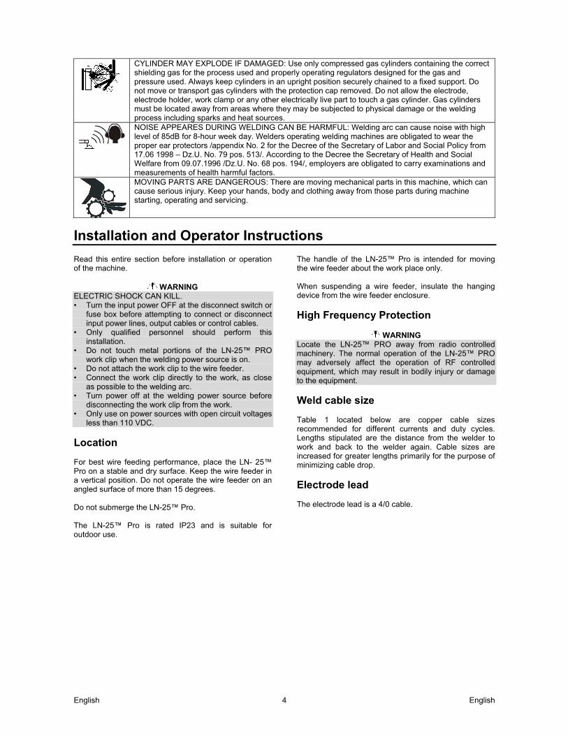
Installation and Operator Instructions Read this entire section before installation or operation of the machine.
WARNING ELECTRIC SHOCK CAN KILL. • Turn the input power OFF at the disconnect switch or
fuse box before attempting to connect or disconnect input power lines, output cables or control cables.
• Only qualified personnel should perform this installation.
• Do not touch metal portions of the LN-25™ PRO work clip when the welding power source is on.
• Do not attach the work clip to the wire feeder. • Connect the work clip directly to the work, as close
as possible to the welding arc. • Turn power off at the welding power source before
disconnecting the work clip from the work. • Only use on power sources with open circuit voltages
less than 110 VDC.
Location For best wire feeding performance, place the LN- 25™ Pro on a stable and dry surface. Keep the wire feeder in a vertical position. Do not operate the wire feeder on an angled surface of more than 15 degrees. Do not submerge the LN-25™ Pro. The LN-25™ Pro is rated IP23 and is suitable for outdoor use.
The handle of the LN-25™ Pro is intended for moving the wire feeder about the work place only. When suspending a wire feeder, insulate the hanging device from the wire feeder enclosure.
High Frequency Protection
WARNING Locate the LN-25™ PRO away from radio controlled machinery. The normal operation of the LN-25™ PRO may adversely affect the operation of RF controlled equipment, which may result in bodily injury or damage to the equipment.
Weld cable size Table 1 located below are copper cable sizes recommended for different currents and duty cycles. Lengths stipulated are the distance from the welder to work and back to the welder again. Cable sizes are increased for greater lengths primarily for the purpose of minimizing cable drop.
Electrode lead The electrode lead is a 4/0 cable.

English English 5
RECOMMENDED CABLE SIZES (RUBBER COVERED COPPER - RATED 167°F OR 75°C)**
AMPERES PERCENT
DUTY CYCLE
CABLE SIZES FOR COMBINED LENGTHS OF ELECTRODE AND WORK CABLES
0 to 50 Ft. (0 to15m)
50 to 100 Ft. (15 to 30m)
100 to 150 Ft. (30 to 46m)
150 to 200 Ft. (46 to 61m)
200 to 250 Ft. (61 to 76m)
200 200 225 225 250
60 100 20
40 & 30 30
2 2
4 or 5 3 3
2 2 3 3 3
2 2 2 2 2
1 1 1 1 1
1/0 1/0 1/0 1/0 1/0
250 250 250 300
40 60 100 60
2 1 1 1
2 1 1 1
1 1 1 1
1 1 1
1/0
1/0 1/0 1/0 2/0
325 350 400 400 500
100 60 60 100 60
2/0 1/0 2/0 3/0 2/0
2/0 1/0 2/0 3/0 2/0
2/0 2/0 2/0 3/0 3/0
2/0 2/0 3/0 3/0 3/0
3/0 3/0 4/0 4/0 4/0
** Tabled values are for operation at ambient temperatures of 104°F(40°C) and below. Applications above 104°F(40°C) may require cables larger than recommended, or cables rated higher than 167°F(75°C).
Table 1
Shielding gas connection
WARNING CYLINDER MAY EXPLODE IF DAMAGED. • Keep cylinder upright and chained to support. • Keep cylinder away from areas where it may be
damaged. • Never lift welder with cylinder attached. • Never allow welding electrode to touch cylinder. • Keep cylinder away from welding or other live
electrical circuits. • BUILD UP OF SHIELDING GAS MAY HARM
HEALTH OR KILL. • Shut off shielding gas supply when not in use. • See American National Standard z-49.1, "Safety in
Welding and Cutting” Published by the American Welding Society.
Maximum inlet pressure is 100 psi. (6.9 bar.) Install the shielding gas supply as follows: 1. Secure the cylinder to prevent it from falling. 2. Remove the cylinder cap. Inspect the cylinder valves
and regulator for damaged threads, dirt, dust, oil or grease. Remove dust and dirt with a clean cloth. DO NOT ATTACH THE REGULATOR IF OIL, GREASE OR DAMAGE IS PRESENT! Inform your gas supplier of this condition. Oil or grease in the presence of high pressure oxygen is explosive.
3. Stand to one side away from the outlet and open the cylinder valve for an instant. This blows away any dust or dirt which may have accumulated in the valve outlet.
4. Attach the flow regulator to the cylinder valve and tighten the union nut(s) securely with a wrench. Note: if connecting to 100% CO2 cylinder, insert regulator adapter between regulator and cylinder valve. If adapter is equipped with a plastic washer, be sure it is seated for connection to the CO2 cylinder.
5. Attach one end of the inlet hose to the outlet fitting of the flow regulator. Attach the other end to the welding system shielding gas inlet. Tighten the union nuts with a wrench.
6. Before opening the cylinder valve, turn the regulator adjusting knob counterclockwise until the adjusting spring pressure is released.
7. Standing to one side, open the cylinder valve slowly a fraction of a turn. When the cylinder pressure gage stops moving, open the valve fully.
8. The flow regulator is adjustable. Adjust it to the flow rate recommended for the procedure and process being used before making a weld.
Wire drive configuration (See Figure 1) Gun bushing, thumb screw and socket head cap screw
WARNING ELECTRIC SHOCK CAN KILL. • Turn the input power OFF at the welding power
source before installation or changing drive rolls and/or guides.
• Do not touch electrically live parts. • When inching with the gun trigger, electrode and
drive mechanism are "hot" to work and ground and could remain energized several seconds after the gun trigger is released.
• Do not operate with covers, panels or guards removed or open.
• Only qualified personnel should perform maintenance work.

English English 6
Tools required: • 1/4" hex key wrench.
Note: Some gun bushings do not require the use of the thumb screw.
1. Turn power off at the welding power source. 2. Remove the welding wire from the wire drive. 3. Remove the thumb screw from the wire drive. 4. Remove the welding gun from the wire drive. 5. Loosen the socket head cap screw that holds the
connector bar against the gun bushing. Important: Do not attempt to completely remove the socket head cap screw.
6. Remove the outer wire guide, and push the gun bushing out of the wire drive. Because of the precision fit, light tapping may be required to remove the gun bushing.
7. Disconnect the shielding gas hose from the gun bushing, if required.
8. Connect the shielding gas hose to the new gun bushing, if required.
9. Rotate the gun bushing until the thumb screw hole aligns with the thumb screw hole in the feed plate. Slide the gun receiver bushing into the wire drive and verify the thumb screw holes are aligned.
10. Tighten the socket head cap screw 10 to 14 ft-lbs (13.5 to 19.0 Nm).
11. Insert the welding gun into the gun bushing and tighten the thumb screw.
A. THUMB SCREW B. GUN RECEIVER BUSHING C. CONNECTOR BLOCK D. SOCKET HEAD CAP SCREW E. OUTER WIRE GUIDE F. LOOSEN G. TIGHTEN
Figure 1
Procedure to install drive rolls and wire guides
WARNING • Turn the input power OFF at the welding power
source before installation or changing drive rolls and/or guides.
• Do not touch electrically live parts. • When inching with the gun trigger, electrode and
drive mechanism are "hot" to work and ground and could remain energized several seconds after the gun trigger is released.
• Do not operate with covers, panels or guards removed or open.
• Only qualified personnel should perform maintenance work.
1. Turn power off at the welding power source. 2. Release the idle roll pressure arm. 3. Remove the outer wire guide by turning the knurled
thumbscrews counter-clockwise to unscrew them from the feed plate.
4. Rotate the triangular lock and remove the drive rolls.
A. UNLOCKED POSITION B. LOCKED POSITION 5. Remove the inner wire guide. 6. Insert the new inner wire guide, groove side out, over
the two locating pins in the feed plate. 7. Install a drive roll on each hub assembly secure with
the triangular lock. 8. Install the outer wire guide by aligning it with the pins
and tightening the knurled thumbscrews. 9. Close the idle arm and engage the idle roll pressure
arm. Adjust the pressure appropriately.
WARNING LOADING SPOOLS OF WIRE • Keep hands, hair, clothing and tools away from
rotating equipment. • Do not wear gloves when threading wire or changing
wire spool. • Only qualified personnel should install, use or service
this equipment. Loading 10 to 15 lb. (4.5 – 6.8kg) Spools. A K468 spindle adapter is required for loading 2" (51mm) wide spools on 2" (51mm) spindles. Use a K468 spindle adapter for loading 2-1/2" (64mm) wide spools. 1. Squeeze the release bar on the retaining collar and
remove it from the spindle. 2. Place the spindle adapter on the spindle, aligning the
spindle brake pin with the hole in the adapter.
A
B
C
D
E
F G
A B

English English 7
3. Place the spool on the spindle and align the adapter brake tab with one of the holes in the back side of the spool. An indicator mark on the end of the spindle shows the orientation of the brake tab. Be certain the wire feeds off of the spool in the proper direction.
4. Re-install the retaining collar. Make sure that the release bar snaps out and that the retaining collar fully engages the groove on the spindle.
Pressure arm and adjustment
WARNING ELECTRIC SHOCK CAN KILL. • Turn the input power OFF at the welding power
source before installation or changing drive rolls and/or guides.
• Do not touch electrically live parts. • When inching with the gun trigger, electrode and
drive mechanism are "hot" to work and ground and could remain energized several seconds after the gun trigger is released.
• Do not operate with covers, panels or guards removed or open.
• Only qualified personnel should perform maintenance work.
The pressure arm controls the amount of force the drive rolls exert on the wire. Proper adjustment of the pressure arm gives the best welding performance. Many welding problems can be attributed to setting the pressure arm too high and causing wire deformation. Set the pressure arm to minimum amount that provides reliable feeding. Set the pressure arm as follows: (See Figure 2) Aluminum wires between 1 and 2 Cored wires between 1 and 3 Steel, Stainless wires between 3 and 5
A. AL - ALUMINUM WIRES B. FCAW - CORED WIRES C. GMAW - STEEL, STAINLESS WIRES
Figure 2
Gun connection
WARNING ELECTRIC SHOCK CAN KILL. • Turn the input power OFF at the welding power
source before installation or changing drive rolls and/or guides.
• Do not touch electrically live parts. • When inching with the gun trigger, electrode and
drive mechanism are "hot" to work and ground and could remain energized several seconds after the gun trigger is released.
• Do not operate with covers, panels or guards removed or open.
• Only qualified personnel should perform maintenance work.
The LN-25™ PRO comes with a K1500-2 gun adapter installed. (See Figure 3) To install a gun, 1. Turn power OFF. 2. Remove the thumb screw. 3. Push the gun the completely into the gun bushing. 4. Secure the gun in place with the thumb screw. 5. Connect the trigger cable from the gun to the trigger
connector on the front of the feeder. Note: Not all gun bushings require the use of the thumb screw.
A. THUMB SCREW B. GUN
Figure 3
ABC
A
B

English English 8
Power source to LN-25™ PRO cable connection diagrams Across the arc set-ups CC power sources with output terminals always hot (see figure 4)
Figure 4
If the power source has a Remote/Local switch, place the switch in the Local position. Place the CV/CC switch in the feeder in the "CC" position.
K# Description
K2613-5 LN-25™ PRO Wire Feeder K2613-7 LN-25™ PRO Extra Torque
KP1695-xx KP1696-xx KP1697-xx
Drive Roll Kit
See Magnum Literature Welding Gun CC power source
K1803-xx Welding Cables
CV power sources with stud connectors and remote/local switch (see figure 5)
Figure 5
Place the power source Remote/Local switch in the Local position. Place CV/CC switch in the feeder in the "CV" position.
K# Description
K2613-5 LN-25™ PRO K2613-7 LN-25™ PRO Extra Torque
KP1695-XX Drive Roll Kit KP1696-XX
KP1697-XX See magnum Literature Welding Gun
CV power Source K1803-XX Welding Cables
K484 Jumper Plug Kit
CC Power Source Classics Big Red’s Eagle 10,000 Plus Pipeliner 200D Without Wire Feed moduleSAE’s Without CV Adapter SAE 400 with CV adapter Engine Driven welder with Wire Feed Module
Electrode
WorkWork clip
LN-25™ PRO(Across the Arc)
CV-400 CV-655 DC-400 DC-600 DC-655 V450-Pro SAE 400 with CV adapter Engine Driven welder with Wire Feed Module Ranger 250 GXT
Electrode
Work
Work clip
LN-25™ PRO(Across the Arc)
English English 9
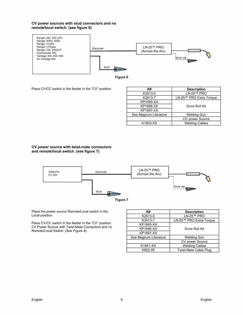
CV power sources with stud connectors and no remote/local switch. (see figure 6)
Figure 6
Place CV/CC switch in the feeder in the "CV" position.
K# Description
K2613-5 LN-25™ PRO K2613-7 LN-25™ PRO Extra Torque
KP1695-XX Drive Roll Kit KP1696-XX
KP1697-XX See Magnum Literature Welding Gun
CC power Source K1803-XX Welding Cables
CV power source with twist-mate connectors and remote/local switch. (see figure 7)
Figure 7
Place the power source Remote/Local switch in the Local position. Place CV/CC switch in the feeder in the “CV” position. CV Power Source with Twist-Mate Connectors and no Remote/Local Switch. (See Figure 8)
K# Description
K2613-5 LN-25™ PRO K2613-7 LN-25™ PRO Extra Torque
KP1695-XX Drive Roll Kit KP1696-XX
KP1697-XX See Magnum Literature Welding Gun
CV power Source K1841-XX Welding Cables K852-95 Twist-Mate Cable Plug
Ranger 250, 250 LPG Ranger 305G, 305D Ranger 10,000 Ranger 3 Phase Ranger 225, 225GXT Commander 300 Vantage 300, 400, 500 Air Vantage 500
Electrode
Work
Work clip
LN-25™ PRO(Across the Arc)
V350-Pro CV 305
Electrode
Work
Work clip
LN-25™ PRO(Across the Arc)

English English 10
CV power source with twist-mate connectors and no remote/local switch. (see figure 8)
Figure 8
Place CV/CC switch in the feeder in the "CV" position.
K# Description
K2613-5 LN-25™ PRO K2613-7 LN-25™ PRO Extra Torque
KP1695-XX Drive Roll Kit KP1696-XX
KP1697-XX See Magnum Literature Welding Gun
CV power Source K1841-XX Welding Cables K852-95 Twist-Mate Cable Plug
K484 Jumper Plug kit
CV-250 CV-300 Electrode
Work
Work clip
LN-25™ PRO(Across the Arc)
Jumper

English English 11
Graphic symbols that appear on this machine or in this manual
INPUT POWER
ON
OFF
WIRE FEEDER
POSITIVE OUTPUT
NEGATIVE OUTPUT
INPUT POWER
DIRECT CURRENT
OPEN CIRCUIT VOLTAGE
INPUT VOLTAGE
OUTPUT VOLTAGE
INPUT CURRENT
OUTPUT CURRENT
PROTECTIVE GROUND
WARNING OR CAUTION
Definition of welding terms WFS • Wire Feed Speed CC • Constant Current CV • Constant Voltage GMAW • Gas Metal Arc welding SMAW • Shielded Metal Arc welding FCAW • Flux Core Arc Welding
General description General physical description The LN-25™ PRO is specially engineered to be the most rugged portable wire feeder available. Several models of the LN-25™ PRO are offered to best meet individual welder needs. The Extra Torque model features additional torque gearing for reliable feeding of large diameter FCAW wires. The Standard and Dual Power models feature wire drive gearing for great performance for both FCAW and GMAW wires of common sizes. All of the models include a gas solenoid for the flexibility to run most wire processes. The plastic case is molded from a high impact, flame retardant plastic for durability and low weight. The heart of the LN-25™ PRO is the 2 roll MAX-TRAC™ drive. The patented features on the wire drive offer tool-less changing of the drive rolls and wire guides for quick spool changes. A tachometer controlled motor powers the patented drive rolls for smooth, steady feeding without slippage. With a 450 amp, 60% duty cycle rating, these feeders are ready for heavy duty welding. General functional description All LN-25™ PRO’s have adjustable WFS range for improving the knob sensitivity. The low range is great for critical welds with Innershield wires, and the upper range is suitable for general purpose welding. Selection of the WFS range is by a rocker switch or through the set-up menu on meters with digital displays.
Recommended processes • GMAW • FCAW
English English 12
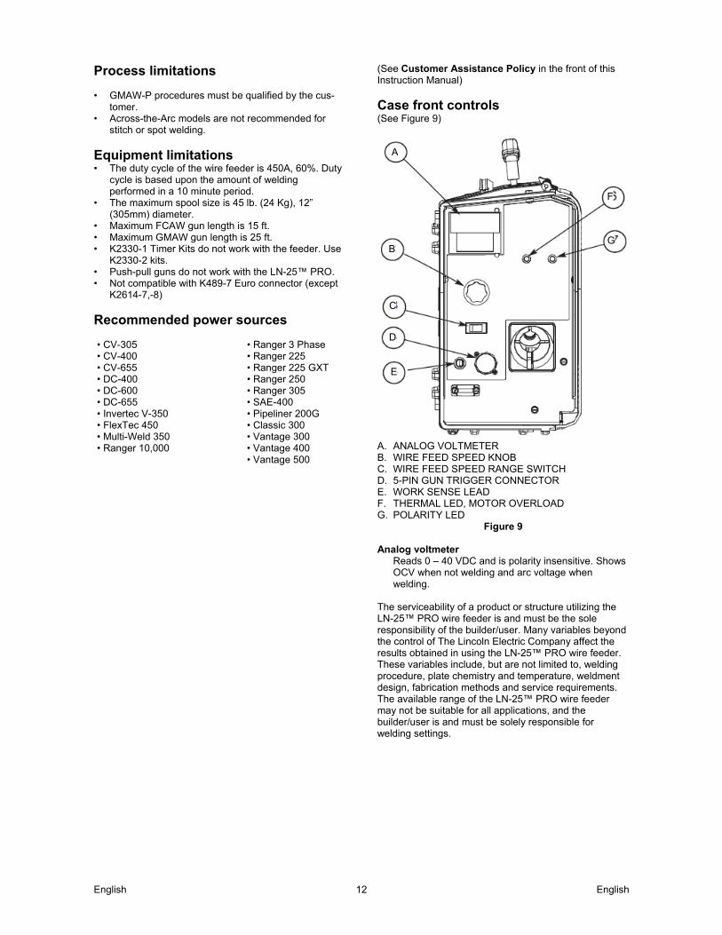
Process limitations • GMAW-P procedures must be qualified by the cus-
tomer. • Across-the-Arc models are not recommended for
stitch or spot welding.
Equipment limitations • The duty cycle of the wire feeder is 450A, 60%. Duty
cycle is based upon the amount of welding performed in a 10 minute period.
• The maximum spool size is 45 lb. (24 Kg), 12” (305mm) diameter.
• Maximum FCAW gun length is 15 ft. • Maximum GMAW gun length is 25 ft. • K2330-1 Timer Kits do not work with the feeder. Use
K2330-2 kits. • Push-pull guns do not work with the LN-25™ PRO. • Not compatible with K489-7 Euro connector (except
K2614-7,-8)
Recommended power sources • CV-305 • Ranger 3 Phase • CV-400 • Ranger 225 • CV-655 • Ranger 225 GXT • DC-400 • Ranger 250 • DC-600 • Ranger 305 • DC-655 • SAE-400 • Invertec V-350 • Pipeliner 200G • FlexTec 450 • Classic 300 • Multi-Weld 350 • Vantage 300 • Ranger 10,000 • Vantage 400 • Vantage 500
(See Customer Assistance Policy in the front of this Instruction Manual)
Case front controls (See Figure 9)
A. ANALOG VOLTMETER B. WIRE FEED SPEED KNOB C. WIRE FEED SPEED RANGE SWITCH D. 5-PIN GUN TRIGGER CONNECTOR E. WORK SENSE LEAD F. THERMAL LED, MOTOR OVERLOAD G. POLARITY LED
Figure 9 Analog voltmeter
Reads 0 – 40 VDC and is polarity insensitive. Shows OCV when not welding and arc voltage when welding.
The serviceability of a product or structure utilizing the LN-25™ PRO wire feeder is and must be the sole responsibility of the builder/user. Many variables beyond the control of The Lincoln Electric Company affect the results obtained in using the LN-25™ PRO wire feeder. These variables include, but are not limited to, welding procedure, plate chemistry and temperature, weldment design, fabrication methods and service requirements. The available range of the LN-25™ PRO wire feeder may not be suitable for all applications, and the builder/user is and must be solely responsible for welding settings.
A
B
C
D
E
F
G
English English 13
CV OPERATION
Minimum Arc Volts
Maximum WFS (Standard Torque)
Maximum WFS (Extra Torque )
15 V 400 220 17 V 450 250 21 V 570 300 24 V 650 350 27 V 700 400
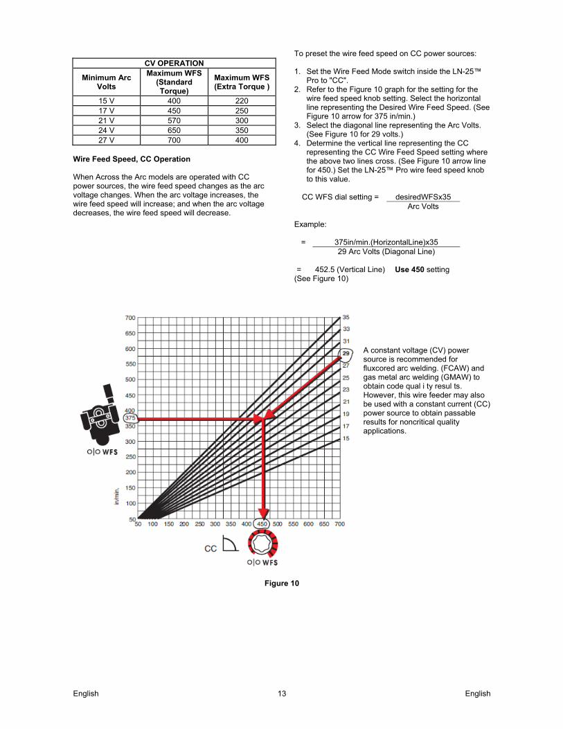
Wire Feed Speed, CC Operation When Across the Arc models are operated with CC power sources, the wire feed speed changes as the arc voltage changes. When the arc voltage increases, the wire feed speed will increase; and when the arc voltage decreases, the wire feed speed will decrease.
To preset the wire feed speed on CC power sources: 1. Set the Wire Feed Mode switch inside the LN-25™
Pro to "CC". 2. Refer to the Figure 10 graph for the setting for the
wire feed speed knob setting. Select the horizontal line representing the Desired Wire Feed Speed. (See Figure 10 arrow for 375 in/min.)
3. Select the diagonal line representing the Arc Volts. (See Figure 10 for 29 volts.)
4. Determine the vertical line representing the CC representing the CC Wire Feed Speed setting where the above two lines cross. (See Figure 10 arrow line for 450.) Set the LN-25™ Pro wire feed speed knob to this value.
CC WFS dial setting = desiredWFSx35
Arc Volts Example:
= 375in/min.(HorizontalLine)x35 29 Arc Volts (Diagonal Line)
= 452.5 (Vertical Line) Use 450 setting
(See Figure 10)
A constant voltage (CV) power source is recommended for fluxcored arc welding. (FCAW) and gas metal arc welding (GMAW) to obtain code qual i ty resul ts. However, this wire feeder may also be used with a constant current (CC) power source to obtain passable results for noncritical quality applications.
Figure 10
English English 14
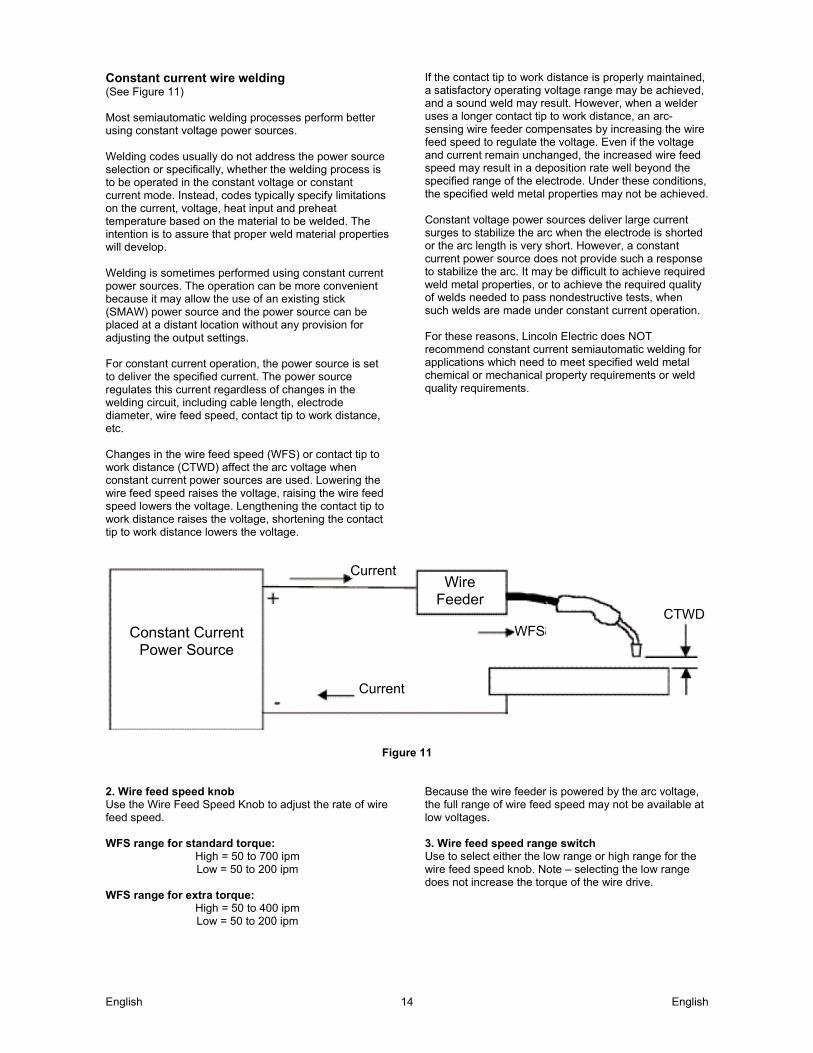
Constant current wire welding (See Figure 11) Most semiautomatic welding processes perform better using constant voltage power sources. Welding codes usually do not address the power source selection or specifically, whether the welding process is to be operated in the constant voltage or constant current mode. Instead, codes typically specify limitations on the current, voltage, heat input and preheat temperature based on the material to be welded. The intention is to assure that proper weld material properties will develop. Welding is sometimes performed using constant current power sources. The operation can be more convenient because it may allow the use of an existing stick (SMAW) power source and the power source can be placed at a distant location without any provision for adjusting the output settings. For constant current operation, the power source is set to deliver the specified current. The power source regulates this current regardless of changes in the welding circuit, including cable length, electrode diameter, wire feed speed, contact tip to work distance, etc. Changes in the wire feed speed (WFS) or contact tip to work distance (CTWD) affect the arc voltage when constant current power sources are used. Lowering the wire feed speed raises the voltage, raising the wire feed speed lowers the voltage. Lengthening the contact tip to work distance raises the voltage, shortening the contact tip to work distance lowers the voltage.
If the contact tip to work distance is properly maintained, a satisfactory operating voltage range may be achieved, and a sound weld may result. However, when a welder uses a longer contact tip to work distance, an arc-sensing wire feeder compensates by increasing the wire feed speed to regulate the voltage. Even if the voltage and current remain unchanged, the increased wire feed speed may result in a deposition rate well beyond the specified range of the electrode. Under these conditions, the specified weld metal properties may not be achieved. Constant voltage power sources deliver large current surges to stabilize the arc when the electrode is shorted or the arc length is very short. However, a constant current power source does not provide such a response to stabilize the arc. It may be difficult to achieve required weld metal properties, or to achieve the required quality of welds needed to pass nondestructive tests, when such welds are made under constant current operation. For these reasons, Lincoln Electric does NOT recommend constant current semiautomatic welding for applications which need to meet specified weld metal chemical or mechanical property requirements or weld quality requirements.
Figure 11
2. Wire feed speed knob Use the Wire Feed Speed Knob to adjust the rate of wire feed speed. WFS range for standard torque:
High = 50 to 700 ipm Low = 50 to 200 ipm
WFS range for extra torque:
High = 50 to 400 ipm Low = 50 to 200 ipm
Because the wire feeder is powered by the arc voltage, the full range of wire feed speed may not be available at low voltages. 3. Wire feed speed range switch Use to select either the low range or high range for the wire feed speed knob. Note – selecting the low range does not increase the torque of the wire drive.
Wire Feeder
Current
Current
WFSCTWD
Constant Current Power Source

English English 15
4. 5-Pin gun trigger connector There is one circular connector for the gun trigger on the front of the LN-25™ PRO. Note – if the gun trigger is already depressed when the feeder is powered up, the feeder will not activate. Release and then press the gun trigger to begin welding.
Function Pin Wiring 5-pin trigger connector for push-guns only.
A 5 volt supply B Not used C Trigger D Not used E Not used
5. Work sense lead Always turn power off at the welding power source before moving the work sense lead. The work sense lead attaches to the item being welded. 6. Thermal led, motor overload The thermal light illuminates when the wire drive motor draws too much current. If the thermal light illuminates, the wire drive will automatically shutdown for up to 30 seconds to allow the motor to cool. To start welding again, release the gun trigger, inspect the gun cable, liner (and conduit). Clean and make repairs as necessary. Start welding again when the problem has been safely resolved. For best results, keep the gun cable and conduit as straight as possible. Perform regular maintenance and cleaning on the gun liner, conduit and gun. Always use quality electrode, such as L-50 or L-56 from Lincoln Electric. 7. Polarity LED The Polari ty LED lights when the wire feeder is connected for positive polarity. Use the polari ty LED to verify if the wire feeder is connected for the proper polarity.
+ POLARITY POLARDAD - POLARITÉ
Internal controls
A. 2 STEP TRIGGER INTERLOCK SWITCH B. CV / CC SWITCH C. PRESSURE ADJUSTMENT ARM D. OPTIONAL TIMER KIT E. SPOOL RETAINER F. SPINDLE BRAKE G. GUN BUSHING, THUMB SCREW AND SOCKET
HEAD CAP SCREW H. DRIVE HUBS I. COLD FEED PUSHBUTTON
Figure 12
Internal controls description (See Figure 12) 1. 2 Step - Trigger interlock switch The 2 Step - Trigger Interlock switch changes the function of the gun trigger. 2 Step trigger operation turns welding on and off in direct response to the trigger. Trigger Interlock operation allows welding to continue when the trigger is released for comfort on long welds. Place the toggle switch in the DOWN position for 2 Step operation or in the UP position for Trigger Interlock operation. 2 Step Trigger 2 Step trigger operation is the most common. When the gun trigger is pulled, the welding power source energizes the electrode output and the wire feeder feeds wire for welding. The power source and wire feeder continue welding until the trigger is released. Trigger Interlock Trigger Interlock operation provides for operator comfort when making long welds. When the gun trigger is first pulled, the welding power source energizes the output and the wire feeder feeds wire for welding. The gun trigger is then released while the weld is made. To stop welding, the gun trigger is pulled again, and when it is released the welding power source output turns off and the wire feeder stops feeding wire.
AB C
D E F
G
H I

English English 16
WARNING If the arc goes out while welding with trigger interlock operation, the electrode output from the welding power source remains energized and the wire feeder will continue to feed wire until the gun trigger is again pulled and then released. 2. CV/CC switch The CV/CC switch sets the wire feed speed control method for the wire feeder. In the CV position, the wire feed speed remains constant during welding. A steady arc voltage is regulated by the power source by adjusting the arc current. In the CC position, the wire feed speed varies during welding. The arc length is maintained by changing the wire feed speed. 3. Pressure arm and adjustment (See installation section) 4. Optional timer kit The optional Timer Kit provides control of preflow time, burnback, and postflow time. 5. Spool retainer To release the spool retainer, squeeze the metal bar inwards. When securing the spool, verify the spool retainer is fully seated in place in one of the three grooves of the spindle. 6. Spool brake Adjust the spool brake to provide enough friction to stop wire overrun. Excessive brake force may cause motor thermal overloads or welding problems. 7. Gun bushing, thumb screw and socket head cap screw (SEE INSTALLATION SECTION) 8. Drive rolls and wire guides (See installation section) 9. Cold feed pushbutton When cold feeding, the wire drive will feed electrode but neither the power source nor the gas solenoid will be energized. Adjust the speed of cold feeding by rotating the WFS knob. Cold feeding, or "cold inching" the electrode is useful for threading the electrode through the gun.
Rear controls: (See Figure 13) 1. Gas purge pushbutton The gas solenoid valve will energize but neither the power source output nor the drive motor will be turned on. The Gas Purge switch is useful for setting the proper flow rate of shielding gas. Flow meters should always be adjusted while the shielding gas is flowing.
A. GAS PURGE PUSHBUTTON B. SHIELDING GAS INLET C. ELECTRODE LEAD
Figure 13
A
B
C
English English 17
Maintenance
Safety precautions
WARNING ELECTRIC SHOCK CAN KILL. • Turn the input power OFF at the welding power
source before installation or changing drive rolls and/or guides.
• Do not touch electrically live parts. • When inching with the gun trigger, electrode and
drive mechanism are "hot" to work and ground and could remain energized several seconds after the gun trigger is released.
• Do not operate with covers, panels or guards removed or open.
• Only qualified personnel should perform mainte nance work.
Routine maintenance • Check weld cables, control cables and gas hoses for
cuts. • Clean and tighten all weld terminals. Periodic maintenance • Clean drive rolls and inner wire guide and replace if
worn. • Blow out or vacuum the inside of the feeder. • Inspect the motor brushes every 6 months. Replace
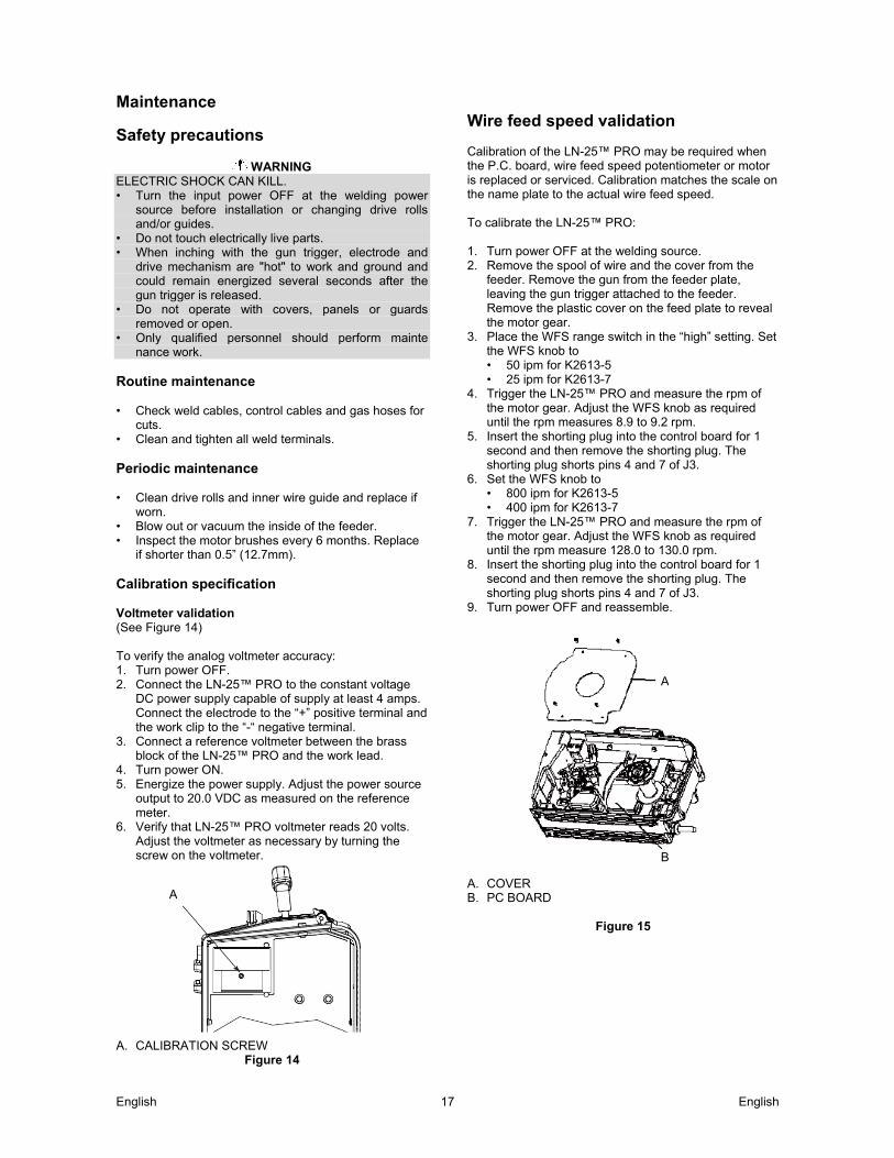
if shorter than 0.5” (12.7mm). Calibration specification Voltmeter validation (See Figure 14) To verify the analog voltmeter accuracy: 1. Turn power OFF. 2. Connect the LN-25™ PRO to the constant voltage
DC power supply capable of supply at least 4 amps. Connect the electrode to the “+” positive terminal and the work clip to the “-“ negative terminal.
3. Connect a reference voltmeter between the brass block of the LN-25™ PRO and the work lead.
4. Turn power ON. 5. Energize the power supply. Adjust the power source
output to 20.0 VDC as measured on the reference meter.
6. Verify that LN-25™ PRO voltmeter reads 20 volts. Adjust the voltmeter as necessary by turning the screw on the voltmeter.
A. CALIBRATION SCREW
Figure 14
Wire feed speed validation Calibration of the LN-25™ PRO may be required when the P.C. board, wire feed speed potentiometer or motor is replaced or serviced. Calibration matches the scale on the name plate to the actual wire feed speed. To calibrate the LN-25™ PRO: 1. Turn power OFF at the welding source. 2. Remove the spool of wire and the cover from the
feeder. Remove the gun from the feeder plate, leaving the gun trigger attached to the feeder. Remove the plastic cover on the feed plate to reveal the motor gear.
3. Place the WFS range switch in the “high” setting. Set the WFS knob to • 50 ipm for K2613-5 • 25 ipm for K2613-7
4. Trigger the LN-25™ PRO and measure the rpm of the motor gear. Adjust the WFS knob as required until the rpm measures 8.9 to 9.2 rpm.
5. Insert the shorting plug into the control board for 1 second and then remove the shorting plug. The shorting plug shorts pins 4 and 7 of J3.
6. Set the WFS knob to • 800 ipm for K2613-5 • 400 ipm for K2613-7
7. Trigger the LN-25™ PRO and measure the rpm of the motor gear. Adjust the WFS knob as required until the rpm measure 128.0 to 130.0 rpm.
8. Insert the shorting plug into the control board for 1 second and then remove the shorting plug. The shorting plug shorts pins 4 and 7 of J3.
9. Turn power OFF and reassemble.
A. COVER B. PC BOARD
Figure 15
A
A
B

English English 18
WEEE 07/06
En
glis
h
Do not dispose of electrical equipment together with normal waste! In observance of European Directive 2012/19/EC on Waste Electrical and Electronic Equipment (WEEE) and its implementation in accordance with national law, electrical equipment that has reached the end of its life must be collected separately and returned to an environmentally compatible recycling facility. As the owner of the equipment, you should get information on approved collection systems from our local representative. By applying this European Directive you will protect the environment and human health!
Spare Parts 12/05
For Spare Parts references visit the Web page: https://www.lincolnelectric.com/LEExtranet/EPC/
Authorized Service Shops Location 09/16
The purchaser must contact a Lincoln Authorized Service Facility (LASF) about any defect claimed under Lincoln's warranty period.
Contact your local Lincoln Sales Representative for assistance in locating a LASF or go to www.lincolnelectric.com/en-gb/Support/Locator.
English English 19
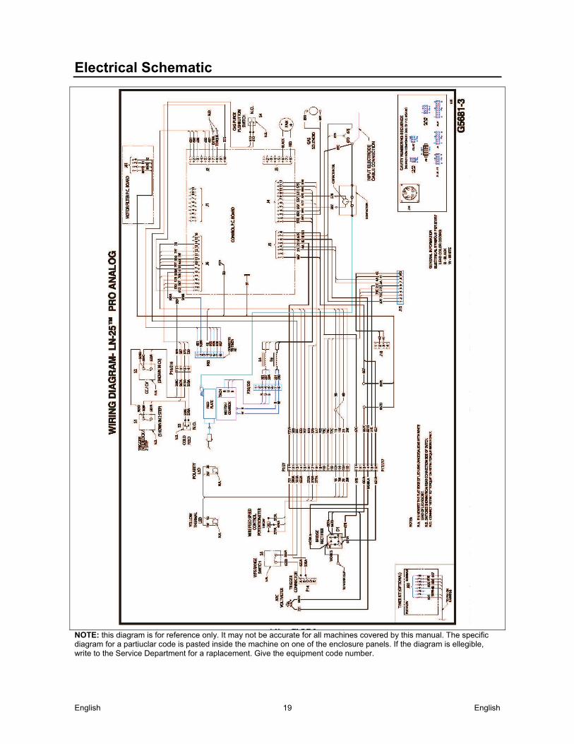
Electrical Schematic
NOTE: this diagram is for reference only. It may not be accurate for all machines covered by this manual. The specific diagram for a partiuclar code is pasted inside the machine on one of the enclosure panels. If the diagram is ellegible, write to the Service Department for a raplacement. Give the equipment code number.
English English 20
Suggested Accessories
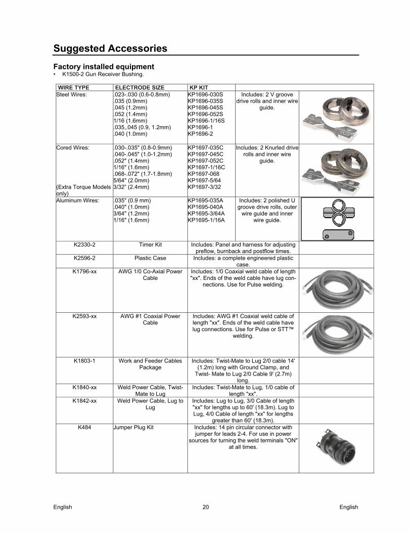
Factory installed equipment • K1500-2 Gun Receiver Bushing.
WIRE TYPE ELECTRODE SIZE KP KIT Steel Wires: .023-.030 (0.6-0.8mm)
.035 (0.9mm)
.045 (1.2mm)
.052 (1.4mm) 1/16 (1.6mm) .035,.045 (0.9, 1.2mm) .040 (1.0mm)
KP1696-030S KP1696-035S KP1696-045S KP1696-052S KP1696-1/16S KP1696-1 KP1696-2
Includes: 2 V groove drive rolls and inner wire
guide.
Cored Wires: .030-.035" (0.8-0.9mm) .040-.045" (1.0-1.2mm) .052" (1.4mm) 1/16" (1.6mm) .068-.072" (1.7-1.8mm) 5/64" (2.0mm) 3/32” (2.4mm)
KP1697-035C KP1697-045C KP1697-052C KP1697-1/16C KP1697-068 KP1697-5/64 KP1697-3/32
Includes: 2 Knurled drive rolls and inner wire
guide.
(Extra Torque Models only) Aluminum Wires: .035" (0.9 mm)
.040" (1.0mm) 3/64" (1.2mm) 1/16" (1.6mm)
KP1695-035A KP1695-040A KP1695-3/64A KP1695-1/16A
Includes: 2 polished U groove drive rolls, outer
wire guide and inner wire guide.
K2330-2 Timer Kit Includes: Panel and harness for adjusting preflow, burnback and postflow times.
K2596-2 Plastic Case Includes: a complete engineered plastic case.
K1796-xx AWG 1/0 Co-Axial Power Cable
Includes: 1/0 Coaxial weld cable of length "xx". Ends of the weld cable have lug con-
nections. Use for Pulse welding.
K2593-xx AWG #1 Coaxial Power Cable
Includes: AWG #1 Coaxial weld cable of length "xx". Ends of the weld cable have lug connections. Use for Pulse or STT™
welding.
K1803-1 Work and Feeder Cables Package
Includes: Twist-Mate to Lug 2/0 cable 14' (1.2m) long with Ground Clamp, and
Twist- Mate to Lug 2/0 Cable 9' (2.7m) long.
K1840-xx Weld Power Cable, Twist-Mate to Lug
Includes: Twist-Mate to Lug, 1/0 cable of length "xx".
K1842-xx Weld Power Cable, Lug to Lug
Includes: Lug to Lug, 3/0 Cable of length "xx" for lengths up to 60' (18.3m). Lug to Lug, 4/0 Cable of length "xx" for lengths
greater than 60' (18.3m).
K484 Jumper Plug Kit Includes: 14 pin circular connector with jumper for leads 2-4. For use in power
sources for turning the weld terminals "ON" at all times.

English English 21
K910-1 Ground Clamp Includes: One 300 Amp Ground Clamp.
K910-2 Ground Clamp Includes: One 500 Amp Ground Clamp.
K1500-1 Gun Receiver Bushing (for guns with K466-1 Lincoln
gun connectors; Innershield and Subarc guns)
Includes: Gun receiver bushing, set screw and hex key wrench.
K1500-2 Gun Receiver Bushing (for guns with K466-2, K466-10
Lincoln gun connectors; Magnum 200/300/400 guns
and compatible with Tweco® #2-#4)
Includes: Gun receiver bushing with hose nipple, set screw and hex key wrench.
K1500-3 Gun Receiver Bushing (for guns with K613-7 Lincoln gun connectors; Magnum 550 guns and compatible
with Tweco® #5)
Includes: Gun receiver bushing with hose nipple, set screw and hex key wrench.
K1500-4 Gun Receiver Bushing (for gun with K466-3 Lincoln
gun connectors; compatible with Miller® guns.)
Includes: Gun receiver bushing with hose nipple, set screw and hex key wrench.
K1500-5 Gun Receiver Bushing (compatible with Oxo®
guns.)
Includes: Gun receiver bushing with hose nipple, 4 guide tubes, set screw and hex
key wrench.
K435 Spindle Adapter, for mounting 14 lb. (6.4 kg) Innershield Coils on 2 in
(51 mm) spindles.
Includes: Spindle Adapter made from 2 coil retainers. (Electrode not included.)
K468 Spindle Adapter, for mounting 8in (203mm)
diameter spools on 2 in (51 mm) spindles.
Includes: 2 Spindle Adapters, one for 2" wide spools and the other for 3" wide
spools.
K590-6 Water Connection Kit (for European and Control
cable models only)
Includes: 2 hoses with female quick connectors at each end, 2 male
connectors for 3/16" ID hose, 2 male connectors for _" ID hose, and mounting
hardware.
K586-1 Deluxe Adjustable Gas Regulator
Includes: Deluxe Gas Regulator for Mixed Gases, Adapter for CO2 and 10' (3.0m)
Hose.
K283 Wire Feed Speed Meter Includes: A wire feed speed meter with digital display.