rev: r1 page 1 / 20 - red sísmica de puerto...
TRANSCRIPT

WX14 EMWIN Data Receive System Project : WX14 Satellite Receiver UM-1002
Rev: R1 Page 1 / 20
Copyright Zephyrus Electronics 2013. All rights reserved. This document and all information contained herein are confidential and proprietary and may not be copied or transferred in whole or in part
to any person not the original recipient without the express written consent of Zephyrus.
WX14 EMWIN RECEIVE SYSTEM

WX14 EMWIN Data Receive System Project : WX14 Satellite Receiver UM-1002
Rev: R1 Page 2 / 20
Copyright Zephyrus Electronics 2013. All rights reserved. This document and all information contained herein are confidential and proprietary and may not be copied or transferred in whole or in part
to any person not the original recipient without the express written consent of Zephyrus.
1 Revisions
Revision history
Revision Description Date By
R1 Initial Release – Document UM-1002 03/08/13 PW

WX14 EMWIN Data Receive System Project : WX14 Satellite Receiver UM-1002
Rev: R1 Page 3 / 20
Copyright Zephyrus Electronics 2013. All rights reserved. This document and all information contained herein are confidential and proprietary and may not be copied or transferred in whole or in part
to any person not the original recipient without the express written consent of Zephyrus.
TABLE OF CONTENTS 1 Revisions .............................................................................................................................................. 2 2 Introduction ........................................................................................................................................... 4 3 Package Contents ................................................................................................................................. 6
3.1 Box 1 ................................................................................................................................................ 6 3.2 Box 2 - Optional ................................................................................................................................ 6
4 Specifications ........................................................................................................................................ 7 5 WX-14 Receiver Operation .................................................................................................................... 8
5.1 Receiver Mode ................................................................................................................................. 8 5.1.1 Normal Mode ............................................................................................................................. 8
5.1.1.1 Signal Level ........................................................................................................................... 8 5.1.1.2 Receiver Lock ........................................................................................................................ 8 5.1.1.3 Signal Quality ......................................................................................................................... 8 5.1.1.4 System Status: ....................................................................................................................... 8 5.1.1.5 Error:...................................................................................................................................... 8
5.1.2 Dish Align Mode ........................................................................................................................ 9 5.1.2.1 Top Row – Signal Level.......................................................................................................... 9 5.1.2.2 Bottom Row – Signal Acquisition ............................................................................................ 9
5.1.3 Receiver Connections .............................................................................................................. 10 5.1.3.1 RF Input ............................................................................................................................... 10 5.1.3.2 Power .................................................................................................................................. 10 5.1.3.3 Data and Control .................................................................................................................. 10
6 Assembly ............................................................................................................................................ 11 6.1 Grid Antenna .................................................................................................................................. 11
6.1.1 Grid Reflector Assembly .......................................................................................................... 11 6.1.2 Attach Reflector to Azimuth/Elevation/Skew Plate Mount ......................................................... 12 6.1.3 Attach Antenna Center Feed Post ............................................................................................ 12 6.1.4 Attach Antenna Center Feed Post - Continued ......................................................................... 13 6.1.5 Finished Antenna Assembly ..................................................................................................... 13
6.2 Optional – Tripod Antenna Mount ................................................................................................... 14 6.2.1 Attach Concrete Block Holders ................................................................................................ 14 6.2.2 Attach Antenna Mast ............................................................................................................... 15 6.2.3 Attach Antenna Assembly to Mast Post .................................................................................... 16 6.2.4 Attach LNA .............................................................................................................................. 16
6.3 Optional – Rectangular Antenna Mount ........................................................................................... 17 6.3.1 Antenna Mount Assembly ........................................................................................................ 17 6.3.2 Attach Grid Antenna Assembly ................................................................................................ 18 6.3.3 Attach LNA .............................................................................................................................. 18
7 Antenna Setup .................................................................................................................................... 19 7.1 Determine “Look Angle” .................................................................................................................. 19 7.2 Choose Antenna Location ............................................................................................................... 19 7.3 Set the Antenna Elevation .............................................................................................................. 19 7.4 Set the Antenna Polarization Skew ................................................................................................. 20 7.5 Set the Antenna Azimuth. ............................................................................................................... 20

WX14 EMWIN Data Receive System Project : WX14 Satellite Receiver UM-1002
Rev: R1 Page 4 / 20
Copyright Zephyrus Electronics 2013. All rights reserved. This document and all information contained herein are confidential and proprietary and may not be copied or transferred in whole or in part to any
person not the original recipient without the express written consent of Zephyrus.
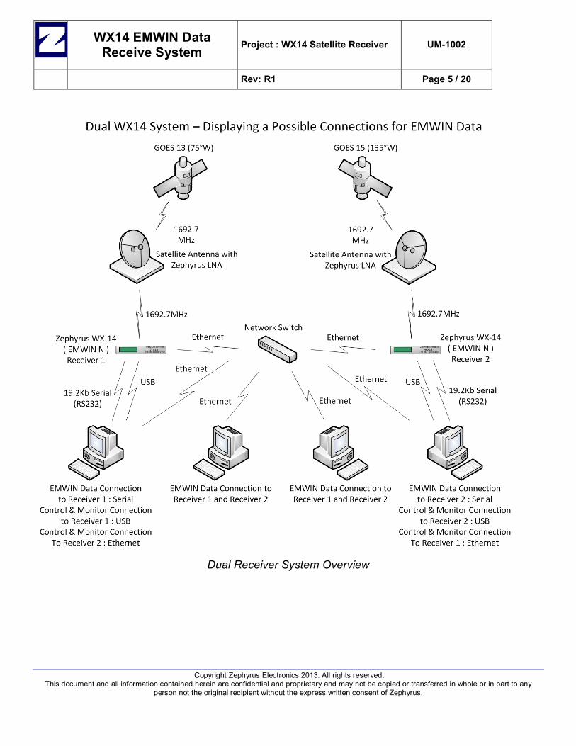
2 Introduction The purpose of this document is to provide assembly, installation, and setup instructions for the WX-14 EMWIN Data Receive System. The receive system consists of the Grid antenna, WX-14 EMWIN Data Receiver, and miscellaneous interconnecting cables. Single and dual receiver configurations are possible and shown below in the system overview diagrams. NOTE: The Network Switch and Computers are not included with the system and are shown below to better visualize end user configurations.
Single Receiver System Overview
WX14 EMWIN Data Receive System Project : WX14 Satellite Receiver UM-1002
Rev: R1 Page 5 / 20
Copyright Zephyrus Electronics 2013. All rights reserved. This document and all information contained herein are confidential and proprietary and may not be copied or transferred in whole or in part to any
person not the original recipient without the express written consent of Zephyrus.
Dual Receiver System Overview

WX14 EMWIN Data Receive System Project : WX14 Satellite Receiver UM-1002
Rev: R1 Page 6 / 20
Copyright Zephyrus Electronics 2013. All rights reserved. This document and all information contained herein are confidential and proprietary and may not be copied or transferred in whole or in part to any
person not the original recipient without the express written consent of Zephyrus.
3 Package Contents The Zephyrus WX-14 Receive System will be shipped in two containers. One box will contain the electronic components and the grid reflector and center post feed components of the antenna. The second box will contain the heavier metal components of the antenna mounting system.
3.1 Box 1 QTY Description 1 WX-14 Satellite Receiver 1 WX-14 Software Disc 1 AC to DC Power Adapter 1 Serial (RS232) Data Cable – DB9F to DB9M 1 USB Data Cable – USB “A” to USB “B” 1 Ethernet Data Cable – RJ45 to RJ45 1 Coax Cable – 100’, RG6, “F” to “F” 1 Antenna Reflector, Grid w/ Hardware 1 Antenna / Center Feed Post 1 Azimuth/Elevation/Skew Plate Antenna Mount Assembly 1 8mm Wrench 1 10mm Wrench 1 13mm Wrench 1 Pliers
3.2 Box 2 - Optional QTY Description 1 Non-Penetrating Roof Antenna Mount w/Hardware

WX14 EMWIN Data Receive System Project : WX14 Satellite Receiver UM-1002
Rev: R1 Page 7 / 20
Copyright Zephyrus Electronics 2013. All rights reserved. This document and all information contained herein are confidential and proprietary and may not be copied or transferred in whole or in part to any
person not the original recipient without the express written consent of Zephyrus.
4 Specifications Power: 24VDC, 3Amp AC/DC “Wall” adapter is supplied with the receiver. Connector on receiver is a “Captive Screw Lock” DC Jack which, when used appropriately, will prevent an accidental power disconnect. RF Input: 1692.7MHz, (-105dbm) to (-60dbm). Connector Type: "F", 75 ohm Impedance on rear panel of receiver and connects to the Zephyrus LNA. Data I/O Connections: USB: A USB "B" connector located on rear panel is provided to connect the receiver to a computer for receiver control and monitoring. EMWIN “N” Data on this port is mixed with receiver status information allowing the WX-14 software to show receiver status as well as EMWIN Data Quality, if selected. An “Independent Software Programmers” message protocol document is available for Weather Alert Software authors wanting to utilize EMWIN Data input through USB connectivity. Serial Data Output: RS232, 19.2kb EMWIN “N” Data. No Handshake. Connector: DB9 Female. EMWIN Data is present on this port as long as signal is good enough for receiver to lock onto and demodulate data. Ethernet: Factory Default IP Address is 192.168.0.50. There are two port connections available.
• Control Port = 7002. This port is used to establish a receiver “Control Connection” which is used for both status and control. There may be up to two simultaneous connections to this port.
• Data Port = 7003. This port is used for EMWIN “N” Data. There may be up to two simultaneous connections to this port.
Mode Switch: Rocker switch on rear panel selects between “Normal mode and “Dish Align Mode”. This causes the display on the front panel to change allowing it to be used for antenna positioning or for status monitoring. LCD Display: A dual row, backlit Liquid Crystal Display (LCD) on the front panel. It provides the user with signal and hardware status information and displays information differently depending on what Mode the receiver is in.
• Normal Mode – In this mode the LCD shows signal level, signal lock status, signal quality, and internal system status.
• Dish Align Mode – In this mode the receiver shows signal level in bar graph form, Internal Oscillator Lock, Viterbi Decoder Lock, VCDU Frame Synchronization, and Signal Quality in bar graph form.
Rack Mount Option: A 1RU Rack Panel designed to hold either one or two WX-14 receivers. Antenna: Custom designed Di-Pole; parabolic grid reflector
• Frequency – 1692.7 MHz • GAIN – 18dbi • Mount – Adjustable Azimuth, Elevation, and Polarization Skew. Accepts 2” diameter pole.
LNA: Gain = approximately 25db. Connectors = 75 ohm “F” connectors. Housing = sealed, anodized aluminum. Cable: 100' of RG6 is included. Maximum cable length will vary due to your location, antenna alignment, condition of antenna, condition of cable, condition of cable connections, and levels of possible RF interference. Taking all this into consideration and if you are not on the fringes of the satellite "footprint", you should be able to run 300 to 350 feet of RG6 cable without additional amplification.

WX14 EMWIN Data Receive System Project : WX14 Satellite Receiver UM-1002
Rev: R1 Page 8 / 20
Copyright Zephyrus Electronics 2013. All rights reserved. This document and all information contained herein are confidential and proprietary and may not be copied or transferred in whole or in part to any
person not the original recipient without the express written consent of Zephyrus.
5 WX-14 Receiver Operation
5.1 Receiver Mode The WX-14 has two modes of operation, “Normal Mode” and “Dish Align Mode”. The mode switch on the rear panel of the receiver switches modes of operation. Software is also provided with the WX-14 Receiver and may be used for monitoring and to set user configurable receiver parameters, though the software it is not required for receiver function.
5.1.1 Normal Mode Normal Mode changes the receiver display on the front panel to show specific information regarding signal reception and system is the mode the receiver should always be kept in unless the receiver is specifically being used to align the antenna (Dish).
Figure 6-1:Normal Mode showing Good Signal
Figure 6-2:Normal Mode showing No Signal
5.1.1.1 Signal Level • “S:1.79” = Signal level = Voltage level at A/D Converter Input. The AGC will attempt to keep this at
approximately 1.80 and will always fluctuate slightly. This level will decrease as the input level to the receiver drops below a threshold that the AGC can no longer compensate for. This is relative level meter ONLY and is not an indication of Signal Quality or EMWIN Data Quality.
5.1.1.2 Receiver Lock • “L” = Viterbi Lock and VCDU Frame Synchronization.
5.1.1.3 Signal Quality • “Q:100” = Signal Quality = A running display value derived from the ratio of corrected bytes to received VCDU
frames in a given time frame. This number will fluctuate occasionally; however, if your dish is properly aligned, cable connections are good, Signal Level is high enough, and there is no overwhelming signal interference, then you should see “100” most of the time. NOTE: This is not EMWIN Data Quality. Signal quality can be less than 100 and EMWIN Data Quality can still be at or close to 100% meaning the forward error correction is properly correcting bytes as needed.
5.1.1.4 System Status: • “System OK” = Internal system is OK. Not related to signal.
5.1.1.5 Error: • “E” = No signal or signal reception is too bad. The receiver cannot lock to and decode data.

WX14 EMWIN Data Receive System Project : WX14 Satellite Receiver UM-1002
Rev: R1 Page 9 / 20
Copyright Zephyrus Electronics 2013. All rights reserved. This document and all information contained herein are confidential and proprietary and may not be copied or transferred in whole or in part to any
person not the original recipient without the express written consent of Zephyrus.
5.1.2 Dish Align Mode “Dish Align” mode is activated by a rocker switch on the rear panel of the receiver. This will change the display to show signal information in a bar graph form. This information may be used to aim the antenna to the satellite.
Figure 6-3
Dish Align Mode showing Good Signal
Figure 6-4
Dish Align Mode showing No Signal
5.1.2.1 Top Row – Signal Level The top row of the display is used for signal level indication. This is used to fine tune the antenna after signal lock has been established.
• “Sx3” = Bar Graph Scale Factor. It changes the bar graph scale so that it is usable when using a very short cable or a very long cable while aligning the dish. Do not put too much emphasis on this.
• “Bar Graph” = Signal Level – The Bar Graph is a relative level meter representing voltage level at input of A/D
converter. Use this level for fine tuning dish alignment once you have signal lock. You want as many bars as possible regardless of the “multiplier” number shown.
5.1.2.2 Bottom Row – Signal Acquisition The bottom row of the display is used for signal acquisition status: THIS IS MOST IMPORTANT AND SHOULD BE USED TO “FIND” THE SIGNAL!
• “F” = Frequency Lock - This is there all the time and represents VCXO frequency internally.
• “L” = Viterbi Decoder Lock
• “V” = VCDU Frame Synchronization
• “Bar Graph” = Signal Quality = Display derived from the ratio of corrected bytes to received VCDU frames. The "FLV" will appear quickly as you pass through the signal while panning the dish. Use this to find the signal.

WX14 EMWIN Data Receive System Project : WX14 Satellite Receiver UM-1002
Rev: R1 Page 10 / 20
Copyright Zephyrus Electronics 2013. All rights reserved. This document and all information contained herein are confidential and proprietary and may not be copied or transferred in whole or in part to any
person not the original recipient without the express written consent of Zephyrus.
5.1.3 Receiver Connections
5.1.3.1 RF Input
• “LNF” = “F” Type connector on the rear panel of the receiver. Connect coax cable from LNF/LNA.
5.1.3.2 Power • “+24 VDC IN” = Screw Locking DC connector on the rear panel of receiver. Connect the AC/DC power supply
provided with the receiver.
5.1.3.3 Data and Control • “RS232 DATA” = DB9 Female connector on the rear panel of the receiver. It provides EMWIN Data Out to
Computer.
• “Ethernet” = RJ45 connector on the rear panel of the receiver. It is a network connection for EMWIN Data and Receiver Status Information.
• “USB” = USB “B” connector on the rear panel of the receiver. Connection to/from computer and used for receiver monitoring and control from the WX-14 Software.

WX14 EMWIN Data Receive System Project : WX14 Satellite Receiver UM-1002
Rev: R1 Page 11 / 20
Copyright Zephyrus Electronics 2013. All rights reserved. This document and all information contained herein are confidential and proprietary and may not be copied or transferred in whole or in part to any
person not the original recipient without the express written consent of Zephyrus.
6 Assembly The Zephyrus WX-14 Receive Antenna is very easy to assemble and setup. It consists of a just a few components and requires minimal tools.
6.1 Grid Antenna
6.1.1 Grid Reflector Assembly • Step 1 - Locate the two reflector halves with
attached hardware. There should be 4 bolts, lock washers, and flat washers.
Figure 4-1
• Step 2 - Separate the two halves and align them on a table across from each other with the 6 tabs facing each other.
Figure 4-2
• Step 3 - Starting at one end, begin to slide the two halves together and work your way toward the other end. It is helpful to insert the first bolt and leave very loose until you get the remaining tabs aligned together. Finish attaching the two halves together using the remaining 3 bolts, lock washers, and flat washers. Use only the 4 outer most tabs and DO NOT TIGHTEN at this point.
Figure 4-3
Figure 4-4
Figure 4-5

WX14 EMWIN Data Receive System Project : WX14 Satellite Receiver UM-1002
Rev: R1 Page 12 / 20
Copyright Zephyrus Electronics 2013. All rights reserved. This document and all information contained herein are confidential and proprietary and may not be copied or transferred in whole or in part to any
person not the original recipient without the express written consent of Zephyrus.
6.1.2 Attach Reflector to Azimuth/Elevation/Skew Plate Mount • Step 1 - Locate the Azimuth/Elevation/Skew Plate assembly and remove the 4 nuts, lock washers, and flat
washers from the 4 studs protruding from the Skew Plate.
• Step 2 - Align the reflector with the 4 studs protruding from the Skew Plate. Push the reflector down over the studs. This may require a bit of wiggle and/or “rocking” gently back and forth.
• Step 3 - Attach the reflector to the Skew Plate using ONLY 2 nuts, lock washers, and flat washers. Tighten the 2
nuts using a 10mm wrench. Tighten the 4 bolts that attach the two grid halves together that were intentionally left loose in the previous step using an 8mm wrench.
Figure 4-6
Figure 4-7
Figure 4-8
6.1.3 Attach Antenna Center Feed Post • Step 1 – Locate Antenna Center Feed Post. Inspect for any damage that may have occurred during shipping
and/or un-packaging. The reflector plate should be secure, symmetrical, and parallel to the plastic end cap it is attached to.
Figure 4-9
Figure 4-10
WX14 EMWIN Data Receive System Project : WX14 Satellite Receiver UM-1002
Rev: R1 Page 13 / 20
Copyright Zephyrus Electronics 2013. All rights reserved. This document and all information contained herein are confidential and proprietary and may not be copied or transferred in whole or in part to any
person not the original recipient without the express written consent of Zephyrus.
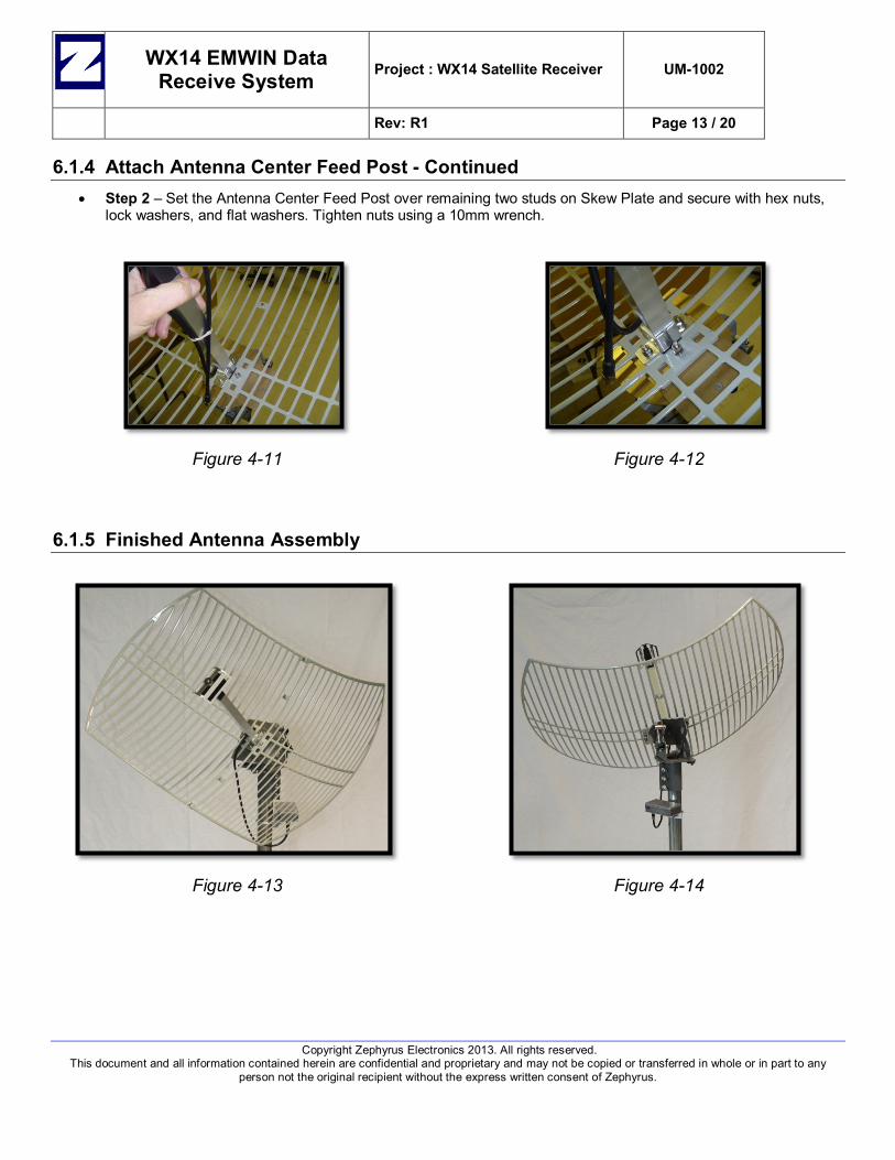
6.1.4 Attach Antenna Center Feed Post - Continued • Step 2 – Set the Antenna Center Feed Post over remaining two studs on Skew Plate and secure with hex nuts,
lock washers, and flat washers. Tighten nuts using a 10mm wrench.
Figure 4-11
Figure 4-12
6.1.5 Finished Antenna Assembly
Figure 4-13
Figure 4-14

WX14 EMWIN Data Receive System Project : WX14 Satellite Receiver UM-1002
Rev: R1 Page 14 / 20
Copyright Zephyrus Electronics 2013. All rights reserved. This document and all information contained herein are confidential and proprietary and may not be copied or transferred in whole or in part to any
person not the original recipient without the express written consent of Zephyrus.
6.2 Optional – Tripod Antenna Mount An optional Tripod Antenna Mount may be packaged with your system. It consists of three main components, the Tripod, the Antenna Mast Post, and Concrete Block Holder Feet.
Figure 4-15
Figure 4-16
6.2.1 Attach Concrete Block Holders • Step 1 – Locate the Tripod Mount, Antenna Mast Post, and Concrete Block Holder Feet and hardware.
Figure 4-17
Figure 4-18

WX14 EMWIN Data Receive System Project : WX14 Satellite Receiver UM-1002
Rev: R1 Page 15 / 20
Copyright Zephyrus Electronics 2013. All rights reserved. This document and all information contained herein are confidential and proprietary and may not be copied or transferred in whole or in part to any
person not the original recipient without the express written consent of Zephyrus.
• Step 2 – Spread the legs of the tripod out so that it stands on all three legs.
• Step 3 - Attach Concrete Block Holder Feet to tripod using hex nuts, lock washers, and flat washers. Tighten using a 10mm wrench.
Figure 4-19
Figure 4-20
6.2.2 Attach Antenna Mast Attach Antenna Mast Post by inserting post through center hole at top of tripod and sliding it down and into the mast post stop bracket. Make sure it is seated all the way to the bottom of the bracket. Tighten bolts (both top and bottom pole clamps) and locking nuts for mast post using a 13mm wrench.
Figure 4-21
Figure 4-22
Figure 4-23

WX14 EMWIN Data Receive System Project : WX14 Satellite Receiver UM-1002
Rev: R1 Page 16 / 20
Copyright Zephyrus Electronics 2013. All rights reserved. This document and all information contained herein are confidential and proprietary and may not be copied or transferred in whole or in part to any
person not the original recipient without the express written consent of Zephyrus.
6.2.3 Attach Antenna Assembly to Mast Post Attach Grid Antenna assembly to mast post by sliding Azimuth/Elevation antenna mount over mast post. Tighten locking bolts using a 13mm wrench.
Figure 4-24
Figure 4-25
6.2.4 Attach LNA The LNA is provided with a pre-attached bracket and a 2” U-Bolt. It should be mounted to the Antenna Mast within 3 to 4 inches of the Azimuth/Elevation/Skew Plate Mount Assembly. Tighten the nuts using a 10mm wrench. NOTE: The Antenna Mast may be one supplied with the Zephyrus WX-14 System or may be user supplied.
Figure 4-26
Figure 4-27
WX14 EMWIN Data Receive System Project : WX14 Satellite Receiver UM-1002
Rev: R1 Page 17 / 20
Copyright Zephyrus Electronics 2013. All rights reserved. This document and all information contained herein are confidential and proprietary and may not be copied or transferred in whole or in part to any
person not the original recipient without the express written consent of Zephyrus.
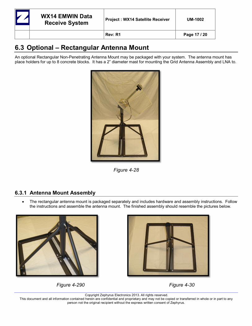
6.3 Optional – Rectangular Antenna Mount An optional Rectangular Non-Penetrating Antenna Mount may be packaged with your system. The antenna mount has place holders for up to 8 concrete blocks. It has a 2” diameter mast for mounting the Grid Antenna Assembly and LNA to.
Figure 4-28
6.3.1 Antenna Mount Assembly • The rectangular antenna mount is packaged separately and includes hardware and assembly instructions. Follow
the instructions and assemble the antenna mount. The finished assembly should resemble the pictures below.
Figure 4-290
Figure 4-30

WX14 EMWIN Data Receive System Project : WX14 Satellite Receiver UM-1002
Rev: R1 Page 18 / 20
Copyright Zephyrus Electronics 2013. All rights reserved. This document and all information contained herein are confidential and proprietary and may not be copied or transferred in whole or in part to any
person not the original recipient without the express written consent of Zephyrus.
6.3.2 Attach Grid Antenna Assembly • Step 1 - Attach the Grid Antenna Assembly to the mast of the Antenna Mount by sliding the antenna assembly
over and down onto the mast post of the antenna mount. Tighten the three 13mm nuts using the 13mm wrench. NOTE: These may be loosened and re-tightened during the antenna to satellite aiming procedure.
Figure 4-31
Figure 4-32
6.3.3 Attach LNA • Step 1 – Attach the LNA to the Mast Post of the antenna mount using the supplied U-Bolt and secure by
tightening the 1/4- 20 hex nuts using a 7/16 wrench.
Figure 4-33
Figure 4-34

WX14 EMWIN Data Receive System Project : WX14 Satellite Receiver UM-1002
Rev: R1 Page 19 / 20
Copyright Zephyrus Electronics 2013. All rights reserved. This document and all information contained herein are confidential and proprietary and may not be copied or transferred in whole or in part to any
person not the original recipient without the express written consent of Zephyrus.
7 Antenna Setup
7.1 Determine “Look Angle” “Look Angle” is a combination of Azimuth, Elevation, and Polarity Skew specific to your location relative to the satellite. You can determine this information by using any online “Look Angle” Calculator. Choose the satellite, which will be either GOES 13 at 75°W or GOES 15 at 135°W. Input your location information and the calculator should give you your Azimuth, Elevation, and Polarization Skew settings. Here is a link to one “Look Angle” calculator, though there are many available online. http://www.groundcontrol.com/Satellite_Look_Angle_Calculator.htm
7.2 Choose Antenna Location • Check for clear line of sight to the satellite. Using the calculated Azimuth and Elevation settings, look towards
that general direction and elevation and make sure there are no trees or buildings or anything else blocking the view to the satellite.
• Place the antenna in selected location and use concrete blocks to weigh it down. A level surface is preferable, but not a must. NOTE: Un-level surface, if severe enough, will affect the elevation and skew settings regarding scale printed on antenna mount.
7.3 Set the Antenna Elevation • There is an Elevation Scale on both sides of the antenna mount and a Red Line on the movable part. Loosen the
three nuts shown below using a 13mm wrench. Adjust the elevation by aligning the red mark with the appropriate elevation and tighten the nuts. The elevation scale is a close approximation and may vary depending on antenna level and may be “Fine Tuned” later.
Figure 5-1
Figure 5-2
Figure 5-3
Figure 5-4
Figure 5-5

WX14 EMWIN Data Receive System Project : WX14 Satellite Receiver UM-1002
Rev: R1 Page 20 / 20
Copyright Zephyrus Electronics 2013. All rights reserved. This document and all information contained herein are confidential and proprietary and may not be copied or transferred in whole or in part to any
person not the original recipient without the express written consent of Zephyrus.
7.4 Set the Antenna Polarization Skew • Loosen the bolt in the center underneath side slightly and the clamp nut shown below.
Figure 5-6
Figure 5-7 • Adjust the Polarization Skew to the approximate angle. This may be “Fine Tuned” later.
Figure 5-8
20° Positive SKEW
Figure 5-9
Zero Degrees
Figure 5-10
20° Negative SKEW
7.5 Set the Antenna Azimuth.
• Loosen the main mount bracket bolts shown below. • Use a compass to find the direction to point the antenna. Remember to use the Magnetic Azimuth from
the “Look Angle” calculator, some calculators give both “True” and “Magnetic” headings. • Rotate the antenna to the “Magnetic Azimuth” heading and tighten the bolts. By definition North is 0°,
East is 90°, South is 180°, and West is 270° deg. North can also be called 360°.
Figure 5-11
Figure 5-12