rev.: f parallel stakeholder review in
TRANSCRIPT
TECHNICAL REVIEW PROCESS KDP-P-2713
Rev.: F
Page 1 of 47
________________________________________
Director, Engineering
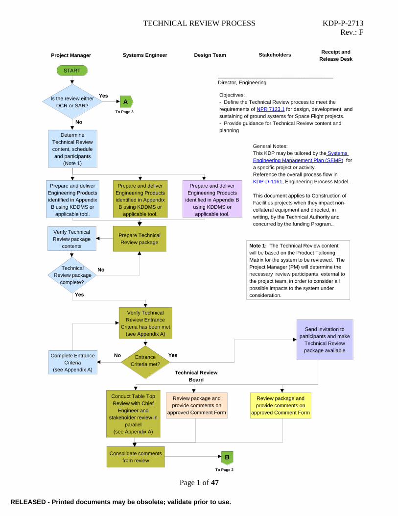
Objectives:
- Define the Technical Review process to meet the
requirements of NPR 7123.1 for design, development, and
sustaining of ground systems for Space Flight projects.
- Provide guidance for Technical Review content and
planning
START
Receipt and
Release DeskSystems Engineer Stakeholders
Complete Entrance
Criteria
(see Appendix A)
Verify Technical
Review Entrance
Criteria has been met
(see Appendix A)
Project Manager
Is the review either
DCR or SAR?
Yes
No
Entrance
Criteria met?
No Yes
Determine
Technical Review
content, schedule
and participants
(Note 1)
Technical
Review package
complete?
Verify Technical
Review package
contents
No
Yes
Send invitation to
participants and make
Technical Review
package available
Review package and
provide comments on
approved Comment Form
General Notes:
This KDP may be tailored by the Systems
Engineering Management Plan (SEMP) for
a specific project or activity.
Reference the overall process flow in
KDP-D-1161, Engineering Process Model.
This document applies to Construction of
Facilities projects when they impact non-
collateral equipment and directed, in
writing, by the Technical Authority and
concurred by the funding Program..
Note 1: The Technical Review content
will be based on the Product Tailoring
Matrix for the system to be reviewed. The
Project Manager (PM) will determine the
necessary review participants, external to
the project team, in order to consider all
possible impacts to the system under
consideration.
Design Team
Prepare and deliver
Engineering Products
identified in Appendix B
using KDDMS or
applicable tool.
Prepare and deliver
Engineering Products
identified in Appendix
B using KDDMS or
applicable tool.
Prepare and deliver
Engineering Products
identified in Appendix
B using KDDMS or
applicable tool.
Prepare Technical
Review package
A
To Page 3
B
To Page 2
Conduct Table Top
Review with Chief
Engineer and
stakeholder review in
parallel
(see Appendix A)
Consolidate comments
from review
Review package and
provide comments on
approved Comment Form
Technical Review
Board
RELEASED - Printed documents may be obsolete; validate prior to use.RELEASED - Printed documents may be obsolete; validate prior to use.

TECHNICAL REVIEW PROCESS KDP-P-2713
Rev.: F
Page 2 of 47
Receipt and
Release DeskSystems EngineerProject Manager Design Team
Lead design team
review of
comments and
proposed
dispositions
Participate in
Technical
Review meeting
and record
minutes
Participate
in Technical
Review meeting
and negotiate
final dispositions
END
Conduct
Technical
Review meeting
and document
final dispositions
Finalize Technical
Review minutes
Negotiate proposed
disposition with
comment originator
(Note 2)
Success
Criteria met?No
Yes
Participate in
Technical
Review meeting
and negotiate
final dispositions
B
From Page 1
Note 2: The Project Manager has final decision
authority on comment dispositions. If the
comment originator is not satisfied with the
comment disposition and feels the issue is of
sufficient importance to warrant a timely review
and decision by higher level management, they
may initiate a Dissenting Opinion following the
process defined in KSC-PLN-5400.
Stakeholders
Participate in
Technical
Review meeting
and negotiate
final dispositions
Document
deficiencies or
issues
Evaluate comment
dispositions for
A&E contract
impacts
(Note 3)
Contracting Officer's
Representative (COR)
A&E contract
impacted?
Negotiate A&E
contract impacts
with COR
(see Note 3)
Yes Note 3: If review comments impact the A&E
contract, the PM and COR determine if funding
is available to modify the contract to incorporate
the change.
External
contract?
Yes
No
Participate in
review and
comment
dispositions
No
Participate in
Technical
Review meeting
and negotiate
final dispositions
Technical
Review Board
RELEASED - Printed documents may be obsolete; validate prior to use.RELEASED - Printed documents may be obsolete; validate prior to use.
TECHNICAL REVIEW PROCESS KDP-P-2713
Rev.: F
Page 3 of 47
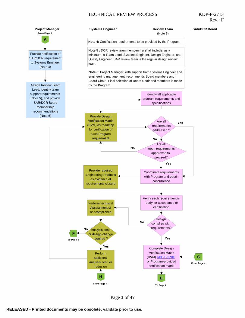
Project Manager Review Team
(Note 5)
Provide notification of
SAR/DCR requirement
to Systems Engineer
(Note 4)
Systems Engineer
Are all
requirements
addressed ?
Yes
Perform technical
Assessment of
noncompliance
Identify all applicable
program requirements and
specifications
Assign Review Team
Lead, identify team
support requirements
(Note 5), and provide
SAR/DCR Board
membership
recommendations
(Note 6)
Coordinate requirements
with Program and obtain
concurrence
Provide Design
Verification Matrix
(DVM) as roadmap
for verification of
each Program
requirement No
Analysis, test,
or design change
required ?
Verify each requirement is
ready for acceptance or
certification
Design
complies with
requirements?
No
Perform
additional
analysis, test, or
redesign
No
YesComplete Design
Verification Matrix
(DVM) KDP-F-2701,
or Program-provided
certification matrix
Yes
SAR/DCR Board
Note 4: Certification requirements to be provided by the Program.
Note 5 : DCR review team membership shall include, as a
minimum, a Team Lead, Systems Engineer, Design Engineer, and
Quality Engineer. SAR review team is the regular design review
team.
Note 6: Project Manager, with support from Systems Engineer and
engineering management, recommends Board members and
Board Chair. Final selection of Board Chair and members is made
by the Program.
Provide required
Engineering Products
as evidence of
requirements closure
From Page 1
A
To Page 4
E
H
From Page 4
G
From Page 4
F
To Page 4
Are all
open requirements
appproved to
proceed?
No
Yes
RELEASED - Printed documents may be obsolete; validate prior to use.RELEASED - Printed documents may be obsolete; validate prior to use.

TECHNICAL REVIEW PROCESS KDP-P-2713
Rev.: F
Page 4 of 47
Receipt Desk Review TeamSystems
Engineer
Provide
additional design
documentation
for SAR/DCR
and Acceptance
Data Package
Prepare and
present waiver to
appropriate
Control Board
Approve DVM, or
certification matrix,
as applicable
Waiver
approved?
Present results at
readiness review (if
required)
(Note 7)
No
Yes
Incorporate DVM and/or
signed certification report
into DCR package
Note: Certification is only
required if review type is DCR.
Assemble
SAR/DCR
package
END
SAR/DCR Board
System
complies with
requirements or
approved waiver
exists?
Sign project
certification sheet
Yes
No
Note 7: Status of a SAR/DCR should be
provided at a readiness review (if required)
and all outstanding/open/noncompliant items
should be resolved prior to acceptance.
F
From Page 3
E
From Page 3
H
To Page 3
To Page 3
G
Preside over
Board meeting
Send invitation to
participants and
make SAR/DCR
package available
Participate in
Board meeting
and record
minutes
Participate in
Board meeting
Present
SAR/DCR
package to
Board
Participate in
Board meeting
Participate in
Board meeting
Project Manager Stakeholders
RELEASED - Printed documents may be obsolete; validate prior to use.RELEASED - Printed documents may be obsolete; validate prior to use.

TECHNICAL REVIEW PROCESS Appendix A of KDP-P-2713
Rev.: F
Page 5 of 47
1. INTRODUCTION
1.1. SCOPE
This KSC Documented Procedure (KDP) describes the process for technical review of the
engineering products produced during the design and development phase. This KDP supports
the design and development portion of the project lifecycle as shown in KDP-D-1161. For more
information on Agency policy regarding Technical Reviews, reference NPR 7123.1. This
document applies to Construction of Facilities (CoF) projects when they impact non-collateral
equipment as defined in KSC-DE-512-SM, Facility Systems, Ground Support Systems, and GSE
General Design Requirements if directed, in writing, by the Technical Authority and concurred
by the funding Program customer. The references to KDP-P-2718 in this document do not apply
to CoF projects.
1.2. PURPOSE
Technical Reviews are conducted for the purpose of informing all affected organizations of the
progress of a system’s development in preparation for key decision points in the formulation and
implementation phases of the project life cycle. Technical Reviews are accomplished in
progressive steps as the system is developed to allow those affected organizations to anticipate
problems that could be avoided before the system development transitions to each subsequent
lifecycle phase. The number of Technical Reviews required will depend on the significance and
complexity of the system, or changes in requirements that affect the design of the system. Types
of technical reviews include design reviews, readiness reviews, table top reviews, Technical
Interchange Meetings (TIMs), and acceptance and certification reviews.
1.3. ROLES
The organizations responsible for each role in this KDP should be specified in the Project Plan or
SEMP as they may vary by project (with the exception of Chief Engineer which is an
Engineering Directorate responsibility). Roles to be performed by an A&E contractor, and
expected deliverables, must be included in the Design Statement of Work. Roles to be
performed by the fabricator, and expected deliverables, must be included in the Fabrication
Statement of Work or Construction Specifications used in the procurement process. For some
projects, an individual on a project may perform more than one role. This KDP is not
organizational specific. Organizational specific roles will be defined on the project’s Product
Tailoring Matrix.
Individual roles in this KDP are as follows:
a) Project Manager – The Project Manager (PM) manages the project team effort and is
responsible for delivering the certified subsystem or applicable portion of the subsystem
(CoF) and all associated products, in accordance with all technical requirements, on time and
within budget at an acceptable level of risk. Project Manager is the lead of the project that is
undergoing the review in this process. The official title may be different as set by the
different Programs/Organizations.
b) Systems Engineer – The Systems Engineer (SE) is the technical lead for the system
development and is responsible for managing the technical effort for the PM across multiple
engineering disciplines, including subsystems, and contracts. This includes ensuring quality
and effectiveness of design solutions to meet stakeholder expectations, technical
requirements and engineering products necessary to support certification or acceptance.
c) Chief Engineer – The Chief Engineer (CE) manages the technical baseline of subsystems and
RELEASED - Printed documents may be obsolete; validate prior to use.RELEASED - Printed documents may be obsolete; validate prior to use.

TECHNICAL REVIEW PROCESS Appendix A of KDP-P-2713
Rev.: F
Page 6 of 47
approves the documents outlined in KDP-P-2718, and NPR 7150.2 Compliance Matrix, if
applicable. The Chief Engineer as referenced in this document is defined as the Design and
Development Chief Engineer.
d) Design/Technical Team – The Design/Technical Team is the core group of individuals
responsible for generating the engineering products that define the system under
development. The Design/Technical Team consists of the Design Engineers (electrical,
fluids, mechanical, software, structural, architectural, civil and controls), Lead Design
Engineers (electrical, fluids, mechanical, and software), Operations Engineers (OE), and
Specialty Engineers (analysis, environmental, human factors, information technology,
operational technology, logistics, materials and processes, quality, reliability, and safety).
Design/Technical Team members are responsible for dispositioning review comments
against their respective engineering products. The A&E contractor may perform any Design
Engineer or Specialty Engineer role based on the work and deliverables specified in the
contract.
e) Contracting Officer’s Representative (COR) –The COR provides the technical
recommendation to the Contracting Officer.
f) Contracting Officer (CO) – The CO has final decision authority on all issues related to the
contract and determination of impacts to the contract.
g) Stakeholders – Stakeholders have a vested interest in the system under development, and
may include but are not limited to the Chief Engineer, Customer (outside organization
funding the project), Operations Engineer, Operations & Management organization,
Configuration Management, line management, regulatory agencies, and representatives of
interfacing systems (ground, flight, and facility). Stakeholders may or may not have
concurrence or approval authority on the engineering products (see KDP-P-2718). The
stakeholders must ensure the stakeholder expectations flow into the technical requirements
through the technical review process.
h) Receipt and Release Desk – The Receipt and Release Desk is responsible for scheduling the
review meetings, distributing review packages to the proper list of reviewers, and recording
minutes of the review meetings. The Receipt and Release Desk task may be performed by
another responsible party.
i) Technical Review Board – The review board is responsible for identifying the appropriate
review participants and verifying the contents of the review package
1.4. SUMMARY
The System Requirements Review (SRR) and Preliminary Design Review (PDR) are conducted
during the formulation phase of a project. The Critical Design Review (CDR), Test Readiness
Review (TRR), and System Acceptance Review (SAR)/Design Certification Review (DCR) are
conducted during the implementation phase of a project culminating in transition from the design
and development community to the operational community.
As determined by the Chief Engineer and Project Manager, some reviews may not be required. If
agreed to by program/project management and engineering, 30-, 60-, and 90-percent Design
Reviews will be held in place of PDR and CDR, but other formats may be used such as 45- and
90-percent Design Reviews.
Peer Reviews may be conducted at any time during system development at the discretion of the
RELEASED - Printed documents may be obsolete; validate prior to use.RELEASED - Printed documents may be obsolete; validate prior to use.

TECHNICAL REVIEW PROCESS Appendix A of KDP-P-2713
Rev.: F
Page 7 of 47
Project Manager, Systems Engineer, Chief Engineer, or Design Engineer. Software Peer Re-
views shall follow the process in KDP-P-3931.
Prior to a design review, a documented peer review of the design package shall be conducted
with individuals listed on the subsystem team roster to verify stakeholder concurrence of the
products.
Products requiring IERB approval to release, as indicated by KDP-P-2718, must be released
within 10 working days of IERB release approval.
2. TECHNICAL REVIEWS
2.1. SCHEDULE AND CONTENT
Minimum requirements for Technical Reviews shall include, but not be limited to:
a. The size and complexity of the system design shall influence the selection of organizations
required to participate in Technical Reviews. Participation by other Centers shall be
coordinated through the Program Office.
b. Other Design Reviews may be conducted as considered necessary by the responsible design
management organization:
(1) A Delta-90% Design Review (or Delta-CDR) if significant changes have been
identified at or subsequent to the 90% review (or CDR). Typically, this review would
be conducted the same as a 90% Design Review.
(2) A 45% Design Review may be conducted instead of the 30% and 60% design reviews
as agreed to by the design/technical team, project manager, and engineering
management.
(3) Peer Reviews may be conducted at any time during the design phase to present and
resolve a specific technical problem.
(4) A 90% Design Review shall be conducted for procurement of lower-level system
assemblies prior to system design completion (pre-90% drawings and/or models may
be used for bid purposes only). Technical Products for lower-level system assembly
Design Reviews shall consist of the drawings and/or models and analyses, as a
minimum (if applicable).
c. Tailoring of the required maturity of Technical Products identified in Appendix B should be
documented in the Product Tailoring Matrix (KDP-F-2713) and included in the Technical
Review package. All items in Appendix B are required unless they are tailored with
justification on the PTM. Products may be combined through tailoring. The tailoring shall be
agreed to by the Project Manager, Systems Engineer, and Design/Technical Team and
approved by the Integrated Engineering Review Board (IERB) prior to the System
Requirements Review. Products requiring IERB approval to release, as indicated by KDP-P-
2718, must be released within 10 working days of IERB release approval. Descriptions of
each Engineering Product are provided in Appendix C. Removal or tailoring of products
required by the NPR 7150.2 NASA Software Engineering Requirements must be approved
by the Software Engineering Technical Authority.
d. Contents of other or additional Design Review packages shall consist of the documentation
necessary to properly define the subject matter to be reviewed and any special data or
RELEASED - Printed documents may be obsolete; validate prior to use.RELEASED - Printed documents may be obsolete; validate prior to use.

TECHNICAL REVIEW PROCESS Appendix A of KDP-P-2713
Rev.: F
Page 8 of 47
instructions concerning problems planned for review by individuals invited to participate.
e. Appeals on results of 30-, 45-, 60-, and 90-percent Design Reviews shall be processed
through the Dissenting Opinion process defined in KSC-PLN-5400.
f. Comments to Technical Review packages shall be documented on a project approved
Comment Form or tracking tool. Comments may also be RIDs (Review Item Dispositions).
g. All Technical Reviews shall be conducted on the following minimum time allocation
schedule unless otherwise agreed to by the design/technical team, Project Manager, and
Systems Engineer:
(1) Ten working days will be allowed for the review of the data package. The cutoff date
for submitting comments will be 10 working days after receipt of the data package.
(2) A Table Top Review will be conducted as described in Section 2.7 in parallel with the
stakeholder review.
(3) Three working days will be allowed for collection and disposition of the comments
by the Design/Technical Team. The responses will be put on the original comment
form or an approved project format (e.g., Excel spreadsheet).
(4) One working day will be allowed for a review meeting to present responses to the
comments to appropriate organizations.
(5) Two working days will be allowed to submit minutes to the Project Manager for
approval.
(6) Two working days will be allowed for the Project Manager to approve minutes.
(7) Two working days will be allowed to post or distribute the approved minutes.
h. The following is typical content of a Technical Review presentation:
(1) Agenda
(2) Entrance Criteria per this KDP
(3) System description
(4) Identification of the design/technical team membership
(5) Discussion of previous review’s action items
(6) Review and discussion of assumed or approved requirements, whichever applies
(7) Design philosophy to satisfy requirements
(8) Technical data as defined in Appendix B of this KDP
(9) Review of disposition of documented comments
(10) Discussion and review of other comments or questions
(11) Resolution of any issues/problems identified
(12) Summary and documentation of decisions/actions
(13) Identification of risks
(14) Success Criteria per this KDP
RELEASED - Printed documents may be obsolete; validate prior to use.RELEASED - Printed documents may be obsolete; validate prior to use.

TECHNICAL REVIEW PROCESS Appendix A of KDP-P-2713
Rev.: F
Page 9 of 47
2.2. RESPONSIBILITIES
a. The Chair of the Technical Review Board shall perform the following functions/tasks for
each Technical Review:
(1) Determine Technical Review Board membership and provide a list of participants,
including the name and e-mail address of each participant
(2) Arrange for Receipt and Release Desk support for the Review.
(3) Ensure KSC organizations and other affected NASA and Government organizations
provide support to and participate in Technical Reviews.
(4) Establish the Technical Review schedule.
(5) Assign actions with assigned actionees and due dates.
(6) Approve resolution of actions and minutes.
(7) Schedule the Review Board meeting at KSC to review all comments, responses, and
other comments. Arrangements shall be made for a teleconference for those offsite
participants who cannot attend at the meeting site. International Traffic in Arms Reg-
ulations (ITAR) restrictions must be met when establishing communications for the
discussion of technical information.
(8) Approve the Technical Review package contents and meeting agenda.
b. The Project Manager shall be responsible for:
(1) Ensuring that Technical Reviews are conducted in compliance with NPR 7123.1 and
this KDP.
(2) Completing the entrance criteria for the review
(3) Establishing schedule dates for Technical Reviews. Schedules must be coordinated
with the customer, A&E contractor (if applicable), other support contractors, and all
affected organizations.
(4) Identifying appropriate Technical Review team members.
(5) Approving review package contents prior to distribution for review and comments.
(6) Negotiating and approving final disposition of comments.
(7) Providing funding for any A&E contract changes required due to technical comments
or other changes as a result of technical reviews.
(8) Approving minutes prior to distribution.
(9) Determining if the Technical Review meets the Success Criteria.
c. The Systems Engineer shall be responsible for:
(1) Coordinating system interfaces end-to-end.
(2) Integrating the system design with other elements of the project.
(3) Providing technical assistance, inputs, and necessary technical documents for the
review.
(4) Verifying that interfaces are identified and understood at each design review.
(5) Leading the Design/Technical Team in the review and disposition of submitted
RELEASED - Printed documents may be obsolete; validate prior to use.RELEASED - Printed documents may be obsolete; validate prior to use.

TECHNICAL REVIEW PROCESS Appendix A of KDP-P-2713
Rev.: F
Page 10 of 47
comments prior to the review meeting.
(6) Verifying Entrance Criteria for Technical Reviews, including the content and
readiness of technical review packages.
(7) Presenting the technical review package at review meetings.
(8) Conducting the screening meeting to recommend disposition of comments and
prepare the pre-Board meeting presentation.
(9) Supporting the Project Manager in the review and disposition of submitted comments
during the pre-Board meeting.
d. The Design/Technical Team shall provide support for conducting the Technical Reviews and
negotiating the disposition of comments to engineering products they generate and perform
follow-on studies and actions, as necessary. Personnel may fulfill multiple roles on the
design/technical team.
Operations Engineer: – Operations and Maintenance, training, and validation products
Design Engineers:
(1) Lead Design Engineer (CoF Design Manager) – Technical adequacy of discipline
engineering drawings, models and products
(2) Electrical Engineer – Electrical engineering drawings, models and products
(3) Fluids Engineer – Fluids engineering drawings, models and products
(4) Mechanical Engineer – Mechanical engineering drawings, models and products
(5) Software Engineer – Software design description and products
(6) Structural Engineer – Structural engineering drawings, models and products
(7) Architectural Engineer – Architectural engineering drawings, models and products
(8) Civil Engineer – Civil engineering drawings, models and products
(9) Controls Engineer – Controls engineering drawings, models and products
Specialty Engineers:
(1) Analyst – Engineering analysis/models
(2) Environmental Engineer – Environmental impacts and regulations
(3) Human Factors Engineer – Human interfaces and ergonomics
(4) Information Technology (IT)/Operational Technology (OT) Security Representative –
IT/OT security assessment/analysis
(5) Logistics Engineer – System supportability, transportation, and storage
(6) Materials and Processes Engineer – Materials and processes
(7) Quality Engineer – Quality assurance
(8) Reliability Engineer – Reliability, maintainability, and availability (RMA) analyses
(9) Safety Engineer – Safety-related analyses
e. The Contracting Officer’s Representative (COR) shall be responsible for:
RELEASED - Printed documents may be obsolete; validate prior to use.RELEASED - Printed documents may be obsolete; validate prior to use.

TECHNICAL REVIEW PROCESS Appendix A of KDP-P-2713
Rev.: F
Page 11 of 47
(1) Determining if accepted technical review comments have an impact on the A&E
contract.
(2) Providing written recommendations to the Contracting Officer to implement changes
to the A&E contract.
(3) The COR provides the technical recommendation to the Contracting Officer.
f. Contracting Officer (CO) – The CO has final decision authority on all issues related to the
contract and determination of impacts to the contract.
g. Stakeholders shall provide support for Technical Reviews relative to their area of expertise as
follows:
(1) Chief Engineer – Technical Authority for system design and development.
(2) Operations Engineer – Operations and Maintenance, Training and Validation
(3) Other Systems Engineers – Impacts to interfacing systems
(4) Configuration/Data Management Representative – Configuration/Data Management
(5) External Discipline Experts – Experts in applicable disciplines external to the
design/technical team (e.g., KSC Pressure Systems Manager)
h. The Receipt and Release Desk, or approved alternate entity shall be responsible for:
(1) Making the technical review packages available and distributing the review notice to
affected organizations.
(2) Receiving technical review comments. Comments should be submitted using a project-
approved format (e.g., Excel spreadsheet) or form KSC19-21.
(3) Consolidating comments for the Design/Technical Team to disposition prior to the
review.
(4) Preparing the invite, scheduling the review, participating in the review, capturing action
items, preparing the minutes, and distributing approved minutes.
(5) Maintaining the status of all action items throughout closeout.
(6) Performing other administrative functions, as required.
2.3. SYSTEM REQUIREMENTS REVIEW (SRR)
2.3.1. PURPOSE
The SRR examines the functional and performance requirements defined for the system and the
preliminary project plan and ensures that the requirements and the selected concept will satisfy
the mission.
2.3.2. ENTRANCE CRITERIA
a. A preliminary SRR agenda, success criteria, and charter for the review board have been
agreed to by the design/technical team, project manager, and review chair prior to the SRR.
b. SRR technical products listed in Appendix B of this KDP are reviewed for export control and
made available to the participants prior to the review.
RELEASED - Printed documents may be obsolete; validate prior to use.RELEASED - Printed documents may be obsolete; validate prior to use.

TECHNICAL REVIEW PROCESS Appendix A of KDP-P-2713
Rev.: F
Page 12 of 47
c. Lessons Learned System has been researched and applicable lessons learned have been incor-
porated into the requirements and planning. Reference KDP-KSC-P-2393.
d. Appropriate specifications and standards have been identified and incorporated into the
requirements.
2.3.3. SUCCESS CRITERIA
a. The project utilizes a sound process for the allocation and control of requirements throughout
all levels, and a plan has been defined to complete the definition activity within schedule
constraints.
b. Requirements definition is complete with respect to the identification of specifications and
standards, lessons learned, top-level program or project requirements, and interfaces with ex-
ternal entities and between major internal elements have been defined.
c. Requirements allocation and flow down of key driving requirements have been defined down
to the assembly level.
d. Preliminary approaches have been determined for how requirements will be verified and
validated (if applicable) down to the assembly level (analysis, test, demonstration, or
inspection verification method identified for each individual requirement).
e. The project risks (programmatic and technical) are understood and have been credibly
assessed, and a plan exists to effectively manage them. This plan may be at the project level
or at a higher Program level as directed by the funding customer.
2.4. 30-PERCENT DESIGN REVIEW (30%)
2.4.1. PURPOSE
The 30% Design Review demonstrates that the preliminary design meets all system requirements
with acceptable risk and within the cost and schedule constraints and establishes the basis for
proceeding with detailed design. It will show that the correct design options have been selected,
interfaces have been identified, and verification methods have been described.
2.4.2. ENTRANCE CRITERIA
a. Successful completion of the SRR and responses made to all SRR comments, or a timely
closure plan exists for those remaining open.
b. Requirements (including applicable specifications and standards) have been baselined
through the Board process. All requirements which are To Be Determined (TBD) and To Be
Resolved (TBR) must be listed and identified in the requirements database or document
c. Lessons Learned Information System has been reviewed for any applicable data that may
influence the design. Reference KDP-KSC-P-2393.
d. A 30% Design Review agenda, success criteria, and list of participants have been agreed to
by the Project Manager, Systems Engineer and Chief Engineer prior to the 30% Design
Review.
e. The technical products listed in Appendix B of this KDP for the 30% Design Review have
reached the prescribed maturity level and have been reviewed for export control, put under
configuration control (if baselined at the previous review per Appendix B), and made
available to the participants prior to the review.
RELEASED - Printed documents may be obsolete; validate prior to use.RELEASED - Printed documents may be obsolete; validate prior to use.

TECHNICAL REVIEW PROCESS Appendix A of KDP-P-2713
Rev.: F
Page 13 of 47
2.4.3. SUCCESS CRITERIA
a. The preliminary design is adequate and expected to meet the requirements.
b. The flow down of verifiable requirements is complete and proper or, if not, a plan exists for
timely resolution of open items. Requirements are traceable to program or project goals and
objectives.
c. Definition of the technical interfaces is consistent with the overall technical maturity.
d. Technical margins and associated rationale are documented.
e. Any required new technology has been developed to an adequate state of readiness, or back-
up options exist and are supported to make them a viable alternative.
f. The project risks (programmatic and technical) are understood, have been credibly assessed,
and a plan exists to effectively manage them.
g. Safety and mission assurance have been addressed in preliminary designs. This includes
safety, reliability, maintainability, availability, quality, and electrical, electronic and
electromechanical (EEE) parts
h. The operational concept is technically sound, includes (where appropriate) human factors,
and includes the flow down of requirements for its execution.
2.5. 45-PERCENT DESIGN REVIEW (45%)
2.5.1. PURPOSE
The 45% Design Review may be conducted in lieu of the 30% and 60% Design Reviews. This
review demonstrates that the preliminary design meets all system requirements with acceptable
risk and within the cost and schedule constraints and establishes the basis for proceeding with
detailed design. It will show that the correct design options have been selected, interfaces have
been identified, and verification methods have been described.
2.5.2. ENTRANCE CRITERIA
a. Successful completion of the SRR and responses made to all SRR comments, or a timely clo-
sure plan exists for those remaining open.
b. Requirements (including applicable specifications and standards) have been baselined
through the Board process. All requirements which are To Be Determined (TBD) and To Be
Resolved (TBR) must be listed and identified in the requirements database or document.
c. Lessons Learned Information System has been reviewed for any applicable data that may in-
fluence the design. Reference KDP-KSC-P-2393.
d. A 45% Design Review agenda, success criteria, and list of participants have been agreed to
by the Project Manager, Systems Engineer and Chief Engineer prior to the 45% Design Re-
view.
e. 45% Design Review technical products listed in Appendix B of this KDP have reached the
prescribed maturity level and have been reviewed for export control, put under configuration
control (if baselined at the previous review per Appendix B), and made available to the par-
ticipants prior to the review.
RELEASED - Printed documents may be obsolete; validate prior to use.RELEASED - Printed documents may be obsolete; validate prior to use.

TECHNICAL REVIEW PROCESS Appendix A of KDP-P-2713
Rev.: F
Page 14 of 47
2.5.3. SUCCESS CRITERIA
a. The preliminary design is adequate and expected to meet the requirements.
b. The flow down of verifiable requirements is complete and proper or, if not, a plan exists for
timely resolution of open items. Requirements are traceable to program or project goals and
objectives.
c. Definition of the technical interfaces is consistent with the overall technical maturity.
d. Technical margins and associated rationale are documented.
e. Any required new technology has been developed to an adequate state of readiness, or back-
up options exist and are supported to make them a viable alternative.
f. The project risks (programmatic and technical) are understood and have been credibly as-
sessed, and a plan exists to effectively manage them.
g. Safety and mission assurance have been addressed in preliminary designs. This includes
safety, reliability, maintainability, availability, quality, and electrical, electronic and electro-
mechanical (EEE) parts
h. The operational concept is technically sound, includes (where appropriate) human factors,
and includes the flow down of requirements for its execution.
2.6. 60 PERCENT DESIGN REVIEW (60%)
2.6.1. PURPOSE
The 60% Design Review demonstrates that significant progress has been made in the design
since the 30% review and that the design meets all system requirements with acceptable risk
within the cost and schedule constraints and confirms readiness to proceed with detailed design.
It will show that the design is sound, interfaces have been defined to a significant extent, and
verification methods have been confirmed.
2.6.2. ENTRANCE CRITERIA
a. Successful completion of the 30% Design Review and responses made to all 30% Design
Review comments, or a timely closure plan exists for those remaining open.
b. All requirements are defined (including applicable specifications and standards) and have
been baselined through the Board process. No TBDs exist in the released requirements and
any TBRs must be listed with at least a defined acceptable range for design.
c. Lessons Learned Information System has been reviewed for any applicable data that may
influence the design. Reference KDP-KSC-P-2393.
d. A 60% Design Review agenda, success criteria, and list of participants have been agreed to
by the Project Manager, Systems Engineer and Chief Engineer prior to the 60% Design
Review.
e. 60% Design Review technical products listed in Appendix B of this KDP for the 60% Design
Review have reached the prescribed maturity level and have been reviewed for export
control, put under configuration control (if baselined at the previous review per Appendix B),
and made available to the participants prior to the review.
RELEASED - Printed documents may be obsolete; validate prior to use.RELEASED - Printed documents may be obsolete; validate prior to use.

TECHNICAL REVIEW PROCESS Appendix A of KDP-P-2713
Rev.: F
Page 15 of 47
2.6.3. SUCCESS CRITERIA
a. All requirements have been baselined and are consistent with the current design.
b. The flow down of verifiable requirements is complete. Requirements are traceable to
program or project goals and objectives.
c. Technical interfaces are mature, consistent with the overall technical maturity.
d. Technical margins and associated rationale are documented.
e. Any required new technology has been incorporated into the design.
f. The project risks (programmatic and technical) are understood and have been credibly
assessed, and a plan exists to effectively manage them.
g. Safety and mission assurance have been addressed in the current design. This includes safety,
reliability, maintainability, availability, quality, and electrical, electronic and
electromechanical (EEE) parts.
h. The Concept of Operations has been updated as required and includes (where appropriate)
human factors and the flow down of requirements for its execution.
2.7. 90 PERCENT DESIGN REVIEW (90%)
2.7.1. PURPOSE
The 90% Design Review establishes the system design baseline and is conducted just before
committing the design to procurement. It allows all affected customers and organizations to
review the design to ensure their requirements have been satisfied.
2.7.2. ENTRANCE CRITERIA
a. Successful completion of the previous 45% or 60% Design Review and responses made to all
45% or 60% comments, or a timely closure plan exists for those remaining open.
b. All requirements are defined and have been baselined through the Board process. No TBDs
or TBRs exist in the released requirements.
c. Lessons Learned Information System has been reviewed for any applicable data that may
influence the design or fabrication/construction/procurement. Reference KDP-KSC-P-2393.
d. A 90% Design Review agenda, success criteria, and list of participants for the review have
been agreed to by the Project Manager, Systems Engineer and Chief Engineer prior to the
review.
e. The 90% technical work products listed in the Appendix B of this KDP have reached the
prescribed maturity level and have been reviewed for export control, put under configuration
control (if baselined at the previous review per Appendix B), and made available to the
participants prior to the review.
2.7.3. SUCCESS CRITERIA
a. The detailed design is expected to meet the requirements with appropriate margins shown for
design/technical team review and concurrence.
RELEASED - Printed documents may be obsolete; validate prior to use.RELEASED - Printed documents may be obsolete; validate prior to use.

TECHNICAL REVIEW PROCESS Appendix A of KDP-P-2713
Rev.: F
Page 16 of 47
b. Interface control documents (ICDs) are sufficiently matured (signed and released by affected
stakeholders) to proceed with fabrication/construction, assembly, integration, and test, and
plans are in place to manage any open items.
c. High confidence exists in the product baseline, and documentation exists or will exist in a
timely manner, to allow proceeding with fabrication/construction, assembly, integration, and
test.
d. The product verification and product validation requirements and plans are complete.
e. The verification/validation testing approach is comprehensive and the planning for system
assembly, integration, test, and launch site and mission operations is sufficient to progress
into the next phase.
f. The project risks (programmatic and technical) are understood and have been credibly
assessed, and a plan exists to effectively manage them.
g. Safety and mission assurance have been addressed in system and operational designs. This
includes safety, reliability, maintainability, availability, quality, and EEE parts.
2.8. TABLE TOP REVIEW
A Table Top Review will be conducted in parallel with the 30%, 45%, 60%, and 90% Design
Reviews, at the discretion of the Chief Engineer. The Table Top Review will be a page-by-page
review of a subset of the technical design products specified in Appendix B.
a. The participants will include the Chief Engineer(s) for the System under review, appropriate
members of the Design/Technical Team, and other key Stakeholders. The Chief Engineers,
System Project Engineer, Systems Engineer, and owners of the products to be reviewed are
required to be present at the meeting. The Chief Engineers may determine other participants
at their discretion, in coordination with the Project Manager.
b. The key products that will be reviewed at the Table Top Review will be the drawings and/or
models, design analysis, software design documents, and safety analysis. Limited hard
copies of the documentation (1 set per Chief Engineer) will be made available to the Chief
Engineers at least 2 days prior to the review.
NOTE: Following the 90% Table Top Review, the Chief Engineer will identify to the A&E
COR the critical shop drawings and/or models in the project specifications that will require
Chief Engineer review and final disposition during fabrication/construction. This will be
documented on an engineering technical concurrence form.
c. Comments from the Table Top Review will be consolidated with the Design Review
comments, tracked, and reported at the Design Review meeting.
d. The Table Top Review will be held in parallel with the 10-day external Design Review and
may require one or more days depending on the complexity of the System under review and
the number of products to be reviewed.
e. The Systems Engineer shall notify the Receipt Desk at least 10 days prior to the start of the
review in order to allow time to schedule the conference room and invite attendees. The
Systems Engineer is responsible for the following activities for the Table Top Review:
(1) Delivering hardcopies of the products to be reviewed to the Chief Engineers
(2) Determining the start and end dates of the review
RELEASED - Printed documents may be obsolete; validate prior to use.RELEASED - Printed documents may be obsolete; validate prior to use.

TECHNICAL REVIEW PROCESS Appendix A of KDP-P-2713
Rev.: F
Page 17 of 47
(3) Coordinating with the Chief Engineers and determining which Chief Engineers
should participate for their subsystem
(4) Determining who should be invited from the Design/Technical Team and
Stakeholders
(5) Setting the agenda and ensuring the right people are present at the meeting
(6) Ensuring that the authors of the products under review capture the comments and
follow-up to make sure they are documented and incorporated into the engineering
products. For CoF projects, this will be performed by the COR.
f. The author of the product for which comments are received shall be responsible for
documenting the comments and incorporating them into their engineering product.
Any engineering change during fabrication/construction and testing that affects form, fit, or
function, as determined by both the Lead Design Engineer and Systems Engineer, including
evaluation of the A&E RFIs, shall require a review with the Chief Engineers for concurrence.
This requirement does not apply to collateral facility subsystem projects. For these projects, RFI
reviews will be requested at the Design Manager’s discretion in coordination with the Chiefs.
The Systems Engineer will coordinate integrated impacts to other disciplines within the
Subsystem and other Subsystems with an interface affected by the changes.
2.9. PRELIMINARY DESIGN REVIEW (PDR)
2.9.1. PURPOSE
The PDR demonstrates that the preliminary design meets all system requirements with accepta-
ble risk and within the cost and schedule constraints and establishes the basis for proceeding with
detailed design. It will show that the correct design options have been selected, interfaces have
been identified, and verification methods have been described.
2.9.2. ENTRANCE CRITERIA
a. Successful completion of the SRR and responses made to all SRR comments and action
items, or a timely closure plan exists for those remaining open. Comments may also be
RIDs.
b. Requirements (including applicable specifications and standards) have been baselined
through the Board process. All TBDs and TBRs must be listed and identified in the require-
ments database or document.
c. Lessons Learned Information System has been reviewed for any applicable data that may in-
fluence the design.
d. A PDR agenda, success criteria, and Review Board charter have been agreed to by the de-
sign/technical team, project manager, and review chair prior to the PDR.
e. PDR technical products listed in the Appendix B of this KDP have met prescribed maturity
levels and have been reviewed for export control, put under configuration control (if base-
lined at the previous review per Appendix B) and made available to the participants prior to
the review.
2.9.3. SUCCESS CRITERIA
a. The preliminary design is adequate and expected to meet the requirements.
RELEASED - Printed documents may be obsolete; validate prior to use.RELEASED - Printed documents may be obsolete; validate prior to use.

TECHNICAL REVIEW PROCESS Appendix A of KDP-P-2713
Rev.: F
Page 18 of 47
b. The flow down of verifiable requirements is complete and proper or, if not, a plan exists for
timely resolution of open items. Requirements are traceable to program or project goals and
objectives.
c. The preliminary design is expected to meet the requirements.
d. Technical interfaces are consistent with the overall technical maturity.
e. Technical margins and associated rationale are documented.
f. Any required new technology has been developed to an adequate state of readiness, or back-
up options exist and are supported to make them a viable alternative.
g. The project risks (programmatic and technical) are understood and have been credibly as-
sessed, and a plan exists to effectively manage them.
h. Safety and mission assurance (e.g., safety, reliability, maintainability, quality, and EEE parts)
have been addressed in preliminary designs and any applicable S&MA products (e.g., Relia-
bility and Safety Assessment Report, System Assurance Analysis, etc.) have been identified.
i. The operational concept is technically sound, includes (where appropriate) human factors,
and includes the flow down of requirements for its execution.
2.10. CRITICAL DESIGN REVIEW (CDR)
2.10.1. PURPOSE
The CDR establishes the program/project design baseline. It is conducted just before committing
the design to procurement. It allows all affected customers and organizations to review the de-
sign to ensure their requirements have been satisfied.
2.10.2. ENTRANCE CRITERIA
a. Successful completion of the PDR and responses made to all PDR comments and action
items, or a timely closure plan exists for those remaining open. Comments may also be RIDs.
b. All requirements are defined and have been baselined through the Board process. No TBDs
or TBRs exist in the released requirements.
c. Lessons Learned Information System has been reviewed for any applicable data that may in-
fluence the design or fabrication/construction/procurement.
d. A CDR agenda, success criteria, and charter for the Board have been agreed to by the de-
sign/technical team, project manager, and review chair prior to the CDR.
e. CDR technical work products listed in the table in Appendix B of this KDP have met pre-
scribed maturity levels and have been reviewed for export control, put under configuration
control (if baselined at the previous review per Appendix B) and made available to the partic-
ipants prior to the review:
2.10.3. SUCCESS CRITERIA
a. The detailed design is expected to meet the requirements with appropriate margins shown
with rationale for design/technical team review and concurrence.
b. Interface control documents are sufficiently matured to proceed with procurement, fabrica-
tion/construction, assembly, integration, and test; and plans are in place to manage any open
items.
RELEASED - Printed documents may be obsolete; validate prior to use.RELEASED - Printed documents may be obsolete; validate prior to use.

TECHNICAL REVIEW PROCESS Appendix A of KDP-P-2713
Rev.: F
Page 19 of 47
c. High confidence exists in the product baseline, and documentation exists or will exist in a
timely manner to allow proceeding with fabrication/construction, assembly, integration, and
test.
d. The product verification and product validation requirements and plans are complete.
e. The testing approach is comprehensive, and the planning for system assembly, integration,
test, and launch site and mission operations is sufficient to progress into the next phase.
f. Technical margins and associated rationale are documented.
g. The project risks (programmatic and technical) are understood and have been credibly as-
sessed, and a plan exists to effectively manage them.
h. Safety and mission assurance (e.g., safety, reliability, maintainability, availability, quality,
and EEE parts) have been addressed in system and operational designs, and any applicable
S&MA products (e.g., Reliability and Safety Assessment Report, System Assurance Analy-
sis, etc.) have been approved.
2.11. TEST READINESS REVIEW (TRR)
2.11.1. PURPOSE
A Test Readiness Review (TRR) ensures that the article under test (hardware/software), test
facility, support personnel, and test procedures are ready for testing and data acquisition,
reduction, and control.
2.11.2. ENTRANCE CRITERIA
a. All previous design review success criteria have been met and key issues resolved.
b. The objectives of the testing have been clearly defined and documented and all of the test
plans, procedures, environment, and configuration of the test item(s) support those
objectives.
c. Configuration of the system under test has been defined, agreed to, and all interfaces have
been placed under configuration management or have been defined in accordance with an
agreed-to plan.
d. All applicable functional, unit-level, subsystem, system, and qualification testing has been
conducted successfully.
e. TRR technical products listed in the table in Appendix B of this KDP have reached the
designated level of maturity and been reviewed for export control, put under configuration
control if baselined per Appendix B, and made available to the participants prior to the
review.
f. Lessons Learned Information System has been reviewed for any applicable data that may
influence the testing. Reference KDP-KSC-P-2393.
g. All known system discrepancies have been identified and resolved.
h. All required test resources: properly trained and certified people (including a designated test
director), facilities, test articles, test instrumentation, and other test enabling products have
been identified and are available to support required tests.
i. Roles and responsibilities of all test participants are defined and agreed to.
RELEASED - Printed documents may be obsolete; validate prior to use.RELEASED - Printed documents may be obsolete; validate prior to use.

TECHNICAL REVIEW PROCESS Appendix A of KDP-P-2713
Rev.: F
Page 20 of 47
j. Test contingency planning has been accomplished and all personnel have been trained.
k. Processes exist for documenting, troubleshooting, and resolving discrepancies during the test
and for procedural or test-case changes involving verification of requirements or interfaces as
a result.
l. Safety procedures are in place that define emergency response procedures. Appropriate
emergency response organizations have been notified and personnel have been briefed on the
procedures.
m. Warning limits have been established for test parameters and written instructions exist for
each warning alarm.
n. Redline limits for stopping test operations have been identified with written instructions on
how to safe the article under test and the test equipment.
2.11.3. SUCCESS CRITERIA
a. Test plans are completed and approved for the system under test.
b. Identification and coordination of required test resources are completed.
c. Previous component, subsystem, and system test results form a satisfactory basis for
proceeding into planned tests.
d. Risk level is identified and accepted by program/competency leadership as required.
e. Plans to capture any lessons learned from the test program are documented.
f. The objectives of the testing have been clearly defined and documented, and the review of all
test plans (as well as the procedures, environment, and configuration of the test item) provide
a reasonable expectation that the objectives will be met.
g. The test cases have been reviewed and analyzed for expected results and the results are
consistent with the test plans and objectives.
h. Test and test support personnel are properly trained and certified in their subject area and
have received appropriate training in test operation and safety procedures including
emergency response.
2.12. SYSTEM ACCEPTANCE REVIEW (SAR)
2.12.1. PURPOSE
The System Acceptance Review (SAR) verifies the completeness of the specific end item
products in relation to their expected maturity level for turnover from the development phase
owner to the operational phase owner and assesses compliance to stakeholder expectations. The
SAR examines the system, its end items and documentation, test data, and analyses that support
verification. It also ensures that the system has sufficient technical maturity to authorize
transition to the operational organization and its shipment to the designated operational facility
or launch site. A Design Certification Review (DCR) may be conducted in lieu of the SAR when
agreed to by the project management and engineering.
RELEASED - Printed documents may be obsolete; validate prior to use.RELEASED - Printed documents may be obsolete; validate prior to use.

TECHNICAL REVIEW PROCESS Appendix A of KDP-P-2713
Rev.: F
Page 21 of 47
2.12.2. ENTRANCE CRITERIA
a. All verification and validation testing has been successfully completed and all open issues
have been resolved or a timely closure plan exists for those remaining open. For CoF,
validation may be completed by other entities after turnover and SAR completion.
b. A preliminary agenda has been coordinated prior to the SAR.
c. SAR technical products listed in the table in Appendix B of this KDP have met prescribed
maturity levels and have been reviewed for export control, put under configuration control (if
baselined following the previous review per Appendix B), and made available to the
participants prior to the review.
d. Lessons learned have been submitted to the Lessons Learned Information System. Reference
KDP-KSC-P-2393.
e. Any audits or assessments required by the Quality Assurance Plan or organizational
assessment plan (e.g., CMMI Appraisal) have been performed and all findings and
observations have been resolved, or a timely closure plan exists for those remaining open.
2.12.3. SUCCESS CRITERIA
a. Required tests and analyses are complete and indicate that the system will perform properly
in all expected operational environments.
b. Risks are quantified, documented, and agreed to by the customer.
c. System meets the established acceptance criteria as documented in the Design Verification
Matrix.
d. Required shipping, handling, checkout, and operational plans are complete.
e. The Acceptance Data Package (ADP) is complete and reflects the delivered system.
f. All applicable lessons learned for organizational improvement and system operations are
entered in the Lessons Learned Information System.
2.13. DESIGN CERTIFICATION REVIEW (DCR)
2.13.1. GENERAL PROVISIONS
a. If one or more of the following criteria are met, the Project Manager, in conjunction with
program representatives and the Chief Engineer, may decide that a Design Certification
Review (DCR) is required:
Affects Launch Commit Criteria
Adds or eliminates a single failure point
Implements a new system with a single failure point
Represents a significant modification to an existing certified system
Affects systems baselined in the customer’s master verification plan
Affects systems/facilities that provide protection of flight hardware
Interfaces directly with flight hardware
RELEASED - Printed documents may be obsolete; validate prior to use.RELEASED - Printed documents may be obsolete; validate prior to use.

TECHNICAL REVIEW PROCESS Appendix A of KDP-P-2713
Rev.: F
Page 22 of 47
b. The DCR evaluates the engineering documentation to ensure that the system has been
verified to meet all program requirements, validated to meet all stakeholder expectations, and
that traceability exists to the evidence supporting certification. DCRs shall be conducted
prior to system turnover to support flight hardware processing or readiness reviews for
designated activities (e.g., return-to-flight). DCRs may also be conducted for major design
changes as determined by the Project Manager.
c. The DCR is a detailed technical review conducted in a series of meetings by the DCR
Review Team (reference KTI-2713C) of the engineering products and data to certify the
system meets all requirements, culminating in a presentation of the final results to the DCR
Board.
d. The following program/project design requirements shall be reviewed during the DCR:
(1) Program/project requirements and stakeholder expectation documents
(2) Interface Control Documents (ICDs)
(3) Design requirements, as applicable, (e.g., KSC-DE-512-SM, NASA-STD-5005)
(4) Operations and Maintenance Requirements and Specifications (OMRS).
e. The following system design documents shall be reviewed for conformance to
program/project requirements:
(1) Drawings and/or models and specifications
(2) Design criteria/requirements documents
(3) Design Verification Matrix.
(4) Analysis documents (DAR, RSAR, LSA, RMA, etc.)
(5) Operations and Maintenance Requirements Specification Documents (OMRSD)
(6) Test requirements documents and test reports (if applicable)
(7) Analyses (if applicable)
(8) Acceptance Data Packages (ADPs)
2.13.2. RESPONSIBILITIES
a. The Project Manager shall have the primary responsibility for the orderly and timely
completion of the DCR, in accordance with this KDP. Specifically, the Project Manager
shall perform the following tasks:
(1) Determine if a DCR is required, in conjunction with the Chief Engineer and Program
Management.
(2) Designate a DCR Team lead.
(3) Provide DCR Team resources.
(4) Provide DCR notification to DCR Board Chair.
(5) Recommend DCR Board membership.
(6) Conduct the DCR pre-Board meeting.
(7) Release the results of the DCR through KSC Design Data Management System
(KDDMS) (in accordance with KDP-P-2718) or through other appropriate means.
RELEASED - Printed documents may be obsolete; validate prior to use.RELEASED - Printed documents may be obsolete; validate prior to use.

TECHNICAL REVIEW PROCESS Appendix A of KDP-P-2713
Rev.: F
Page 23 of 47
b. The DCR Review Team shall perform the following tasks (reference KTI-2713C):
(1) Identify applicable program requirements, specifications, and stakeholder
expectations.
(2) Coordinate requirements with program and obtain concurrence.
(3) Certify verification of each requirement and validation of each stakeholder
expectation.
(4) Prepare and submit Design Verification Matrix (DVM), KDP-F-2701 or program-
provided certification matrix.
(5) Assemble DCR package (include DVM, or program-provided certification matrix).
(6) Sign project certification sheet (select members) after successful completion of the
DCR review prior to the DCR Board.
c. The Systems Engineer (with support from the Design/Technical Team) shall perform the
following tasks:
(1) Serve as the lead of the DCR Review Team.
(2) Provide data in support of the project DCR and provide support to the DCR Board.
(3) Review the design for conformance with applicable program requirements.
(4) Certify that the design satisfies all program/project design requirements.
(5) Provide the status of the certification progress on the system, when requested.
(6) Conduct the screening meeting prior to the DCR pre-Board meeting.
(7) Obtain signatures on the DCR certificate after successful completion of all DCR
Review Team activities.
(8) Present the results of the DCR Review Team to the DCR Board.
(9) Initiate redesign activities (if required).
(10) Prepare waivers and present to appropriate control board (if required).
(11) Present DCR results at program readiness reviews (if required).
d. The DCR Board shall perform the following tasks:
(1) Review the DCR package and determine whether the system complies with
applicable program requirements.
(2) Accept DCR Review Team certification of the system or define open work to be
completed before accepting certification.
(3) Track all open work identified at the DCR to closure.
2.13.3. CONTENTS OF DCR PRESENTATION
Items presented should reflect the Product Tailoring Matrix and may include:
DCR Purpose and Authority
DCR Review Team
Design Certification Process
RELEASED - Printed documents may be obsolete; validate prior to use.RELEASED - Printed documents may be obsolete; validate prior to use.

TECHNICAL REVIEW PROCESS Appendix A of KDP-P-2713
Rev.: F
Page 24 of 47
Entrance Criteria
System History
System Description/Overview
Design Verification Matrix
Interface Control Documentation
Design Analysis Summary
Verification and Validation Testing Summary
Safety & Mission Assurance Summary
Human Factors Engineering Assessment Summary
Logistics Supportability Analysis Summary
Configuration Status
Operations and Maintenance (O&M) Documentation Status
Deviations/Waivers
Open Work/Issues
Forward Work
Success Criteria
Statement of Certification
Recommendation
Backup Charts
2.13.4. ENTRANCE CRITERIA
a. All verification and validation testing has been successfully completed and all open issues
have been resolved or a timely closure plan exists for those remaining open.
b. A preliminary agenda has been coordinated prior to the DCR.
c. DCR engineering products listed in the table in Appendix B of this KDP have met prescribed
maturity levels and have been reviewed for export control, put under configuration control (if
baselined following the previous review per Appendix B), and reviewed by the DCR Review
Team prior to the DCR Board meeting (reference KTI-2713C).
d. Lessons learned have been submitted to the Lessons Learned Information System. Reference
KDP-KSC-P-2393.
e. Any audits or assessments required by the Quality Assurance Plan or organizational
assessment plan (e.g., CMMI Appraisal) have been performed and all findings and
observations have been resolved, or a timely closure plan exists for those remaining open.
2.13.5. SUCCESS CRITERIA
a. Required tests and analyses are complete and indicate that the system meets all design
requirements.
RELEASED - Printed documents may be obsolete; validate prior to use.RELEASED - Printed documents may be obsolete; validate prior to use.

TECHNICAL REVIEW PROCESS Appendix A of KDP-P-2713
Rev.: F
Page 25 of 47
b. Risks are known and manageable.
c. Certification of the system by the DCR Review Team is complete and approved by the DCR
Board.
d. Required shipping, handling, checkout, and operational plans are complete.
e. The Acceptance Data Package (ADP) is complete and reflects the delivered system.
f. All applicable lessons learned for organizational improvement and system operations are
entered into the Lessons Learned Information System. Reference KDP-KSC-P-2393.
RELEASED - Printed documents may be obsolete; validate prior to use.RELEASED - Printed documents may be obsolete; validate prior to use.

ENGINEERING PRODUCTS Appendix B of KDP-P-2713
Rev.: F
Page 26 of 47
Pro
du
ct I
D
Product Title
Product Attributes Technical Reviews
SRR
AN
D
OR
AN
D
TRR
SAR
or
DCR Owner Author 30% 60%
OR
45%
AN
D
90% PDR CDR
1 Team Roster1 PM PM P U U U U U U U U
2 Stakeholder Expectations1 SE OE B F F F
3 Concept of Operations (ConOps) SE OE B U U U F U F
4 System Requirements SE SE F
5 Design Verification Matrix SE SE B U U U U U U U F
6 Product Tailoring Matrix PM SE B U U U U U U U F
7 Design Statement of Work PM SE/LDE F
8 Cost Estimate2 PM PM B U U U U U U U U
9 Schedule1 PM PM B U U U U U U U U
10 Project Plan PM PM B F F F
11 Systems Engineering Management Plan (SEMP) SE SE B F F F
12 Risk Management Plan (RMP) PM PM B F F F
13 Configuration Management Plan (CMP) SE SE B F F F
14 Quality Assurance Plan (QAP) PM SPE B F F F
15 Acquisition Plan PM PM B F F F
16 Logistics Support Analysis Development Plan SPE SPE B U U U F U F
17 Software Assurance Classification Assessment (SACA)
Report SE SPE NA
F
F F
18 Software Development/Management Plan (SDP/SMP) and
NPR 7150.2 Compliance Matrix SE SPE B
F
F F
19 Software Assurance Plan SE SPE B F F F
20 Software Safety Plan SE SPE B F F F
21 Software Test Plan SE DE NA P B B F B F
22 Trade Study Plan/Report SE DE NA B U B F B F
23 Product Structure/Indentured System Documentation List SE LDE NA B U B U B U U F
24 Risk Matrix PM SE NA P U U U U U U U
25 Lessons Learned Plan/Report SE SE NA P U P U P U U F
26 Prototype Plan/Report LDE DE NA B U B F B F
27 Interface Control Document (ICD) 1 SE SE NA B U B F B F
28 Interface Table3 SE SE NA P B B F B F
29 Reliability and Safety Assessment Report (RSAR) SE SPE NA P U P F P F
30 IT/OT Security Assessment SE SPE NA NA P P F P F
31 System Assurance Analysis (SAA) SE SPE NA P U P B P B U F
32 Software Safety Analysis (SSA) SE SPE NA P U P B P B U F
33 Environmental Checklist2 SE SE NA P U P U P U U U
34 Human Factors Engineering Assessment SPE SPE NA P U P B P B U F
34.1 Human-in-the-Loop Evaluation SPE SPE NA P U P B P B U F
34.2 Human Error Analysis SPE SPE NA P U P B P B U F
34.3 Workload Assessment SPE SPE NA P U P B P B U F
35 Verification Plan SE DE NA P U P B P B F
36 Validation Plan SE OE NA P U P B P B F
37 Integration Plan SE SE NA P U P B P B U F
RELEASED - Printed documents may be obsolete; validate prior to use.RELEASED - Printed documents may be obsolete; validate prior to use.
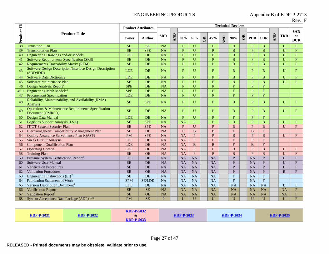
ENGINEERING PRODUCTS Appendix B of KDP-P-2713
Rev.: F
Page 27 of 47
Pro
du
ct I
D
Product Title
Product Attributes Technical Reviews
SRR
AN
D
OR
AN
D
TRR
SAR
or
DCR Owner Author 30% 60%
OR
45%
AN
D
90% PDR CDR
38 Transition Plan SE SE NA P U P B P B U F
39 Transportation Plan SE SPE NA P U P B P B U F
40 Engineering Drawings and/or Models LDE DE NA P U P B P B U F
41 Software Requirements Specification (SRS) SE DE NA P U P B P B U F
42 Requirements Traceability Matrix (RTM) SE DE NA P U P B P B U F
43 Software Design Description/Interface Design Description
(SDD/IDD) LDE DE NA
P U
P B P B U F
44 Software Data Dictionary LDE DE NA P U P B P B U F
45 Software Maintenance Plan SE DE NA P U P B P B U F
46 Design Analysis Report4 SPE DE NA P U P F P F
46.1 Engineering Math Models4 SPE DE NA P U P F P F
47 Procurement Specification LDE DE NA P U P F P F
48 Reliability, Maintainability, and Availability (RMA)
Analysis SE SPE NA
P U P B P B U F
49 Operations & Maintenance Requirements Specification
Document (OMRSD) SE DE NA
P U
P B P B U F
50 Design Data Manual LDE DE NA P U P F P F
51 Logistics Support Analysis (LSA) SE SPE NA NA P P B P B U F
52 IT/OT System Security Plan SE SPE NA P U P B P B U F
53 Electromagnetic Compatibility Management Plan SE DE NA P B B F B F
54 Quality Assurance Surveillance Plan (QASP) PM SPE NA NA P P B P B U F
55 Sneak Circuit Analysis LDE DE NA NA P P F P F
56 Component Qualification Plan LDE DE NA NA B B F B F
57 Operating Criteria LDE DE NA NA P P B P B U F
58 Training Plan SE OE NA NA P P B P B U F
59 Pressure System Certification Report1 LDE DE NA NA NA NA P NA P U F
60 Software User Manual SE DE NA NA NA NA P NA P U F
61 Verification Procedures SE DE NA NA NA NA P NA P B F
62 Validation Procedures SE OE NA NA NA NA P NA P B F
63 Engineering Instructions (EI) 2 SE DE NA NA NA NA F NA F
64 Fabrication Statement of Work SPM SE/LDE NA NA NA NA F NA F
65 Version Description Document1 LDE DE NA NA NA NA NA NA NA B F
66 Verification Report1 SE SE NA NA NA NA NA NA NA NA F
67 Validation Report1 SE OE NA NA NA NA NA NA NA NA F
68 System Acceptance Data Package (ADP) 1 2 5 PM SE P U U U U U U U F
KDP-P-5031 KDP-P-5032
KDP-P-5032
&
KDP-P-5033
KDP-P-5033 KDP-P-5034 KDP-P-5035
RELEASED - Printed documents may be obsolete; validate prior to use.RELEASED - Printed documents may be obsolete; validate prior to use.

ENGINEERING PRODUCTS Appendix B of KDP-P-2713
Rev.: F
Page 28 of 47
Footnotes
1 Product is not subject to comment during reviews 2 Product is not included in reviews
3
The Interface Tables for interfacing systems shall also be provided
in the review package as reference, but are not subject to comment
during the review. Comments to Interface Tables for these interfac-
ing systems must be made during that system’s review. 4 Product may be delegated to a Design Engineer
5
The system ADP is composed of all the engineering data generated
during system development. Vendor ADPs for procured items are a
subset of the system ADP and may be available for subassem-
blies/components prior to SAR/DCR. (Reference KDP-P-5042)
Product Attributes Owner/Author
PM Project Manager SE Systems Engineer
DE Design Engineer (electrical, fluids, mechanical, software, structural,
architectural, civil and controls). May be performed by A&E per
SOW LDE Lead Design Engineer OE Operations Engineer
SPE Specialty Engineer (analysis, environmental, human factors, infor-
mation technology, operational technology, logistics, materials and
processes, quality, reliability, safety, pressure systems manager) The roles are not organizational specific. Organizational specific roles
will be defined on the project’s PTM. Product ID numbers and the PTM product organization above may not
reflect the folder structure in KDDMS.
Product Maturity
P Preliminary An initial version of the product which provides an
overview of how the subject matter will be addressed
and incorporated into the design.
B Baselined
An approved version of the product against which
changes may be assessed and tracked. The product is
baselined following incorporation of comments from
the indicated technical review and released.
U Updated
The latest version of the product based on the existing
maturity and level of detail in the design at the time of
the indicated technical review. If previously base-
lined, the product should be revised and re-released
following the technical review after incorporating any
comments accepted during the technical review.
F Final
The final version of the product which requires no
more updates before transition to Operations. The
product is finalized by incorporating comments from
the indicated technical review and released. NOTE:
This is the expected Final version, but the product may
be updated during subsequent phases.
RELEASED - Printed documents may be obsolete; validate prior to use.RELEASED - Printed documents may be obsolete; validate prior to use.
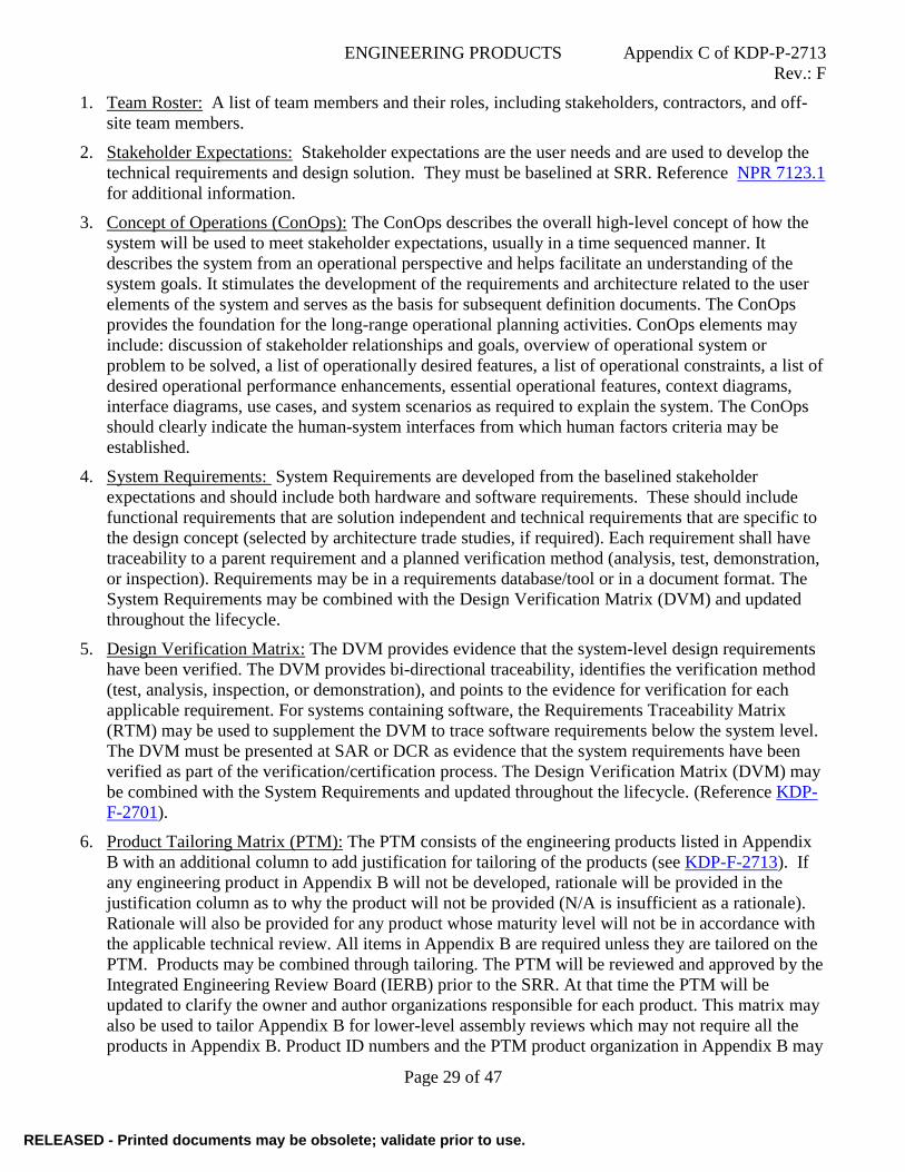
ENGINEERING PRODUCTS Appendix C of KDP-P-2713
Rev.: F
Page 29 of 47
1. Team Roster: A list of team members and their roles, including stakeholders, contractors, and off-
site team members.
2. Stakeholder Expectations: Stakeholder expectations are the user needs and are used to develop the
technical requirements and design solution. They must be baselined at SRR. Reference NPR 7123.1
for additional information.
3. Concept of Operations (ConOps): The ConOps describes the overall high-level concept of how the
system will be used to meet stakeholder expectations, usually in a time sequenced manner. It
describes the system from an operational perspective and helps facilitate an understanding of the
system goals. It stimulates the development of the requirements and architecture related to the user
elements of the system and serves as the basis for subsequent definition documents. The ConOps
provides the foundation for the long-range operational planning activities. ConOps elements may
include: discussion of stakeholder relationships and goals, overview of operational system or
problem to be solved, a list of operationally desired features, a list of operational constraints, a list of
desired operational performance enhancements, essential operational features, context diagrams,
interface diagrams, use cases, and system scenarios as required to explain the system. The ConOps
should clearly indicate the human-system interfaces from which human factors criteria may be
established.
4. System Requirements: System Requirements are developed from the baselined stakeholder
expectations and should include both hardware and software requirements. These should include
functional requirements that are solution independent and technical requirements that are specific to
the design concept (selected by architecture trade studies, if required). Each requirement shall have
traceability to a parent requirement and a planned verification method (analysis, test, demonstration,
or inspection). Requirements may be in a requirements database/tool or in a document format. The
System Requirements may be combined with the Design Verification Matrix (DVM) and updated
throughout the lifecycle.
5. Design Verification Matrix: The DVM provides evidence that the system-level design requirements
have been verified. The DVM provides bi-directional traceability, identifies the verification method
(test, analysis, inspection, or demonstration), and points to the evidence for verification for each
applicable requirement. For systems containing software, the Requirements Traceability Matrix
(RTM) may be used to supplement the DVM to trace software requirements below the system level.
The DVM must be presented at SAR or DCR as evidence that the system requirements have been
verified as part of the verification/certification process. The Design Verification Matrix (DVM) may
be combined with the System Requirements and updated throughout the lifecycle. (Reference KDP-
F-2701).
6. Product Tailoring Matrix (PTM): The PTM consists of the engineering products listed in Appendix
B with an additional column to add justification for tailoring of the products (see KDP-F-2713). If
any engineering product in Appendix B will not be developed, rationale will be provided in the
justification column as to why the product will not be provided (N/A is insufficient as a rationale).
Rationale will also be provided for any product whose maturity level will not be in accordance with
the applicable technical review. All items in Appendix B are required unless they are tailored on the
PTM. Products may be combined through tailoring. The PTM will be reviewed and approved by the
Integrated Engineering Review Board (IERB) prior to the SRR. At that time the PTM will be
updated to clarify the owner and author organizations responsible for each product. This matrix may
also be used to tailor Appendix B for lower-level assembly reviews which may not require all the
products in Appendix B. Product ID numbers and the PTM product organization in Appendix B may
RELEASED - Printed documents may be obsolete; validate prior to use.RELEASED - Printed documents may be obsolete; validate prior to use.

ENGINEERING PRODUCTS Appendix C of KDP-P-2713
Rev.: F
Page 30 of 47
not reflect the folder structure in KDDMS.
7. Design Statement of Work (SOW): The design SOW is a contracting document which defines the
design work to be performed, period of performance, deliverable schedule, applicable performance
standards, schedule for planned design reviews, type of contract/payment schedule, and any special
requirements (e.g., security clearances, travel, special knowledge). The design SOW should be
performance-based to the maximum extent practical. Reference NASA Federal Acquisition
Regulations (FAR) Supplement.
8. Cost Estimate: The Cost Estimate identifies the costs associated with system development from the
Concept Development phase through the SAR/DCR, to include any development spares
(verification/validation, burn-in, etc.). The cost estimate should break out procurement costs as well
as FTE (NASA personnel) and WYE (contractor personnel) support phased over the development
life of the system. These costs should be broken out by the Work Breakdown Structure (WBS)
defining the system. The level of detail should be sufficient to enable Earned Value Management
(EVM), if required. The Cost Estimate should show phasing by Fiscal Year for both Obligations and
Costs. Reference the NASA Cost Estimating Handbook for more information. The cost estimate is
required for management of the project effort but is not to be included in the Technical Review
package.
9. Schedule: The Schedule defines all activities required to support system development from project
start through the SAR/DCR. The schedule identifies design activities associated with the system be-
ing developed and significant activities required for design review products. The schedule should
contain fabrication/construction and testing activities. Interdependencies with other system schedule
milestones should be included. The schedule should consider constraints from stakeholders and other
systems/subsystems. More detailed schedules for system development may be maintained for spe-
cific design engineering activities by supporting organizations but are not reportable or reviewable
unless desired by the project management organization. Reference NASA/SP-2010-3403 for more
information on schedule management. The schedule in not subject to comments during the Technical
Review.
10. Project Plan: The Project Plan is a document used to guide both project execution and project
control. The Project Plan documents planning assumptions and decisions, facilitates communication
among stakeholders, and documents scope, cost, and schedule baselines. Reference NPR 7120.5 for
more information on the project plan for Space Flight projects.
11. Systems Engineering Management Plan (SEMP): The SEMP identifies the roles and responsibility
interfaces of the technical effort and how those interfaces will be managed. The SEMP is the vehicle
that documents and communicates the technical approach, including the application of the common
technical processes; resources to be used; and key technical tasks, activities, and events along with
their metrics and success criteria. If a system is covered in sufficient detail by a higher-level SEMP
in the program/project architecture or in the Project Plan, a stand-alone SEMP is not required.
Reference NPR 7123.1 for more information on the SEMP.
12. Risk Management Plan (RMP): The RMP summarizes how the NASA risk management process will
be implemented in accordance with NPR 8000.4 including risk-informed decision making (RIDM)
and continuous risk management (CRM) as applicable. The risk management plan may be either a
stand-alone document or a component of the Project Plan or SEMP. If a system is covered in
sufficient detail by a higher-level RMP in the program/project architecture, a stand-alone RMP is not
required. See NASA/SP-2010-576 for more information on RIDM and CRM.
RELEASED - Printed documents may be obsolete; validate prior to use.RELEASED - Printed documents may be obsolete; validate prior to use.

ENGINEERING PRODUCTS Appendix C of KDP-P-2713
Rev.: F
Page 31 of 47
13. Configuration Management Plan (CMP): The CMP should describe the overall configuration
management approach that the design/technical team will implement, including software. The plan
should describe the structure of the CM organization and any CM tools to be used. The plan should
define the methods and procedures to be used for configuration identification, configuration control,
interface management, configuration traceability, and configuration status accounting to meet the
requirements of SAE/EIA 649-2. The CMP may be either a stand-alone document or a component of
the Project Plan or SEMP. If a system is covered in sufficient detail by a higher-level CMP in the
program/project architecture, a stand-alone CMP is not required. Reference NPR 7123.1 and NPR
7150.2 for more information on the CMP.
14. Quality Assurance Plan (QAP): The QAP defines how quality assurance activities will be
implemented during the design, development, fabrication/construction, and testing phases for a given
system. The QAP should identify the Quality Assurance Surveillance Plan (QASP) that will be
necessary for procurement activities. It should also define how quality assurance activities will be
performed during installation and testing (including engineering modifications as a result thereof)
prior to turnover. The QAP may be either a stand-alone document or a component of the Project Plan
or SEMP. If a system is covered in sufficient detail by a higher-level QAP in the program/project
architecture, a stand-alone QAP is not required.
15. Acquisition Plan: The Acquisition Plan should contain the following items:
Long Lead Procurement Item List – This list documents all procurement items that need to be
ordered before completion of the CDR or 90% Design Review in order to meet the
development schedule. The list should include the manufacturer's part number for each item, a
brief description of the item, an estimated cost per unit, the quantity required to be ordered in
advance, and an estimated delivery time from when the order is placed.
Major Item Procurement List – This list identifies all items that need to be procured as a part of
system development that have an estimated cost of more than $500K. The list includes the
manufacturer's part number, item description, estimated item cost, and quantity required.
Make/Buy Decisions – Each make/buy decision is documented with a short description of
content, rationale for make vs. buy, and cost of the chosen approach.
If a system is covered in sufficient detail by a higher-level Acquisition Plan in the program/project
architecture, a stand-alone Acquisition Plan is not required. The Acquisition Plan may be either a
stand-alone document or a component of the Project Plan. Acquisition planning shall meet the
requirements of NASA Federal Acquisition Regulations (FAR) Supplement (NFS), Part 1807.
16. Logistics Support Analysis Development Plan: This plan specifies LSA products and data to be de-
veloped, assigns organizational responsibilities and establishes delivery dates.
17. Software Assurance Classification Assessment (SACA) Report: The SACA Report identifies and
evaluates the characteristics of software in determining the software’s classification as defined in
NPR 7150.2. The resultant classification (Class A through E for engineering software) will deter-
mine the level of software assurance to be applied during development of the software. SACA Re-
ports are performed in accordance with NASA-STD-8739.8 using KDP-KSC-F-3631. The software
classification is initially determined by the Design Engineer and then a SACA report is generated
independently by a Safety and Mission Assurance (S&MA) representative who then reconciles the
two into a single assessment. If a system is covered in sufficient detail by a higher-level SACA in
the program/project architecture, a stand-alone SACA is not required.
RELEASED - Printed documents may be obsolete; validate prior to use.RELEASED - Printed documents may be obsolete; validate prior to use.

ENGINEERING PRODUCTS Appendix C of KDP-P-2713
Rev.: F
Page 32 of 47
18. Software Development Plan/Software Management Plan (SDP/SMP) and NPR 7150.2 Compliance
Matrix: The SDP/SMP provides insight into, and a tool for monitoring, the processes to be followed
for software development activities, including the method and approach to be followed for each
activity. This plan details the project planning and monitoring activities, project documentation,
project schedules, organizational structure, resource requirements and constraints, metrics collection,
risk management, etc. Projects may use either a single SDP or SMP, or they may use both types of
documents (with different scope and/or focus) as needed to cover all aspects of the project. A
compliance matrix for NPR 7150.2 requirements shall be provided as an Appendix in the SDP/SMP,
or as a stand-alone document. Approval of the NPR 7150.2 Compliance Matrix by the Software
Engineering Technical Authority is required, whether it be stand-alone or in the SDP/SMP.
Reference KNPR 7150.2, KSC Software Engineering Requirements and KDP-T-
7150.2_EPG_SDP_SMP template for more information on the SDP/SMP and associated compliance
matrix.
19. Software Assurance Plan (SAP): The SAP provides the details on the plans, roles and
responsibilities associated with software assurance. The plan can be combined with the SDP/SMP
but the independent software assurance organizer must sign off on the plan. Reference NPR 7150.2
and NASA-STD-8739.8 for additional details. If a system is covered in sufficient detail by a higher-
level SAP in the program/project architecture, a stand-alone SAP is not required.
20. Software Safety Plan (SSP): The SSP is required when a project contains software identified as
safety critical and the requirements of NASA-STD-8719.13 must be implemented. The Software
Safety Plan outlines the software safety process, including organizational structure, interfaces, and the
required criteria for analysis, reporting, evaluation, and data retention to provide a safe product. The plan
describes forms of analysis and provides a schedule for performing a series of analyses throughout the
development cycle. It also addresses how the results of software safety analyses and the sign-off and
approval process should be handled. This plan provides the foundation for all future software safety
activities. The SSP may be a separate document or included within other documents, such as the
SDP/SMP. Reference NPR 7150.2 and NASA-GB-8719.13 for additional details.
21. Software Test Plan (STP): The STP ensures the appropriate planning for all test activities are
considered. It provides insight into the types and levels of testing, how testing will be handled from
an activity perspective, recording of data, analysis of data and traceability of requirements. The STP
plan can be a stand-alone document or part of the SDP/SMP. Reference NPR 7150.2 for additional
details. If a system is covered in sufficient detail by a higher-level STP in the program/project
architecture, a stand-alone STP is not required.
22. Trade Study Plan/Report: The Trade Study Plan/Report is a document that initially defines the plan
for performing trade studies on the system and later summarizes the results of the trade studies
conducted during the definition of the system. The document should include a summary of the
structured decision analysis, including selection criteria, used to conduct the trade studies.
23. Product Structure/Indentured System Documentation List: The Product Structure represents the
physical assemblies, component parts, and standard parts that go into the design and manufacturing
of the Product. In a Product Lifecycle Management (PLM) system such as Windchill, Product Struc-
ture consists of the objects that represent the actual physical parts that are designed, purchased, and
manufactured, as well as the services for the Products that are to be delivered to the customer. Spe-
cifically, the organization of the objects within the Product Structure are defined according to hierar-
chical and other relationship requirements. If a PLM system is not used during design and develop-
ment, an Indentured System Documentation List will serve as an alternate method to represent the
system’s physical structure and associated documentation.
RELEASED - Printed documents may be obsolete; validate prior to use.RELEASED - Printed documents may be obsolete; validate prior to use.

ENGINEERING PRODUCTS Appendix C of KDP-P-2713
Rev.: F
Page 33 of 47
24. Risk Matrix: The Risk Matrix documents system-specific technical risks that exist as a result of the
system requirements, allocated cost and schedule, and other imposed constraints. The identification
of a risk should include the undesirable event the risk presents as well as the consequences if that
event occurs. Risks shall be reviewed by the Integrated Engineering Review Board (IERB) to
determine if they should be elevated to the Program.
25. Lessons Learned Plan/Report: The Lessons Learned Plan/Report documents how Lessons Learned
found in the NASA Lessons Learned Information System (LLIS), historical information, and/or
consultation with experts are applied during the design and development of a system as well as how
Lessons Learned gathered during the design and development process are added into the LLIS for
the benefit of future development efforts. Refer to NASA/SP-2016-6105 for more information on
how to apply Lessons Learned.
26. Prototype Plan/Report: The Prototype Plan/Report is a document that initially defines the plan for
the prototyping effort and later includes the report of the results of the prototyping effort.
27. Interface Control Document (ICD): The ICD depicts physical and functional interface engineering
requirements between systems and is used as a design control document that delineates interface
engineering data for the purpose of: (1) establishing and maintaining compatibility, (2) controlling
interface designs, thereby preventing changes to system requirements that would affect
compatibility, and (3) communicating design decisions and changes to participating activities. Level
II/III ICDs that define interfaces between the flight and ground systems are typically the
responsibility of the flight system and are reference documents for the ground system and, therefore,
not subject to comment during Technical Reviews. However, ground system design/technical team
participation in the development of Level II/III ICDs is crucial.
28. Interface Table: The Interface Table contains the parameters that define an interface between two
systems and is agreed to by both sides of the interface. For example: a table containing
measurements and/or commands needed by a system being monitored and controlled by a control
system, a table containing measurements needed by a system that is being monitored by a data
acquisition system, weight and space information needed by a system that is accommodating another
system, or a table containing the power needs of a system that is utilizing a power system. In
addition to the Interface Table, review packages for a system shall include the Interface Tables for
interfacing systems as reference material not subject to comments.
29. Reliability and Safety Assessment Report (RSAR): The RSAR is an assessment of the system’s
functions to determine where on the risk spectrum the potential hazards associated with the system
fall and to recommend further safety and reliability analyses needed to assess if the system design
mitigates risks to safety of personnel and KSC assets. The RSAR will list and describe all functions
of the system, the hazardous attributes of the system, and the subsequent analysis to be performed to
assess if the system design mitigates safety-related risks. Reference KNPR 8700.2 for more
information on the RSAR.
30. Information Technology (IT)/Operational Technology (OT) Security Assessment: The IT/OT
Security Assessment is used to determine the IT/OT security requirements of the system design for
technical, operational, and management security controls. The IT/OT Security Assessment includes
the security categorization (assessment of the information sensitivity), Information System
Description (system owner interview to define system function and description) and Information
System component inventory. Operational technology includes hardware and software that is
physically part of, dedicated to, or essential in real time to: the performance, monitoring or control of
physical devices and processes. An Operational Technology (OT) System is a collection of OT
RELEASED - Printed documents may be obsolete; validate prior to use.RELEASED - Printed documents may be obsolete; validate prior to use.

ENGINEERING PRODUCTS Appendix C of KDP-P-2713
Rev.: F
Page 34 of 47
within an identified boundary under the control of a single authority and security policy. The system
may be structured by physical proximity or by function, independent of location. Examples of OT at
NASA include: Industrial Control Systems (ICS), Supervisory Control And Data Acquisition
(SCADA) systems, Launch Control, Ground Support Equipment (GSE) Distributed Control
Systems, Process Control Systems, Building Automation/Control Systems, Safety Instrumented
Systems, and other similar control systems that contain devices, such as programmable logic
controllers (PLCs), telemetry units, pumps, valves, sensors, dampers, badge readers, actuators, etc.
Reference NPR 2810.1 for more information on conducting an IT/OT Security Assessment and
completing KSC NASA form KSC50-387 EGS IT Security Assessment.
31. System Assurance Analysis (SAA): The SAA is a summary of all the safety engineering analyses
performed to identify hazards and critical items associated with a system design. From these
analyses, risk data is obtained and used to identify changes in the design of the system and
associated equipment to eliminate or minimize risks. As determined by the RSAR, the SAA may be
comprised of the analyses listed below. Reference KNPR 8700.2 for more information on analyses
which compose an SAA.
Criticality Assessment (CA): The CA determines the consequences of the loss of or improper
performance of the system’s functions. An initial evaluation is performed of each
subsystem’s/item’s function to identify the effect of loss or improper performance of that
function and determine if the effect could result in loss of life and/or flight vehicle, damage to
a flight vehicle system, or loss of mission.
Hazard Analysis (HA): The HA is intended to identify and address the hazards that arise in the
design, development, manufacturing, construction, facilities, transportation, operations and
disposal activities associated with hardware, software, maintenance, operations and
environments. Therefore, it is imperative that they are performed and updated during each
phase of a development project’s lifecycle. They are invaluable tools to assure that hazards are
eliminated or mitigated to acceptable levels in the design.
Fault Tree Analysis (FTA): The FTA is a deductive (top-down) method that generates a
symbolic-logic model that traces and analyzes the failure paths from a predetermined,
undesirable condition or event (called the top event) of a system to the failures or faults (fault
tree initiators) that could act as causal agents. An FTA can be carried out either qualitatively or
quantitatively. A quantitative FTA determines the top event’s probability of occurrence. The
FTA is an event-oriented analysis in contrast to Reliability Block Diagram Analysis (RBDA)
which is a structural-oriented analysis.
Common Cause Failure Analysis (CCFA): The CCFA is an analysis to identify the failure of
two or more components, subsystems, or structures due to a single specific event which
bypasses or invalidates redundancy or independence. Special consideration of common cause
failures is given when redundancy is provided by identical components, locations, or channels
Failure Modes and Effects Analysis (FMEA): The FMEA is an inductive (bottom-up) method
that generates a table that explores the way or modes in which each system component can fail
and assesses the consequences of each of these failures. An FMEA is used during the design
phase to determine hardware criticality, identify failure modes that do not meet applicable
program reliability requirements, identify the potential for single point failures, and identify
areas where the design does not meet the failure tolerance requirements. The FMEA is updated
throughout the life of the program/project as design modifications and/or upgrades are made to
RELEASED - Printed documents may be obsolete; validate prior to use.RELEASED - Printed documents may be obsolete; validate prior to use.

ENGINEERING PRODUCTS Appendix C of KDP-P-2713
Rev.: F
Page 35 of 47
ensure that the design meets program requirements, and to ensure new risks are eliminated
and/or mitigated.
32. Software Safety Analysis (SSA): The Software Safety Analysis (SSA) supplements the RSAR and
SAA by assessing the software performing critical functions serving as a hazard cause or control.
This analysis identifies the safety-critical components within the system and assures that these
software components have been developed in accordance with NASA Software Engineering
requirements. The SSA is a phased deliverable that is updated throughout the development lifecycle
and assesses the software requirements, design, implementation, and verification to assure
compliance to the levied functional software requirements, the software doesn’t violate the
independence of hazard inhibits, and the software doesn’t violate the independence of hardware
redundancy. Reference NASA-STD-8739.8 for more information on the SSA.
33. Environmental Checklist: The Environmental Checklist is a tool that assists in identifying
environmental issues that may affect the proposed project and provides points of contact at KSC for
assistance in addressing these issues. It does not relinquish the project from obtaining and complying
with any other internal NASA permit or directives necessary to ensure all organizations potentially
impacted by the project are notified and concur with the project. The checklist should be submitted
when sufficient information is available to answer the items on the checklist. The checklist should be
submitted early in the design process to identify any items that may present time constraints. An
updated checklist can be re-submitted at a later date if any changes to the project plans are proposed.
See KDP-P-1727 on how to process an Environment Checklist (form KSC21-608). The
Environmental checklist is not to be included in the Technical Review package.
34. Human Factors Engineering Assessment (HFEA): The HFEA reviews aspects of the system design
such as operator interaction, accessibility, lifting and careful placement, work environment (heat,
light, noise, etc.), controls and display interface, warning annunciation, and other factors utilized to
derive the applicable human factors requirements to a given system based on the KSC-DE-512-SM
requirement, to develop human factors criteria from the Federal Aviation Administration (FAA)
Human Factors Design Standard (HFDS). The HFEA documents the relevant human factors criteria
for hardware and software based on human interaction with the system. The hardware and software
HFEA can be a combined document or can be separate HFEA documents. The HFEA is updated as
the project matures to indicate the evidence that each requirement has been verified at SAR/DCR.
The assessments for Workload, Human-in-the-Loop, and Human Error can be included in one HFEA
or can be created as separate documents. Reference NPR 8705.2.
34.1. Human-in-the-Loop Evaluation (HITL): An evaluation of human interaction with hardware
and software, to assess things such as design of displays and controls or prototypes/mockups
of hardware. HITL evaluations evolve designs by identifying areas for design improvement
through the gathering of quantitative and qualitative data. Reference NPR 8705.2.
34.2. Human Error Analysis (HEA): An analysis to evaluate human actions, identify potential
human error, model human performance, and qualitatively characterize how human error
affects a system. HEA provides an evaluation of human actions and error in an effort to
generate system improvements that reduce the frequency of error, criticality of error and
improved recovery from error which improve the overall system. Refer to NPR 8705.2.
34.3. Workload Assessment: An assessment of the mental and physical effort exerted by subjects
to satisfy the requirement of a given task or scenario. Workload is a component of crew
interaction with systems that designers must consider when designing hardware and software
with crew interfaces, procedures, and operations. Low workload levels have been associated
RELEASED - Printed documents may be obsolete; validate prior to use.RELEASED - Printed documents may be obsolete; validate prior to use.

ENGINEERING PRODUCTS Appendix C of KDP-P-2713
Rev.: F
Page 36 of 47
with boredom and decreased attention to task, whereas high workload levels have been
associated with increased error rates. Refer to NPR 8705.2.
35. Verification Plan: The Verification Plan identifies the process that will be used to verify both the
system and software requirements in accordance with the DVM and RTM. The plan shall provide
sufficient detail to enable determination of which process or procedure will be used to verify each
requirement, including those done by analysis, inspection, and demonstration as well as test. If a
system is covered in sufficient detail by a higher-level Verification Plan in the program/project
architecture, a stand-alone Verification Plan is not required. Verification addresses, “Are we
building the system right”; that is, “Does the system conform to the specifications?”
36. Validation Plan: The Validation Plan identifies the procedures that will be used to validate that the
system meets the stakeholder expectations addressed in the ConOps and that it operates in its
intended operational environment to the satisfaction of the user organization. If a system is covered
in sufficient detail by a higher-level Validation Plan in the program/project architecture, a stand-
alone Validation Plan is not required. Validation addresses, “Are we building the right system”; that
is, “Does the system do what the customer requires?”
37. Integration Plan: The Integration Plan defines how major subassemblies of the system will be
coordinated, organized, and brought together as an overall system. The plan should address any
design, fabrication/construction, and transportation considerations required to facilitate the overall
integration as well as resources such as personnel, facilities, cranes, fixtures or jigs, etc.
38. Transition Plan: The Transition Plan identifies the intended method and schedule to transition
ownership and responsibilities from the design organization to the user organization for activation
and O&M. If a system is covered in sufficient detail by a higher-level Transition Plan in the
program/project architecture, a stand-alone Transition Plan is not required.
39. Transportation Plan: The Transportation Plan defines how the system or its components will be
transported during the manufacturing or construction phase, as well as the operations phase,
including any special monitoring devices to record levels were within acceptable limits during the
actual transport (when applicable). Commercially available transportation should be used when
possible. The plan should include any research and analysis for considerations such as wheel
loading, width and height limitation, dynamic loading, humidity and temperature exposure, etc.
40. Engineering Drawings and/or Models: To include the various files, in their native software
applications, used to create/maintain the information required to support the product’s lifecycle.
These are typically associable with the product’s requirements, design, analysis, certification, etc.
deliverables (i.e. include native and any neutral formatted files representing items such as
requirements) (e.g. SysML, LML), design (CAD – 2D and/or 3D), analyses (CAE – FEM, HF, etc.),
manufacturing (CAM), Logistics, etc. that the various discipline engineering create and are
associable to drawings, reports, ICDs, etc. Refer to KSC-GP-435 Vol. 1 for drawing practices.
Depending on the given product being produced, engineering drawings and/or models may include
one or more of the following:
40.1. Electrical Drawings and/or Models:
40.1.1. Ground Integrated Schematic (GIS): The GIS combines a system block diagram with its
related advanced electrical schematic, cable interconnect diagram, and system
mechanical schematic/electromechanical control diagram. However, a system mechanical
schematic/electromechanical control diagram is not required for an electrical system that
contains no mechanical components.
RELEASED - Printed documents may be obsolete; validate prior to use.RELEASED - Printed documents may be obsolete; validate prior to use.

ENGINEERING PRODUCTS Appendix C of KDP-P-2713
Rev.: F
Page 37 of 47
40.1.1.1. System Block Diagram: The system block diagram depicts the overall system from
end-to-end, including major system boundaries and interfaces, with single line
connectivity between major interfaces. The subsystem for each dedicated GIS
drawing is highlighted within the system block diagram.
40.1.1.2. Electrical Single-Line Diagram: The electrical single-line diagram shows, by
means of single lines and graphic symbols, the course of each electrical circuit and
the component devices or parts used. It omits much of the detailed control and
monitoring information shown on an advanced electrical schematic. The
operational and maintenance interfaces of the system with other support or service
systems is shown, including all functions required to operate and maintain the
system.
40.1.1.3. Cable Interconnect Diagram (CID): The CID is a graphic presentation of the
arrangement of controlled electrical elements or assemblies necessary for a system
to perform its intended function without necessarily considering actual physical
size, shape, or detailed locations. CIDs are electrical block diagrams that identify
controlled elements or assemblies by listing the drawing or document number that
currently defines each one. The system specifications and all system interface
control documents are identified by their current document number. In addition,
the block diagram format shows the functional relationship of system elements as
well as the functional location of interfaces.
40.1.1.4. Advanced Electrical Schematic (AES): The AES illustrates and defines electrical
signal and power paths, detailed electrical connections, and functions of
component items used within a specific circuit or system of circuits by means of
graphical symbols. Complete and formal titles and reference designators of each
component are identified. Indication of physical size, shape, or relative location of
components is not required. An AES is used to support system testing,
troubleshooting, and operating procedure preparation.
40.1.2. Electrical Assembly Drawing: The electrical assembly drawing depicts the assembly
relationship of two or more parts, a combination of parts and subassemblies, or a group of
subassemblies. The electrical assembly drawing contains sufficient views to show the
relationships between parts and subassemblies. Subassemblies and parts are called out in
the field of the drawing by find numbers cross-referenced to the identifying numbers in
the parts list. Electrical assembly drawings contain references to pertinent installation
drawings, wiring and schematic diagrams, and electrical wire running lists as applicable.
An electrical assembly drawing can be used to depict the construction of a rack or
junction box, and contains the following details:
Modifications to the rack enclosure or junction box, including knockout locations
and sizes for cable or conduit entry.
Dimensional layout of components on a back panel, callouts for mounting hardware,
and mounting instructions.
A detailed schematic or wiring diagram covering all connections within the
assembly.
40.1.3. Electrical Wire Running List: The electrical wire running list is a tabular drawing
specifying wiring data that is pertinent to manufacturing and supplements the information
RELEASED - Printed documents may be obsolete; validate prior to use.RELEASED - Printed documents may be obsolete; validate prior to use.

ENGINEERING PRODUCTS Appendix C of KDP-P-2713
Rev.: F
Page 38 of 47
contained on an advanced electrical schematic. The electrical wire running list is
referenced on its associated electrical assembly drawing. If wiring information is
provided clearly on the schematics, an electrical wire running list is not required.
40.1.4. Cable Assembly Drawing: The cable assembly drawing is a listing of single or branched
cable assemblies and/or wire bundles or harnesses that provides information about the
configuration of cables within a piece of ground support equipment or system. A cable
assembly drawing is used in conjunction with a cable subassembly drawing and for the
fabrication/construction of a new cable assembly installed in a piece of ground support
equipment or system. A cable assembly drawing specifies part numbers, reference
designator numbers, materials, end configurations, and lengths in tabular form. A sketch
of a typical cable with dimensions and cable markings is also to be included.
40.1.5. Cable Subassembly Drawing: The cable subassembly drawing provides information
about the characteristics of a cable assembly or harness. Each subassembly is a standard
item and may be used on many cable assembly drawings. Used in conjunction with a
cable assembly drawing, a cable subassembly drawing is used for the
fabrication/construction of new cables and/or harness assemblies. A cable subassembly
drawing specifies cables, connectors, accessories, wiring schematic, and
fabrication/construction instructions that are needed to build a cable assembly and/or
harness assembly. Length of cable and marking information are contained in the cable
assembly drawing.
40.1.6. Electrical Arrangement Drawing: The arrangement/location/layout of electrical
assemblies should be depicted in the Mechanical Installation drawing.
40.1.7. Cable Installation Drawing: The cable installation drawing shows the installed and
assembled position of electrical cable assemblies relative to the supporting structure or to
an associated item. A cable installation drawing is used to route, locate, position, attach,
and mount electrical cables on ground support equipment. A cable installation drawing
shows adequate information to identify electrical cables, mating connectors, terminations,
and critical clearances or support points. Information necessary for lacing, taping,
protective coating, electrical bonding, etc., is specified on the drawing or by reference to
applicable documents.
40.2. Mechanical/Fluids Drawings and/or Models:
40.2.1. Mechanical System Block Diagram: The mechanical system block diagram is a single-
line diagram depicting interconnections and flow between elements of a system or
assembly with the intent of providing an end-to-end system management overview to
support vehicle operations. The system should be laid out left to right where possible.
Fluid flow should be horizontal where possible and electrical flow should be from top to
bottom where possible. The program model number, element title, and schematic and
reference designator numbers should be identified in each block, as applicable. The
diagram should be structured to place the components in the same relative location as the
actual equipment to the maximum extent possible.
40.2.2. Mechanical Layout Drawing: The mechanical layout drawing depicts the concept of the
design and does not have the details necessary for fabrication/construction. As such,
mechanical layout drawings are not to be used for fabrication/construction and should
include the note “DO NOT USE FOR FABRICATION/CONSTRUCTION” in the title
block.
RELEASED - Printed documents may be obsolete; validate prior to use.RELEASED - Printed documents may be obsolete; validate prior to use.
ENGINEERING PRODUCTS Appendix C of KDP-P-2713
Rev.: F
Page 39 of 47
40.2.3. Mechanical Installation Drawing: The mechanical installation drawing shows the general
configuration, attaching hardware, and information to locate, position, and install an item
relative to its supporting structure or to associated items and represents the as-built
configuration. An installation drawing is used when a fully assembled item, such as a
panel or distributor, is to be installed in a larger unit and should show miscellaneous
attaching hardware, components, and electrical connections as required.
40.2.4. Mechanical Assembly Drawing: The mechanical assembly drawing depicts the assembly
relationship of two or more parts, a combination of parts and subassemblies, or a group of
subassemblies. The mechanical assembly drawing contains sufficient views to show the
relationships between parts and subassemblies. Subassemblies and parts are called out in
the field of the drawing by find numbers cross-referenced to the identifying numbers in
the parts list. Mechanical assembly drawings contain references to pertinent installation
drawings and schematic diagrams, as applicable.
40.2.5. System Mechanical Schematic (SMS)/Electromechanical Control Diagram (EMCD): The
system may have either a system mechanical schematic, an electromechanical control
diagram, or both. When both an SMS and an EMCD are necessary, they can be combined
into a single SMS/EMCD drawing.
An SMS is purely a mechanical drawing with no electrical references shown. An SMS
shows all mechanical and electromechanical components (both active and passive) that
make up the piping system involved. Offline components (e.g., solenoid valves,
controllers, etc.) are shown within the outline of the cabinet or container and are
restricted to an area or location.
An EMCD shows mechanical and electromechanical components with electrical
interfaces defined. Many passive components (e.g., flex lines, hoses, non-flow hand
valves, test and calibration ports, etc.) may be omitted. All components are shown
relative to flow or position as related to functional use. Offline components are not
restricted to the cabinet or container outline and area or location.
40.2.6. Mechanical Part Drawing: The mechanical part drawing is a drawing of an individual
part that includes detail sufficient to manufacture the part such as dimensions, materials,
and finishes. The drawing should include overall views of the part and key sections.
40.2.7. Structural/Mechanical Assembly Drawing: An assembly drawing defines the
configuration and contents of the assembly or assemblies depicted thereon. See ASME
Y14.24. It establishes item identification for each assembly. Where an assembly drawing
contains detailed requirements for one or more parts used in the assembly, it is a detail
assembly drawing and establishes item identification for each part detailed.
40.2.8. Installation Drawing: An installation drawing provides information for properly
positioning and installing items relative to their supporting structure and adjacent items,
as applicable. This information may include dimensional data, hardware descriptions,
and general configuration information for the installation site. An installation drawing
does not establish item identification except for a work package or kit.
41. Software Requirements Specification (SRS): The SRS establishes the software requirements for the
system. It is a description of the required external behavior of software components in terms of
functions, performance, design constraints, external interfaces and quality attributes within a
RELEASED - Printed documents may be obsolete; validate prior to use.RELEASED - Printed documents may be obsolete; validate prior to use.

ENGINEERING PRODUCTS Appendix C of KDP-P-2713
Rev.: F
Page 40 of 47
specified environment. Requirements may be in a requirements database/tool or in a document
format. The SRS and SDD/IDD may be combined in one document. See NPR 7150.2.
42. Requirements Traceability Matrix (RTM): The RTM contains the software requirements for the
system and provides bi-directional traceability between the system and software requirements,
between the software requirements and the software design, between the software requirements and
the software test procedures, and between the software design and the software units (code). A
verification method is identified for each applicable requirement (test, analysis, inspection, or
demonstration). The RTM supplements the DVM and must be presented at SAR or DCR as evidence
that the software requirements have been verified as part of the verification/certification process.
43. Software Design Description/Interface Design Description (SDD/IDD): The SDD/IDD describes the
design of a Computer Software Configuration Item (CSCI). The Software Design Description may
also be referred to as the Software Design Document. It describes the CSCI-wide design decisions,
the software architectural design, and the detailed design needed to implement the software. The
IDD describes the interface characteristics of one or more systems, subsystems, Hardware
Configuration Items (HWCIs), CSCIs, manual operations, or other system components. An IDD
may describe any number of interfaces. The software IDD document may be a stand-alone entity,
part of the Software Design Description document, or part of an electronic data system. The
SDD/IDD should contain the preliminary design of the software architecture and content of the IDD
at the 30%, 45% design reviews or PDR, with detailed design and interfaces baselined in subsequent
updates at the 90% Design Review or CDR. The SDD/IDD contains a detailed description of how
the software satisfies the specified requirements, including algorithms, data structures, and process
timing requirements. The SDD/IDD and SRS may be combined in one document. Reference NPR
7150.2 for additional details.
44. Software Data Dictionary (SDD): The SDD may contain data through a software tool, documents or
tables. The data provide definition of data elements to communicate information on configurations to
be used by the developers, operations and users of the system. Reference NPR 7150.2 for additional
details.
45. Software Maintenance Plan (SMP): The SMP provides details for each system element on standards,
methods, tools, actions, procedures and responsibilities associated with the maintenance of software.
In addition information on sustaining support to the operations phase of the software is required.
Reference NPR 7150.2 for additional details. If a system is covered in sufficient detail by a higher-
level SMP in the program/project architecture, a stand-alone SMP is not required.
46. Design Analysis Report (DAR): The DAR is an engineering analysis of a system’s technical
characteristics and functional capability (e.g., design for mechanical loads and stress, thermal
effects, fluids analyses, electrical loads and transients, etc.). Design analyses may be performed
using hand calculations or analysis software (e.g., finite element analysis (FEA), computational
fluids dynamics (CFD), etc.). All inputs and ground rules and assumptions must be listed in the
formal analysis report and associated analysis tool models/data sets. The design analysis shall
address technical margins and the basis for establishment and acceptability of such margins.
Analyses are minimally performed by the design engineer. However, analyses may be delegated to a
discipline Lead Analyst.
46.1. Engineering Math Models (EMM): An EMM is an analytical model based on mathematical
calculations used to assist in the design, development, or sustaining functions of a system and
are used to verify the system meets codes and requirements. These may be hand calculations,
or computer generated and may be validated against a real-world system. Math models shall
RELEASED - Printed documents may be obsolete; validate prior to use.RELEASED - Printed documents may be obsolete; validate prior to use.

ENGINEERING PRODUCTS Appendix C of KDP-P-2713
Rev.: F
Page 41 of 47
be called out in a DAR stating the requirements they are used to satisfy, and will be under
configuration management. An EMM must meet the minimum documentation guidelines as
outlined in KSC-STD-Z-0015.
47. Procurement Specification: The procurement specification is an engineering drawing or document
that establishes the functional, performance, design, test, and configuration requirements (including
maintainability, safety, reliability, and quality assurance) to the extent necessary to procure an item
on the commercial market.
48. Reliability, Maintainability, Availability (RMA) Analysis: The RMA is an analysis that predicts
reliability (uptime) and/or maintainability (downtime) and availability (mission readiness being a
function of uptime and downtime). If a system is non-repairable, only reliability is estimated since
the measures of maintainability and availability are not applicable. The RBDA method is used to
estimate and analyze the reliability and availability for systems containing at least two or more
elements. For more information on RMA’s, visit the KSC Systems and Reliability Engineering
website at: https://kscddms.ksc.nasa.gov/Reliability/.
49. Operations &Maintenance Requirements Specification Document (OMRSD): The OMRSD is a
document that defines the operations and maintenance requirements that are imposed on a system by
the design organization. (KDP-T-5444 may be used as a template)
50. Design Data Manual: The Design Data Manual includes historical data assembled during the course
of the design work (as applicable). The Design Data Manual should be formatted in accordance with
KSC-DF-107 and should include the following, at a minimum:
All hand calculations, sketches, and other manually produced documentation shall be scanned
for electronic inclusion into the Design Data Manual.
Project Description – Provide a general description of the overall project with a definitive
description.
Applicable Documents – List all codes, specifications, technical publications, and other
documentation used in the design (many are already covered in the requirements/checklists).
Historical Record – Document the changes/deletions/additions made during the design cycle.
Include reference copies of Change Requests, Configuration Control Board Directives, etc.
Design Philosophy – Document the design approach and the reasons for selecting the design
concept implemented.
Design Considerations – Provide a description of all significant design parameters selected.
Concept Sketches – Include working sketches of all concepts, whether selected or not, that
depict the functional flow, clearances, and tolerances required (may be in separate trade
studies.
Vendor Data – Catalog cuts information including any relevant correspondence with vendors
Calculations. Calculations maybe contained in a “stand-alone” analysis report that shall be
referenced in the data manual.
Spares Parts List (may be a separate product).
Investigations, Reports, Studies, Certifications.
Long lead procurement items.
RELEASED - Printed documents may be obsolete; validate prior to use.RELEASED - Printed documents may be obsolete; validate prior to use.

ENGINEERING PRODUCTS Appendix C of KDP-P-2713
Rev.: F
Page 42 of 47
51. Logistics Support Analysis (LSA): A product consisting of selected logistics data tailored to meet
the scope and complexity of the specific program or project and individual program or project needs.
The LSA format may range from raw data in table format to a formal comprehensive Logistics
Support Analysis (LSA). Logistics data and an LSA can contain information pertaining to
maintenance (preventive, predictive and corrective) planning, supply (spare parts and consumables)
support, support and test equipment, workforce requirements, training and training support, technical
documentation, computer resources support, facility requirements, and packaging, handling, storage
and transportation (PHS&T). Product and data needs are tailored for each subsystem consistent with
the Logistics Support Analysis Development Plan.
52. Information Technology (IT)/Operational Technology (OT) System Security Plan: The IT/OT
System Security Plan is required if the IT/OT Security Assessment determines IT/OT security
controls are warranted. A template for the IT/OT System Security Plan is provided in ITS-HBK-
2810.03-02. Reference NPR 2810.1 for IT/OT security requirements.
53. Electromagnetic Compatibility Management Plan: A plan that defines imposed electromagnetic
compatibility requirements to ensure operational suitability in its anticipated environment. It con-
tains a detailed Electromagnetic Interference (EMI) test plan including any proposed tailoring. The
plan includes a description of the equipment or subsystem, criticality, function, electromagnetic
characteristics, concept of operations, use of data, intended installation and location, operational en-
vironment, restrictions and controls (i.e., EMI clear zones) as well as design mitigations. See KSC-
STD-E-0022 for more information on electromagnetic compatibility testing, tailoring and Electro-
magnetic Compatibility Management Plan content.
54. Quality Assurance Surveillance Plan (QASP): The QASP defines the actions necessary for the
performance of Government contract quality assurance related to all in-house
fabrication/construction or external procurement activities (e.g., lists of engineering documents, data,
and records to be reviewed; products and product attributes to be examined; processes and process
attributes to be witnessed; quality system elements/attributes to be evaluated; sampling plans; and
requirements related to quality data analysis, nonconformance reporting and corrective action
tracking/resolution, and final product acceptance). The QASP also defines quality assurance
activities required during installation and testing (including engineering modifications as a result
thereof) prior to turnover. Reference NPR 8735.2 for additional details.
55. Sneak Circuit Analysis: The sneak circuit analysis is a detailed system analysis to identify any
unexpected path or logic flow within a system which, under certain conditions, can initiate an
undesired function or inhibit a desired function. The path may consist of hardware, software,
operator actions, or combinations of these elements. Sneak circuits are not the result of hardware
failure but are latent conditions, inadvertently designed into the system, programmed into the
software, or triggered by human error.
56. Component Qualification Plan: The component qualification plan defines the tests and/or analyses
required to verify that components meet the design specification requirements necessary to ensure
operational suitability in their anticipated environments for the full lifecycle prior to incorporation
into the system design. This includes verification of operational/vendor and performance parameters.
See KSC-STD-G-0003 for more information on component qualification requirements, including
when components require qualification.
57. Operating Criteria: The operating criteria captures all of the operational sequences required to
assemble, operate and maintain the system as designed. The operating criteria must include any
warning or redline limit values.
RELEASED - Printed documents may be obsolete; validate prior to use.RELEASED - Printed documents may be obsolete; validate prior to use.

ENGINEERING PRODUCTS Appendix C of KDP-P-2713
Rev.: F
Page 43 of 47
58. Training Plan: The training plan is a phased plan that includes a training needs analysis that captures
required training needed for test team members during design and development as well as the
training necessary for those who will perform O&M functions following turnover to the user
organization. It also provides a tentative schedule for delivery of training support materials required
by the O&M organization to develop and/or incorporate new curriculum into existing training
programs. This may include delivery of onsite/in-person training, developer created
curriculum/courseware, reference materials, training aids as well as opportunities to obtain the
required training prior to the SAR/DCR.
59. Pressure System Certification Report: The pressure system certification report documents the
inspections, testing, and analyses performed to verify pressure systems are certified to NASA-STD-
8719.17. The requirements for the Pressure System Certification Report are determined by the KSC
Pressure Systems Manager (PSM). See KDP-KSC-P-3621 for more information on the process for
certification of pressure vessels and pressurized systems (PVS). The report is developed and
approved through the pressure system community and PSM and is not subject to comment during
Technical Reviews.
60. Software User Manual: The software user manual provides a means for communicating to the user
or customer pertinent information about the software being delivered including an overview, start-
up/execution instructions, modes of operation, limitations, issues, etc. Preparing this information
prior to testing ensures that information is checked and updated based on testing information.
Reference NPR 7150.2 for additional details.
61. Verification Procedures: The verification procedures identified in the Verification Plan are used to
verify the design solution meets the technical requirements. Each procedure will document which
technical requirements they verify, the step in the procedure which verifies each technical
requirement, and provide sufficient detail to permit closed-loop tracking, thereby enabling the levels
above to verify that all children of their technical requirements have been satisfied.
62. Validation Procedures: The validation procedures identified in the Validation Plan are used to
validate that the design solution meets the user’s functional requirements, thus satisfying the
stakeholder expectations addressed in the ConOps. Each procedure will document which functional
requirements they validate, the step(s) in the procedure which validates each functional requirement,
and provide sufficient detail to permit closed-loop tracking, thereby enabling the levels above to
verify that all children of their functional requirements have been satisfied.
63. Engineering Instructions (EI): An EI is an issuance (see form KSC21-122) comprised of
instructions, drawings and/or models, and other documents as required to provide direction for in-
house fabrication/construction work. The EI should include quality assurance provisions as defined
in the QASP. A Time Compliance Technical Instruction (TCTI) may be used in addition to an EI.
A TCTI includes all elements of an EI, and also includes a Material Requirements List (MRL) for
parts and materials.
64. Fabrication Statement of Work (SOW): The Fabrication SOW is a contracting document which
defines the work to be performed, location of work, period of performance, deliverable schedule,
applicable performance standards, acceptance criteria, type of contract/payment schedule, and any
special requirements (e.g., security clearances, travel, special knowledge) for
fabrication/construction. The Fabrication SOW should include quality assurance provisions as
defined in the QASP. The SOW should be performance-based to the maximum extent practical.
Reference NASA Federal Acquisition Regulations (FAR) Supplement.
RELEASED - Printed documents may be obsolete; validate prior to use.RELEASED - Printed documents may be obsolete; validate prior to use.

ENGINEERING PRODUCTS Appendix C of KDP-P-2713
Rev.: F
Page 44 of 47
65. Version Description Document (VDD): The VDD identifies a given version of a software system or
component. Typical contents include an inventory of system or component parts, identification of
changes incorporated into this version, and installation and operating information unique to the
version described. The VDD is not subject to comment during Technical Reviews.
66. Verification Report: The verification report is a summary of the results of the verification inspection,
analysis, and testing. It highlights any failures during the test procedures and identifies the corrective
actions taken. It also documents the successful completion to verify the design solution does meet
the approved technical requirements. The report should include analysis or interpretation of test data
outlining compliance to technical requirements, when applicable. The verification report is not
subject to comment during Technical Reviews.
67. Validation Report: The validation report is a summary of the results of the validation testing. It
highlights any failures during the test procedures and identifies the corrective actions taken. It also
documents the successful test completion to validate that the design solution does meet the user’s
functional requirements and that stakeholder expectations are met. The validation report is not
subject to comment during Technical Reviews.
68. System Acceptance Data Package (ADP): The ADP consists of all of the engineering products
required to design, analyze, certify, fabricate, assemble, and eventually operate, maintain, and
sustain the system and/or equipment. This includes all of the engineering products listed in
Appendix B of this KDP (or tailored in the PTM), vendor catalog cuts, vendor or
fabrication/construction certification papers, personnel certifications, shop drawings and/or models,
deviations/waivers, open items lists, and other documentation specifically identified in program
requirements. The ADP may be in electronic format. NOTE: This requirement shall flow down the
supply chain such that components or subassemblies procured from vendors shall require that their
vendor or supplier provide an ADP for products obtained through contract. This vendor ADP would
become a part of the overall system ADP to be delivered at turnover (SAR/DCR). Reference KDP-P-
5042 for more information on ADPs. The ADP is not subject to comment during Technical Reviews.
RELEASED - Printed documents may be obsolete; validate prior to use.RELEASED - Printed documents may be obsolete; validate prior to use.
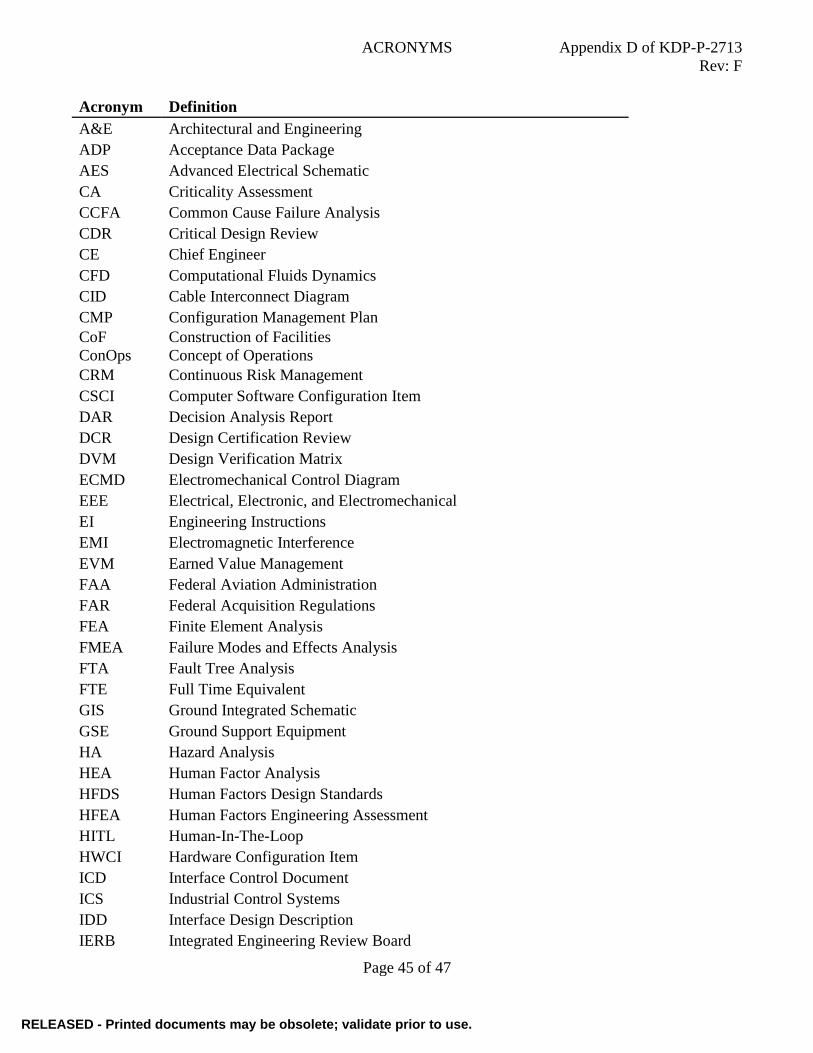
ACRONYMS Appendix D of KDP-P-2713
Rev: F
Page 45 of 47
Acronym Definition
A&E Architectural and Engineering
ADP Acceptance Data Package
AES Advanced Electrical Schematic
CA Criticality Assessment
CCFA Common Cause Failure Analysis
CDR Critical Design Review
CE Chief Engineer
CFD Computational Fluids Dynamics
CID Cable Interconnect Diagram
CMP Configuration Management Plan
CoF
ConOps
Construction of Facilities
Concept of Operations
CRM Continuous Risk Management
CSCI Computer Software Configuration Item
DAR Decision Analysis Report
DCR Design Certification Review
DVM Design Verification Matrix
ECMD Electromechanical Control Diagram
EEE Electrical, Electronic, and Electromechanical
EI Engineering Instructions
EMI Electromagnetic Interference
EVM Earned Value Management
FAA Federal Aviation Administration
FAR Federal Acquisition Regulations
FEA Finite Element Analysis
FMEA Failure Modes and Effects Analysis
FTA Fault Tree Analysis
FTE Full Time Equivalent
GIS Ground Integrated Schematic
GSE Ground Support Equipment
HA Hazard Analysis
HEA Human Factor Analysis
HFDS Human Factors Design Standards
HFEA Human Factors Engineering Assessment
HITL Human-In-The-Loop
HWCI Hardware Configuration Item
ICD Interface Control Document
ICS Industrial Control Systems
IDD Interface Design Description
IERB Integrated Engineering Review Board
RELEASED - Printed documents may be obsolete; validate prior to use.RELEASED - Printed documents may be obsolete; validate prior to use.
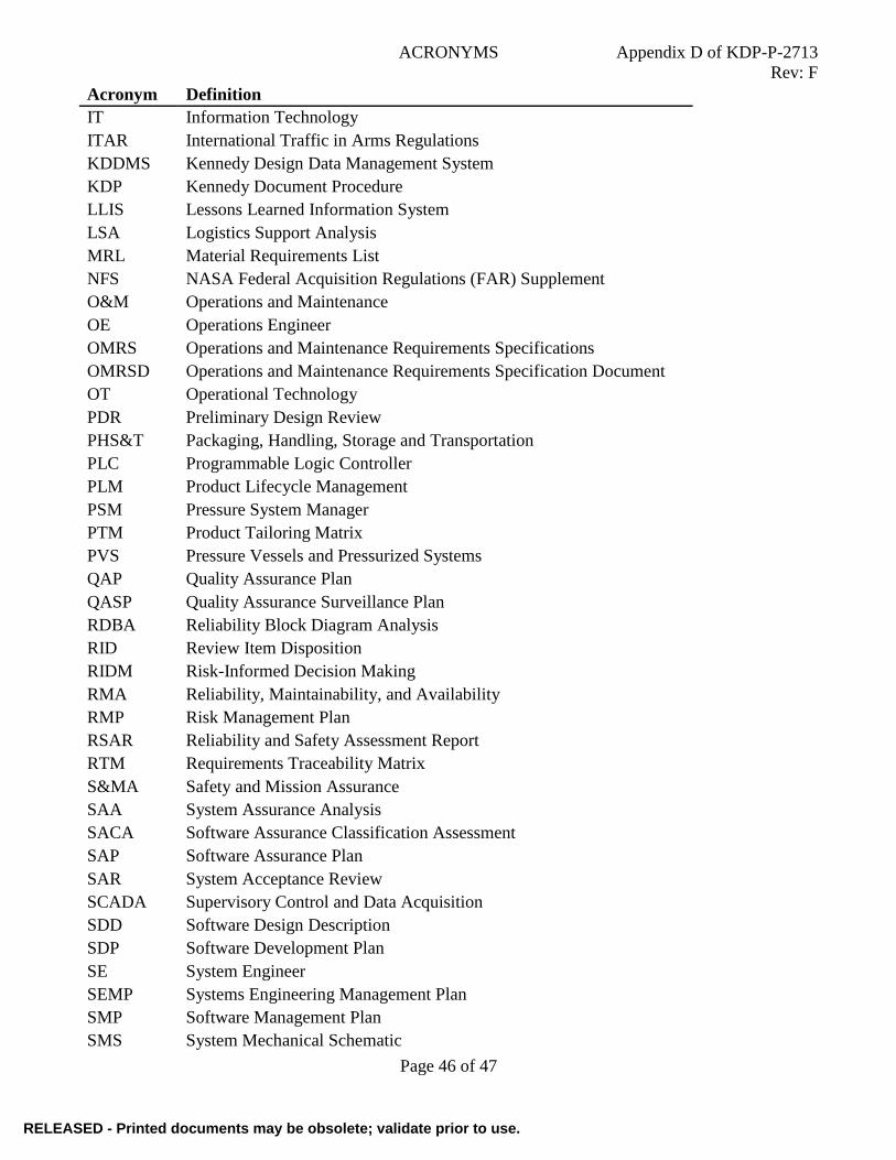
ACRONYMS Appendix D of KDP-P-2713
Rev: F
Page 46 of 47
Acronym Definition
IT Information Technology
ITAR International Traffic in Arms Regulations
KDDMS Kennedy Design Data Management System
KDP Kennedy Document Procedure
LLIS Lessons Learned Information System
LSA Logistics Support Analysis
MRL Material Requirements List
NFS NASA Federal Acquisition Regulations (FAR) Supplement
O&M Operations and Maintenance
OE Operations Engineer
OMRS Operations and Maintenance Requirements Specifications
OMRSD Operations and Maintenance Requirements Specification Document
OT Operational Technology
PDR Preliminary Design Review
PHS&T Packaging, Handling, Storage and Transportation
PLC Programmable Logic Controller
PLM Product Lifecycle Management
PSM Pressure System Manager
PTM Product Tailoring Matrix
PVS Pressure Vessels and Pressurized Systems
QAP Quality Assurance Plan
QASP Quality Assurance Surveillance Plan
RDBA Reliability Block Diagram Analysis
RID Review Item Disposition
RIDM Risk-Informed Decision Making
RMA Reliability, Maintainability, and Availability
RMP Risk Management Plan
RSAR Reliability and Safety Assessment Report
RTM Requirements Traceability Matrix
S&MA Safety and Mission Assurance
SAA System Assurance Analysis
SACA Software Assurance Classification Assessment
SAP Software Assurance Plan
SAR System Acceptance Review
SCADA Supervisory Control and Data Acquisition
SDD Software Design Description
SDP Software Development Plan
SE System Engineer
SEMP Systems Engineering Management Plan
SMP Software Management Plan
SMS System Mechanical Schematic
RELEASED - Printed documents may be obsolete; validate prior to use.RELEASED - Printed documents may be obsolete; validate prior to use.

ACRONYMS Appendix D of KDP-P-2713
Rev: F
Page 47 of 47
Acronym Definition
SOW Statement of Work
SRR System Requirements Review
SRS Software Requirements Specification
SSA Software Safety Analysis
SSP Software Safety Plan
STP Software Test Plan
TBD To Be Determined
TBR To Be Resolved
TCTI Time Compliance Technical Instruction
TRR Test Readiness Review
VDD Version Description Document
WBS Work Breakdown Structure
WYE Work Year Equivalent
RELEASED - Printed documents may be obsolete; validate prior to use.RELEASED - Printed documents may be obsolete; validate prior to use.