rev. 10-06 mueller water distribution products …ggitc.com/abc/home page_renewal/plumbing/fire...
TRANSCRIPT

Rev. 10-06
I
MUELLER®
WATER DISTRIBUTION PRODUCTS CATALOGMueller Co. 500 West Eldorado Street Decatur, Illinois 62525 Phone: 800-423-1323 Fax: 217-425-7537
Mueller Canada 82 Hooper RoadBarrie, Ontario, Canada L4N 8Z9 Phone: 705-719-9965Fax: 705-719-4959
COPYRIGHT JANUARY 1991 MUELLER CO. PRINTED IN U.S.A.

Rev. 4-99
II
Founded in 1857, Mueller Co. has long been rec-ognized as a leading supplier of water distribution products. This catalog presents the broad spectrum of those products, their features and benefits, and includes the needed specifications and ordering information.
Mueller products have established a reputation for high quality and long life. Several factors contribute to the maintenance of that reputation.
DESIGN AND DEVELOPMENT MANUFACTURING AND TESTING
Mueller design engineers set strict tolerances as they develop new products to meet tomorrow’s water distribution system requirements. Extensive devel-opmental testing is conducted before new product release to prove design integrity, performance and value to you.
Manufacturing and assembly of Mueller products follow rigid procedures, with inspection conducted every step of the way. In fact, every person who sees our products during manufacture is considered an inspector. As a final measure of quality control, performance is assured by testing prior to shipment. In many product categories, each and every unit is pressure tested.
DELIVERY AND SERVICEMueller distributors inventory extensive stocks, helping to assure ready availability. Mueller sales representatives, strategically located thoughout North America, are always ready to provide application and installation assistance and help with any special problems.
COMMITTED TO GIVING YOU EXTRA VALUE

Rev. 4-99
IIITERMS AND CONDITIONS
CATALOGThis catalog supersedes all previous catalogs and other literature applying to Mueller® Water Distribution Products. Separate catalogs apply to other Mueller Products.
PATENTSOver the years, most of our products have resulted from extensive research and development work by our Engineering Division. It is our policy to protect these important developments, where possible, by patents. For this reason, many of the products illustrated herein are protected by patents or are the subject matter of pending applications for patent.
DESIGNS Designs and dimensions shown in this catalog are sub-ject to change without notice.
OTHER TERMS Certain other terms including, but not limited to: credit terms, freight allowances; sales, use or other taxes levied on sales transactions; claims for shortage or for goods damaged or lost in transit; and permission to return goods are all apart of the current price sheets ap-plying to this catalog.
TRADEMARKSOne or more of the following trademarks may be shown on all goods of our manufacture or the containers in which they are shipped.
MUELLER HT™ ACTUATORS ADAMS®
MUELLER HP®
ORI-CORP®
LINESEAL®
LINESEAL III®
HI-FLO®
SLIP-HINGE®
SUPER CENTURION 250™ SUPER CENTURION 200™ MUELLER 300™
MUELLER®
ORISEAL®
H M®
CEM-RES®
MUELLER 110®
INSTA-TITE®
CENTURION®
220®
PIPE-SAVER®
FULL-SEAL®
SERVI-SEAL®
XTRA-RANGE®
B-101™ A-3™ CL-12™ C1-36™ MEGA-CUT™ PL-2™ TRU-CUT™ 2360 SERIES™ 2361 SERIES™

Rev. 9-09
IV WARRANTIES
LIMITED WARRANTYMueller Co. warrants its products to be free of defects in workmanship and mate-rial under normal use and service and when used for the purposes and under the conditions for which they are intended, for a period of one year from the date of shipment.
Obligation under this warranty is limited, at Mueller’s option; to adjust, repair or replace, F.O.B. point of manufacture, the defective product. Purchaser must im-mediately notify Mueller Co. in writing of
the claimed defect. Mueller shall have the right to inspect said product and purchaser shall, if requested, return the defective product to Mueller Co. with transporta-tion prepaid. Purchaser shall assume all responsibility and expense for removal and reinstallation and freight charges in connection with the foregoing remedy. Mueller Co. shall not be liable for indi-rect, special, incidental or consequential damage or penalties and does not assume any liability of purchaser to others, or to anyone for injury to persons or property.
TEN YEAR LIMITED WARRANTY ON MUELLER® SUPER CENTURION 200™ AND 250™ FIRE HYDRANTSMueller Co. warrants its SUPER CEN-TURION 200 and 250 Fire Hydrants to be free from defects in material and work-manship under normal use and service for a period of ten (10) years from the date represent- ed by the code cast on the upper barrel of the hydrant, provided the hydrant is installed and maintained according to Mueller instructions, and American Water Works Association publications M17, C502 and C600 and applicable local codes. The foregoing warranty does not cover failure of any part or parts from external forces such as , but not limited to, vandal-ism, vehicular or other impact, applica-tion of excessive torque to the operating mechanism or frost heave.
Should any Mueller manufactured part or parts be proven to have failed to conform to the foregoing warranty, Mueller shall, upon prompt written notice thereof, at its option, repair or replace, F.O.B. point of manufacture, such defective part(s). Mueller shall have the right to inspect the part(s) for which a claim is made under the foregoing warranty and purchaser shall, if requested, return the part(s) to Mueller, transportation prepaid. Purchaser shall assume all responsibility and expense for removal, reinstallation and shipping charges in connection with the foregoing warranty.
THE FOREGOING WARRANTY IS IN LIEU OF ALL OTHER WARRAN-TIES, EXPRESSED OR IMPLIED, INCLUDING THE WARRANTIES OF MERCHANTABILITY AND FITNESS FOR A PARTICULAR PURPOSE. IN NO EVENT SHALL MUELLER CO. BE RESPONSIBLE OR LIABLE FOR ANY INCIDENTAL CONSEQUENTIAL DAM-AGE.
This warranty is a substitute for the war-ranty terms as published in the current Net Trade Price Sheets applying to Mueller Water Distribution Products Catalog, Sec-tions 9, 10, 11, 12, 13, 14, and applies only to MUELLER SUPER CENTURION 200 and 250 Fire Hydrants.
TEN YEAR LIMITED WARRANTY ON MUELLER® 2360 AND 2361 SERIES™ RESILIENT WEDGE VALVES
This warranty is in lieu of all other warran-ties, expressed and implied including the warranty of merchantability.
Any claims or shortages or damages must be in writing within ten days after receipt of shipment. Buyer shall note loss or damage on truck shipments by providing a delivery receipt signed by the driver.
Mueller Co. warrants its Resilient Wedge Valves to be free from defects in material and workmanship under normal use and service for a period of ten (10) years from the date represented by the code cast on the body of the valve, provided the valve is installed and maintained according to Mueller instructions, and American Water Works Association publications C509 and C600 and applicable local codes. The foregoing warranty does not cover failure of any part or parts from external forces such as , but not limited to, vandalism, application of excessive torque to the op-erating mechanism or presence of foreign matter or frost heave. Should any Mueller manufactured part or parts be proven to have failed to conform to the foregoing warranty, Mueller shall, upon prompt written notice thereof, repair or replace, F.O.B. point of manufacture, such defec-
tive part(s). Mueller shall have the right to inspect the part(s) for which a claim is made under the foregoing warranty and purchaser shall, if requested, return the part(s) to Mueller, transportation prepaid. Purchaser shall assume all responsibility and expense for removal, reinstallation and shipping charges in connection with part(s) supplied under
THE FOREGOING WARRANTY IS IN LIEU OF ALL OTHER WARRANTIES, EXPRESSED OR IMPLIED, INCLUD-ING THE WARRANTIES OF MER-CHANTABILITY AND FITNESS. IN NO EVENT SHALL MUELLER CO. BE RESPONSIBLE OR LIABLE FOR ANY INCIDENTAL OR CONSEQUENTIAL DAMAGE
This warranty is a substitute for the war-ranty terms as published in the current Net Trade Price Sheets applying to Mueller Water Distribution Products Catalog, Sections 9, 10, 11, 12, 13, 14, and applies only to MUELLER 2360 and 2361 Series Resilient Wedge Valves. the foregoing warranty.

Rev. 9-09
REQUEST FOR NEW OR MODIFIED PRODUCTS V
Fax Request To: MUELLER CO. ATTN: WATER PRODUCT MARKETING FAX: 217-425-7537
WPR_____ For office use only
Please fill out form as completely as possible
Name __________________________Title _______________ Phone number _____________________________________
Company Name __________________________ Address ___________________________________________________
City _____________________ State ________ Zip _____________ E-mail _______________________________________ Description - as detailed as possible, include sketch or diagram:What is it...(where in your system or company will it be used, such as distribution piping, maintenance, treatment plant, etc.)
Why it's worth exploring...(potential for cost/time savings, efficiency improvements, better safety, easier maintenance, nothing similar available, current items inferior, etc.)
Who..(who will use this item or who will approve its purchase)
What is the estimated annual usage.
When needed.
Sources for more information...(attach if available)
Mail Request To: MUELLER CO. 500 WEST ELDORADO ST. DECATUR, IL 62525 ATTN: WATER PRODUCTMARKETING
Email Request To: [email protected]
ATTN: WATER PRODUCT MARKETING

Rev. 4-99
VI
Use the space below for drawing or sketching

9.1
SEE PAGE 9.28 FOR ORDERING INSTRUCTIONS
Shaded area indicates changes Rev. 9-09
MUELLER® SUPER CENTURION® FIREHYDRANT WITH AQUAGRIP™ SYSTEM
MUELLER AquaGrip System
The MUELLER AquaGrip System includes both the compression connection and the restraint system in one con-venient, quick installation package. This eliminates the need for anchor couplings, tie rods or separate gland-type restraints. The AquaGrip system is available exclusively from Mueller on Centurion Fire Hydrants and 2300 Series Resilient Wedge Valves.
❏ TWO STYLES:DIPS fits DI, C900 PVC and DIPS PE pipe.IPS fits PVC, IPS PE. No special pipe end preparation, and no liner required for PE pipe (DR9-DR17)
❏ NO POINT LOADING OF PIPE — gripper ring encircles pipe for uniform grip without creating points of high stress in pipe wall that could contribute to pipe failure.
❏ PRESSURE RESPONSIVEO-RING SEAL — unique double O-ring uses hydrostatic pressure from inside the pipe to enhance the seal as line pressure increases.
❏ FULLY ASSEMBLED STAB CONNECTION — insert the pipe and tighten the bolts. No need to change-out, add or remove parts. Nothing additional to inventory or handle in the field. No extra bolts to assemble or tighten.
❏ VISUALLY SHOWS WHENPROPERLY TIGHTENED — breakaway nuts snap off using a standard wrench. No special torque requirements. Inner nut remains in place to allow future access to connection, if required. (Lower nut shown before tightening; upper one after tightening.)
❏ INSTALLS IN WETCONDITIONS — no special field conditions required, even installs under water.

9.2
SEE PAGE 9.28 FOR ORDERING INSTRUCTIONS
Rev. 9-09
❏ ANTI-FRICTION WASHER - helps assure easy turning operation for the life of the hydrant.
❏ OIL FILLER PLUG - permits quick check of oil level. Lets you add oil without removing bonnet.
❏ OIL RESERVOIR O-RING SEALS - seal oil in, water out.
❏ STAINLES STEEL SAFETY STEM COUPLING - pulls free if hydrant is hit by a vehicle preventing damage to the stem and main valve. Coupling will not break into pieces that could drop into lower barrel and affect valve opera-tion. Top of lower stem is below the top of the lower barrel so that a tire cannot de-press the stem and open the main valve. Repair is easy and economical.
❏ SAFETY FLANGE - breaks cleanly to help prevent barrel damage, yet is strong enough to withstand normal handling. Allows economi-cal repair, adding of extension section, rotation or changing of upper barrel without digging or water shut-off.
❏ BRONZE UPPER VALVE PLATE - conical design for smooth flow.
❏ DRAIN VALVE FACINGS - specially designed, long-life facings provide effective sealing.
❏ CAST IRON CAP NUT - retains main valve. Seats against cap nut gasket to prevent corrosion of stem threads. Locked in place by a stainless steel lock washer. Mueller HP Epoxy coated for durability.
❏ 250 PSIG - 3-way hydrant: 250 psig (1723 kPa) maximum working pressure, 500 psig (3447kPa)
❏ SHOE DESIGNED FOR MAXIMUMFLOW AND EASY CONNECTION - with its smooth transitional contours, extended neck and integral anti-rotation pads, allowing use of standard tee-head bolts. The inside of the shoe is covered with MUELLER HP ¨ Epoxy Coating. This thermosetting epoxy forms a tough corrosion-resistant barrier to chemicals, physical impact and electrical currents.
MUELLER SUPER CENTURION 250™ 3-Way Fire Hydrant Features ❏ HOLD-DOWN NUT - with integral weather seal. Design discourages unauthorized
removal of the hold-down nut or bronze operating nut. Resilient wiper seal between hold-down nut and operating nut prevents water entry to protect operating nut from freezing. Wiper seal material is resistant to ultra-violet ray deterioration. O-ring seal provides second level of protection.
MUELLER® SUPER CENTURION® FIREHYDRANT WITH AQUAGRIP™ SYSTEM
❏ MEETS OR EXCEEDS - all applicable re-quirements of ANSI/AWWA C502 Standard and UL 246 and FM 1510 specifications.
❏ O-RING SEALS AT BONNET, GROUND, AND SHOE FLANGES - for better leak resistance, easier maintenance.
❏ SEALED OIL RESERVOIR - O-ring sealed to prevent leakage. Provides positive lubrication of stem threads and bearing surfaces each time the hydrant is operated. Filled at the factory.
❏ FULL FLOW OPENINGS - large radius hose and pumper openings produce low friction loss.
❏ FIELD REPLACEABLE HOSE AND PUMPER NOZZLES - O-ring sealed. Threaded in place and retained by stainless steel locks. Nozzles are easily replaced.
❏ ELECTRO-GALVANIZED BOLTS AND NUTS - provide corrosion protection.
❏ NON-KINKING CHAINS - heavy-duty chains are securely attached to the hydrant. Special chain loop permits free turning of the cap.
❏ BRONZE SEAT RING - threaded into drain ring and O-ring sealed. Seat ring is easily removed or installed from above ground. Each time main valve is opened or closed, double drain valves force-flush both drain valve open-ings to keep them open for effective barrel drainage. Bronze drain valves are integral parts of main valve assembly.
❏ REVERSIBLE, COMPRESSION-TYPE MAIN VALVE - closes with pressure for positive seal. Rubber material has long service life, yet is reversible providing a convenient spare in place.

9.3Rev. 9-09
MUELLER® SUPER CENTURION®
FIRE HYDRANTMUELLER SUPER CENTURION 250™ 3-Way Fire Hydrant Features
❏ HOLD-DOWN NUT - with integral weather seal. Design discourages unauthorized re-moval of the hold-down nut or bronze operating nut. Resilient wiper seal between hold-down nut and operating nut prevents water entry to protect operating nut from freezing. Wiper seal material is resistant to ultra-violet ray deterioration. O-ring seal provides second level of protection.
❏ ANTI-FRICTION WASHERhelps assure easy turning operation for the life of the hydrant.
❏ OIL FILLER PLUGpermits quick check of oil level. Lets you add oil without removing bonnet.
❏ OIL RESERVOIR O-RING SEALS seal oil in, water out.
❏ STAINLES STEEL SAFETY STEM COUPLING - pulls free if hydrant is hit by a vehicle preventing damage to the stem and main valve. Coupling will not break into pieces that could drop into lower barrel and affect valve operation. Top of lower stem is below the top of the lower barrel so that a tire cannot depress the stem and open the main valve. Repair is easy and economical.
❏ SAFETY FLANGE - breaks cleanly to help prevent barrel damage, yet is strong enough to withstand normal handling. Allows economical repair, adding of extension sec-tion, rotation or changing of upper barrel without digging or water shut-off.
❏ BRONZE UPPER VALVE PLATE conical design for smooth flow.
❏ DRAIN VALVE FACINGSspecially designed, long-life facings provide effective sealing.
❏ DUCTILE IRON CAP NUT retains main valve. Seats against cap nut gasket to prevent corrosion of stem threads. Locked in place by a stainless steel lock washer. Mueller HP Epoxy coated for durability.
❏ 250 PSIG - 3-way hydrant: 250 psig (1723 kPa) maximum working pressure, 500 psig (3447 kPa)
❏ SHOE DESIGNED FOR MAXIMUMFLOW AND EASY CONNECTION with its smooth transitional contours, extended neck and integral anti-rotation pads, allowing use of standard tee-head bolts. The inside of the shoe is covered with MUELLER HP® Epoxy Coating. This thermosetting epoxy forms a tough corrosion-resistant barrier to chemicals, physical impact and electrical currents.
❏ MEETS OR EXCEEDSall applicable requirements of ANSI/AWWA C502 Standard and UL 246 and FM 1510 specifications.
❏ O-RING SEALS AT BONNET, GROUND, AND SHOE FLANGES for better leak resistance, easier maintenance.
❏ SEALED OIL RESERVOIR - O-ring sealed to prevent leakage. Provides positive lubrication of stem threads and bearing surfaces each time the hydrant is operated. Filled at the factory.
❏ FULL FLOW OPENINGS large radius hose and pumper openings produce low friction loss.
❏ FIELD REPLACEABLE HOSE AND PUMPER NOZZLES - O-ring sealed. Threaded in place and retained by stainless steel locks. Nozzles are easily replaced.
❏ ELECTRO-GALVANIZED BOLTS AND NUTS - provide corrosion protection.
❏ NON-KINKING CHAINS heavy-duty chains are securely attached to the hydrant. Special chain loop permits free turning of the cap.
❏ BRONZE SEAT RING - threaded into drain ring and O-ring sealed. Seat ring is eas-ily removed or installed from above ground. Each time main valve is opened or closed, double drain valves force-flush both drain valve openings to keep them open for effec-tive barrel drainage. Bronze drain valves are integral parts of main valve assembly.
❏ REVERSIBLE, COMPRESSION TYPE MAIN VALVE - closes with pressure for positive seal. Rubber material has long service life, yet is reversible providing a convenient spare in place.
Manufactured under one or more of the following: U.S. Patent No. 4,717,178; 4,842,246.

9.4Rev. 9-09
MUELLER® FIRE HYDRANTS
MUELLER SUPER CENTURION 200™ 2-Way and 1-Way Fire Hydrant
❏ Meets all applicable parts of ANSI/AWWA C502 Standard
❏ Hold-down nut with integral weather seal; designed to discourage unauthorized tampering
❏ Gasket seals at bonnet, ground and shoe flanges
❏ Dry top design with O-ring sealed oil reservoir
❏ Stainless steel safety stem coupling pulls free if hydrant is hit by a vehicle preventing damage to the stem and main valve
❏ Reversible, compression-type main valve closes with pressure for positive seal
❏ Low flow loss design with full flow nozzles and shoe
❏ Field replaceable nozzles
❏ Dual bronze drain ways
❏ 200 psig (1379 kPa) maximum working pressure, 400 psig (2758 kPa) test pressure
MUELLER MODERN CENTURION™ Fire Hydrant
MUELLER CENTURION Spin-In Fire Hydrant
❏ Modern, sleek exterior design
❏ Meets all applicable parts of ANSI/AWWA C502 Standard
❏ Post type dry barrel design
❏ Dry top design with O-ring sealed oil reservoir
❏ Traffic feature
❏ Stainless steel safety stem coupling pulls free if hydrant is hit by a vehicle preventing damage to the stem and main valve
❏ Reversible, compression-type main valve closes with pressure for positive seal
❏ Low flow loss design with full flow nozzles and shoe
❏ Field replaceable nozzles
❏ Dual bronze drain ways
❏ Two way and three way designs
❏ 200 psig (1379 kPa) maximum working pressure, 400 psig (2758 kPa) test pressure
MUELLER 2-1/8" Post and Flush Type Fire Hydrants
❏ 2-1/8" main valve opening
❏ Meets all applicable parts of ANSI/AWWA C502 Standard
❏ Dry barrel design
❏ Used for blow offs, sampling, irrigation, golf course watering, private estates, etc.
❏ Compression type main valve closes with pressure
❏ Bronze drain
❏ Flush type has a cast iron box with lid
❏ 150 psig (1034 kPa) maximum working pressure 300 psig (2068 kPa) test pressure
❏ Lower barrel threaded to fit most sizes of R.D.Wood fire hydrant shoes
❏ Meets all applicable parts of ANSI/AWWA C502 Standard
❏ Post type dry barrel design
❏ Dry top design with O-ring sealed oil reservoir
❏ Traffic feature
❏ Reversible, compression-type main valve closes with pressure for positive seal
❏ Low flow loss design with full flow nozzles and shoe
❏ Field replaceable nozzles
❏ Dual bronze drain ways
❏ Two way and three way design
❏ 200 psig (1379 kPa) maximum working pressure, 400 psig (2758 kPa) test pressure
Manufactured under one or more of the following: U.S. Patent No. 4,717,178; 4,842,246.

9.5Rev. 9-09
MUELLER® O.E.M. FIRE HYDRANTREPAIR PARTS AND REPAIR KITSMUELLER CO. considers a fire hydrant to be a critical piece of emergency equipment used to pre-serve lives and property. For this reason all Mueller Fire Hydrants are designed, built and tested to assure high performance and dependability.
Typical bonnet repair kit
Each component part of a MUELLER Fire Hydrant is specially designed to assure proper and reliable operation. Attention to detail doesn’t stop once the part is designed. Quality control tests are made on all component parts to assure dimensional and mate-rial integrity are maintained. Every MUELLER Fire Hydrant is pressure tested and operated before it leaves our plant to assure it meets our high quality standards.
MUELLER CO. is confident it produces one of the most reliable fire hydrants available and backs this claim with a 10 YEAR LIMITED WARRANTY ON PARTS AND WORKMANSHIP for the MUELLER Super CENTURION® Fire Hydrant. The claim of outstanding performance and reliability is proven by the fact that almost half of all the fire hydrants sold in the United States today are manufac-tured by MUELLER CO.
A fire hydrant is exposed to the elements on a daily basis and over a period of time repairs may even-tually become necessary. MUELLER CO. offers repair kits that have the same parts as are used in our regular production hydrants. When you use genuine MUELLER replacement parts you are assured the part matches the manufacturer’s original equipment specifications with regard to dimensions, materials and performance. Only genuine MUELLER parts are marked with the MUELLER name.
Typical safety flange repair kit
Typical main valve repair kit
Typical shoe repair kit

9.6Rev. 8-04 Shaded area indicates changes
MUELLER® SUPER CENTURION®
FIRE HYDRANT WITH AQUAGRIP™ SYSTEM ❏ Super Centurion 250™
A-421 4-1/2" main valve opening three way (two hose nozzles and one pumper nozzle) A-423 5-1/4" main valve opening three way (two hose nozzles and one pumper nozzle)
❏ 10 year limited warranty on material and workmanship
❏ Meets all applicable parts of ANSI/AWWA C502 Standard
❏ Post type dry barrel design
❏ Dry top design with O-ring sealed oil reservoir
❏ Traffic feature with stainless steel safety stem coupling
❏ Compression-type main valve closes with pressure for positive seal; it is made of rubber and is conveniently reversible providing a spare for long service life (Patent Pending)
❏ Operating nut available in wide variety of shapes and sizes – open left or right
❏ Field replaceable hose and pumper nozzles
❏ Hose and pumper nozzles have large radius, full flow openings for low friction loss
❏ Contoured shoe is designed for full flow
❏ Dual bronze drain valves provide effective barrel drainage
❏ 250 psig (1723 kPa) maximum working pressure, 500 psig (3447 kPa) static test pressure for 3-way hydrants; 200 psig (1379 kPa) maximum working pressure, 400 psig (2758 kPa) static test pressure for 2-way and 1-way hydrants
BURY1-5/8"
18"
32"
Bury - 1'6" (0.46m)minimum; longer by 6"(152 mm) intervals.
8.15 - 8.24
2.50
Dimensions
6" DIPS or IPS
SEE PAGE 9.28 FOR ORDERING INSTRUCTIONS

9.7 Shaded area indicates changes Rev. 9-09
MUELLER® SUPER CENTURION® FIREHYDRANT WITH AQUAGRIP™ SYSTEM
A-1A-85A-3A-84A-5A-6A-7A-8A-9A-10A-11A-12A-13A-14A-15A-16A-17A-18A-19A-20A-21A-22A-23A-24A-25A-26A-27A-28A-29A-30A-31A-32A-33A-34A-35A-36A-37A-38A-39A-40
A-42A-43A-44A-52A-45A-46A-47A-48A-49A-53A-50A-51A-54
A-55 A-56 A-57
MUELLER Super Centurion Fire Hydrant Parts
Cat.part #
Description Material Materialstandard
A-1 Operating Nut Bronze ASTM B584
A-3 Hold Down Nut O-ring Rubber ASTM D2000 BUNA N
A-5 Bonnet O-ring Rubber ASTM D2000 BUNA N
A-6 Anti-friction Washer Celcon
A-7 Oil Plug Brass ASTM B16
A-8 Bonnet Cast Iron ASTM A126 CL.B
A-9 Bonnet Bolt and Nut Steel ASTM A307 Plated
A-10 Bonnet O-ring Rubber ASTM D2000 BUNA N
A-11 Upper Stem Steel ASTM A576 GR.B
A-12 Stem O-ring Rubber ASTM D2000 BUNA N
A-13 Nozzle Lock Stainless Steel ASTM A276
A-14 Pumper Nozzle Bronze ASTM B584
A-15 Pumper Nozzle Gasket Rubber ASTM D2000 Neoprene
A-16 Pumper Nozzle O-ring Rubber ASTM D2000 BUNA N
A-17 Pumper Nozzle Cap Cast Iron ASTM A126 CL.B
A-18 Hose Nozzle Bronze ASTM B584
A-19 Hose Nozzle Gasket Rubber ASTM D2000 Neoprene
A-20 Hose Nozzle O-ring Rubber ASTM D2000 BUNA N
A-21 Hose Nozzle Cap Cast Iron ASTM A126 CL.B
A-22 Cap Chain Steel Plated
A-23 Chain Ring Steel Plated
A-24 Upper Barrel Less Nozzles Cast Iron ASTM A126 CL.B
A-25 Safety Coupling Stainless Steel ASTM A890
A-26 Safety Flange Bolt and Nut Steel ASTM A307 Plated
A-27 Safety Flange O-ring Rubber Cellulose
A-28 Safety Flange Cast Iron ASTM A126 CL.B
A-29 Cotter Pin Stainless Steel ASTM A276
A-30 Clevis Pin Stainless Steel ASTM A276
A-31 Lower Stem Steel ASTM A576 GR.B
A-32 Lower Barrel Cast Iron ASTM A126 CL.B
A-33 Stem Pin Stainless Steel ASTM A276
A-34 Drain Valve Facing Plastic
A-35 Drain Valve Screw Stainless Steel ASTM A276
A-36 Upper Valve Plate (includes A-34 and A-35) Bronze ASTM B584
A-37 Shoe bolt and nut Steel ASTM A307 Plated
A-38 Drain Ring Housing O-ring Rubber ASTM D2000 BUNA N
A-39 Seat Ring Top O-ring Rubber ASTM D2000 BUNA N
A-40 Drain Ring Housing Cast Iron ASTM A126 CL.B
A-41 Drain Ring Housing Bolt and Nut Steel ASTM A307 Plated
A-42 Drain Ring Bronze ASTM B584
A-43 Seat Ring Bronze ASTM B584
A-44 Seat Ring Bottom O-ring Rubber ASTM D2000 BUNA N
A-45 Reversible Main Valve Rubber ASTM 2000
A-46 Lower Valve Plate Cast Iron ASTM A126 CL.B
A-47 Cap Nut Seal Rubber ASTM D2000
A-48 Lock Washer Stainless Steel ASTM A276
A-49 Lower Valve Plate Nut Cast Iron ASTM A126 CL.B
A-50 Shoe Ductile Iron ASTM A536 Grade 65-45-12
A-84 Hold Down Nut Bronze ASTM B584
A-85 Weather Seal Rubber ASTM D2000
A-52 Double O-ring Rubber ASTM D2000
A-53 Gripper Ring Ductile Iron ASTM A536 Grade 65-45-12
A-54 Breakaway nut w/ washer Steel
A-55 T-head bolt Steel
A-56 Intermediate Ring Ductile Iron ASTM A536 Grade 65-45-12
A-57 End-Ring Ductile Iron ASTM A536 Grade 65-45-12
SEE PAGE 9.28 FOR ORDERING INSTRUCTIONS

9.8Rev. 8-04 Shaded area indicates changes
MUELLER® SUPER CENTURION® FIRE HYDRANT
❏ Super Centurion 250™ 3-way catalog numbers (approved to UL 246, FM 1510, ANSI/AWWA C502 Standards) - A-421 4-1/2" main valve opening three way (two hose nozzles and one pumper nozzle) A-423 5-1/4" main valve opening three way (two hose nozzles and one pumper nozzle) Super Centurion 200™ 2-way catalog numbers (approved to ANSI/AWWA C502 Standards) - A-420 4-1/2" main valve opening two way (two hose nozzles)A-422 5-1/4" main valve opening two way (two hose nozzles) A-425 5-1/4" main valve opening two way (two pumper nozzles) Super Centurion 200™ 1-way catalog number(approved to ANSI/AWWA C502 Standards)- A-424 4-1/2" main valve opening one way (one pumper nozzle)
❏ 10 year limited warranty on material and workmanship
❏ Meets all applicable parts of ANSI/AWWA C502 Standard
❏ Post type dry barrel design
❏ Dry top design with O-ring sealed oil reservoir
❏ Traffic feature with stainless steel safety stem coupling
❏ Compression-type main valve closes with pressure for positive seal; it is made of rubber and is conveniently reversible providing a spare for long service life
❏ Operating nut available in wide variety of shapes and sizes-open left or right
❏ Field replaceable hose and pumper nozzles
❏ Hose and pumper nozzles have large radius, full flow openings for low friction loss
❏ Contoured shoe is designed for full flow
❏ Dual bronze drain valves provide effective barrel drainage
❏ 250 psig (1723 kPa) maximum working pressure, 500 psig (3447 kPa) static test pressure for 3-way hydrants;200 psig (1379 kPa) maximum working pressure, 400 psig (2758 kPa) static test pressure for 2-way and 1-way hydrants
Dimensions Non-rotating bolt design: cast-in pads elimi-nate need for anti-rotation bolts.
Front view detail of Mechanical joint (Standard only)
Vertical Flange*
Mechanical joint standard and D-150
FlangeANSI 125/150 or PN 10/16 Drilling
Slip-on
* 4" Vertical shoe available for A-420 and A-421 hydrants.
SEE PAGE 9.28 FOR ORDERING INSTRUCTIONS

9.9 Shaded area indicates changes Rev. 9-09
MUELLER Super Centurion Fire Hydrant Parts
Cat.part#
Description Material Materialstandard
A-1 Operating nut Bronze ASTM B584A-2 Weather cap (not shown; used only on pre-1988 models) Cast iron ASTM A126 CL.BA-3 Hold down nut O-ring Rubber ASTM D2000 BUNA NA-4 Hold down nut (not shown; used only on pre-1988 models) Bronze ASTM B584A-5 Bonnet O-ring Rubber ASTM D2000 BUNA NA-6 Anti-friction washer CelconA-7 Oil plug Brass ASTM B16A-8 Bonnet Cast iron ASTM A126 CL.BA-9 Bonnet bolt and nut Steel ASTM A307 PlatedA-10 Bonnet O-ring (1997 and newer 3-way models; all pre-
1997 models and 1-way and 2-way models have flat gasket)Rubber ASTM D2000 BUNA N
A-11 Upper stem Steel ASTM A576 GR.BA-12 Stem O-ring Rubber ASTM D2000 BUNA NA-13 Nozzle lock Stainless steel ASTM A276A-14 Pumper nozzle Bronze ASTM B584A-15 Pumper nozzle gasket Rubber ASTM D2000 NeopreneA-16 Pumper nozzle O-ring Rubber ASTM D2000 BUNA NA-17 Pumper nozzle cap Cast iron ASTM A126 CL.BA-18 Hose nozzle Bronze ASTM B584A-19 Hose nozzle gasket Rubber ASTM D2000 NeopreneA-20 Hose nozzle O-ring Rubber ASTM D2000 BUNA NA-21 Hose nozzle cap Cast iron ASTM A126 CL.BA-22 Cap chain Steel PlatedA-23 Chain ring Steel PlatedA-24 Upper barrel less nozzles Cast iron ASTM A126 CL.BA-25 Safety coupling Stainless steel ASTM A890A-26 Safety flange bolt and nut Steel ASTM A307 PlatedA-27 Safety flange O-ring (1997 and newer models;
pre-1997 models have flat gasket)Rubber ASTM D2000 BUNA N
A-28 Safety flange Cast iron ASTM A126 CL.BA-29 Cotter pin Stainless steel ASTM A276A-30 Clevis pin Stainless steel ASTM A276A-31 Lower stem Steel ASTM A576 GR.BA-32 Lower barrel Cast iron ASTM A126 CL.BA-33 Stem pin Stainless steel ASTM A276A-34 Drain valve facing PlasticA-35 Drain valve screw Stainless steel ASTM A276A-36 Upper valve plate (includes A-34 and A-35) Bronze ASTM B584A-37 Shoe bolt and nut Steel ASTM A307 PlatedA-38 Drain ring housing O-ring (1997 and newer models;
pre-1997 models have square gasket)Rubber ASTM D2000 BUNA N
A-39 Seat ring top O-ring Rubber ASTM D2000 BUNA NA-40 Drain ring housing Cast iron ASTM A126 CL.BA-41 Drain ring housing bolt and nut (not shown; used only
on pre-1997 model hydrants)Steel ASTM A307 Plated
A-42 Drain ring Bronze ASTM B584A-43 Seat ring Bronze ASTM B584A-44 Seat ring bottom O-ring Rubber ASTM D2000 BUNA NA-45* Reversible main valve (1997 and newer models only; pre-
1997 models use non-reversible main valve and lower valveplate - not shown)
Rubber ASTM D2000
A-46 Lower valve plate (1997 and newer models forreversible main valve; pre-1997 models have non-reversible main valve - not shown)
Cast iron ASTM A126 CL.B
A-47 Cap nut seal Rubber ASTM D2000A-48 Lock washer Stainless steel ASTM A276A-49 Lower valve plate nut Cast iron ASTM A126 CL.BA-50 Shoe** Cast iron ASTM A126 CL. BA-84 Hold down nut Bronze ASTM B584A-85 Weather sealA-51 10.5 oz. hydrant lubricating oil (not shown)
Rubber ASTM D2000
MUELLER® SUPER CENTURION®
FIRE HYDRANT PARTS
* Pre-1997 models may be upgraded to use the reversible main valve by also replacing the lower valve plate with the 1997 model.
** 6" MJ shoe is Ductile Iron, ASTM A536 Grade 65-45-12.
SEE PAGE 9.28 FOR ORDERING INSTRUCTIONS

9.10Rev. 9-09 Shaded area indicates changes
A-359-00 Seat wrench --- universal fit, used to remove main valve and seat ring from bonnet level or ground line. Wrench self-centers on barrel flange. Used on all Super Centurion models and Super 200 and 250.
MUELLER® SUPER CENTURION® FIREHYDRANT MISCELLANEOUS EQUIPMENT
A-311 Operating wrench ---operates nozzle caps, pin and lug type hose couplings, hydrant operating nut, and hold down nut.
A-367 Brass sleeve --- protects O-rings from damage when removing the bonnet from upper stem.
A-316 Nozzle wrench---Used to remove and install threaded in hose and pumper noz-zles.
Sizes: 2-1/2", 3", 3-1/2", 4", 4-1/2", and 5"
A-317 Nozzle lock instal-lation tool --- used to in-stall nozzle locking device.
A-51 Hydrant lubricating oil --- 10.5 ounce container of all-weather oil.
A-311 A-367
A-316
A-359-00
A-317
A-51
A-359 Seat wrench --- universal fit, used to remove main valve and seat ring from bonnet level or ground line. Wrench self-centers on barrel flange. Used on all Centurion, Modern and 107® Hydrants.
A-359
Heavy Duty Centurion Hold Down Nut Wrench
Sizes:
240885
Integral Storz Pumper Connection --- used to quickly connect to hydrants. Available on Centurion 200™, 250™ or Modern hydrant.
Integral Storz Wrench --- used to remove the integral Storz Pumper Connection. Sizes - 4" - 287402
5" - 287403

9.11Rev. 9-09
MUELLER® SUPER CENTURION® FIRE HYDRANT REPAIR KITS
Bonnet Repair Kit Bonnet Repair Kit consists of ---
• (1) Weather seal • (2)HolddownnutO-rings• (2)BonnetO-rings• (1)Bonnet/UpperbarrelO-ring• (1)Anti-frictionwasher• (1)Bonnetflangegasket• (3)StemO-rings• (1)10.5oz.Hydrantlubricatingoil• (1)Instructionsheet
Main Valve Repair Kit
Kit catalog number4-1/2" M.V.O. 5-1/4" M.V.O.
280355 280355
Main Valve Repair Kit consists of ---
• (2) Top seat O-rings • (2)BottomseatO-rings• (1)Mainvalve(reversible)• (1)Lowervalveplate(reversible)• (2)Capnutseals• (1)Bronzeseatring• (1)Instructionsheet
Safety Flange Repair Kit
Kit catalog number4-1/2" M.V.O. 5-1/4"M.V.O.
A-319 A-320
Extension Kit Extension Kit consists of ---
• (1)Stem• (1)Barrel• (1)Stainlesssteelextensionstem
coupling • (1)Extensionflange• (1)Bonnet/UpperbarrelO-ring• (3)Gaskets• (1)Bonnet/UpperbarrelO-ring• (8)Boltsandnuts• (2)Clevispins• (3)Cotterpins• (1)Instructionsheet• (1)10.5oz.hydrantlubricatingoil• Extensionlengths:0'-6",1'-0",
1'-6",2'-0",2'-6",3'-0",3'-6", 4'-0"
Safety Flange Repair Kitconsists of --- • (1)Safetyflange• (2)Gaskets• (8)Safetyflangebolts
and nuts • (1)SafetyflangeO-ring• (1)Bonnet/Upperbarrel
O-ring • (1)10.5oz.hydrantlubricat-
ing oil • (1)Stainlesssteelsafety
stem coupling • (2)Clevispins• (3)Cotterpin• (1)Instructionsheet
Shoe Repair Kit Shoe Repair Kit consists ---
• (2)Drainvalvefacings• (6)Drainvalvefacingscrews• (1)Drainringhousinggasket• (1)TopseatO-ring• (1)BottomseatO-ring• (1)Gasket• (1)Mainvalve(reversible)• (1)Lowervalveplate(reversible)• (1)Capnutseal• (1)Lockwasher• (6)Shoeboltsandnuts• (2)Drainringboltsandnuts• (1)10.5oz.hydrantlubricatingoil• (1)Instructionsheet
Kit catalog number4-1/2" M.V.O. 5-1/4" M.V.O.
280356 280357
Kit catalog number4-1/2" M.V.O. 5-1/4" M.V.O.
280358 280359
Kit catalog number4-1/2" M.V.O. 5-1/4"M.V.O.
A-300 A-301
Replaces 107 hydrant bonnet with Centurian stop-in-bonnet style. Open left, 1-1/2" pentagon operating nut.
Bonnet Replacement Kitconsists of ---• (1)Bonnet• (1)Bonnetgasket• (8)Bonnetbolts/nuts• (1)Operatingnut• (1)Holddownnut• (1)Stopnut• (1)Oilplug• (1)Anti-frictionwasher• (1)Weatherseal• (1)HolddownnutO-ring• (2)BonnetO-rings• (3)SteamO-rings• (1)Upperstemassembly• (1)10.5oz.hydrantlubricatingoil• (1)Instructionsheetform11089
A-417107® Conversion Kit

9.12Rev. 8-04
MUELLER® MODERN CENTURION® FIRE HYDRANT
❏ Catalog numbers - A-441 5-1/4" main valve opening two way (two hose nozzles) A-442 5-1/4" main valve opening three way (two hose nozzles and one pumper nozzle)
❏ Modern, sleek exterior design
❏ Meets all applicable parts of ANSI/AWWA C502 Standard
❏ Post type dry barrel design
❏ Dry top design with O-ring sealed oil reservoir
❏ Traffic feature with stainless steel safety stem coupling
❏ Compression type main valve closes with pressure for positive seal; it is made of rubber and is conveniently reversible providing a spare for long service life
❏ Operating nut available in wide variety of shapes and sizes
❏ Field replaceable hose and pumper nozzles
❏ Hose and pumper nozzles have large radius, full flow openings for low friction loss
❏ Contoured shoe is designed for full flow
❏ Dual bronze drain valves provide effective barrel drainage
❏ 200 psig (1379 kPa) maximum working pressure, 400 psig (2758 kPa) test pressure
Dimensions
Mechanical joint
standard and D-150
FlangeANSI 125/150 or PN 10/16 Drilling
Non-rotating bolt design: cast-in pads eliminate need for anti-rotation bolts.
Front view detail of Mechanical joint (Standard only)
Slip-on
Vertical Flange
SEE PAGE 9.28 FOR ORDERING INSTRUCTIONS

9.13 Shaded area indicates changes Rev. 9-09
MUELLER Modern Centurion Fire Hydrant Parts
Cat.partno.
Description Material Materialstandard
A-3 Hold down nut O-ring Rubber ASTM D2000 BUNA NA-5 Bonnet O-ring Rubber ASTM D2000 BUNA NA-6 Anti-friction washer CelconA-7 Oil plug Brass ASTM B16A-12 Stem O-ring Rubber ASTM D2000 BUNA NA-13 Nozzle lock Stainless steel ASTM A276A-14 Pumper nozzle Bronze ASTM B584A-15 Pumper nozzle gasket Rubber ASTM D2000 NeopreneA-16 Pumper nozzle O-ring Rubber ASTM D2000 BUNA NA-17 Pumper nozzle cap Cast iron ASTM A126 CL.BA-18 Hose nozzle Bronze ASTM B584A-19 Hose nozzle gasket Rubber ASTM D2000 NeopreneA-20 Hose nozzle O-ring Rubber ASTM D2000 BUNA NA-21 Hose nozzle cap Cast iron ASTM A126 CL.BA-22 Cap chain Steel PlatedA-23 Chain ring Steel PlatedA-25 Safety coupling Stainless steel ASTM 890A-26 Safety flange bolt and nut Steel ASTM A307 PlatedA-27 Safety flange gasket Rubber ASTM D2000 BUNA NA-28 Safety flange Cast iron ASTM A126 CL.BA-29 Cotter pin Stainless steel ASTM A276A-30 Clevis pin Stainless steel ASTM A276A-31 Lower stem Steel ASTM A576 GR.1117A-32 Lower barrel Cast iron ASTM A126 CL.BA-33 Stem pin Stainless steel ASTM A276A-34 Drain valve facing PlasticA-35 Drain valve screw Stainless steel ASTM A276A-36 Upper valve plate (includes A-34 and A-35) Bronze ASTM B584A-37 Shoe bolt and nut Steel ASTM A307 PlatedA-38 Drain ring housing O-ring (1997 and newer
models; pre-1997 models have flat gasket)Rubber ASTM D2000 BUNA N
A-39 Seat ring top O-ring Rubber ASTM D2000 BUNA NA-40 Drain ring housing Cast iron ASTM A126 CL.BA-41 Drain ring housing bolt and nut (not shown;
used only on pre-1997 model hydrants)Steel ASTM A307 Plated
A-42 Drain ring Bronze ASTM B584A-43 Seat ring Bronze ASTM B584A-44 Seat ring bottom O-ring Rubber ASTM D2000 BUNA NA-45* Reversible main valve (1997 and newer
models only; pre-1997 models use non-reversible main valve and lower valve plate -not shown)
Rubber ASTM D2000
A-46 Lower valve plate (1997 and newer nodels forreversible main valve; pre-1997 models havenon-reversible main valve - not shown)
Cast iron ASTM A126 CL.B
A-47 Cap nut seal Rubber ASTM D2000A-48 Lock washer Stainless steel ASTM A276A-49 Lower valve plate nut Cast iron ASTM A126 CL.BA-50 Shoe** Cast iron ASTM A126 CL.BA-51 10.5 oz. hydrant lubricating oil (not shown)A-52 Operating nut Bronze ASTM B584A-53 Weather cap Cast iron ASTM A126 CL. BA-54 Hold down nut Bronze ASTM B584A-55 Housing Cast iron ASTM A126 CL.BA-56 Housing bolt Steel ASTM A307 PlatedA-57 Top housing O-ring Rubber ASTM D2000A-58 Upper stem Steel ASTM A576 GR.1117A-59 Upper barrel less nozzles Cast iron ASTM A126 CL.B
MUELLER® MODERN CENTURION® FIRE HYDRANT PARTS
* Pre-1997 models may be upgraded to use the reversible main valve by also replacing the lower valve plate with the 1997 model.
** 6" MJ shoe material is Ductile Iron, ASTM A536 Grade 65-45-12.
SEE PAGE 9.28 FOR ORDERING INSTRUCTIONS

9.14Rev. 9-09 Shaded area indicates changes
A-359-00 Seat wrench --- universal fit, used to remove main valve and seat ring from bonnet level or ground line. Wrench self-centers on barrel flange. Used on all Super Centurion models and Super 200 and 250.
MUELLER® MODERN CENTURION® FIREHYDRANT MISCELLANEOUS EQUIPMENT
A-311 Operating wrench --- operates nozzle caps, pin and lug type hose couplings, hydrant operating nut, and hold down nut.
A-368 Brass sleeve --- protects O-rings from damage when removing the bonnet from upper stem.
A-316 Nozzle wrench--- Used to remove and install threaded in hose and pumper nozzles.
Sizes: 2-1/2", 3", 3-1/2", 4", 4-1/2", and 5"
A-317 Nozzle lock installation tool --- used to install nozzle locking device.
A-51 Hydrant lubricating oil --- 10.5 ounce container of all-weather oil.
A-311
A-368
A-316
A-317
A-359-00
A-359 Seat wrench --- universal fit, used to remove main valve and seat ring from bonnet level or ground line. Wrench self-centers on barrel flange. Used on all Centurion, Modern and 107® Hydrants.
A-359
A-51
Integral Storz Pumper Connection --- used to quickly connect to hydrants. Available on Centurion 200™, 250™ or Modern hydrant.
Integral Storz Wrench --- used to remove the integral Storz Pumper Connection. Sizes - 4" - 287402
5" - 287403

9.15Rev. 9-09
MUELLER® MODERN CENTURION® FIRE HYDRANT REPAIR KITS
Shoe Repair KitShoe Repair Kit consists of---• (2)Drainvalvefacings• (6)Drainvalvefacingscrews• (1)Drainringhousinggasket• (1)DrainringhousingO-ring• (1)TopseatO-ring• (1)BottomseatO-ring• (1)Mainvalve(reversible)• (1)Lowervalveplate(reversable)• (1)Capnutseal• (1)Lockwasher• (6)Shoeboltsandnuts• (2)Drainringboltsandnuts• (1)10.5oz.hydrantlubricatingoil• (1)Instructionsheet
Kit catalog number5-1/4" M.V.O.
280357
Main Valve Repair KitMain Valve Repair Kit consists of---• (2)TopseatO-rings• (2)BottomseatO-rings• (1)Mainvalve(reversible)• (1)Lowervalveplate(reversible)• (2)Capnutseals• (1)Bronzeseatring• (1)Instructionsheet
Extension KitExtension Kit consists of ---
• (1)Stern• (1)Barrel• (1)Stainlesssteelextensionstemcoupling• (1)Extensionflange• (2)Gaskets• (8)Boltsandnuts• (2)Clevispins• (3)Cotterpins• (1)10.5oz.hydrantlubricatingoil• (1)Instructionsheet• Extensionlengths:0'-6",1'-0",1'-6",2'-0",
2'-6",3'-0",3;-6",4'-0",4'-6"and5'-0"
Kit catalog number5-1/4" M.V.O.
A-320
Kit catalog number5-1/4" M.V.O.
280359
Safety Flange Repair KitSafety Flange Repair Kit consists of---• (1)Safetyflange• (2)Gaskets• (8)Safetyflangeboltsandnuts• (1)SafetyflangeO-ring• (1)Bonnet/UpperbarrelO-ring• (1)10.5oz.hydrantlubricatingoil• (1)Stainlesssteelsafetystemcoupling• (2)Clevispins• (3)Cotterpins• (1)Instructionsheet
Kit catalog number5-1/4" M.V.O.
A-301

9.16Rev. 8-04
MUELLER® CENTURION SPIN-IN FIRE HYDRANT
❏ Catalog numbers--A-465 4-1/2"* main valve opening three way (two hose nozzles and one pumper nozzle) fits 4-1/2" bronze lined R.D.Wood shoe A-466 4-1/2"* main valve opening three way (two hose nozzles and one pumper nozzle) fits 4" regular R.D.Wood shoe A-467 5-1/4" main valve opening three way (two hose nozzles and one pumper nozzle) fits 6" regular R.D.Wood shoe A-468 5-1/4" main valve opening three way (two hose nozzles and one pumper nozzle) fits 5" bronze lined R.D.Wood shoe
❏ Meets all applicable parts of ANSI/AWWA C502 Standard
❏ Post type dry barrel design
❏ Dry top design with O-ring sealed oil reservoir
❏ Traffic feature with stainless steel safety stem coupling
❏ Compression type patented main valve closes with pressure for positive seal; it is made of rubber and is conveniently reversible providing a spare for long service life
❏ Operating nut available in wide variety of shapes and sizes
❏ Field replaceable hose and pumper nozzles
❏ Hose and pumper nozzles have large radius, full flow openings for low friction loss
❏ Dual bronze drain valves provide effective barrel drainage
❏ 200 psig (1379 kPa) maximum working pressure, 400 psig (2758 kPa) test pressure
*4-1/2" M.V.O. hydrants have 5-1/4" bonnets, upper barrels, safety flanges and lower barrels and are marked 5-1/4" even though the main valve opening is 4-1/2".
Dimensions
SEE PAGE 9.28 FOR ORDERING INSTRUCTIONS

9.17 Shaded area indicates changes Rev. 9-09
MUELLER Centurion Spin-in Fire Hydrant
Cat.partno.
Description Material Materialstandard
A-1 Operating nut Bronze ASTM B584A-2 Weather cap (not shown; used only on pre-
1988 models)Cast iron ASTM A126 CL.B
A-3 Hold down nut O-ring Rubber ASTM D2000 BUNA NA-4 Hold down nut (not shown; used only on pre-
1988 models)Bronze ASTM B584
A-5 Bonnet O-ring Rubber ASTM D2000 BUNA NA-6 Anti-friction washer CelconA-7 Oil plug Brass ASTM B16A-8 Bonnet Cast iron ASTM A126 CL.BA-9 Bonnet bolt and nut Steel ASTM A307 PlatedA-10 Bonnet O-ring (1997 and newer models; pre-
1997 models have flat gasket)Rubber ASTM D2000 BUNA N
A-11 Upper stem Steel ASTM A576 GR.BA-12 Stem O-ring Rubber ASTM D2000 BUNA NA-13 Nozzle lock Stainless
steelASTM A276
A-14 Pumper nozzle Bronze ASTM B584A-15 Pumper nozzle gasket Rubber ASTM D2000 NeopreneA-16 Pumper nozzle O-ring Rubber ASTM D2000 BUNA NA-17 Pumper nozzle cap Cast iron ASTM A126 CL.BA-18 Hose nozzle Bronze ASTM B584A-19 Hose nozzle gasket Rubber ASTM D2000 NeopreneA-20 Hose nozzle O-ring Rubber ASTM D2000 BUNA NA-21 Hose nozzle cap Cast iron ASTM A126 CL.BA-22 Cap chain Steel ElectrogalvanizedA-23 Chain ring Steel ElectrogalvanizedA-24 Upper barrel less nozzles Cast iron ASTM A126 CL.BA-25 Safety coupling Steel ANSI C1018 PlatedA-26 Safety flange bolt and nut Steel ASTM A307 PlatedA-27 Safety flange O-ring (1997 and newer models;
pre-1997 models have flat gasket)Rubber ASTM D2000 BUNA N
A-28 Safety flange Cast iron ASTM A126 CL.BA-29 Cotter pin Stainless steel ASTM A276A-30 Clevis pin Stainless steel ASTM A276A-31 Lower stem Steel ASTM A576 GR.BA-32 Lower barrel Cast iron ASTM A126 CL.BA-33 Stem pin Stainless steel ASTM A276A-34 Drain valve facing PlasticA-35 Drain valve screw Stainless steel ASTM A276A-36 Upper valve plate (includes A-34 and A-35) Bronze ASTM B584A-45* Reversible main valve (1997 and newer models
only; pre-1997 models use non-reversible mainvalve and lower valve plate - not shown)
Rubber ASTM D2000
A-46 Lower valve plate (1997 and newer models forreversible main valve; pre-1997 models havenon-reversible main valve - not shown)
Cast iron ASTM A126 CL.B
A-47 Cap nut seal Rubber ASTM D2000
A-48 Lock washer Stainless steel ASTM A276A-49 Lower valve plate nut Cast iron ASTM A126 CL.BA-51 10.5 oz. hydrant lubricating oil (not shown)A-84 Hold down nut Bronze ASTM B584A-85 Weather seal Rubber ASTM D2000A-200 Sleeve O-ring Rubber ASTM D2000 NitrileA-201 Sleeve Copper ASTM B75A-202 Stop nut Ductile iron ASTM A395A-250 Seat ring Bronze ASTM B584A-251 Top seat ring gasket Rubber ASTMA-252 Bottom seat ring gasket Rubber ASTM
D2000 NitrileD2000 Nitrile
MUELLER® CENTURION® SPIN-IN FIRE HYDRANT PARTS
* Pre-1997 models may be upgraded to use the reversible main valve by also replacing the lower valve plate with the 1997 model.
SEE PAGE 9.28 FOR ORDERING INSTRUCTIONS

9.18Rev. 8-04 Shaded area indicates changes
A-359 Seat wrench --- universal fit, used to remove main valve and seat ring from bonnet level or ground line. Wrench self-centers on barrel flange. Used on all Centurion Modern and 107® Hydrants.
A-359
MUELLER® CENTURION® SPIN-IN FIRE HYDRANT MISCELLANEOUS EQUIPMENT
A-311 Operating wrench --- operates nozzle caps, pin and lug type hose couplings, hydrant operating nut, and hold down nut.
A-367 Brass sleeve --- protects O-rings from damage when removing the bonnet from upper stem.
A-316 Nozzle wrench--- Used to remove and install threaded in hose and pumper nozzles.
Sizes: 2-1/2", 3", 3-1/2", 4", 4-1/2", and 5"
A-317 Nozzle lock installation tool --- used to install nozzle locking device.
A-51 Hydrant lubricating oil --- 10.5 ounce container of all-weather oil.
A-311 A-367
A-316
A-317
A-51

9.19Rev. 9-09
MUELLER® CENTURION® SPIN-IN FIREHYDRANT REPAIR KITS
Bonnet Repair KitBonnet Repair Kit consists of---• (1)Weatherseal• (1)HolddownnutO-ring• (1)BonnetO-ring• (1)Bonnet/UpperbarrelO-ring• (1)Anti-frictionwasher• (1)Bonnetgasket• (2)StemO-rings• (1)10.5oz.Hydrantlubricatingoil
Kit catalog number5-1/4" M.V.O.
280355
Extension KitExtension Kit consists of ---• (1)Stem• (1)Barrel• (1)Bonnet/UpperbarrelO-ring• (1)Stainlesssteelextensionstem
coupling• (1)Extensionflange• (1)SafetyflangeO-ring• (2)Gaskets• (8)Boltsandnuts• (2)Clevispins• (2)Cotterpins• (1)10.5oz.hydrantlubricatingoil• (1)Instructionsheet
Kit catalog number5-1/4" M.V.O.
A-320
Safety Flange Repair KitSafety Flange Repair Kit consists of---• (1)Safetyflange• (2)Gaskets• (8)Safetyflangeboltsandnuts• (1)SafetyflangeO-ring• (1)Bonnet/UpperbarrelO-ring• (1)10.5oz.hydrantlubricatingoil• (1)Stainlesssteelsafetystem
coupling• (2)Clevispins• (3)Cotterpins• (1)Instructionsheet
Kit catalog number5-1/4" M.V.O.
A-301

9.20Rev. 8-04
MUELLER® 5-1/4" FLUSH TYPEFIRE HYDRANT
❏ Catalog Numbers ---A-415 5-1/4" main valve opening three way(two hose nozzles and one pumper nozzle)
❏ Meets all applicable parts of ANSI/AWWA C502 Standard
❏ Flush type dry barrel design
❏ Dry top design with O-ring sealed oil reservoir
❏ Cast iron flush box with non-locking lid
❏ Compression type patented main valve closes with pressure for positive seal; it is made of rubber and is conveniently reversible providing a spare for long service life
❏ Operating nut available in wide variety of shapes and sizes
❏ Hose and pumper nozzles have large radius, full flow openings for low friction loss
❏ Contoured shoe is designed for full flow
❏ Dual bronze drain valves provide effective barrel drainage
❏ 150 psig (1034kPa) maximum working pressure, 300 psig (2068 kPa) test pressure
Dimensions
Mechanical joint - standard and D-150
Flanged
Slip-on
SEE PAGE 9.28 FOR ORDERING INSTRUCTIONS

9.21 Shaded area indicates changes Rev. 8-04
MUELLER® 5-1/4" FLUSH TYPEFIRE HYDRANT
1 Flush Box Lid (non-locking) Cast iron ASTM A126 CL. B2 Lift Handle3 Lift Handle Nut4 Flush Box Cast iron ASTM A126 CL. B5 Pumper Nozzle Cap Cast iron ASTM A126 CL. B 6 Pumper Nozzle Gasket Rubber ASTM D2000 Neoprene7 Pumper Nozzle Bronze ASTM B5848 Hose Nozzle Cap Cast iron ASTM A126 CL. B9 Hose Nozzle Gasket Rubber ASTM D2000 Neoprene10 Hose Nozzle Bronze ASTM B58411 Oil Screw for operating nut Brass ASTM B3612 Operating Nut Bronze ASTM B58413 Oil Screw in Hold Down Nut Brass ASTM B3614 Hold Down Nut Bronze ASTM B58415 Upper Barrel Cast iron ASTM A126 CL. B16 Hold Down Nut O-ring Rubber ASTM D2000 Neoprene17 O-ring Seal Rubber ASTM D2000 Neoprene18 Cap Screw Steel19 Barrel Flange Gasket Rubber ASTM D2000 Neoprene20 Lower Barrle Cast iron ASTM A126 CL. B21 Stem Steel ASTM A576 GR. B22 Upper Valve Plate Bronze ASTM B58423 Drain Valve Facing Leather 24 Drain Valve Facing Screw Stainless Steel ASTM A30725 Seat Ring Bronze ASTM B58426 Shoe Bolt & Nut Steel ASTM A307 Plated28 Stem Pin Stainless Steel29* Main Valve 1997 and newer modles for reversible main valve; pre 1997 modlesl have non-reversible main vlave and lower valve plate - not shown 30 Lower Valve Plate Cast iron ASTM A126 CL. B 1997 and newer modles for reversible main valve; pre 1997 modlesl have non-reversible main vlave and lower valve plate - not shown31 Valve Plate Nut Bronze ASTM B58432 Cap Nut Seal 33 Lock Washer34 Drain Ring 35 Drain Ring Houseing36 Shoe37 Pumper Nozzle O-ring 38 Hose Nozzle O-ring39 Nozzle Lock40 Chain Hook41 Chain42 Top Seat O-ring43 Bottom Seat O-ring44 Drain Ring O-ring
MUELLER 5-1/4" Flush Type Fire Hydrant
Cat.partno.
Description Material Materialstandard
* Pre-1997 models may be upgraded to use the reverisble main valve by also replacing the lower main valve plate with the 1997 model.
SEE PAGE 9.28 FOR ORDERING INSTRUCTIONS
1
98141112131523
6
73739417101521202824232226253443
2930
333136
19
16
3938
41
40
18
42
4435
32

9.22Rev. 8-04 Shaded area indicates changes
MUELLER® 5-1/4" FLUSH TYPE FIREHYDRANT MISCELLANEOUS EQUIPMENT
A-314 Operating wrench --- operates nozzle caps, pin and lug type hose couplings, hydrant operating nut, and hold down nut.
A-346 Seat wrench --- Adjustable, used to remove main valve and seat ring from ground line level. For use with A-415 hydrant.
A-314
A-316 Nozzle wrench --- Used to remove and install threaded in hose and pumper nozzles.
Sizes: 2-1/2", 3", 3-1/2", 4", 4-1/2", and 5"
A-317 Nozzle lock installation tool --- used to install nozzle locking device.
A-316
A-346
A-317


9.24Rev. 9-09
MUELLER® 2-1/8" POST TYPEFIRE HYDRANT
❏ Catalog numbers -- A-411 2-1/8" main valve opening two way (two 2-1/2" hose nozzles) A-411 2-1/8" main valve opening one way (one 2-1/2" hose nozzle)
❏ Meets all applicable parts of ANSI/AWWA C502 Standard
❏ Post type dry barrel design
❏ Compression type main valve closes with pressure
❏ Operating nut available in wide variety of shapes and sizes
❏ Field replaceable hose nozzles
❏ Hose nozzles have large radius, full flow openings for low friction loss
❏ Contoured shoe is designed for full flow
❏ Dual bronze drain valves provide effective barrel drainage
❏ 150 psig (1034 kPa) maximum working pressure, 300psig (2068 kPa) test pressure
Dimensions
Mechanical joint
Flange
Threaded
SEE PAGE 9.28 FOR ORDERING INSTRUCTIONS

9.25Rev. 8-04
MUELLER® 2-1/8" POST TYPEFIRE HYDRANT
MUELLER 2-1/8" Post Type Fire Hydrant
Cat.partno.
Description Material Material standard
1 Oil screw for operating nut Brass ASTM B36
2 Operating nut Bronze ASTM B584
3 Hold down nut Bronze ASTM B584
6 Operating nut O-ring Rubber ASTM D2000 BUNA-N
8 Hose nozzle cap Cast iron ASTM A126 CL. B
9 Hose nozzle Bronze ASTM B584
13 Stem Steel ASTM A576 GR. B
14 Drain valve screw Stainless steel ASTM A307
15 Upper valve plate* Bronze ASTM B584
16 Drain valve facing Plastic
17 Shoe gasket Rubber ASTM D2000
18 Main valve Rubber ASTM D2000
19 Shoe Cast iron ASTM A126 CL. B
20 Valve plate nut Bronze ASTM B584
21 Lower valve plate Cast iron ASTM A126 CL.B
23 Hose nozzle O-ring Rubber ASTM D2000 Neoprene
24 Seat ring Bronze ASTM B584
25 Seat ring gasket Copper ASTM A372
31 Oil screw Brass ASTM B36
31B O-ring (for oil screw) Rubber ASTM D2000 BUNA-N
36 Nozzle cap chain Steel Plated
37 Barrel flange bolt and nut Steel ASTM A307 Plated
38 Barrel flange gasket Rubber ASTM D2000
39 Shoe bolt and nut Steel ASTM A307 Plated
40 Upper barrel Cast iron ASTM A126 CL. B
41 Lower barrel Cast iron ASTM A126 CL. B
42 O-ring Rubber ASTM D2000
44 Valve nut washer Stainless steel ASTM A276
45 Valve nut seal Rubber ASTM D2000
46 Nozzle lock Stainless steel ASTM A276
47 Hose nozzle gasket Rubber ASTM D2000 Neoprene
A-312 Operating wrench--- operates nozzle caps, pin and lug type hose couplings, hydrant operating nut and hold down nut.
* Includes items #14 and #16.
For pre-1986 models refer to parts drawing on page 9.35.
A-347 Seat wrench--- Adjustable, used to remove main valve and seat ring from ground line level.
A-316 Nozzle wrench--- Used to remove and install threaded in hose and pumper nozzles.
A-312
A-317 Nozzle lock installation tool--- Used to install nozzle locking device.
A-317
A-347
A-316
SEE PAGE 9.28 FOR ORDERING INSTRUCTIONS

9.26Rev. 8-04
MUELLER® 2-1/8" FLUSH TYPE FIRE HYDRANT
❏ Catalog numbers--- A-412 2-1/8" main valve opening one way (one 2-1/2" hose nozzle) non-locking lid
❏ Meets all applicable parts of ANSI/AWWA C502 Standard
❏ Flush type dry barrel design
❏ Compression type main valve closes with pressure
❏ Cast iron flush box with non-locking lid
❏ Operating nut available in wide variety of shapes and sizes
❏ Field replaceable hose nozzles
❏ Hose nozzles have large radius, full flow openings for low friction loss
❏ Contoured shoe is designed for full flow
❏ Dual bronze drain valves provide effective barrel drainage
❏ 150 psig (1034 kPa) maximum working pressure, 300 psig (2068 kPa) test pressure
Dimensions
Mechanical joint
Flange
Threaded
SEE PAGE 9.28 FOR ORDERING INSTRUCTIONS
- 3"

9.27Rev. 8-04
MUELLER® 2-1/8" FLUSH TYPEFIRE HYDRANTMUELLER 2-1/8" Flush Type Fire Hydrant
Cat.partno.
Description Material Material standard
1 Oil screw for operating nut Brass ASTM B362 Operating nut Bronze ASTM B5843 Hold down nut Bronze ASTM B5846 Operating nut O-ring Rubber ASTM D2000 BUNA N8 Hose nozzle cap Cast iron ASTM A126 CL. B9 Hose nozzle Bronze ASTM B58414 Drain valve screw Stainless steel ASTM A30715 Upper valve plate* Bronze ASTM B58416 Drain valve facing Plastic17 Shoe gasket Rubber ASTM D200018 Main valve Rubber ASTM D200019 Shoe Cast iron ASTM A126 CL. B20 Valve plate nut (for use on pre-1986 models;
1986 and newer models use numbers 43, 44, 45)Bronze ASTM B584
21 Lower valve plate Cast iron ASTM A126 CL.B23 Hose nozzle gasket Rubber ASTM ASTM D2000 Neoprene24 Seat ring Bronze ASTM B58425 Seat ring gasket Copper ASTM A37231 Oil screw Brass ASTM B3638 Barrel flange gasket Rubber ASTM D200039 Shoe bolt and nut Steel ASTM A307 Plated42 O-ring Rubber ASTM D200043 Cap nut (for use on 1986 and newer models with
numbers 44 and 45; not shown)Bronze ASTM B584
44 Valve nut washer (used with numbers 43 and 45;not shown)
Stainlesssteel
ASTM A276
45 Valve nut seal (used with numbers 43 and 44;not shown)
Rubber ASTM D2000
46 Nozzle lock Stainless steel ASTM A27647 Upper barrel Cast iron ASTM A126 CL. B48 Flush box Cast iron ASTM A126 CL. B49 Flush box lid (non-locking) Cast iron ASTM A126 CL.B50 Cap screw Steel Electrogalvanized51 Stem Steel ASTM A576 GR. B52 Lower barrel Cast iron ASTM A126 CL. B
*Includes items 14 and 16.
A-313 Operating wrench--- Operatesnozzle caps, pin and lug type hose couplings, hydrant operating nut and hold down nut.
A-313
A-344 Seat wrench--- Adjust-able, used to remove main valve and seat ring from ground line level.
A-344
A-316 Nozzle wrench--- Used to remove and install threaded in hose and pumper nozzles.A-316
A-317 Nozzle lock installation tool--- Used to in-stall nozzle locking device.
A-317
SEE PAGE 9.28 FOR ORDERING INSTRUCTIONS

9.28Rev. 8-04
10. Hose nozzle threading Send a sample of the male coupling on hydrant nozzle to show threads desired, EXCEPT in the following cases(a) if using National Standard, specify accordingly (b) if we have previously furnished hydrants to the same location and there is no change (complete records are kept on file in our Engineering Department for reference).
11. Pumper nozzle threading Same instructions as 10 above.
12. Color Unless otherwise specified, the hydrant will be enameled above ground with fire hydrant red. When so ordered, we will enamel any color (or colors) specified to match your existing standards.
When ordering parts, specify the following:
1. Year date shown on hydrant barrel 2. Part number and name 3. Size and catalog number of hydrant 4. Direction of opening 5. Depth of bury 6. Bonnet markings 7. Type of inlet connection 8. Nozzle specifications (see steps 10 and 11 above)
Contact your MUELLER Distributor or MUELLER Customer Service Center for repair parts for discontinued MUELLER Fire Hydrants.
National Standard hose coupling thread specificationsA. Nominal inside diameter of nozzle 2-1/2" 3" 3-1/2" 4" 4-1/2"Number of threads per inch 7-1/2 6 6 4 4B. Major diameter nozzle thread Max. 3.0686 3.6239 4.2439 5.0109 5.7609
Min. 3.0366 3.5879 4.2079 4.9609 5.7109C. Pitch diameter nozzle thread Max. 2.9820 3.5156 4.1356 4.8485 5.5985
Min. 2.9660 3.4976 4.1176 4.8235 5.5735D. Minor diameter nozzle thread Max. 2.8954 3.4073 4.0273 4.6861 5.4361E. Diameter pilot nozzle 2.850 3.354 3.973 4.610 5.357*F. Length of thread-nozzle 1" 1-1/8" 1-1/8" 1-1/4" 1-1/4"G. Face to start of second turn 1/4" 5/16" 5/16" 7/16" 7/16"H. Major diameter cplg. thread Min. 3.0836 3.6389 4.2639 5.0359 5.7859I. Pitch diameter couplingthread
Max. 3.0130 3.5486 4.1736 4.8985 5.6485Min. 2.9970 3.5306 4.1556 4.8735 5.6235
J. Minor diameter couplingthread
Max. 2.9424 3.4583 4.0833 4.7611 5.5111Min. 2.9104 3.4223 4.0473 4.7111 5.4611
K. Depth of coupling 15/16" 1-1/16" 1-1/16" 1-3/16" 1-3/16"
* Manufacturers standard NOTE: All dimensions are in inches and all dimensional data and tolerances are in accord with ANSI B26.
When ordering Fire Hydrants, specify the following: 1. Quantity If more than one size, quantity of each.
2. Size of main valve opening
3. Catalog number of Fire Hydrant
4. Nozzle arrangement The catalog number indicates the normal arrangements of hose and pumper nozzles. If a different arrangement is desired, specify the size and number of hose and pumper nozzles required.
5. Depth of trench or bury Distance from ground line to bottom of connecting pipe. "Trench" and "ditch" are the same as "bury". "Cover" is the distance from the ground to the top of the connecting pipe.
6. Size of inlet connection
7. Type of inlet connection
8. Size and shape of operating nut National Standard is 1-1/2" pentagon, measured from point to opposite flat. Square and hexagon or other sizes of pentagon can also be furnished. Size is determined by measuring from flat to opposite flat on square and hexagon, and from point to opposite flat on pentagon. Measurements must be taken at base of nut.
9. Direction of opening Open left (counter-clockwise) or open right (clockwise).
MUELLER® FIRE HYDRANT ORDERING INSTRUCTIONS

9.29Rev. 9-09
MUELLER® IMPROVED® FIRE HYDRANT PARTS
HYDRANT WITH BRASS SAFETY STEM COUPLING
HYDRANT WITH STEEL SAFETY STEM COUPLING
H-102 LOCK WASHER
H-51 OPERATING NUT
H-52 WEATHER CAP
H-101 HOLD DOWN NUT O-RING
H-100 BONNET O-RING
H-53 HOLD DOWN NUT
H-98 OIL FILLER PLUG
H-99 BONNET
H-59 BONNET GASKET
H-93 O-RING PACKING
H-65 BONNET BOLT
H-66 PUMPER NOZZLE
H-67 PUMPER NOZZLE CAP
H-70 HOSE NOZZLE
H-68 PUMPER NOZZLE GASKET
H-71 HOSE NOZZLE CAP
H-72 HOSE NOZZLE GASKET
H-69 NOZZLE CAP CHAIN
H-73 UPPER BARREL
H-74 UPPER STEM
H-94 SET SCREW
H-95 SAFETY SLEEVE
H-75 SAFETY STEM COUPLING
H-76 SAFETY FLANGE GASKET
H-77 SAFETY FLANGE
H-78 SAFETY FLANGE BOLT
H-79 LOWER STEM
H-80 LOWER BARREL
H-81 DRAIN VALVE FACING
H-82 DRAIN VALVE FACING SCREW
H-83 UPPER VALVE PLATE
H-84 SHOE GASKET
H-85 SHOE BOLT
H-87 SEAT RING
H-86 METALLIC GASKET
H-88 MAIN VALVE
H-89 LOWER VALVE PLATE
H-90 VALVE PLATE NUT
H-91 CAP NUT
H-92 SHOE
H-96 HYDRANT LUBRICATING OIL
(not shown)
H-102 LOCK WASHER H-51 OPERATING NUT H-52 WEATHER CAP H-101 HOLD DOWN NUT O-RING H-100 BONNET O-RING H-53 HOLD DOWN NUT H-98 OIL FILLER PLUG H-99 BONNET H-59 BONNET GASKET H-65 BONNET BOLT H-93 O-RING PACKING H-66 PUMPER NOZZLE H-67 PUMPER NOZZLE CAP H-70 HOSE NOZZLE H-68 PUMPER NOZZLE GASKET H-71 HOSE NOZZLE CAP H-72 HOSE NOZZLE GASKET H-69 NOZZLE CAP CHAIN H-73 UPPER BARREL H-103 UPPER STEM H-136 CLEVIS PINS H-125 SAFETY STEM CPLG. H-78 SAFETY FLANGE BOLT H-76 SAFETY FLANGE GASKET H-77 SAFETY FLANGE H-137 COTTER PINS H-104 LOWER STEM H-80 LOWER BARREL H-81 DRAIN VALVE FACING H-82 DRAIN VALVE FACING SCREW H-83 UPPER VALVE PLATE H-84 SHOE GASKET H-85 SHOE BOLT H-87 SEAT RING H-86 METALLIC GASKET H-88 MAIN VALVE H-89 LOWER VALVE PLATE H-90 VALVE PLATE NUT H-91 CAP NUT H-92 SHOE H-96 HYDRANT LUBRICATING OIL (not shown)
9.30Rev. 9-09
MUELLER® IMPROVED FIRE HYDRANT BONNET PARTS
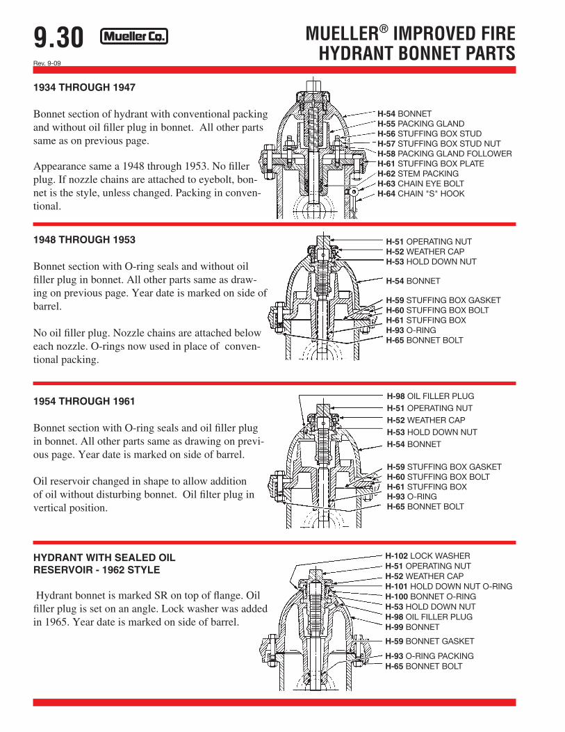
1934 THROUGH 1947
Bonnet section of hydrant with conventional packing and without oil filler plug in bonnet. All other parts same as on previous page.
Appearance same a 1948 through 1953. No filler plug. If nozzle chains are attached to eyebolt, bon-net is the style, unless changed. Packing in conven-tional.
1948 THROUGH 1953
Bonnet section with O-ring seals and without oil filler plug in bonnet. All other parts same as draw-ing on previous page. Year date is marked on side of barrel.
No oil filler plug. Nozzle chains are attached below each nozzle. O-rings now used in place of conven-tional packing.
1954 THROUGH 1961
Bonnet section with O-ring seals and oil filler plug in bonnet. All other parts same as drawing on previ-ous page. Year date is marked on side of barrel.
Oil reservoir changed in shape to allow addition of oil without disturbing bonnet. Oil filter plug in vertical position.
HYDRANT WITH SEALED OIL RESERVOIR - 1962 STYLE
Hydrant bonnet is marked SR on top of flange. Oil filler plug is set on an angle. Lock washer was added in 1965. Year date is marked on side of barrel.
H-54 BONNETH-55 PACKING GLANDH-56 STUFFING BOX STUDH-57 STUFFING BOX STUD NUTH-58 PACKING GLAND FOLLOWERH-61 STUFFING BOX PLATEH-62 STEM PACKINGH-63 CHAIN EYE BOLTH-64 CHAIN "S" HOOK
H-102 LOCK WASHERH-51 OPERATING NUTH-52 WEATHER CAPH-101 HOLD DOWN NUT O-RINGH-100 BONNET O-RINGH-53 HOLD DOWN NUTH-98 OIL FILLER PLUGH-99 BONNET
H-59 BONNET GASKET
H-93 O-RING PACKINGH-65 BONNET BOLT
H-98 OIL FILLER PLUGH-51 OPERATING NUTH-52 WEATHER CAPH-53 HOLD DOWN NUTH-54 BONNET
H-59 STUFFING BOX GASKETH-60 STUFFING BOX BOLTH-61 STUFFING BOXH-93 O-RINGH-65 BONNET BOLT
H-51 OPERATING NUTH-52 WEATHER CAPH-53 HOLD DOWN NUT
H-54 BONNET
H-59 STUFFING BOX GASKETH-60 STUFFING BOX BOLTH-61 STUFFING BOXH-93 O-RINGH-65 BONNET BOLT

9.31Rev. 9-09
HYDRANT WITH CAST IRON
SAFETY STEM COUPLING (All other parts same as
drawing at left)
H-126 STEM PIN
H-111 SCREW PIN
MUELLER® 107® FIRE HYDRANT PARTSHYDRANT WITH STEEL SAFETY STEM COUPLING
H-139 BONNET ASSEMBLY COMPLETE (includes following*)H-110* OPERATING NUT AND WEATHER CAPH-111* SCREW PINH-112* OPERATING SCREWH-113* OPERATING SCREW SEAL
H-114* ANTI-FRICTION WASHER
H-115* STEM NUT
H-116* OPERATING SCREW BEARINGH-117* BEARING SEAL
H-118* HOLDDOWN NUT
H-119* BONNETH-59* BONNET GASKETH-120* STEM NUT SEAL
H-121* WIPER RINGH-122* BONNET BOLT
H-123 UPPER STEMH-124 UPPER STEM SEAL
H-66 PUMPER NOZZLEH-67 PUMPER NOZZLE CAP
H-68 PUMPER NOZZLE GASKETH-69 CAP CHAINH-70 HOSE NOZZLE
H-71 HOSE NOZZLE CAPH-72 HOSE NOZZLE GASKET
H-73 UPPER BARRELH-125 SAFETY STEM COUPLING
H-136 CLEVIS PINH-76 SAFETY FLANGE GASKET
H-77 SAFETY FLANGEH-78 SAFETY FLANGE BOLT
H-80 LOWER BARRELH-137 COTTER PINH-127 LOWER STEM
H-128 UPPER VALVE PLATE
H-84 SHOE GASKET
H-85 SHOE BOLTH-132 SEAT RINGH-133 SEAT RING SEAL
H-134 DRAIN VALVE SEALH-135 LOWER STEM SEAL
H-129 MAIN VALVEH-130 LOWER VALVE PLATE
H-131 LOCK WASHER
H-138 SHOE
H-91 CAP NUT
H-126 STEM PINH-96* HYDRANT LUBRICATING OIL (not shown)
SEE PAGE 9.28 FOR ORDERING INSTRUCTIONS

9.32Rev. 9-09
MUELLER® MODERN IMPROVED® FIRE HYDRANT PARTS
H-51 OPERATING NUTH-100 HOUSING O-RINGH-201 WEATHER CAPH-101 HOLD DOWN NUT O-RINGH-203 LOCK WASHERH-202 HOLD DOWN NUTH-98 OIL FILLER PLUGH-66 PUMPER NOZZLE
H-68 PUMPER NOZZLE GASKETH-207 PUMPER NOZZLE CAPH-69 CAP CHAIN
H-93 STEM O-RINGSH-206 UPPER STEMH-204 UPPER BARREL
H-70 HOSE NOZZLEH-72 HOSE NOZZLE GASKETH-205 HOSE NOZZLE CAPH-209 SAFETY FLANGE BOLT & NUT
H-210 SAFETY FLANGE CLIPH-208 UPPER BARREL SEALH-136 CLEVIS PINSH-125 SAFETY STEM COUPLINGH-137 COTTER PINSH-80 LOWER BARRELH-211 LOWER STEM
H-212 UPPER VALVE PLATE
H-81 DRAIN VALVE FACINGH-82 DRAIN VALVE FACING SCREWH-213 SEAT RINGH-85 SHOE BOLT & NUTH-215 SEAT RING SEAL
H-88 MAIN VALVEH-89 LOWER VALVE PLATEH-131 LOCK WASHERH-91 CAP NUT
H-216 STEM PINH-217 SEAT RING O-RING SEALH-84 SHOE GASKET
H-214 SHOEH-96 HYDRANT LUBRICATING OIL (not shown)
SEE PAGE 9.28 FOR ORDERING INSTRUCTIONS

9.33Rev. 9-09
MUELLER® STANDARD FIRE HYDRANT PARTS
31 OIL SCREW FOR HOLD DOWN NUT1 OIL SCREW FOR OPERATING NUT2 OPERATING NUT6 O-RING3 HOLD DOWN NUT
42 O-RING
5 BONNET
33 BONNET BOLT & NUT7 BONNET GASKET8 HOSE NOZZLE CAP9 HOSE NOZZLE23 HOSE NOZZLE GASKET
10 PUMPER NOZZLE
11 PUMPER NOZZLE CAP
12 PUMPER NOZZLE GASKET36 NOZZLE CAP CHAIN40 UPPER BARREL37 BARREL FLANGE BOLT & NUT38 GASKET FOR BARREL FLANGE41 LOWER BARREL13 STEM14 DRAIN VALVE SCREW
15 UPPER VALVE PLATE
16 DRAIN VALVE FACING
39 SHOE BOLT & NUT
17 SHOE GASKET
24 SEAT RING
25 METALLIC GASKET18 MAIN VALVE21 LOWER VALVE PLATE20 VALVE PLATE NUT19 SHOE43 CAP NUT (FOR 5-1/4" ONLY)
SEE PAGE 9.28 FOR ORDERING INSTRUCTIONS

9.34Rev. 9-09
MUELLER® HI-FLO® WET BARRELFIRE HYDRANT PARTS
MUELLER HI-FLO Wet Barrel Fire Hydrant
Cat.partno.
Description Material Material standard
1 Pumper nozzle cap gasket Rubber ASTM D2000
2 Pumper nozzle o-ring Rubber ASTM D2000
3 Cotter pin Silicon bronze
4 Anti-friction washer Celcon
5 Seat washer Rubber ASTM D2000
6 O-ring Rubber ASTM D2000
7 Stem Bronze ASTM B584
8 Stuffing box o-ring Rubber ASTM D2000
9 Stuffing box Bronze ASTB B584
10 Barrel o-ring Rubber ASTM D2000
11 Hose nozzle cap gasket Rubber ASTM D2000
12 Hose nozzle o-ring Rubber ASTM D2000
13 Cotter pin Silicon bronze Silicon bronze
14 Anti-friction washer Celcon
15 Seat washer Rubber ASTM D2000
16 O-ring Rubber ASTM D2000
17 Stem Bronze ASTM B584
18 Stuffing box o-ring Rubber ASTM D2000
19 Stuffing box Bronze ASTM B584
20 Barrel o-ring Rubber ASTM D2000
21 Retaining ring Steel
- Rivet (not illustrated) Copper
SEE PAGE 9.28 FOR ORDERING INSTRUCTIONS