retrofitting suds at industrial premises
TRANSCRIPT
2nd International Conference on Natural Hazards & Infrastructure
23-26 June, 2019, Chania, Greece
*Corresponding author: V. Krivtsov, WA modular Building, EGIS, Heriot Watt University, Edinburgh EH14 4AS, Scotland; email [email protected] or [email protected]
Retrofitting SUDS at Industrial Premises
V. Krivtsov*, S. Arthur, C. Semple, A. E. Sevilla Heriot Watt University
B.J. D’Arcy Independent environmental consultant
ABSTRACT
SEPA policy (1996) states that it is mandatory for new developments to provide SUDS on site: at source on individual premises; for conveyance and, also, on a regional basis. These SUDS features can serve the whole estate or a part thereof and are all part of the treatment train that consists of various levels of control, including source, local and regional controls. As part of the pollution risk management of the collective impact of an industrial estate, the day-to-day runoff quality and contingency planning functions for SUDS on individual premises and the road network can be vital, an approach consistent with the polluter pays principle. The focus of the research presented here was an industrial estate in Scotland. Runoff from the estate is polluted and discharges into the Caw Burn which is known to have water quality problems. Detailed visits to propose specific SUDS retrofits have identified opportunities at source on several premises, two possibilities for conveyance SUDS; and one opportunity for a regional detention basin. This paper explores the potential of a regional SUDS retrofit (public facility consisting of a detention basin and connecting swales) and provides a detailed insight into possibilities of retrofitting source control SUDS at a typical industrial premises. A number of combinations of various SUDS components (including permeable block pavements, pervious asphalt, swales, flow attenuation tanks, raised bed planters and detention basins) have been assessed as regards their functional characteristics, economic costs and logistical constraints. The most comprehensive retrofit would cost over £95,000, which may be prohibitive for a medium-sized company. A partial retrofit, however, is feasible: e.g. installation of raised raingarden planters and flow attenuation tanks would cost only a few thousand pounds. Adjacent to the premises, there is an extensive green space capable of accommodating a reasonably sized detention basin. Importantly, that could also serve a public road. Furthermore, several companies situated farther away could be connected to this feature by a conveyance swale. Ideally, such a basin would be adopted by Scottish Water and designed to alleviate consequences of a 100 years return period storm.
Keywords: SUDS retrofit, detention basin, swale, cost, permeable pavement, runoff attenuation INTRODUCTION SUDS are a statutory requirement for new developments in Scotland. Scottish Environment Protection Agency (SEPA) policy from the outset (1996) has been to seek provision of SUDS on industrial estates: at source on individual premises; for conveyance; and on a regional basis, serving the whole estate or a part thereof (levels of treatment, in a spatial sense). That approach is consistent with the polluter pays principle; pollution risk

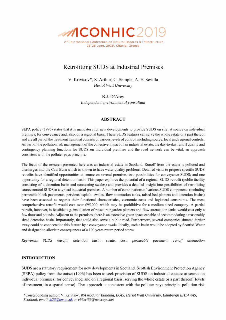
management includes day-to-day runoff quality (collective impact of an industrial estate) and contingency planning functions for SUDS on individual premises and the road network. This paper reports on a specific case study dealing with potential SUDS retrofits at industrial premises. The focus of the research was Houston Industrial Estate (HIE), Livingston, West Lothian. Runoff from the estate is polluted and discharges into the Caw Burn which is known to have water quality problems. This paper provides a detailed insight into possibilities of retrofitting SUDS at one typical premises - ‘Transcal’, and discusses the possibility of linking it, as well as a number of other premises, to a proposed public facility. Transcal Company Transcal (Figure 1) is situated on Firth Road at HIE. The building construction consists of three sides of corrugated metal with the fourth side, facing approximately north-north-west, mostly comprised of glass. The roof is angled with a central peak, falling to the east and west, and is constructed of cladding. A basic assessment of the structure contours from the provided borehole data (not shown) have led to the conclusion that a clay layer will cause any infiltrated runoff to travel in an approximate east-south-east direction. Company Background and Operations The ownership and control of the site mean that any options available to Transcal have a straight forward decision process. Transcal manufactures seats and interiors for major car companies and first-class aircraft seats. There is no treating of hides on site as the leather and faux leather used is treated elsewhere and transported to the site. Because of this, there is not likely to be any hazardous chemicals or processes involved in the day-to-day operation of the manufacturing line. Any water used in Transcal is domestic, i.e. toilets and taps, and therefore does not require any special treatment before being discharged to the foul water network. Current Drainage System
Road Surfaces and Car Park The current system of drainage uses the traditional method, i.e. impermeable surfaces channelling runoff to a surface water drain, the latter going to the Caw Burn. This will allow any particulates to be washed into the drain with the possibility of eventually clogging the inlet. During the site visit, it was revealed that there have been no problems with flooding. This indicates that the drainage is sufficient for current ambient weather conditions. In addition to the main car park, the delivery yard is also used for parking vehicles, private and company owned. During the site visit, there was only one marked company vehicle present. There are 48 marked spaces in the car park and delivery yard. This presents a normal risk with the potential release of fluids from any vehicles in poorly maintained condition.
Delivery Yard It was noted that there is a significant amount of debris and clutter in the delivery yard which has the potential to contaminate runoff if not disposed of or if no measures are taken to isolate from runoff. This debris consists
of an open skip, a pallet of gritting salt, two large storage containers, various sizes and lengths of rusted metal parts and other material.
Figure 1. Aerial view of the site (Google DigitalGlobe, 2016) and layout of proposed SUDS features. Contrast adjusted for clarity of SUDS placement.
Roof Down pipes were located along two sides of the building, 4 each on the east and west sides, leading to the surface water drain. The likelihood of significant forms of pollution coming from the roof is low. The most likely contamination coming from the roof are leaves and atmospheric fallout. While there are no trees directly overhanging the Transcal building, which is approximately 7 metres in height, there are some close by in a

green space. Wind may cause the leaves and grit to become resuspended and deposited on the roof. The source of the grit and other particulates are the nearby roads to the north and south of Transcal. The presence of these contaminants in the surface water network is unlikely to be a cause for environmental concern although it may affect the efficiency of the network by causing blockages or obstructions downstream. A visual inspection of the roof was not undertaken due to Health & Safety concerns, so the condition is unknown. If the cladding is in a well-maintained condition, there is very little chance of contamination entering the network. A poorly maintained roof may be a source of contamination in the form of flakes of paint and/ or rust.
Green Space There are large areas of green space within the Transcal boundary around two sides of the building that are currently not being used but it does provide natural drainage. SUDS retrofit options The total permeable and impermeable areas on the Transcal site are, respectively, 4449 m2 and 4851 m2. There is a potential for several SUDS features to be installed as detailed below. All the options will be considered using the following scenarios: a) Accommodation of runoff from the car park and delivery yard using the detention basin sizes recommended by Table 4 of Stovin and Swan (2007) and rescaled to Transcal premises catchment. b) Accommodation of runoff from the car park and delivery yard, and the additional roundabout catchment using the detention basin sizes recommended by Table 4 of Stovin and Swan (2007) and rescaled to Transcal premises catchment. c) Accommodation of runoff from the car park and delivery yard, and the additional roundabout catchment from a 30-year RP storm. Using data from CEH, the depth of water from a 30-year RP storm was used to determine the volume of water needed to be stored.
Road Surfaces and Car Park The slope and orientation of the clay layer is important to ascertain as this is an impermeable material. Because of the impermeability, this could influence the direction of water flow. A geomembrane and regrading of the slope may be needed to prevent water from infiltrating to the clay layer and flowing underneath the building. This could cause issues in the substructure and is to be avoided at all costs. The geomembrane and regrading has not been included in the costs at this time as it may not be needed. There are two features that can be used to provide permeability of the surface of the Transcal site. One method of providing permeability on larger areas is the use of permeable asphalt (PA). This provides a method of runoff infiltration allowing the gradual attenuation of the water through sub layers. This method also traps contaminants and reduces the risk of their transfer to the sewer network or groundwater. This material could be used throughout the site by removing the impermeable paving and resurfacing. The use of permeable block paving (PBP) is now widely used as a means of providing a permeable surface for car parking spaces and smaller driveways. The block paving works in a similar fashion to the permeable asphalt by infiltration and attenuation. The presence of a clay soil will make infiltration slow. Some excavation and backfilling with granular soil could provide storage, the depth of which will have to be determined through a
complete design. Because of the limited size of the impermeable surface, the use of permeable block paving could be considered. Depending on the configuration chosen, there are three available options:
Option 1: PA across all surfaces
Option 2: PA on road surfaces, PBP on car park spaces
Option 3: PBP on car park spaces only
The delivery yard, which is used by heavy goods vehicles (HGVs) up to a maximum gross mass of 44 tonnes (44000 kg) (Department for Transport, 2010), cannot be resurfaced with permeable paving because it runs the risk of being compacted by the heavy vehicles, requiring repair and extra cost.
Delivery Yard Some housekeeping of the yard will reduce the potential of contaminants reaching the detention basin ensuring more efficient operation for longer. This will reduce maintenance and additional costs. Keeping the road salt covered and dry will ensure that salt crystals are not needlessly washed into the sewer or detention basin when the roads do not require treatment. Proper disposal or recycling of unwanted metal and other objects will reduce the possibility of contamination from rust particles. A covered or enclosed skip will prevent general waste being washed out and into the drain and detention basin. This will keep these facilities free of waste, maintaining efficiency and increasing the time between maintenance periods. There are several ways that the yard can be modified so that the risk of contamination of runoff is reduced. The primary solution is replacing the drain in the centre of the yard with an oil interceptor system with alarm. This separator allows the water to pass through while retaining any oil, thus, preventing it from entering the sewer system. This type of system with an alarm is required under the Pollution Prevention Guidance, PPG3 (Environment Agency, Scottish Environment Protection Agency and Environment and Heritage Service, 2006). The installation of a small gully or channel leading to a detention basin in the green space adjacent to the yard is a viable option to redirect surface runoff from the drain. The excess water will infiltrate through the detention basin capturing any particulates and oil residue from the clutter and vehicles operating in the yard.
Roof There is little scope to modify the roof to provide a means of attenuating flow or providing pollution control. A green roof could be installed but the modifications needed to make that feasible would be expensive and are likely to seriously impact on the day to day running of the business during any construction. A simpler and much cheaper solution is the installation of attenuation tanks, attenuation boxes, rain gardens or raised bed planters that are fed by the down pipes. Regardless of the method used, the downpipes will have to be disconnected from draining directly to the sewer network. There are several potential techniques to deal with runoff from roofs. The attenuation boxes, also known as soakaway crates, are used below ground and can be wrapped in a semi-permeable material and allowed to drain off over a longer period. Another option is to wrap the box in an impermeable cover. This stores the water and allows control of when and how much water is released at any one time. Attenuation tanks are used above ground and store any run off from the roof. The stored water is then released back into the ground or local sewer network in a controlled manner. Attenuation tanks could be used on the west side of the building on the path leading from the car park. The main considerations for using above ground tanks are ease of installation and maintenance. While the
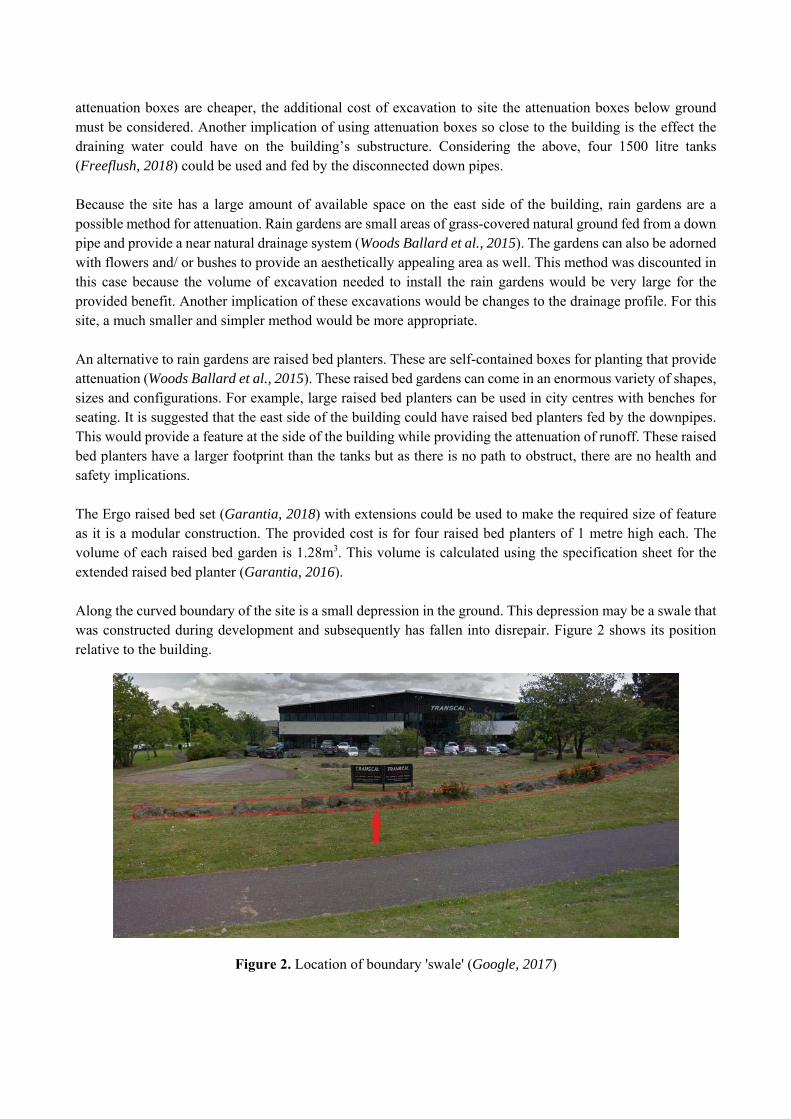
attenuation boxes are cheaper, the additional cost of excavation to site the attenuation boxes below ground must be considered. Another implication of using attenuation boxes so close to the building is the effect the draining water could have on the building’s substructure. Considering the above, four 1500 litre tanks (Freeflush, 2018) could be used and fed by the disconnected down pipes. Because the site has a large amount of available space on the east side of the building, rain gardens are a possible method for attenuation. Rain gardens are small areas of grass-covered natural ground fed from a down pipe and provide a near natural drainage system (Woods Ballard et al., 2015). The gardens can also be adorned with flowers and/ or bushes to provide an aesthetically appealing area as well. This method was discounted in this case because the volume of excavation needed to install the rain gardens would be very large for the provided benefit. Another implication of these excavations would be changes to the drainage profile. For this site, a much smaller and simpler method would be more appropriate. An alternative to rain gardens are raised bed planters. These are self-contained boxes for planting that provide attenuation (Woods Ballard et al., 2015). These raised bed gardens can come in an enormous variety of shapes, sizes and configurations. For example, large raised bed planters can be used in city centres with benches for seating. It is suggested that the east side of the building could have raised bed planters fed by the downpipes. This would provide a feature at the side of the building while providing the attenuation of runoff. These raised bed planters have a larger footprint than the tanks but as there is no path to obstruct, there are no health and safety implications. The Ergo raised bed set (Garantia, 2018) with extensions could be used to make the required size of feature as it is a modular construction. The provided cost is for four raised bed planters of 1 metre high each. The volume of each raised bed garden is 1.28m3. This volume is calculated using the specification sheet for the extended raised bed planter (Garantia, 2016). Along the curved boundary of the site is a small depression in the ground. This depression may be a swale that was constructed during development and subsequently has fallen into disrepair. Figure 2 shows its position relative to the building.
Figure 2. Location of boundary 'swale' (Google, 2017)

As Figure 3 shows, this ‘swale’ also has boulders in it. This feature and the boulders potentially marks the boundary of the Transcal site (Thomson, 2017).
Figure 3. Depression with boulders (left) and location of potential detention basin (right)
This feature leads down to the path running along the eastern side of the site, and it may be possible to create a small drainage SUDS component at this location. That will store any excess water during storm events and allow drainage over a period of time after the event. Figure 3 above shows where the feature may terminate with the swale discharging to the other end. This swale will be used as an attenuation swale as specified in the SUDS Manual (Woods Ballard et al., 2015) if infiltration rates of the ground conditions allow. The possibility of creating a retention pond was immediately discarded as Transcal was concerned about the health and safety implications of having a body of water beside the path. It would be possible to provide a fence but the visual impact on the surrounds may be considered too intrusive and an additional expense. The alternative of a detention basin was much more acceptable as the detention basin will be in a drained state except during storm events.
Additional Considerations It is possible that the runoff from the roundabout to the northwest of the site could be diverted to make use of the SUDS features being proposed on the Transcal site. This may be used to encourage the local council to subsidise or share the cost of construction. By preventing runoff from entering the sewer, this will reduce the volume of water to the network, freeing up capacity and a reduction of the amount of water to be treated prior to discharge to local water bodies. The total additional catchment area (see Figure 1) has been estimated as 4156m2, a size that has been chosen to include the entire roundabout and part of the road to the north of Transcal. Only the impermeable area will be used in subsequent calculations which accounts for approximately 60% of the additional catchment or 2494m2. This size is an approximation and a topographic survey of the area would be needed to determine the fall of the road and provide a more accurate estimate of the catchment.

Size of SUDS Features To determine the required size of the SUDS features that could be placed on site, several sources were used. The main source was an article by Stovin and Swan (2007) and this was used to determine the sizes of the swale and detention basins. From the required size of the detention basin and swale, it was possible to calculate more precise dimensions. For the swale on the Transcal site, the base width will be that of the current feature marking the potential boundary, approximately 1m. The swale sizes will be given using the general parameters given in the SUDS Manual (Woods Ballard et al., 2015). These parameters are base width of 0.5-2m, normal maximum depth of water of 0.4-0.6m and a maximum slope of 1 in 3 with preferred slope of 1 in 4 (Woods Ballard et al., 2015). The value of 1.08 m +(2*0.76 m) = 2.6m is used as the overall width of the swale.
These sizes have been used to determine the attenuation storage of the swale with an engineered soil depth of 0.15m and porosity of 0.3. Minimum storage is of the smallest depth, 0.4m, and greatest slope, 1 in 3. The total attenuation storage is the volume of the feature above and below ground, i.e. the storage of the swale itself and the storage of the soil of 0.15m depth. For the detention basins, the general size of a basin is a length-width ratio between 3:1 and 5:1, maximum depth of 2m and a maximum slope of 1 in 3. The width at the top of the basin of 5 m was used as that is the available space between the path and the hardstand of Transcal. Using these measurements and the required volumes to serve the different catchment sizes, the lengths of the detention basins were determined. The basins considered had length-width ratios at the base of a basin of 1m depth of 5:1 and 16:1. The size of basins given is to serve the road and car park and the additional catchment. The engineered soil depth is 0.15m and the porosity is 0.3. The slope of 1 in 3 and length-width ratios of 5:1 and 16:1 were chosen because of the width constraints. To ensure that the minimum recommended volumes were reached, the detention basin to serve the additional catchment had to be much longer hence the 16:1 ratio.
Attenuation Storage Volume The approximate total attenuation volume of the proposed SUDS features is shown in Table 1. These are values giving total storage volumes with and without the additional roundabout catchment. The mid column relates to the runoff from both the delivery yard and the car park, whilst the last column in addition to that also includes the runoff from the adjacent roundabout.
Table 1. Attenuation storage volume for the Transcal SUDS features.
Transcal Attenuation Storage Without additional catchment With additional catchment Feature Available storage (m3) Available storage (m3)
Attenuation tanks 6 6 Raised bed planters 1.54 1.54
Swale 25.9 31.9 Detention basin 33.7 88.5
Total (m3) 67.2 127.9
Required Storage Volume As a starting point, he required storage volume was found by using the depth of rainfall and multiplying it by the relevant impermeable area of the site, as this is the source of most of the runoff. Some will fall from higher elevations but at a much slower rate of travel. The relevant impermeable areas have been calculated as 1582m2

(for the road and car park) and 4076m2 (for the road, car park and roundabout). This larger catchment size is to provide enough storage from the roundabout runoff. The available storage from the SUDS proposed for the road & car park only scenario, is enough to accommodate the treatment volume. It should be noted, that when considering the scenario with additional roundabout catchment (total volume of SUDS features = 127.9 m3, see Table 1) the SUDS proposed would only be able to cope with runoff from the roundabout catchment in up to 10-year RP storm (111.3 m3 calculated using rainfall estimates from CEH and the catchment size). To be able to cope with a 30-year RP storm for the additional catchment, the proposed detention basin size is too small. The length-width ratio for the necessary basin on Transcal is 21:1 to serve the additional catchment. This would obviously influence the final cost of the project. The additional cost of providing a basin suitable of coping with 30-year RP from the additional catchment will be given in the next section.
Construction Costs of SUDS Features The costs relating to the various SUDS features are split into two separate tables. Table 2 provides a breakdown of all the costs associated with the proposed SUDS features relating to the roof and delivery yard catchment areas, including the costs of the swale and detention basin that will serve the road and car park. Table 3 gives the costs of different configurations of porous asphalt (PA) and permeable block paving (PBP). The following information was used to estimate the values in the tables:
Cost information for equipment/drainage was obtained directly from building merchants and suppliers that provide these. The prices are inclusive of VAT.
Costs for different SUDS features are taken from the article by Stovin and Swan (2007). In this article, costs are originally from the Spon’s Civil Engineering and Highway Works (Spon, 2001a) and Landscape and External Works (Spon, 2001b) and adjusted for inflation.
Costs given for the attenuation tanks and raised bed gardens are for the features only. These costs do not include delivery or installation/ set-up.
The costs for PBP were compared between building suppliers. Marshalls Tegula Priora PBP (Marshalls, 2018) was chosen because it was the lowest embodied carbon of the available options.

Table 2. Estimated costs of SUDS features (excluding road and car park resurfacing) for Transcal case study. Unit costs used are from (Stovin and Swan, 2007), but adjusted to 2017 costs using the Bank of
England Inflation Calculator (Bank of England, (2018). The units for the ‘Size of feature’ column are those from Column 1
Catchment Area (m2)
Related Feature/
Construction
Number of Features
Size of Feature
Cost per Unit (£/ unit
size) Total Cost (£)
Roof (m2) 1166
Attenuation Tanks
4 £709.00 £2,836.00
1166 Raised bed
gardens 4 £239.60 £958.40
Delivery Yard (m2)
938
Drainage Channel
Excavation (m3)
1.38 £28.59 £39.45
Drainage Channel (m)
40 £41.26 £1,650.40
Detention Basin
1 £1,464.28 £1,464.28
Oil Separator 1 £948.00 £948.00
Road & Car Park (m2)
1582 Swale (m) 50 £29.87 £1,493.41 Detention
Basin 1 £2,470.23 £2,470.23
Total Cost
(£) £11,860.18
Additional Roundabout Catchment
(m2)
2494 Detention
Basin 1 £3,894.58 £3,894.58
Amended Total Cost
(£) £15,754.76
Table 3. Estimated costs for Transcal road and car park options (Stovin and Swan, 2007)
Option Area Area size
(m2) Material
Cost per unit area (£/ m2)
Cost (£) Total Cost
(£) Option 1. PA on all surfaces
Road 1007 PA (m2) £42.66 £42,940.18 £67,483.00
Car park 575 PA (m2) £42.66 £24,542.82
Option 2. PA on road, PBP on car park spaces
Road 1007 PA (m2) £42.66 £42,940.18
£79,309.47 Car park 575 PBP (m2) £63.22 £36,369.29
Option 3. PBP on car park spaces
only
Car park 575 PBP (m2) £63.22 £36,369.29 £36,369.29

Table 4. Total estimated costs for minimum implementation of the entire Transcal project.
Total costs of scheme Without roundabout catchment With roundabout catchment Option 1 £79,343.18 £83,237.77 Option 2 £91,169.65 £95,064.23 Option 3 £48,229.47 £52,124.05
Table 4 gives the total cost of each of the options with and without the larger detention basin. The costs for detention basins of 33m3 and 89m3have been estimated as £2470 and £6365 respectively, with the average cost of £73.87/ m3. With this information, it is possible to estimate the additional cost to construct a basin that can cope with a 30-year RP storm.
Table 5. Additional estimated cost to construct detention basin to store runoff from 30-year storm
Additional catchment from road and roundabout
Volume provided (m3) 127.9
Required volume for 30-year RP (m3) 145.3
Difference (m3) 17.4
Cost/ m3 £73.9
Additional cost (£) £1285.3
This gives final costs for the retrofit shown in Table 6.
Table 6. Total estimated costs for whole Transcal SUDS project including 30-year RP basin (Stovin and Swan, 2007)
Total costs of scheme Without roundabout catchment With roundabout catchment Option 1 £79,343.18 £84,523.07 Option 2 £91,169.65 £96,349.53 Option 3 £48,229.47 £53,409.35
Public SUDS facility Adjacent to the Transcal site, there is a large grassy bank along the northern edge of Firth Road and at the foot of the embankment there is an extensive open area of grass which would be ideal for a regional SUDS feature such as an extended detention basin or detention pond (Figure 4). It should be low enough for the surface water drain from the streets above (all called Firth Road) to be diverted into it, as well as the swale outflow from the road treatment and attenuation swale. That would enable all the roof and yards runoff from the cluster of large impervious areas in that district to be attenuated, with benefits for the performance of the Scottish Water

wetland on the Caw Burn. The grass area appears to be owned by API but they chose not to participate in the study.
Figure 4. The proposed regional SUDS feature (Google DigitalGlobe 2018). Arrows show connecting
swales. Connecting swales At the corner of the Mitsubishi Factory and opposite the API premises, Firth Road bifurcates straight on leads towards the Transcal premises, left leads up-hill towards the Langstane premises at the head of that road network. There are grass verges along most of the roads there. Of variable width, the fall looks adequate for road edge grass swales, even if short sections of pipe or concrete channel might be needed in a few places to pass services or driveways leading to and from the road. The space available is narrow by conventional swale design standards so careful consideration is needed here. The grass verge alongside the road was assessed as a potential grass swale retrofit opportunity. Runoff from an impervious area would only enter the swale from one side, so an asymmetrical cross section is acceptable, with a shallow slope only on the road side of the feature, where filtration of runoff is needed (see Figure 5). Measurements and further technical details for these swales are given elsewhere (Arthur et al 2018). The swale would be solely for runoff from the nearside of the road. It could be designed for the entire surface area of the road if a future re-grading and elimination of gullies and drain on far side of road would be considered. Allowance in the calculations for input from the lengths of swale above the primary study length needs to be included.
Detention Basin or Wetland
API Foils
Trancal

Figure 5. Asymmetrical cross section profile of the virtual swale, to provide filtration of road runoff, and conveyance, with minimal land requirement, using sealed gullies with high-level overflow to grass.
The retention of the road gullies is proposed as part of a design strategy to minimise land take required for the swale retrofit in the Firth Road verge. It is proposed that each road gully be sealed so it no longer discharges to the stormwater sewer network. Instead an outflow on each gully would be created by removal of the facing kerb (but no other changes to the roadside kerb length along the swale). A very shallow fall from the gully overflow into the conveyance base and maximum width at the inflow point would be desirable for optimising filtration. The profile at the intervening (conveyance) sections of the proposed swale need not have such a gentle slope and could also retain grass to the top of the kerbs for structural support in such sections. That would allow a broader base which should provide better filtration in the sections of conveyance swale in between the filtration slopes at the gully inlets. The increase in depth in a sealed gully, to allow high-level overflow into the swale, should enhance retention of heavy particulates and reduce accumulation of those in the swale, permitting a longer period of effective filtration around the inlets to the swale. The fall along the length of the grass verge (proposed swale) was evident, but not quantified on site. Check dam(s) might be needed. A major benefit of using the modified gully to introduce runoff into the swale is the retention of the existing kerbs; no change for truck drivers used to the road and its existing parking constraints (problems observed elsewhere on this and other industrial estates). At the lower course of the proposed swale, the green space opens out into a grassy area dotted with a few trees; there is scope for a broader flow attenuation feature there and there are already manholes in the grass area which look like the potential outflow connection for surface runoff from the swale network to enter the surface water sewer system. Unfortunately, since the site was first visited for this project that entire greenspace has been enclosed by an extension to the steel fence which is the boundary between the road side grass verge and the grass space behind it within the curtilage of the buildings along the road. RECOMMENDATIONS AND CONCLUDING REMARKS Ideally, all the features discussed would be implemented on Transcal’s property. The site layout in Figure 1 shows the locations of the SUDS features recommended. This layout also shows the approximate area of additional catchment from the roundabout and public road. Implementation of these would improve the site’s ability to cope with any future increase in storm events caused by climate change and would also be beneficial for improving the water quality of Caw Burn. The large cost to implement all the features discussed would be a significant investment. In total for all the proprietary equipment and associated construction costs, the minimum cost of construction is estimated to be approximately £48,000. These costs are dependent on the contractor used, the final designed sizes of the SUDS features and when the construction takes place, i.e. increased costs due to inflation. The costs are also dependant on the minimum sizes of the SUDS features. The total cost to cope with 30-year RP rainfall starts at approximately £53,000. However, even partial implementation of SUDS would be of value to the site, to the wider network and to the receiving environment. Installation of attenuation tanks and raised bed rain gardens attenuating the runoff from the roof would be relatively inexpensive (£3794.40) in comparison to the whole project.

Most of the features that have been recommended for Transcal are a form of source control. Since this is the most preferred point of dealing with runoff, this may provide incentive for Scottish Water to vest in the SUDS train onsite providing it meets the standards in Sewers for Scotland, 3rd Edition (Scottish Water, 2015). There is no guarantee of this as Scottish Water currently do not have to vest in retrofit SUDS, but this may be changed in the future. These standards could be met by submitting a detailed design obtained from up-to-date ground information. Furthermore, if public facility (i.e. the regional detention basin and connecting swales) is implemented it would invariably be under auspices of Scottish Water. That would require further detailed investigation, costing and planning, and may well be subject to logistical and financial constraints. However, this study presents an important step in retrofitting SUDS at Houston Industrial Estate, and the methodology used will be easily applicable elsewhere. ACKNOWLEDGEMENTS
This study has been supported by CREW and EPSRC funding. We are grateful to Jim Thomson, Transcal Financial Director, for all the support and assistance provided. REFERENCES ACO (2018) S Range. Available at: https://www.aco.co.uk/products/s-range (Accessed: 05/04/2018).
Arthur, S., D’Arcy B.J., Semple, C., Sevilla, A.E. and Krivtsov, V. (2018) Retrofitting Sustainable Urban Drainage Systems to industrial estates. CREW report.
Bank of England (2018) Inflation. Available at: https://www.bankofengland.co.uk/monetary-policy/inflation (Accessed: 19/03/2018).
Department for Transport (2010) Heavy goods vehicles: weight limits. Norwich: The Stationary Office. [Online]. Available at: https://www.gov.uk/government/publications/hgv-maximum-weights (Accessed: 01/03/2018).
Environment Agency, Scottish Environment Protection Agency and Environment and Heritage Service (2006) Use and design of oil separators in surface water drainage systems: PPG 3 (Pollution Prevention Guidelines). London: The Stationary Office. [Online]. Available at: https://www.sepa.org.uk/media/60086/ppg-3-use-and-design-of-oil-separators-in-surface-water-drainage-systems.pdf (Accessed: 03/04/2018).
Freeflush (2018) 1500l SUDS Attenuation Tank. Available at: https://www.freeflush.co.uk/products/1500l-SUDS-attenuation-tank?utm_medium=cpc&utm_source=googlepla&variant=37901498497&gclid=Cj0KCQjwv73VBRCdARIsAOnG8u22RHc3NJkn7D_o2man5Rc5LHEcEGI0yZwwzg_3PjsZPEKPxbaUjuwaAnk9EALw_wcB (Accessed: 19/03/2018).
Garantia (2016) Ergo Hochbeet Verlangerungsset. Available at: http://www.garantia.co.uk/_files/media/Massskizze_Ergo_Hochbeet_Verlaengerungsset.pdf (Accessed: 09/04/2018).
Garantia (2018) Ergo Raised Bed. Available at: http://www.garantia.co.uk/garden/raised-bed.html (Accessed: 19/03 2018).
Marshalls (2018) Original Tegula Priora Permeable Block Paving. Available at: https://www.marshalls.co.uk/commercial/block-paving/products/original-tegula-priora-concrete-block-permeable-paving-webfa039100 (Accessed: 26/03 2018).
Scottish Water (2015) Sewers for Scotland 3rd Edition. Scottish Water http://www.scottishwater.co.uk/business/connections/connecting-your-property/sewers-for-scotland-and-SUDS/sewers-for-scotland-v3 (Accessed: 05/04/2018).

SEPA (1996) State of the Environment Report 1996. Scottish Environment Protection Agency, Stirling.
Spon (2001a) Spon's Civil Engineering and Highway Works Price Book. 15th edn. London: Spon Press.
Spon (2001b) Spon's Landscape and External Works price book. 20th edn. London: Spon Press.
Stovin, V. R. and Swan, A. D. (2007) 'Retrofit SUDS - cost estimates and decision-support tools', Proceedings of the Institution of Civil Engineers-Water Management, 160(4), pp. 207-214.
Thomson, J. (2017) Personal communication with the Financial Director of Transcal.
Woods Ballard, B., Wilson, S., Udale-Clarke, H., Illman, S., Scott, T., Ashley, R. and Kellagher, R. (2015) The SUDS Manual (C753). London. Available at: https://www.ciria.org/Resources/Free_publications/SUDS_manual_C753.aspx (Accessed: 27/03/2018).